

NewTeam 1500-XT Installation Instructions And User Manual
Installation Instructions
and User Guide
PLEASE KEEP THIS BOOKLET
FOR FUTURE REFERENCE
NEWTEAM 1500-XT
THERMOSTATIC POWER SHOWER
DEAR INSTALLER WHEN YOU HAVE READ THESE INSTRUCTIONS
PLEASE ENSURE YOU LEAVE THEM WITH THE USER
IN THE EVENT OF ANY QUERY PLEASE CONTACT
THE NEWTEAM CUSTOMER HELPLINE
Tel : 01536 264 012

Product Features
1
NEWTEAM 1500-XT
NewTeam 1500-XT
• Integral pump
• Push-fit fittings
• 3 spray massage handset
• Thermostatic control
• BEAB approval of safety
255mm
240mm
Contents
2
NEWTEAM 1500-XT
Please read this booklet carefully and ensure a competent person undertakes the
installation.
Note: Following the headings in sequence will guide you through the installation
and operation of your NewTeam 1500-XT Power Shower.
PLANNING YOUR INSTALLATION
• Plumbing
• Electrics
FITTING YOUR SHOWER
• General
• The Unit
• Water/Electrical Connections
• Surface Mounting
• Recessed Fitting Pipework
• Riser Rail
USER INSTRUCTIONS
COMMISSIONING
Refer to back cover for Guarantee, Customer Service and Replacement Parts Policy.
In the event of any query regarding installation please contact the NewTeam Customer
Service Department
Tel: 01536 264 012 • Fax: 01536 409 201
E-mail: service@newteam.co.uk • E-mail: spares@newteam.co.uk
In line with our policy of continual product development the specifications may be
varied and product design altered. We reserve the right to depart from the details
given in this manual without prior notice.
3
Pages
4 - 7
8
9
Installation and Operating Instructions
for NewTeam Power Shower
• 1500-XT
SPARE PARTS LISTING
10
INSTALLER NOTES
11-12
GUARANTEE
13
Planning your Installation
3
NEWTEAM 1500-XT
Plumbing
Under no circumstances should the unit be connected directly to the mains
cold water supply, or to a combination boiler, or pressurised hot water system.
For correct operation of the NewTeam 1500-XT power shower, both hot and cold
water supplies must be gravity fed, at nominally equal pressures, from a cold water
storage tank, and a hot water storage cylinder.
We recommend a minimum of 115 litres (25 gallon actual) of cold water
supplied by a storage tank. Please ensure compliance with all Water
Regulations.
Under no circumstances must the Power Shower be connected to the
mains cold water supply.
Please ensure maximum supply head of 10 metres, minimum 1 metre.
It is recommended that the hot water supply is at a temperature of 60ºC, in line with
British Standard 6700, British Water Regulations, and Plumbing Code of Practice.
Do not use jointing compounds when connecting, and do not solder within 300mm
of the unit.
Before proceeding with the installation of this unit, check that your site requirements
allow the handset to be a minimum of 1 metre below the bottom of the cold water
storage tank to allow the 1500-XT to also operate on gravity.
WARNING: THIS APPLIANCE MUST BE EARTHED.
All electrical wiring for the shower must comply with the current
I.E.E Regulations which includes earth-cross bonding to all metal pipework.
IMPORTANT:
All plumbing should be completed before final electrical connections are made.
The shower must be connected to a 230/240 volt A.C electrical supply from a
13-amp ring main, via a fused double pole switch with at least 3mm contact
separation. The switch is to be clearly identifiable, a minimum distance of 2.5m from
a fixed tap or shower, i.e. mounted in an adjacent room or via a ceiling-type pull cord
switch. The unit should be fused at no more than 3 amps.
This appliance must be earthed, and all associated metal pipework earth
crossbonded in line with current I.E.E regulations.
As the colours of the wires in the cable (not supplied) used to connect to this
appliance may not correspond with the coloured markings identifying the terminals
in your switch, please follow the procedure below:
Please use the cable entry point provided. Failure to comply will eliminate any
BEAB approval.
Procedure:
• The wire, which is coloured Blue or Black, must be connected to the terminal that
is marked with the letter N.
• The wire, which is coloured Brown or Red, must be connected to the terminal that
is marked with the letter L.
• The wire which is coloured Yellow/Green must be connected to the terminal which
is marked with the earth symbol .
• The installation and wiring must comply with I.E.E regulations.
Electrics
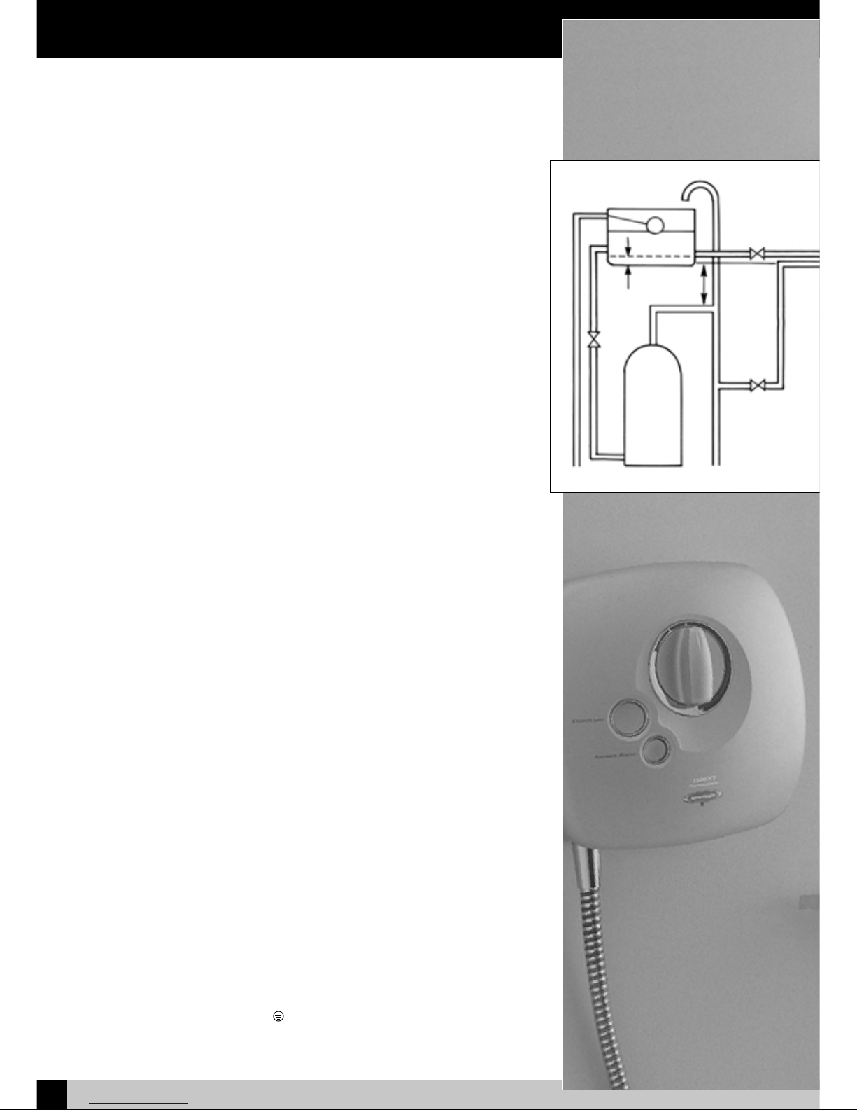
Fig. 1 – Gravity Power Shower Installation
1m
Minimum
60mm
Fitting your Shower
4
NEWTEAM 1500-XT
In addition to the recommendation on `Planning your Installation’ please take note of
the following:
• All plumbing should be completed before any electrical connections are undertaken.
• The unit can be connected to a combination cylinder system providing it
has a cold water storage capacity of 115 litres (25 gallons actual).
• When connecting pipework avoid using elbows: sweep or formed bends will
ensure optimum performance.
• Do not solder within 300mm of the unit.
• Do not run pump dry this will damage the internal seal and invalidate the warranty.
• All pipework to and from the unit should be a minimum of 15mm. Non-restrictive
isolating valves must be fitted on hot and cold supply pipes.
• Do not position unit in areas subjected to freezing conditions.
• The temperature of your stored water must not
exceed 65ºC. A stored water
temperature of 60ºC is considered sufficient to meet all normal requirements
in line with the British Standard 6700.
WARNING – ALL CONNECTING PIPEWORK SHOULD BE EARTHED
Procedure - Plumbing Connections: Fig 1.
1. Isolate mains water and electrical supplies.
2. To empty the pipework open the hot and cold water taps.
3. Make your connection into the hot water supply pipe from the cylinder, ensuring
that it is the first draw-off (below the expansion pipe tee) to minimise the effects
of water draw offs elsewhere in the house, and a minimum of 1 metre from the
base of the cold storage tank and the expansion tee.
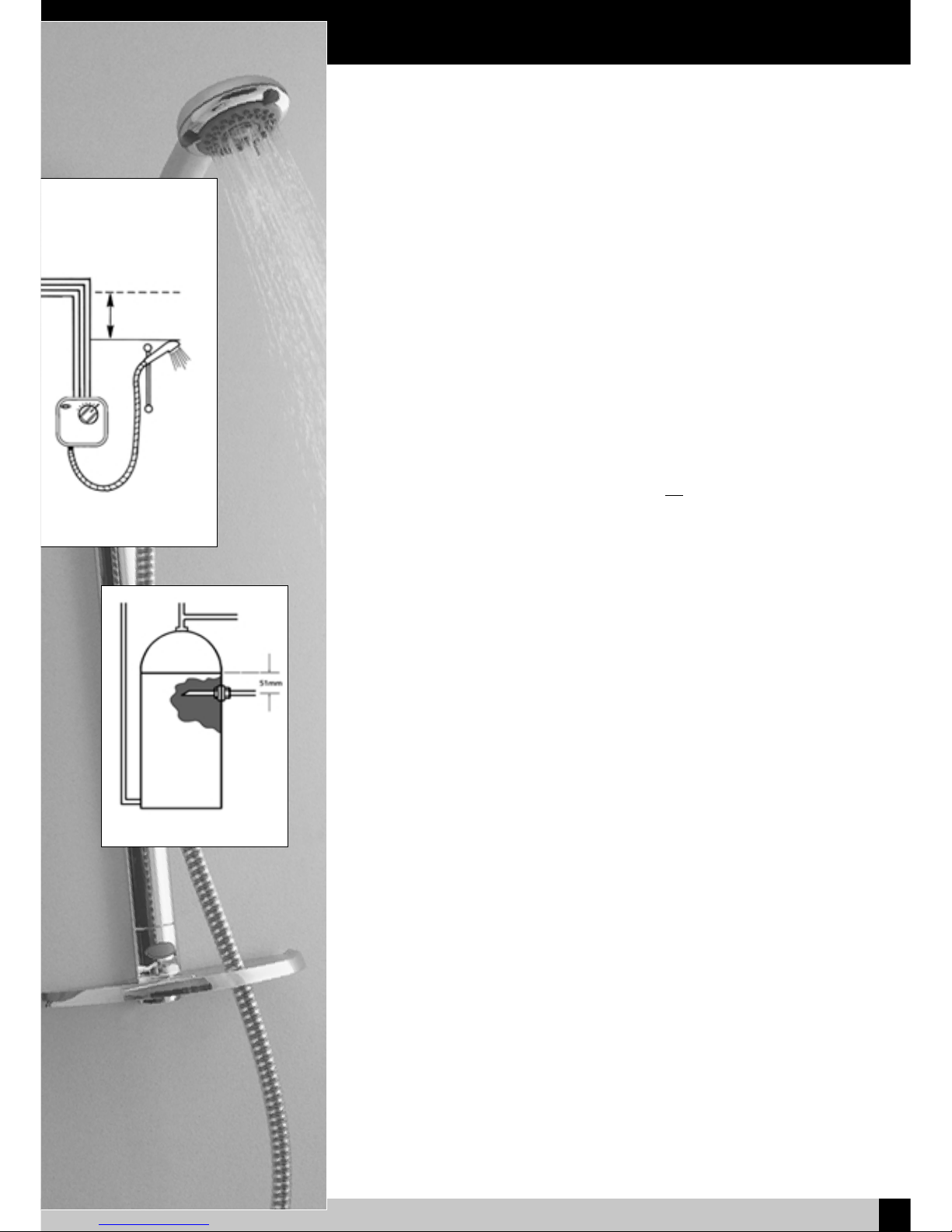
4. If this is not possible, a direct connection must be made from the hot water
cylinder with a cylinder flange, Fig 2.
5. The cold water supply should be taken directly from the cold storage tank,
and must be positioned 60mm below the cold feed connection to the hot
water cylinder. This should not be directly beneath the ball valve as aeration of the
water going to the shower could cause pump damage.
6. Run hot and cold pipework to the unit position.
We recommend that the unit is fitted at chest height, and set to one side of the
intended riser rail position, ensuring that the top of the unit is at least 75mm below
the base of the cold water tank.
IMPORTANT:
• The unit must be fitted on the finished tiled surface.
•
Do not seal the edge of the unit to the tiled surface with any sealant, as the
gap below the back of the unit and the tiles is needed for ventilation.
• The outlet connection must be positioned at the bottom of the unit.
General
The Unit
Fig 2 - Cylinder Flange
1m
Minimum
 Loading...