

Installation Instructions
and User Guide
PLEASE KEEP THIS BOOKLET
FOR FUTURE REFERENCE
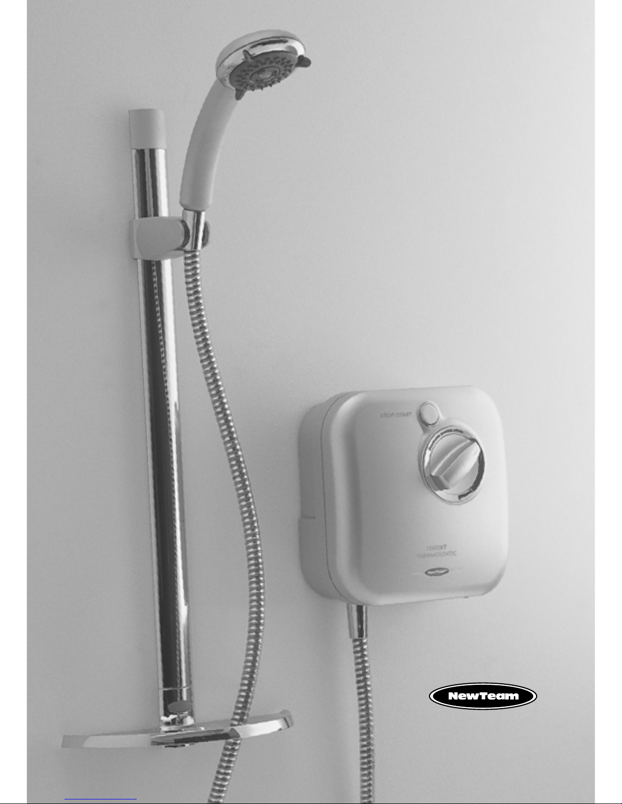
NEWTEAM 1000-XT
THERMOSTATIC POWER SHOWER
DEAR INSTALLER WHEN YOU HAVE READ THESE INSTRUCTIONS
PLEASE ENSURE YOU LEAVE THEM WITH THE USER
IN THE EVENT OF ANY QUERY PLEASE CONTACT
THE NEWTEAM CUSTOMER HELPLINE
Tel : 01536 264 012
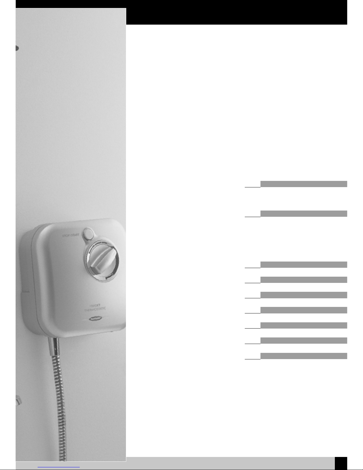
Product Features
1
NEWTEAM 1000-XT
NewTeam 1000-XT
• Integral pump
• Push-fit fittings
• 3 spray massage handset with
rub-clean feature
• Thermostatic temperature control
• Push button stop/start
• BEAB approval of safety
Contents
2
NEWTEAM 1000-XT
Please read this booklet carefully and ensure a competent person undertakes
the installation.
Note: Following the headings in sequence will guide you through the installation
and operation of your NewTeam 1000-XT Power Shower.
Refer to back cover for Guarantee, Customer Service and Replacement Parts Policy.
In the event of any query regarding installation please contact the NewTeam
Customer Service Department
Tel: 01536 264 012 • Fax: 01536 409 201
E-mail: service@newteam.co.uk • E-mail: spares@newteam.co.uk
In line with our policy of continual product development the specifications may be
varied and product design altered. We reserve the right to depart from the details
given in this manual without prior notice.
Pages
Installation and Operating Instructions
for NewTeam Power Shower
• 1000-XT
PLANNING YOUR INSTALLATION 3
• Plumbing
• Electrics
FITTING YOUR SHOWER 4-6
• General
• Plumbing Connections
• The Unit
• Water/Electrical Connections
• Riser Rail
COMMISSIONING 7
TEMPERATURE ADJUSTMENT 7
USER INSTRUCTIONS 8
TROUBLE SHOOTING 8
SPARE PARTS LISTING 9
INSTALLER NOTES 10
GUARANTEE 13
Planning your Installation
3
NEWTEAM 1000-XT
Plumbing
Under no circumstances should the unit be connected directly to the mains
cold water supply, or to a combination boiler, or pressurised hot water system.
For correct operation of the NewTeam 1000-XT power shower, both hot
and cold water supplies must be gravity fed, at nominally equal pressures,
from a cold water storage tank, and a hot water storage cylinder.
We recommend a minimum of 115 litres (25 gallon actual) of cold water
supplied by a storage tank. Please ensure compliance with all Water
Regulations. Under no circumstances must the Power Shower be
connected to the mains cold water supply.
Please ensure maximum supply head of 10 metres, minimum 75mm.
It is recommended that the hot water supply is at a temperature of 60ºC,
in line with British Standard 6700, British Water Regulations, and Plumbing
Code of Practice.
Do not use jointing compounds when connecting, and do not solder
within 300mm of the unit.
Before proceeding with the installation of this unit, check that your site
requirements allow the top of the unit to be a minimum of 75mm below the
bottom of the cold water storage tank.
Electrics
WARNING: THIS APPLIANCE MUST BE EARTHED.
All electrical wiring for the shower must comply with the current
I.E.E Regulations which includes earth-cross bonding to all metal pipework.
IMPORTANT:
All plumbing should be completed before final electrical connections are made.
The shower must be connected to a 230/240 volt A.C electrical supply from a
13-amp ring main, via a fused double pole switch with at least 3mm contact
separation. The switch is to be clearly identifiable, a minimum distance of 2.5m
from a fixed tap or shower, i.e. mounted in an adjacent room or via a ceiling-type
pull cord switch. The unit should be fused at no more than 3 amps.
This appliance must be earthed, and all associated metal pipework earth
crossbonded in line with current I.E.E regulations.
As the colours of the wires in the cable (not supplied) used to connect to this
appliance may not correspond with the coloured markings identifying the
terminals in your switch, please follow the procedure below:
Please use the cable entry point provided. Failure to comply will eliminate any
BEAB approval.
Procedure:
• The wire, which is coloured Blue or Black, must be connected to the terminal
that is marked with the letter N.
• The wire, which is coloured Brown or Red, must be connected to the terminal
that is marked with the letter L.
• The wire which is coloured Yellow/Green must be connected to the terminal
which is marked with the earth symbol .
• The installation and wiring must comply with I.E.E regulations.
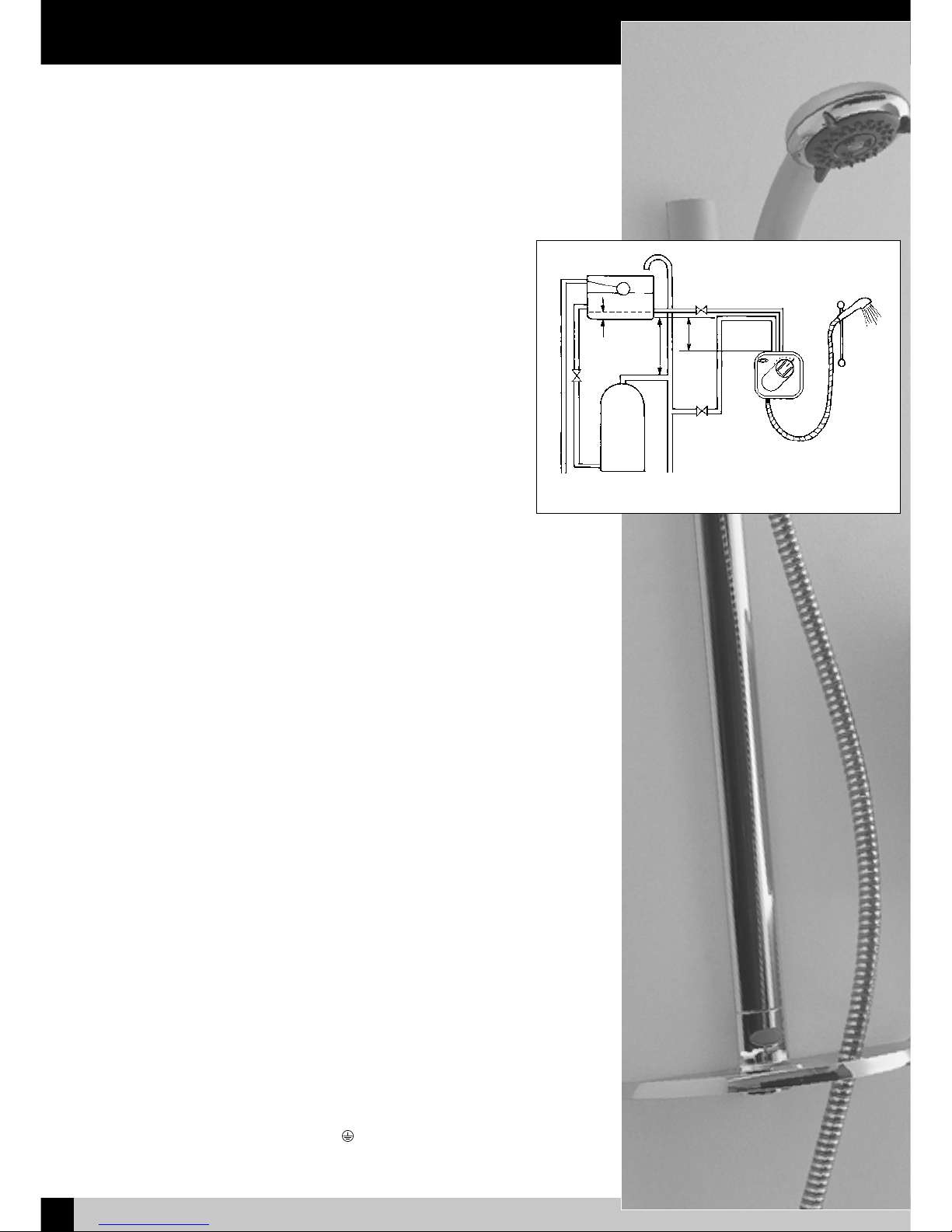
Fig 1 – Typical Power Shower Installation
60mm
1m
min
75mm
min
Fitting your Shower
4
NEWTEAM 1000-XT
General
In addition to the recommendation on `Planning your Installation’ please take note
of the following:
• All plumbing should be completed before any electrical connections are
undertaken.
• The unit can be connected to a combination cylinder system providing it
has a cold water storage capacity of 115 litres (25 gallons actual).
• When connecting pipework avoid using elbows: sweep or formed bends will
ensure optimum performance.
• Do not solder within 300mm of the unit.
• Do not run pump dry this will damage the internal seal and invalidate the
warranty.
• All pipework to and from the unit should be a minimum of 15mm. Non-restrictive
isolating valves must be fitted on hot and cold supply pipes.
• Do not position unit in areas subjected to freezing conditions.
• The temperature of your stored water must not
exceed 65ºC. A stored water
temperature of 60ºC is considered sufficient to meet all normal requirements
in line with the British Standard 6700.
WARNING – ALL CONNECTING PIPEWORK SHOULD BE EARTHED
Procedure - Plumbing Connections: Fig 1.
1. Isolate mains water and electrical supplies.
2. To empty the pipework open the hot and cold water taps.
3. Make your connection into the hot water supply pipe from the cylinder, ensuring
that it is the first draw-off (below the expansion pipe tee) to minimise the effects
of water draw offs elsewhere in the house, and a minimum of 1 metre from the
base of the cold storage tank and the expansion tee.
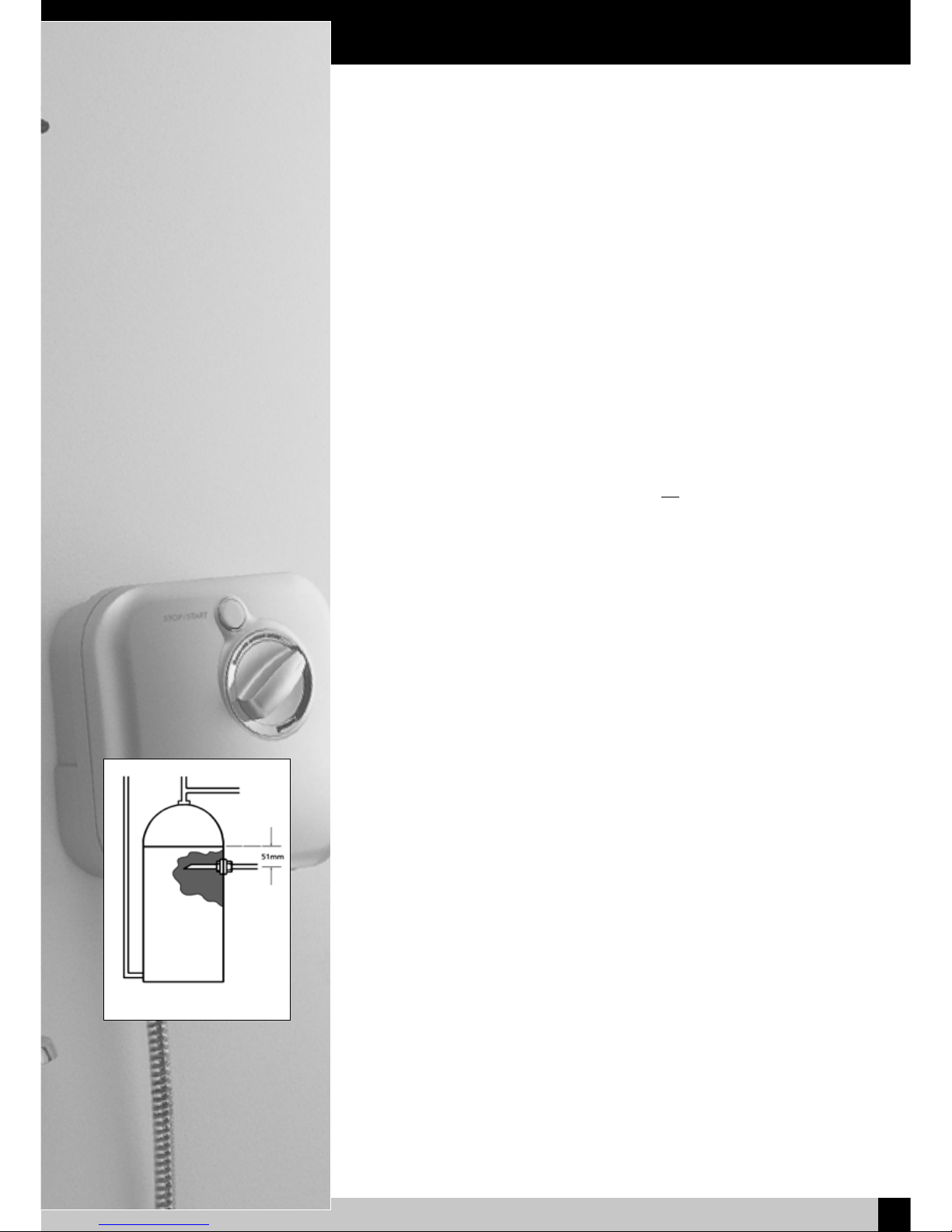
4. If this is not possible, a direct connection must be made from the hot water
cylinder with a cylinder flange, Fig 2.
5. The cold water supply should be taken directly from the cold storage tank,
and must be positioned 60mm below the cold feed connection to the hot
water cylinder. This should not be directly beneath the ball valve as aeration of
the water going to the shower could cause pump damage.
6. Run hot and cold pipework to the unit position.
The Unit
We recommend that the unit is fitted at chest height, and set to one side of the
intended riser rail position, ensuring that the top of the unit is at least 75mm below
the base of the cold water tank.
IMPORTANT:
• The unit must be fitted on the finished tiled surface.
• Do not seal the edge of the unit to the tiled surface with any sealant, as the
gap below the back of the unit and the tiles is needed for ventilation.
• The outlet connection must be positioned at the bottom of the unit.
Fig 2 – Cylinder Flange

Fitting your Shower
5
NEWTEAM 1000-XT
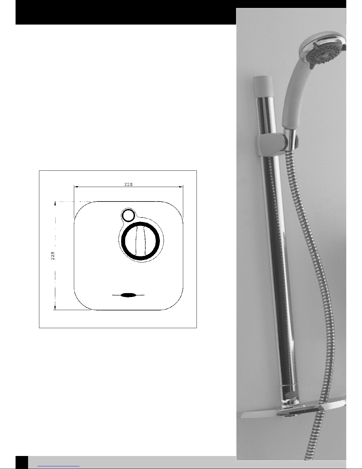
Measurements
given in the table
are to be taken
from these points
Inlet
elbows
Short
Inlet Elbow
Top/Bottom 63mm
Feed
Long
Inlet Elbow
Top/Bottom 86mm
Feed
Both
Inlet Elbow
Back Feed 63mm
Collet
Fig 4 - Push fit fittings.
Water/Electrical Connections
WARNING:
Do not fit fuse or switch on mains electrical supply until all plumbing work is
completed. Connecting pipework can feed from above or below the unit, or straight
through the wall at nominal centres of 40mm.
Top Feed = Hot on the right /cold on the left
Bottom Feed = Hot on the left/cold on the right
Back Feed = Hot on the bottom/cold on the top
Procedure:
• The integral fittings on the valve are of the self-seal push-fit type. All burrs and
rough edges must be removed from the end of the tube. Where chrome plated
tube is used, roughen or remove the first 25mm of plating
• The inlet elbows supplied are of a standard length, in some cases these will
need to be shortened for correct installation, please refer to the tables for
correct measurements.
1000-XT
1. Flush out pipework before installing the unit.
2. Cut the inlet elbows to the required length, please refer to table below.
3. Locate the inlet elbows into the mixer valve inlets by pushing firmly through
rubber grommets until pipe stop is felt.
4. Hold the unit on the wall and mark the pipe work to the appropriate length.
5. Cut the pipes and remove all burrs. Push the unit and elbows firmly onto the pipes
until the stop is felt.
6. Mark the fixing points for the unit, Fig 3.
7. Release unit from pipes by pressing the collets on the elbow fittings, and pulling
the unit off the pipework, Fig 4.
8. Drill the wall and insert the appropriate wall fixings.
9. Bring a supply cable (to conform to I.E.E regulations) from the switch to the unit
position. The cable can enter the unit from the rear, or via channels in the base
of the unit, and the bottom or the right hand side.
10.
Feed the supply cable in to the unit but do not connect.
11.
Refit unit to pipes and secure to wall using 32mm x No.8 screws provided.
12.
Connect the supply cables into the appropriate terminals (marked N, L and
symbol) on the terminal block, and secure into position with the cable clamp.
13.
Do not fit the front cover at this stage. Refer to the commissioning procedure
on page 7.
Note: If the electrical supply cable is concealed in the wall ensure that it avoids
the unit’s fixing points so that fixing screws do not pierce the cable.
Fig 5 - Fixing screws.
Fig 3 - Fixing points.
Cold
Hot

Fixing the Riser Rail
6
NEWTEAM 1000-XT
Spirit Rail Kit
Before proceeding with fitting the rail, identify each of the items supplied using the
illustration.
The slider need not be removed from the rail during fitting. The top of the slider has
a smooth profile, whereas the underside has a recess revealing the grooves on the
handset holder.
Fit the soap dish onto the bottom end of the rail and secure using the small screw
from the kit.
Position the rail on the wall, bearing in mind the heights of people likely to use the
shower, and the length of the hose when connected to the shower and passed
through the retaining hole in the soap dish. Mark the wall to indicate the upper
fixing screw position. Screw centres are 605 mm (approx. 23 - inches,) apart.
Drill the wall at the marked fixing position using a 6 mm drill, and loosely fix the rail
end, checking that the rail is hanging vertically using the spirit level incorporated
into the top end of the rail. The bubble should be exactly between the two lines on
the spirit level body. Mark the position for the lower fixing screw, move the rail to
one side, drill the wall, and fix the lower end of the rail.
Check that the rail is vertical and tighten both fixing screws.
Slide the end cap into position on the top end of the rail, and fit the screw cover
into the recess in the soap dish.
When fitting the hose, it should pass through the larger hole of the soap dish.
Note: The hose nut, and not the handset handle, fits into the slider, and the slider
moves more freely on the rail if gripped next to the rail, rather than at the handset.
Fitting the Riser Rail
Fig 6 - Riser Rail
No Part Description
1 Rail end cap
2 Spirit level
3-4 Rail with slider attached
5 Soap Dish
6 Screw cap
7 Soap dish fixing screw
Rail fixing screws &
wall plugs

Commissioning
7
NEWTEAM 1000-XT
Commissioning
1. With the front cover removed ensure the black ‘purge/shower’ switch inside the
base is switched to purge (see A, fig 7). This enables water to flow without the
pump running which is necessary in the following commissioning process.
2. Fit the front cover and fix with fixing screws (see fig 5).
3. Push the temperature control knob onto the spindle with the marker pointing to
the ‘12 o’clock’ position.
4. Connect the shower hose to the unit but do not fit the handshower.
5. Turn on the hot and cold water isolating valves, and the electricity-isolating switch.
Place the open end of the hose in the bath or shower tray.
6. Set the temperature control knob to fully cold (marker at ‘6 o’clock’ position) and
press the ‘stop/start’ button. The pump will not operate but water should run.
7. Cold water will flow from the hose, and you should allow this to continue for two
minutes after which the control knob should be returned to the ‘12 o’clock’
position . Allow the water to run for a few minutes to stabilise the hot water flow.
8. Turn off the electricity at the isolating switch and remove the knob and cover.
Switch the black ‘purge/shower’ switch to shower and refit the cover and knob
ensuring the marker on the knob points to the ‘12 o’clock’ position.
9. Turn on the electricity at the isolating switch.
10.
Pass the hose through the hole in the front of the soap dish and fit the handshower
11.
Your shower is now ready to run. Press the stop/start button on the front cover to
operate the shower, which will work as a power shower.
12.
It is intended that with the temperature knob aligned to the ‘12 o’clock’ position
you should get a comfortable shower temperature. If however the shower is too
hot or too cold remove the control knob and adjust the brass spindle anti-
clockwise to increase temperature – clockwise to decrease. When the desired
shower temperature is achieved replace the knob with the marker pointing to the
‘12 o’clock’ position.
Temperature Adjustment
The valve allows the maximum showering temperature to be set at a safe level,
preventing accidental scalding. This setting should be made during commissioning
and will require that the hot water cylinder is at its normal operating temperature.
IMPORTANT:
• The handset must be in the spray mode.
• We recommend the reading of User Instructions before proceeding further.
This will familiarise you with the operation of the shower.
Procedure:
Turn the brass mixer valve spindle fully clockwise, and then anti-clockwise until the
black line on the spindle is aligned with the groove on the mixer body, and fit the
control knob in the fully cold position. Check that it is correctly fitted by turning fully
clockwise to the stop, pull the knob off and check that the black line and groove are
aligned. Adjust if necessary. This sets the shower temperature to 38-40ºC, with
the control knob pointing to ‘12 o’clock’, if the stored hot water is at the
recommended 60ºC.
Fig 7
- Commissioning process.
A

User Instructions
8
NEWTEAM 1000-XT
NewTeam 1000-XT
1. To operate the shower ensure the temperature control knob is set approximately
to the ‘12 o’clock’ position and press the stop/start button.
2. For a hotter shower turn the control knob anti-clockwise, for a cooler shower
turn it clockwise.
3. The handset holder has a friction grip on the rail and simply slides up and down
to adjust the height. The angle of the handset can also be adjusted.
4. The handshower has three shower modes, which are selected by rotating the
bezel around the spray head.
Trouble shooting
Symptom
Pump not operating but
water is flowing
Pump not operating
and no water is flowing
Pump operates but no
water is flowing
Poor performance
Likely Cause
Purge/shower switch
switched to purge
No electricity supply
to unit
No water supply to unit
Restrictions in water
supply
Pump may have
overheated
Unit may be incorrectly
installed
Action/Remedy
Isolate electrical supply,
remove cover and
switch to shower
Check all fuses and
electrical supply
Check isolating
valves are turned on
Check cold-water
storage tank has not
run dry
Check both hot and
cold isolating valves
are fully open
Allow unit to cool
and retry
Check that the top
of the shower unit
is at least 75 mm
below the base of
the cold-water tank
If in doubt please call the NewTeam helpline: 01536 264012

Spare Parts Listing
9
NEWTEAM 1000-XT
Fig 8 - Spare parts.
NewTeam 1000-XT
Item No. Part No. Description Finish
1 SP-087-0603 Base assembly*# White or matt chrome
2 SP-087-0604 Front cover*# White or matt chrome
3 SP-087-0110 Pump unit Not applicable
4 SP-087-0035 Motor cover Not applicable
5 SP-087-0127 Pipe connection Not applicable
6 SP-087-0230 Solenoid Not applicable
7 SP-087-0014 Front cover screws* Not applicable
8 SP-087-0129 Latching switch* Not applicable
9 SP-086-0061 Long inlet elbow x 2* Not applicable
10 SP-087-0154 Mixer valve assembly Not applicable
11 SP-087-0505 Temperature control knob*# White or matt chrome
12 SP-087-0514 Stop/start button*# White or matt chrome
13 SP-087-0068 Pipe cover*# White or matt chrome
14 SP-087-0211 Purge/shower Not applicable
rocker switch*
15 SP-280-0100 Spirit rail and White or
slider assembly*# matt chrome/chrome
16 SP-280-0033 Soap dish*# White or chrome
17 SP-280-0024 Rail end cap*# White or matt chrome
18 SP-285-0820 Hose*# White or chrome
19 SP-168-0204 Zag Handshower*# White or matt chrome
* Not shown # Please define colour
6
10
3
4
5

Installer Notes
10
NEWTEAM 1000-XT

Installer Notes
11
NEWTEAM 1000-XT

Installer Notes
12
NEWTEAM 1000-XT

Guarantee/Service Policy
13
NEWTEAM 1000-XT
Guarantee
Thank you for purchasing a NewTeam product, which has been designed, manufactured and
tested, in the U.K., to the highest standards.
Guarantee. 2 Years, 1 Year - Parts and Labour Second Year- Parts Only
This is provided that:
1. The guarantee registration card is completed and returned within ten days complete with a copy
of proof of purchase.
2. The product is installed and operated in accordance with our instructions and has not been
misused or damaged.
This in no way affects your statutory rights as a consumer.
The information on the Guarantee card helps NewTeam to process any claims and contact you
about your product and its maintenance if required. The registration of your personal details is
purely for Newteam use, and the other information helps us to make products for the future.
NewTeam Shower products are designed, manufactured and tested to the highest standards.
Should a complaint arise, products are guaranteed against faulty workmanship and materials for a
period of 12 months from the date of purchase, when in domestic use (second year guarantee is
parts only). For your guarantee to be valid, your shower pump must be installed by a competent
person, in accordance with the instruction manual.
NewTeam will repair or replace (at our option), free of charge, any faulty components during the
guarantee period, provided it has been maintained and operated in accordance with our
instructions, and has not been misused or damaged.
Modification or repair of this product by person(s) not authorised by NewTeam will invalidate this
guarantee.
This guarantee applies to products purchased within the United Kingdom or Republic of
Ireland, but does not apply to products used commercially.
This guarantee does not affect your statutory rights.
Service Policy – Replacement Parts Policy
IMPORTANT:
In the event of product or component malfunction, DO NOT tamper with or remove the product
from site. Telephone NewTeam Customer Service Department on 01536 264 012 and be
prepared with the date of purchase, model number and a description of the complaint.
Our service staff are fully qualified to advise on correct installation procedures and will be able to
diagnose whether the fault will require a replacement part or a visit from a NewTeam
engineer.
If required, a service call will be booked, and either yourself or an appointed representative (who
should be a person of 18 years or over) must be present during the visit.
All site visits to product within the guarantee period will be carried out free of any parts or
labour charges provided the conditions of the guarantee have been adhered to. (Second year
guarantee is parts only)
All site visits to product out of guarantee will be subject to charges for parts and labour which is
payable by you or your appointed representative at the time of the visit. Charges will also be levied
on cancelled appointments, unless advised to NewTeam at least 24 hours in advance of the agreed
date and time.
We reserve the right not to undertake work where payment cannot be made to our engineer at the
time of the visit.
NewTeam hold stocks of components for all their range of products and these will be
maintained for the duration of their life.
Should a product be discontinued, spare parts stocks will be maintained, but in the event of a part
becoming unavailable NewTeam reserve the right to supply a substitute of equal quality.
The following payment methods can be used to obtain spare parts:
By post, pre-payment of proforma invoice by cheque or postal order.
By telephone quoting credit card (Mastercard, Visa or Visa Delta) details.
Part No. 404-0125 Issue 02/03
REPLACEMENT PARTS:
Tel: 01536 409 222 • Fax: 01536 409 201 • E-Mail:spares@newteam.co.uk
CUSTOMER SERVICE HOTLINE:
Tel: 01536 264 012 • Fax: 01536 409 201 • E-Mail:service@newteam.co.uk

Guarantee
14
NEWTEAM 1000-XT
Please post immediately enclosing a copy of proof of purchase
GUARANTEECARD
NAME:
ADDRESS:
POSTCODE:
DATE OF PURCHASE:
PRODUCT PURCHASED FROM:
TOWN:
NewTeam’s philosophy is to offer outstanding products with quality and integrity,
please help us by taking the time to answer the following questions. Thank you.
POST BACK
FOLD AND TAPE AS INSTRUCTED OVERLEAF
MARKETING INFORMATION
1. Please state your profession: Plumber ❒ Builder ❒ Electrician ❒ Customer ❒
Other ❒ (please specify) ______________________________________________________________
2. Please state the reason for purchasing a shower: New Build
❒ Replacement ❒
Renovation ❒ Other ❒ (please specify) ________________________________________________
3. If the product is a replacement shower, please state the type and make of the shower it is
replacing:____________________________________________________________________________
4. What influenced you to purchase the 1000-XT Power Shower? Advertisement
❒
Trade Press ❒ Recommendation from Stockist ❒ Recommendation from Installer ❒
Other ❒ (please specify) ______________________________________________________________
5. Please state your main reason for purchasing the 1000-XT Power Shower:
NewTeam Product Knowledge
❒ Product Features ❒ Product Styling ❒ Price ❒
Other ❒ (please specify) ______________________________________________________________
Please tick here if you do not require any further information or product updates from NewTeam ❒
FOR NEWTEAM USE
This label identifies your product and
provides all the information needed
AFFIX PRODUCT LABEL HERE
✁
NewTeam Power Shower
1000-XT
Proof of purchase enclosed
YES ❐ NO ❐

NewTeam Ltd.
Customer Service Dept.
Brunel Road
Earlstrees Industrial Estate
Corby
Northants
NN17 4JW
1st Fold
2nd Fold
3rd Fold
✁
Please tape down
Please tape down
Affix
Stamp
 Loading...