

Page 1

IP-PBX Series
OM10
OM20
OM200
User Manual
New Rock Technologies, Inc.
Building 11, 777 Long Wu Road
Shanghai, 200232
China
www.newrocktech.com
Tel: 0086-21-61202700
E-mail: [email protected]
Page 2

Shanghai New Rock Technologies Inc. Page2/75
Amendent Records
Document Rev. 2.0 (Jan. 07, 2010)
Content updates of the document are as follows:
1) Several features are added, including dumping the TDM signal and IP packets from
Web-based utility
2) Changes are made for the configuration of analog extension, IP extension, IP trunks,
and attendant, and dialing plan and feature codes
Document Rev. 1.1 (Oct. 27, 2009)
Content updates of the document are as follows:
3) Adjustment of content was made based on the new Web user interface.
4) OM20 and OM200 were added.
5) Instructions for use of r ec ording, tie trun k and othe r new f unct ions w ere adde d.
Copyright © 2010 New Rock Technologies, Inc. All rights reserved
All or part of this document may not be excerpted, reproduced and transmitted in
any form or by any means without prior written permission from the company.
Page 3

Shanghai New Rock Technologies Inc. Page3/75
Contents of Table
1 Overview ........................................................................................................................................9
1.1 Introduction...........................................................................................................................................9
1.2 Functions and Features..........................................................................................................................9
1.3 Equipment Structure............................................................................................................................10
1.3.1 OM10......................................................................................................................................10
1.3.2 OM20......................................................................................................................................12
1.3.3 OM100....................................................................................................................................14
1.3.4 OM200....................................................................................................................................16
2 Parameter Setting........................................................................................................................21
2.1 Login to Web-based Utility.................................................................................................................21
2.1.1 Obtain OM IP Address............................................................................................................21
2.1.2 Logon......................................................................................................................................22
2.2 Buttons Used on OM Web-based Utility.............................................................................................23
2.3 Basic Configuration.............................................................................................................................23
2.3.1 Status.......................................................................................................................................23
2.3.2 Network Configuration ...........................................................................................................23
2.3.3 Dialing Rules...........................................................................................................................26
2.3.4 Auto Attendant........................................................................................................................28
2.4 Extension.............................................................................................................................................29
2.4.1 Analog Ext..............................................................................................................................29
2.4.2 IP Ext. .....................................................................................................................................33
2.4.3 Department..............................................................................................................................34
2.4.4 Department..............................................................................................................................36
2.5 Trunking..............................................................................................................................................37
2.5.1 Analog Trunk..........................................................................................................................37
2.5.2 IP Trunk..................................................................................................................................38
2.5.3 IP Trunk Registration..............................................................................................................39
2.6 System.................................................................................................................................................40
2.6.1 Characteristics of trunk line....................................................................................................40
2.6.2 Characteristics of line..............................................................................................................41
2.6.3 Greeting...................................................................................................................................43
2.6.4 Recording................................................................................................................................44
2.6.5 Call Record .............................................................................................................................45
2.6.6 Functional keys.......................................................................................................................46
2.6.7 Tones.......................................................................................................................................48
2.7 Advanced Configuration.....................................................................................................................49
2.7.1 System.....................................................................................................................................49
Page 4

Shanghai New Rock Technologies Inc. Page4/75
2.7.2 Media......................................................................................................................................51
2.7.3 SIP related configuration.........................................................................................................54
2.7.4 Routing Table.......................................................................................................................... 55
2.7.5 Application Examples of Routing Table.................................................................................59
2.7.6 Digit Map................................................................................................................................60
2.7.7 Tie trunk..................................................................................................................................61
2.7.8 Encrypt....................................................................................................................................64
2.8 Log management ................................................................................................................ .................65
2.8.1 Resource status........................................................................................................................65
2.8.2 Call message ...........................................................................................................................67
2.8.3 System Startup........................................................................................................................67
2.8.4 Configure log ..........................................................................................................................67
2.9 System tool..........................................................................................................................................68
2.9.1 Change password ....................................................................................................................68
2.9.2 Software upgrade ....................................................................................................................69
2.9.3 Configuration import...............................................................................................................70
2.9.4 Configuration export...............................................................................................................71
2.9.5 Software restart.......................................................................................................................71
2.9.6 System reboot..........................................................................................................................71
2.9.7 Restore factory settings...........................................................................................................72
2.9.8 TDM Capture..........................................................................................................................72
2.9.9 Ethereal capture.......................................................................................................................72
2.10 Product information...........................................................................................................................72
2.11 Logout...............................................................................................................................................73
3 Appendix......................................................................................................................................74
3.1 OM200 system operation state............................................................................................................74
3.2 Setting of Recording Storage Server...................................................................................................74
Page 5

Shanghai New Rock Technologies Inc. Page5/75
Contents of Figure
Figure 1-1 OM10 Front Panel...................................................................................................................11
Figure 1-2 OM10 Back Panel.................................................................................................................... 11
Figure 1-3 OM20 Front Panel...................................................................................................................12
Figure 1-4 OM20 back panel.....................................................................................................................14
Figure 1-5 OM100 Front Panel.................................................................................................................15
Figure 1-6 OM100 Back Panel..................................................................................................................15
Figure 1-7 OM200 Front Panel.................................................................................................................17
Figure 1-8 OM200 Back Panel..................................................................................................................18
Figure 1-9 Schematic Diagram for Front Panel of OM200 Dual-Chassis System.....................................19
Figure 1-10 Schematic Diagram for Back Panel of OM200 Dual-Chassis System...................................20
Figure 2-1 Login Interface of OM Web-based Utility...............................................................................22
Figure 2-2 Status Interface........................................................................................................................23
Figure 2-3 Network Configuration Interface.............................................................................................24
Figure 2-4 Dialing rule configuration interface.........................................................................................27
Figure 2-5 Configuration interface of Auto Attendant..............................................................................28
Figure 2-6 Basic configuration interface of analog extension...................................................................29
Figure 2-7 Others configuration interface of analog extension .................................................................31
Figure 2-8 Basic configuration interface of IP extension..........................................................................33
Figure 2-9 Others configuration interface of IP extension........................................................................34
Figure 2-10 Registration configuration interface of IP extension..............................................................35
Figure 2-11 Department configuration interface.......................................................................................37
Figure 2-12 Configuration interface of analog trunk.................................................................................37
Figure 2-13 General configuration interface of IP trunk...........................................................................38
Figure 2-14 Registration configuration interface of IP trunk.....................................................................39
Figure 2-15 Trunk line characteristics configuraiton interface..................................................................40
Figure 2-16 Line characteristics configuration interface...........................................................................41
Figure 2-17 Configuration interface of greeting........................................................................................43
Figure 2-18 Configuration interface of recording......................................................................................44
Figure 2-19 Framework of Recording.......................................................................................................45
Figure 2-20 Configuration interface of call record....................................................................................45
Figure 2-21 Functional keys configuration interface.................................................................................46
Figure 2-22 Configuration interface of tones............................................................................................49
Figure 2-23 Inferface of system advanced configuraiton..........................................................................50
Figure 2-24 Configuration interface of media...........................................................................................52
Figure 2-25 SIP related configuration interface........................................................................................54
Figure 2-26 Configuration Interface for Routing Table.............................................................................55
Figure 2-27 Illustrative interface for routing configuration....................................................................... 56
Figure 2-28 Configuration Interface for Digit Map...................................................................................60
Figure 2-29 Configuration interface of tie trunk.......................................................................................62
Page 6

Shanghai New Rock Technologies Inc. Page6/75
Figure 2-30 Reference Tie Trunk Diagram...............................................................................................62
Figure 2-31 Tie Trunk Application Diagram in OM.................................................................................64
Figure 2-32 Encrypt configuration interface.............................................................................................64
Figure 2-33 System Status Interface..........................................................................................................66
Figure 2-34 Call message interface...........................................................................................................67
Figure 2-35 Interface of system startup.....................................................................................................67
Figure 2-36 Interface of debugging log management................................................................................68
Figure 2-37 Interface of password changing.............................................................................................69
Figure 2-38 Interface of software upgrade................................................................................................69
Figure 2-39 Interface of file upload...........................................................................................................69
Figure 2-40 Upgrade interface...................................................................................................................70
Figure 2-41 Prompt of upgrade process ....................................................................................................70
Figure 2-42 Interface of successful upgrade.............................................................................................. 70
Figure 2-43 Interface of import data..........................................................................................................71
Figure 2-44 Interface of export data..........................................................................................................71
Figure 2-45 Configuration interface of product information.....................................................................72
Page 7

Shanghai New Rock Technologies Inc. Page7/75
Contents of Table
Table 1-1 Differences Between OM Series.................................................................................................9
Table 1-2 OM10 Configurations...............................................................................................................10
Table 1-3 Description of OM10 Front Panel.............................................................................................11
Table 1-4 Description of OM10 back panel..............................................................................................11
Table 1-5 Configuration Description of Analog Extension Interfaces for OM10......................................11
Table 1-6 OM20 Configuration.................................................................................................................12
Table 1-7 Description of OM20 Front Panel.............................................................................................12
Table 1-8 Pins and Indicators for FXS and FXO of OM20.......................................................................13
Table 1-9 for Pin and Indicator Table of Ethernet Ports............................................................................13
Table 1-10 Indicators of OM20.................................................................................................................13
Table 1-11 Description of OM20 Back Panel...................................................................................... .....14
Table 1-12 Properties of OM20 CON Port................................................................................................14
Table 1-13 OM100 Configuration.............................................................................................................14
Table 1-14 Description of OM100 Front Panel .........................................................................................15
Table 1-15 Indicators of OM100...............................................................................................................15
Table 1-16 Description of OM100 Back Panel .........................................................................................16
Table 1-17 OM200 Configuration.............................................................................................................16
Table 1-18 Description of OM200 Front Panel .........................................................................................17
Table 1-19 Pin Specifications for OM200 RJ45 Socket Port....................................................................17
Table 1-20 Corresponding Relation Between OM200 RJ45 Socket and Line Number.............................17
Table 1-21 OM200 Back Panel.................................................................................................................18
Table 1-22 Meanings of OM200 Indicators..............................................................................................19
Table 2-1 Default IP Address of OM........................................................................................................21
Table 2-2 Default Passwords of OM .........................................................................................................22
Table 2-3 Configuration parameter of Network........................................................................................24
Table 2-4 Configuration parameters of dialing plan..................................................................................27
Table 2-5 Configuration Parameters of Auto Attendant............................................................................28
Table 2-6 Basic configuration parameter of analog extension...................................................................29
Table 2-7 Others configuration parameter of analog extension.................................................................31
Table 2-8 Basic configuration parameter of IP extension..........................................................................33
Table 2-9 Others parameter of IP extension..............................................................................................34
Table 2-10 Registration configuration parameter of IP extension.............................................................35
Table 2-11 Configuration parameter of analog trunk ................................................................................37
Table 2-12 General configuration parameter of IP trunk...........................................................................38
Table 2-13 Registration configuration parameter of IP trunk....................................................................39
Table 2-14 Configuration parameter of trunk line characteristics.............................................................40
Table 2-15 Line characteristics configuration parameter ..........................................................................41
Table 2-16 Voice File Table Used on the OM...........................................................................................43
Table 2-17 Configuration parameter of recording.....................................................................................44
Page 8

Shanghai New Rock Technologies Inc. Page8/75
Table 2-18 Configuration parameter of call record...................................................................................46
Table 2-19 The use of feature codes..........................................................................................................46
Table 2-20 Configuration parameter of tones............................................................................................49
Table 2-21 Parameters of system advanced configuration ........................................................................50
Table 2-22 Configuration parameter of media..........................................................................................52
Table 2-23 Codec Methods Supported by OM..........................................................................................53
Table 2-24 Mapping between the reliability requirement and the TOS value...........................................53
Table 2-25 Configuration parameter of SIP related...................................................................................54
Table 2-26 Routing Table Format.............................................................................................................57
Table 2-27 Number Transformations........................................................................................................57
Table 2-28 Routing Destination................................................................................................................59
Table 2-29 Description of Digit map.........................................................................................................61
Table 2-30 Configuration parameter of tie trunk....................................................................................... 62
Table 2-31 Intelligent Routing Table........................................................................................................63
Table 2-32 Trunk Routing Table of OM Reference Configuration...........................................................63
Table 2-33 Encrypt configuration parameters...........................................................................................64
Table 2-34 Parameters of system status.....................................................................................................66
Table 2-35 Configuration parameters of debugging log management.......................................................68
Table 3-1 OM200 system operation state..................................................................................................74
Table 3-2 Hardware Requirements for Recording Storage Sever..............................................................74
Table 3-3 Specification of OM Recording................................................................................................74
Page 9

Shanghai New Rock Technologies Inc. Page9/75
1 Overview
1.1
Introduction
Officium (hereinafter called “OM”) is a “All-in-One” business telephone system designed for small
and mid-size enterprises. It is integrated with Internet telephony, legacy PBX features, instant
messaging, user status display, and local and remote management mechanism to provide an efficient
and easy-to-use unified communication platform for office staff. Featuring built-in interfaces to
analog phones, PSTN lines, SIP-based trunks and SIP registration service, OM connects directly to
analog phones, facsimile machines, lines from local Central Office, as well as to components in IP
telephony network such as soft switches, IP-PBXs and SIP telephone and soft phone. OM offers
functions such as auto-attendant, monitoring of extension status, mobile extension, callback,
corporate CRBT, click-to-dial, call transfer, call waiting, voice mail, call recording and etc.
OM is a cost-effect solution for carriers to deploy business telephone service to enterprises, and it is
also used for small and mid-size enterprises to build private telephone system serving multi-location
branch offices and home working.
OM Series include OM10,OM20,OM100 and OM200 subseries. Their features are similar with the
main differences as follows:
Table 1-1 Differences Between OM Series
Capacity Chassis Line Card
Install
ation
Power
OM10
Able to configure
4-8 user ports and
register 30 IP
extensions
Plastic casing Built-in
Deskt
op
5-9 VDC
OM20
Able to configure
16-24 user ports
and register 60 IP
extensions
19–inch wide
and 1U high
chassis
Built-in Rack 100-240 VAC
OM100
Able to configure
24-48 user ports
and register 120 IP
extensions
19–inch wide
and 1U high
chassis
Pluggable Rack
100-240 VAC,
-48 VDC
(Optional)
OM200
Able to configure
32-96 user ports
and register 120 IP
extensions
19–inch wide
and 1U high
main chassis and
extension
chassise as
option
Pluggable Rack
100-240 VAC,
-48 VDC
(Optional)
1.2
Functions and Features
z
Built-in SIP register and proxy server
z
Local analog extensions and remote SIP extensions
z
Mobile extensions
z
Auto-attendant
Page 10

Shanghai New Rock Technologies Inc. Page10/75
z
Operator
z
Direct inward dialing (DID)
z
Automatic call distribution
z
Extension features such as call forwarding, call waiting, call hold, call pickup, call transfer,
five-level call restriction, CRBT, and etc.
z
Voice mail and call recording
z
Mornitoring of extension and trunk status
z
Encryptions
z
Call logs
z
Call detailed record
z
Web-based utility for local and remote management
z
SIP-based Tie trunks
z
Routing table up to 100 rules
z
Gain adjustment of extensions and analog trunks
z
STUN and NAT traversal
z
Support terminals including telephone, facsimile machine and PBX
z
T.30/T.38 fax
z
Second stage dialing or voice prompt over FXO ports
z
PSTN failover through FXO ports
z
XML/HTTP-based API for 3rd party application software
1.3
Equipment Structure
1.3.1 OM10
OM10 is the product with smallest capacity in OM IPPBX Series. Designed with small plastic
structure for desktop placement, OM10 can provide up to 8 analog line interfaces. OM10 supports the
following types of configuration:
Table 1-2 OM10 Configurations
Models Local extension Analog trunks SIP extensions SIP trunks
OM10-4S 4 0 30 20
OM10-8S 8 0 30 20
OM10-4FXO 0 4 30 20
OM10-8FXO 0 8 30 20
OM10-4S/4 4 4 30 20
Page 11
Shanghai New Rock Technologies Inc. Page11/75
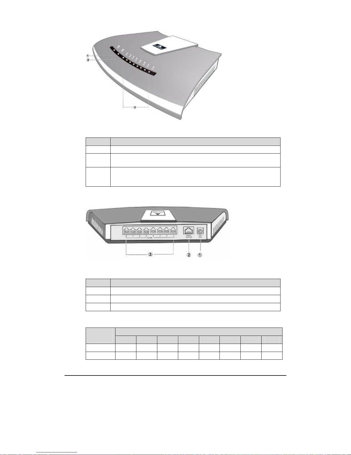
Figure 1-1 OM10 Front Panel
Table 1-3 Description of OM10 Front Panel
# Description
① Power indicator (PWR), the light on indicates that it has been powered.
②
Ethernet interface indicator (ETH), the light on indicates successful connection, the
light flashing indicates that data packets are being received or sent.
③
Analog line (FXS) or analog trunk (FXO) interface indicator, the light on indicates
that it is in use. After power-on and normal startup, FXS or FXO indicators #1, 3, 5,
7 and 2, 4, 6, 8 cross flashing indicates that OM10 has detected IP address conflict.
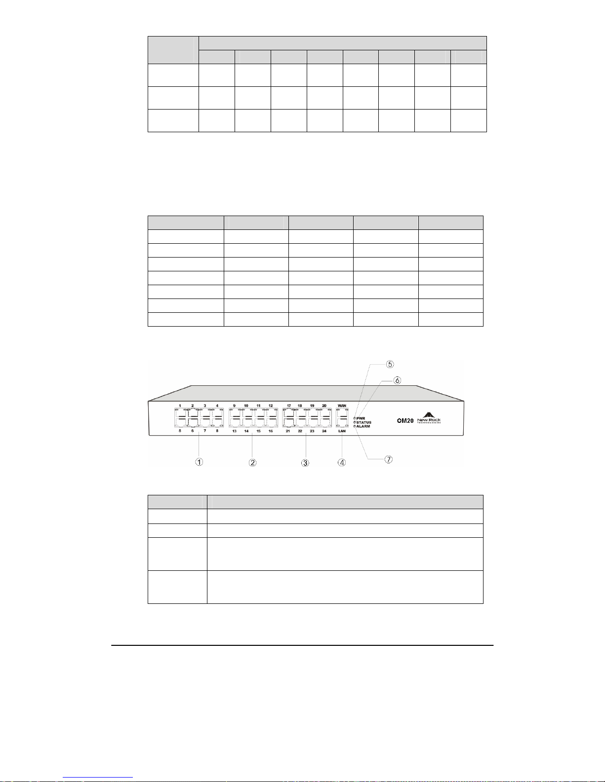
Figure 1-2 OM10 Back Panel
Table 1-4 Description of OM10 back panel
# Description
① Power interface, 5-9 VDC input
② 10/100 Ethernet interface, RJ45
③ Analog line (FXS) or analog trunk (FXO) interface
Table 1-5 Configuration Description of Analog Extension Interfaces for OM10
RJ11 Interface Configuration
OM10
Models
1 2 3 4 5 6 7 8
OM10-4S
Line 1 Line 2 Line 3 Line 4 NA NA NA NA
OM10-8S
Line 1 Line 2 Line 3 Line 4 Line 5 Line 6 Line 7 Line 8
Page 12
Shanghai New Rock Technologies Inc. Page12/75
RJ11 Interface Configuration
OM10
Models
1 2 3 4 5 6 7 8
OM10-4FXO
Trunk
Line 1
Trunk
Line 2
Trunk
Line 3
Trunk
Line 4
NA NA NA NA
OM10-8FXO
Trunk
Line 1
Trunk
Line 2
Trunk
Line 3
Trunk
Line 4
Trunk
Line 5
Trunk
Line 6
Trunk
Line 7
Trunk
Line 8
OM10-4S/4
Line 1 Line 2 Line 3 Line 4
Trunk
Line 1
Trunk
Line 2
Trunk
Line 3
Trunk
Line 4
1.3.2 OM20
Designed with a 1U high and 19–inch wide compact chassis, OM20 is suitable for installation in a
standard cabinet. It has a built-in 110-220V power module. OM20 uses RJ45 for the interface socket
of analog lines and trunks. OM20 supports the following types of configuration:
Table 1-6 OM20 Configuration
Models Local extension Analog trunk SIP extensions SIP trunks
OM20-16S 16 0 60 20
OM20-24S 24 0 60 20
OM20-16FXO 0 16 60 20
OM20-8S/8 8 8 60 20
OM20-12S/4 12 4 60 20
OM20-16S/8 16 8 60 20
OM20-20S/4 20 4 60 20
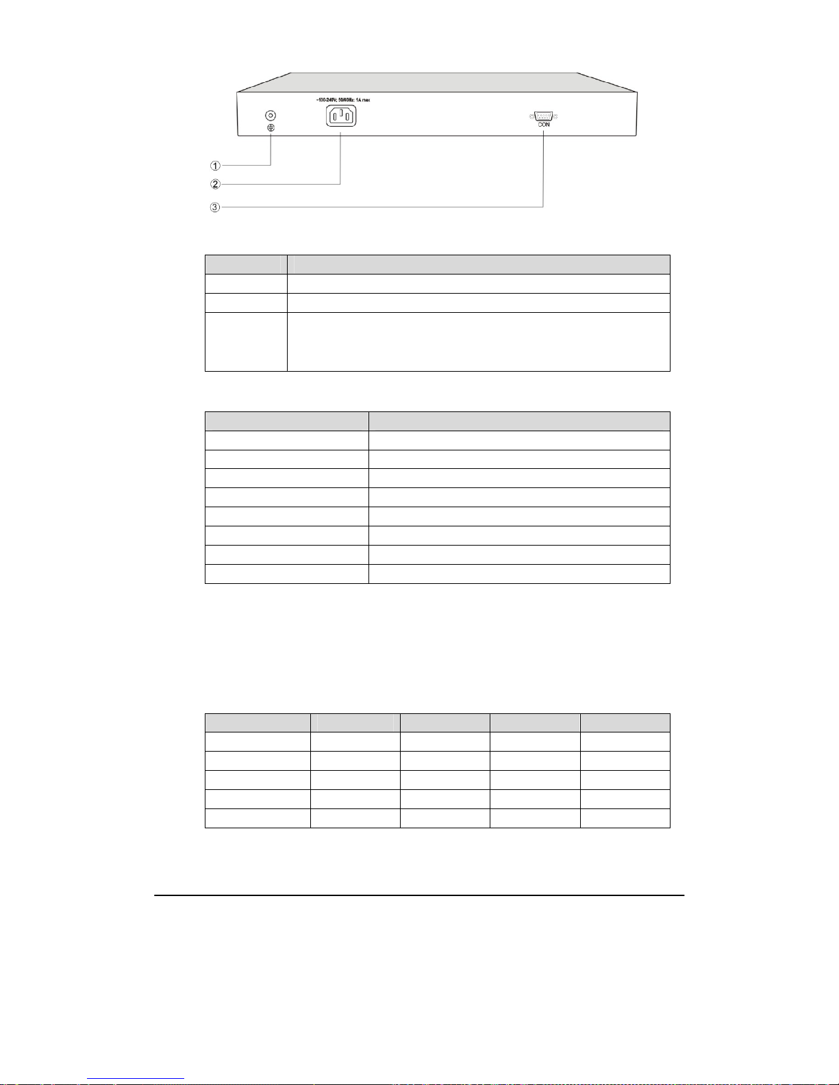
Figure 1-3 OM20 Front Panel
Table 1-7 Description of OM20 Front Panel
# Description
①
Offer the first 8 analog line interfaces (FXS or FXO),interface type is RJ45.
② Offer 9th-16th analog line interfaces (FXS or FXO), interface type is RJ45.
③
Offer 17
th
-24th analog line interfaces (FXS or FXO), interface type is RJ45.
When the total system capacity of OM20 is 16 lines, these interfaces will not
be provided.
④
One 10/100 Ethernet uplink interface (WAN) and one 10/100 Ethernet user
interface (LAN), interface type is RJ45. The uplink interface is used for calls
and management. The user interface is reserved for future use.
Page 13

Shanghai New Rock Technologies Inc. Page13/75
# Description
⑤、⑥、⑦
Three indicators of PWR, STATUS and ALARM represent the power, status
and alarm respectively. Specific meanings of these indicators are described in
Table 1-10.
Table 1-8 Pins and Indicators for FXS and FXO of OM20
Pin LED
1 2 3 4 5 6 7 8 Yellow Green
NC NC NC RING TIP NC NC NC
Interface
Type
Interface
Status
Note: The yellow LED on RJ45 socket works only in the mixed FXS/FXO type configuration of OM.
The yellow LED light on indicates the interface is FXO type, and the yellow light off indicates the
interface is FXS type. In an configuration with only FXS ports or FXO ports, the yellow LED
remains off.
Table 1-9 for Pin and Indicator Table of Ethernet Ports
Pin LED
1 2 3 6 Yellow Green
TX+ TX- RX+ RX-
Connection
Status
Activity
Status
Table 1-10 Indicators of OM20
Mark Function Status Description
Green Power on
PWR
Power
Indication
Off Power off
Off System locked and inactive
Green
Flash
In normal operation
Constant
Red
System in the process of power up and not in the
normal operation mode
STATUS
Status
Indication
Red Flash
System in a diagnostic mode and able to execute
only limited operation
Green No alarms
Red Flash New alarms occurred but not confirmed
ALARM
Alarm
Indication
Red
Alarms existed and all alarm information
confirmed
After normal startup of OM20, three indicators of PWR, STU and ALM on the front panel have
been found to turn green, then STATUS (STU) and ALARM (ALM) indicators turning from
green into red indicating the equipment has detected IP address conflicts.
Page 14
Shanghai New Rock Technologies Inc. Page14/75
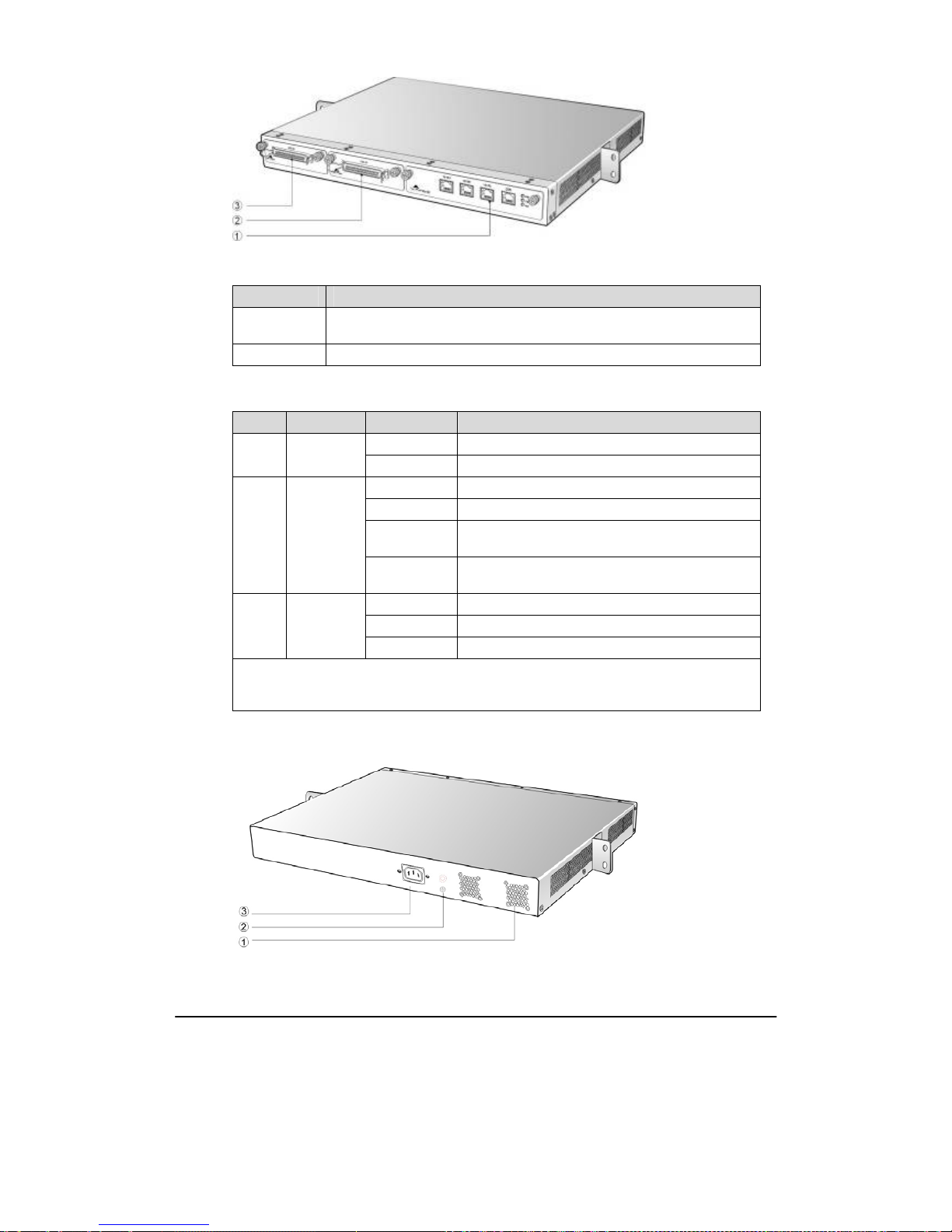
Figure 1-4 OM20 back panel
Table 1-11 Description of OM20 Back Panel
# Description
① Ground pole
② AC power input socket, 100-240 VAC voltage input.
③
The configuration interface (CON) is used for local management and
debugging. It connects with RS232 port on a computer, and local PCs can
establish a connection with OM20 through an emulator on the configuration
terminal. Table 1-12 describes the interface properties.
Table 1-12 Properties of OM20 CON Port
Properties Description
Connector DB9
Number of interface 1
Interface standard RS232
Baud rate 38400
Data bit 8
Parity check No
Stop bit 1
Traffic control No
1.3.3 OM100
Designed with a 1U high and 19-inch wide compact chassis and a swappable modular structure,
OM100 offers flexible on-site configuration and replacement. The interface card of OM100 uses a
Champ50-type socket and is connected to the distribution panel in equipment room using a 25-pair
cable supplied with the unit. OM100 supports the following types of configuration:
Table 1-13 OM100 Configuration
Models Local extension Analog trunk SIP extensions SIP trunks
OM100-48S 48 0 60 60
OM100-32FXO 0 32 60 60
OM100-16S/16 16 16 60 60
OM100-32S/4 32 4 60 60
OM100-32S/8 32 8 60 60
Page 15
Shanghai New Rock Technologies Inc. Page15/75
Figure 1-5 OM100 Front Panel
Table 1-14 Description of OM100 Front Panel
# Description
①
Main control module. It offers one 10/100 Ethernet port and one configuration
interface (CON).
② and ③ Two interface slots, and each can contain one desired type interface card.
Table 1-15 Indicators of OM100
Mark Function Status Description
Green Power on
PWR
Power
indication
Off Power off
Off System locked and inactive
Green flash In normal operation
Constant red
System in the process of power up and not in the
normal operation mode
STU
Status
indication
Red flash
System in a diagnostic mode and able to execute
limited operation
Green No alarms
Red flash New alarms occurred but not confirmed
ALM
Alarm
indication
Red Alarms existed and all alarm information confirmed
After normal startup of OM100, three indicators of PWR, STATUS (STU) and ALARM (ALM)
on the front panel have been found to turn green, and then ALARM (ALM) indicator turning
from green into red indicating the equipment has detected IP address conflicts.
Figure 1-6 OM100 Back Panel
Page 16

Shanghai New Rock Technologies Inc. Page16/75
Table 1-16 Description of OM100 Back Panel
# Description
① Two cooling fans
② Ground pole
③
AC power socket, 100-240 VAC voltage input.
1.3.4 OM200
Designed with a 1U high and 19-inch wide compact chassis with swappable modular structure of
interfaces, OM200 can be scalable to have an expansion chassis which holds two interface cards. The
interface card of OM200 use RJ45 sockets and they are connected to the distribution panel of
equipment room using a CAT-5 Ethernet cable to offer flexible user interface configuration.
The main chassis of OM200 can hold two interface cards which enable to flexibly configure the
number of FXS and FXO ports,and each card equips up to 24 ports. The expansion chassis can also
hold two 24-port interface cards which enable to flexibly configure the number of FXS and FXO
ports. OM200 dual-chassis system can provide up to 96 ports. It supports the following
configurations:
Table 1-17 OM200 Configuration
Models Local extension Analog trunk SIP extensions SIP trunks
OM200-48S 48 0 120 80
OM200-72S 72 0 120 80
OM200-96S 96 0 120 80
OM200-24FXO 0 24 120 80
OM200-48FXO 0 48 120 80
OM200-72FXO 0 72 120 80
OM200-96FXO 0 96 120 80
OM200-40S/8 40 8 120 80
OM200-64S/8 64 8 120 80
OM200-88S/8 88 8 120 80
OM200-36S/12 36 12 120 80
OM200-60S/12 60 12 120 80
OM200-84S/12 84 12 120 80
OM200-32S/16 32 16 120 80
OM200-56S/16 56 16 120 80
OM200-80S/16 80 16 120 80
OM200-28S/20 28 20 120 80
OM200-52S/20 52 20 120 80
OM200-76S/20 76 20 120 80
OM200-24S/24 24 24 120 80
OM200-48S/24 48 24 120 80
OM200-72S/24 72 24 120 80
OM200-44S/28 44 28 120 80
OM200-68S/28 68 28 120 80
OM200-40S/32 40 32 120 80
Page 17
Shanghai New Rock Technologies Inc. Page17/75
Models Local extension Analog trunk SIP extensions SIP trunks
OM200-64S/32 64 32 120 80
OM200-36S/36 36 36 120 80
OM200-60S/36 60 36 120 80
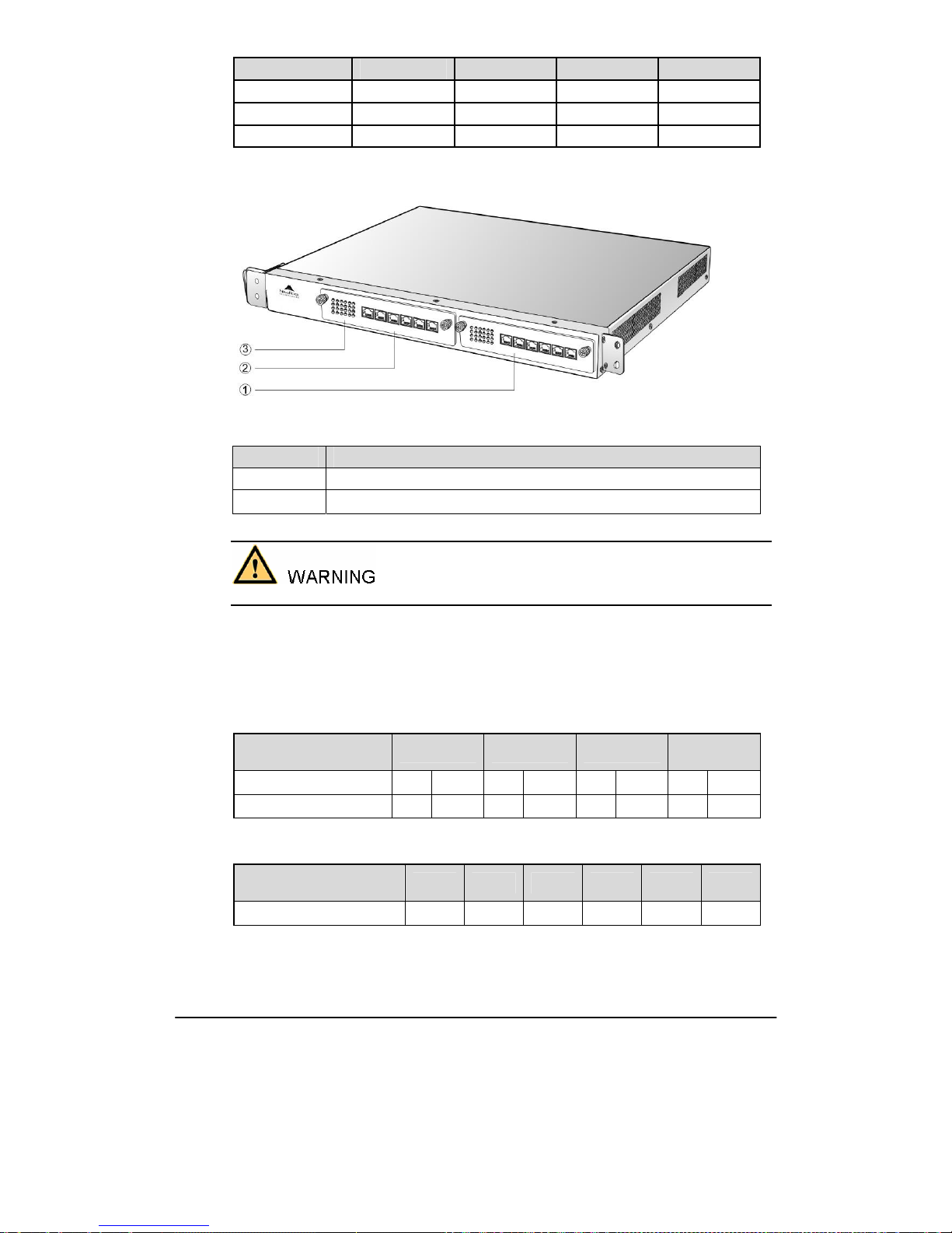
Figure 1-7 OM200 Front Panel
Table 1-18 Description of OM200 Front Panel
# Description
① and ② Two interface slots; each can contain one 24-port interface card.
③ Matrix of 6×4 LED status indicator on interface card
Do not plug and remove the interface cards of OM200 when equipment is powered on.
Each RJ45 socket has 8 pins leading out 4 pairs of analog telephone or trunk lines in agreement with
the pair specifications for Ethernet interfaces, whose corresponding relations can be seen in the table
below. CAT-5 cables are used to connect the interface card and distribution panel in equipment
installation. Standard RJ11 telephone lines can be used to plug in a RJ45 socket. The telephone/trunk
lines are connected to the 3rd pair of pins for simple call test.
Table 1-19 Pin Specifications for OM200 RJ45 Socket Port
Numerical sequence of
line
1st Pair 2nd Pair 3rd Pair
4th Pair
Pin No. of RJ45 contact 1 2 3 6 4 5 7 8
Corresponding RJ11 TIP1 RING1 TIP2 RING2 TIP3 RING3 TIP4 RING4
Table 1-20 Corresponding Relation Between OM200 RJ45 Socket and Line Number
RJ45 socket No. (from left to
right)
1 2 3 4 5 6
Line No. of this card
1 ∼ 4 5 ∼ 8 9 ∼ 12 13 ∼ 16 17 ∼ 20 21 ∼ 24
There is a 6 × 4 LED indicator matrixes on the left side of interface board. Each row of LED
indicator matrixes matches four telephone lines on a RJ45. The first row on the left matches Line 1-4
Page 18
Shanghai New Rock Technologies Inc. Page18/75
respectively from top to bottom, the first row on the right matches Line 21-24 respectively from top
to bottom, and the middle rows in the same manner .
LED indicators are used for multiple purposes as follows
z
Line status indication: This is the most common mode during normal use of equipment. In this
mode, if a line is idle, the indicator corresponding to it goes off; if a line is in call or in use status
(such as ringing, offhook and caller ID transmission of FXS interface, ringing, offhook and caller
ID detection of FXO interface) the indicator corresponding to it goes on.
z
Line type indication: This is the mode for installation of equipment or wiring check. This mode
can be entered by disconnecting the network interface (two Ethernet interfaces on the host are
disconnected) when connecting lines at installation stage, or through interface control when the
check is made during normal operation. After entering the mode, LED constant on indicates that
the corresponding line is equipped and is an analog telephone line, LED flashing indicates that
the corresponding line is equipped and is an analog trunk lines; LED off indicates that the
corresponding line is not equipped or is faulty.
z
System operation status indication: This is the mode for displaying information on system
operation of equipment in specific conditions. Usually, this mode is entered when some prompts
are required to give operator during equipment startup, diagnosis or operation. In this mode, LED
flashes to display numbers, letters or other patterns in matrix. Please refer to the Appendix:
Check List for Operation Status Indication of OM200 System.
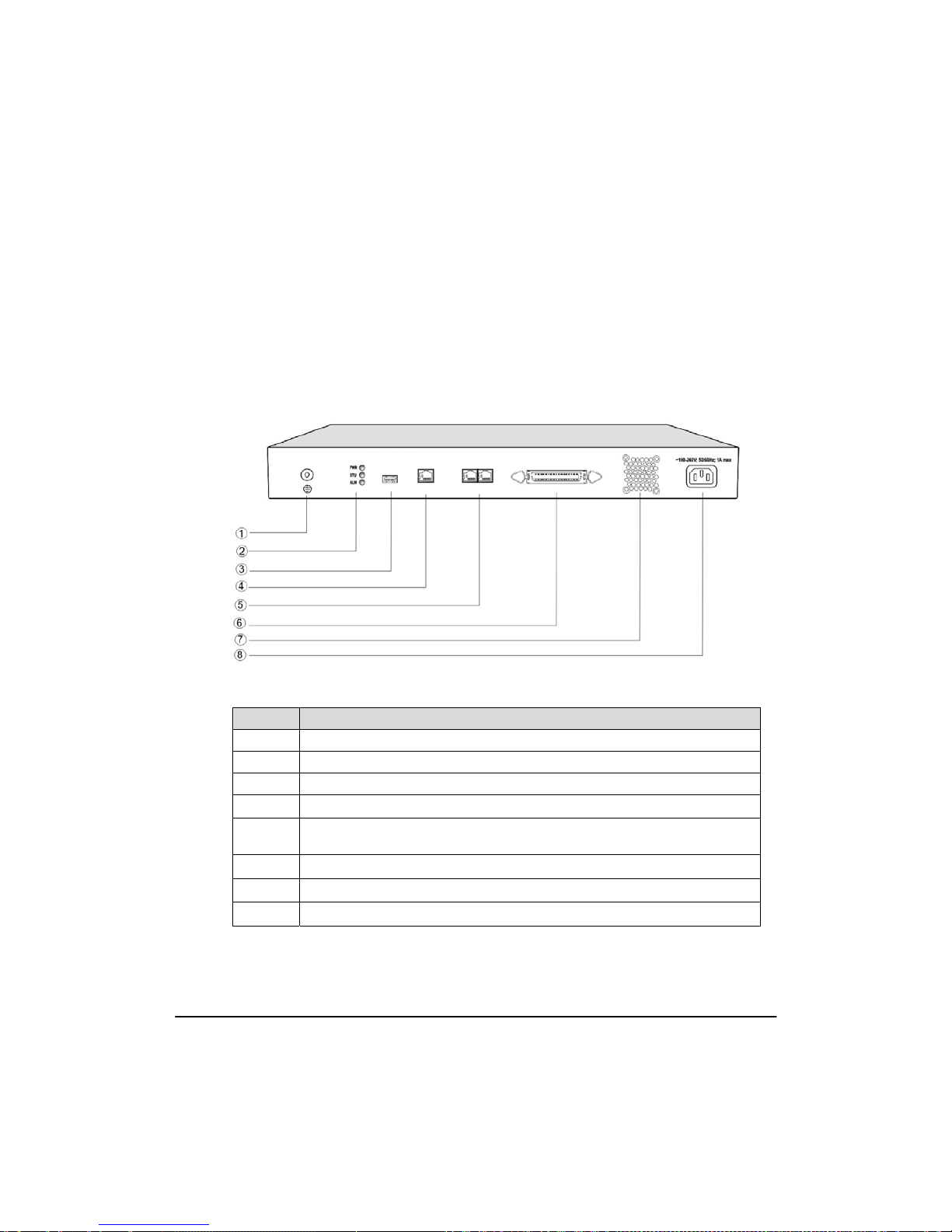
Figure 1-8 OM200 Back Panel
Table 1-21 OM200 Back Panel
# Description
① Ground pole
② Indicator, see Table 1-22 for description.
③ USB interface, reserved for future use.
④
Configuration interface (CON), used for local management and debugging.
⑤
Two Ethernet interfaces: ETH1 and ETH2, only ETH1 has been set when the
equipment is delivered from factory, default IP address: 192.168.2.240
⑥
Connection interface of expansion chassis
⑦
Cooling fan
⑧
AC power socket, 100V-240 VAC voltage input.
Page 19
Shanghai New Rock Technologies Inc. Page19/75
Table 1-22 Meanings of OM200 Indicators
Mark Function Status Description
Green Power on
PWR
Power
indication
Off Power off
Off System locked and inactive
Green flash In normal operation
Constant red
System in the process of power up and not in the
normal operation mode
STU
Status
indication
Red flash
System in a diagnostic mode and able to execute
limited operation
Green No alarms
Red Flash New alarms occurred but not confirmed
ALM
Alarm
Indication
Red
Alarms existed and all alarm information
confirmed
After normal startup of OM200, the indicator displaying letter C flash indicates that OM200 has
detected IP address conflicts.
OM200 single-chassis system can provide up to 48-line with different analog line type configuration
combinations, and OM200 dual-chassis system (main chassis and expansion chassis) can provide
maximum of 96-line with different analog line type configuration combination. OM200 dual-chassis
system is a logical integrated system formed by adding an expansion chassis and interface cards on
top of the single chassis system. An expansion cable is required to connect the two chassises, and the
operation of the main chassis will not be affected when connecting the expansion cable, suitable for
on-site capacity expansion. The system resources (e.g. number of concurrent calls) are determined by
the main chassis, so users who are planning to expand capacity should take into account the needs for
future system resources when initially ordering the single-chassis system, to support the smooth
capacity expansion and upgrade.
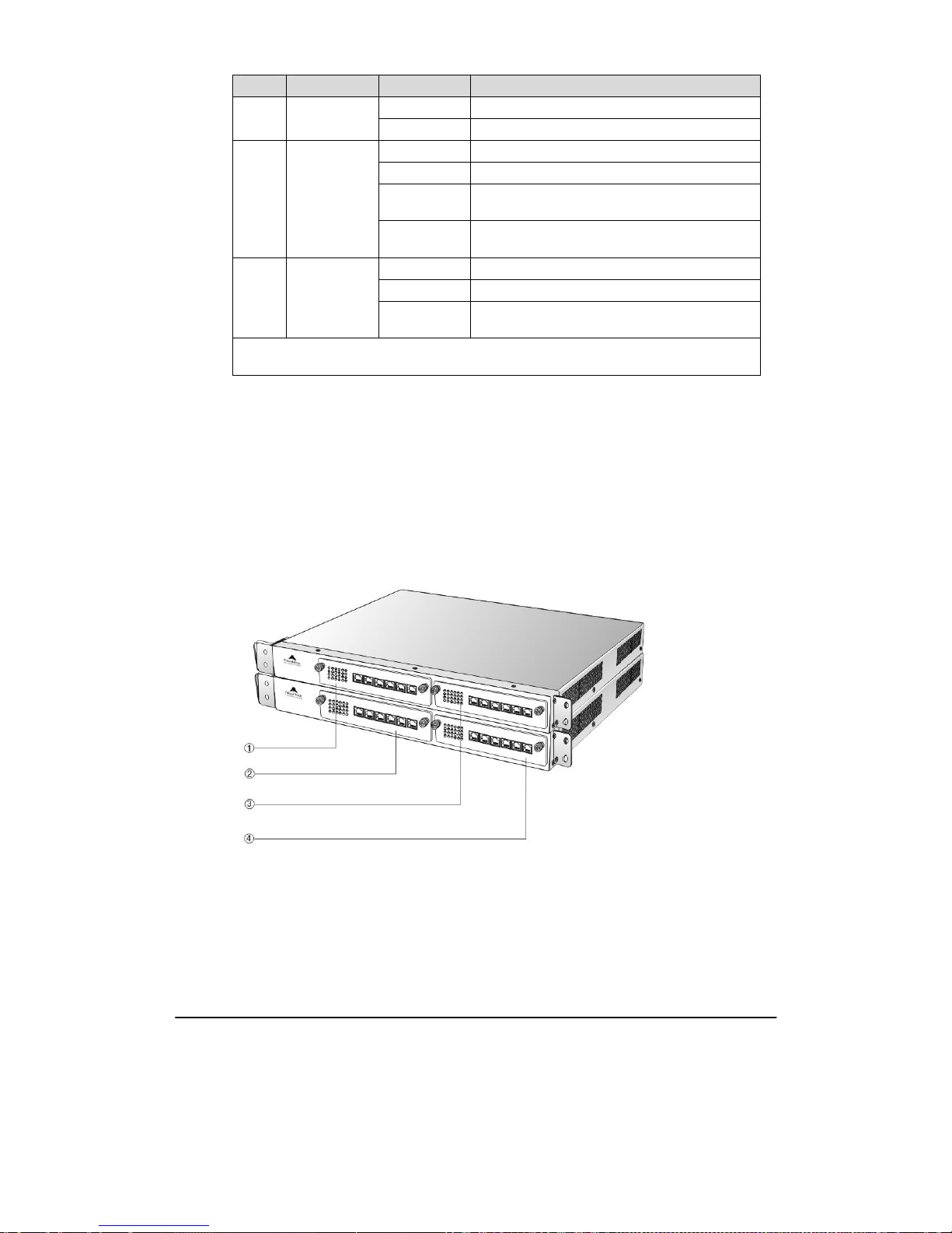
Figure 1-9 Schematic Diagram for Front Panel of OM200 Dual-Chassis System
Numbering definition of system interface slots: On the left side of main chassis is #1 slot (marked
with ① in Figure 1-9), on the right side of main chassis is #2 slot (marked with ③ in the Figure
1-9), on the left side of expansion chassis is #3 slot (marked with ② in the Figure 1-9), and on the
right side of expansion chassis is #4 slot, marked with ④ in Figure 1-9).
Page 20

Shanghai New Rock Technologies Inc. Page20/75
Figure 1-10 Schematic Diagram for Back Panel of OM200 Dual-Chassis System
OM200 dual-chassis system consists of a main chassis and an expansion chassis. Seen from the front,
it is different from the screen-printed mark: main chassis printed with "OM200-MAIN" mark and
expansion chassis printed with "OM200-EXT" mark. Seen from the back, the difference is obvious:
expansion chassis does not have status indicator, USB interface, CON interface and two Ethernet
interfaces. The main and expansion chassises have their own independent power supply and cooling
system, which are connected by a 36-core flat cable to form a logical integrated system.
To ensure the reliable communications between two chassises and reduce EMI interference, the
communication cable for connecting two chassises should be short. OM200 dual-chassis system must
be placed adjacently in installation (users who plan to expand capacity should reserve a space for
expansion chassis during the initial installation of single chassis), the up or lower position is not
strictly required for the chassises.
Page 21

Shanghai New Rock Technologies Inc. Page21/75
2 Parameter Setting
2.1
Login to Web-based Utility
2.1.1 Obtain OM IP Address
OM10 and OM20 start DHCP service by default, and automatically obtain an IP address on the LAN;
users can use the factory default IP address if it is unable to be obtained (e.g. when connected directly
with a computer).
OM100 and OM200 use a static IP address by default.
Table 2-1 Default IP Address of OM
Type Default DHCP Service Default IP Address
OM10 Enabled 192.168.2.218
OM20 Enabled 192.168.2.228
OM100 Disabled 192.168.2.240
OM200 Disabled 192.168.2.240
z
DHCP Used in Network
Users can dial "# #”to obtain the current IP address of the device and version information of
firmware using the telephone connected to a FXS port after the equipment is powered on.
If the OM is only configured with FXO ports for analog trunks without FXS ports (e.g.
OM10-4FXO or OM20-24FXO), users can dial into the OM by connecting a PBX extension line
or CO line to a FXO port, and press "# #" to obtaining the current IP address of the device and
version information of firmware.
z
Fixed IP Address Used
¾ If the DHCP service on the network is not available or the OM is directly connected with a
computer, the OM will use the factory default IP address.
¾ A user could fail to log in with the default IP address if the IP address of user’s computer
and the default OM IP address are not at the same network segment. It is recommended that
the IP address of user's computer is changed to be identical with the same network segment.
For example, if the OM IP address is 192.168.2.240, it is recommended to set the
computer’s IP address to any address at the network segment of 192.168.2.XXX.
z
PPPoE Used
In “Basic Configuration> Network Configuration”, the OM will automatically obtain the WAN
address returned by access network after PPPoE service is started and user name and password
are set. Users can dial “# #”on the OM to receive the IP address and version information of
firmware.
z
IP Address Port Configuration of Equipment
It is typically required to fill in the port when using DDNS since the router possibly maps to a
different port in port mapping.
Normally, it is unnecessary to fill in the port value.
Page 22
Shanghai New Rock Technologies Inc. Page22/75
2.1.2 Logon
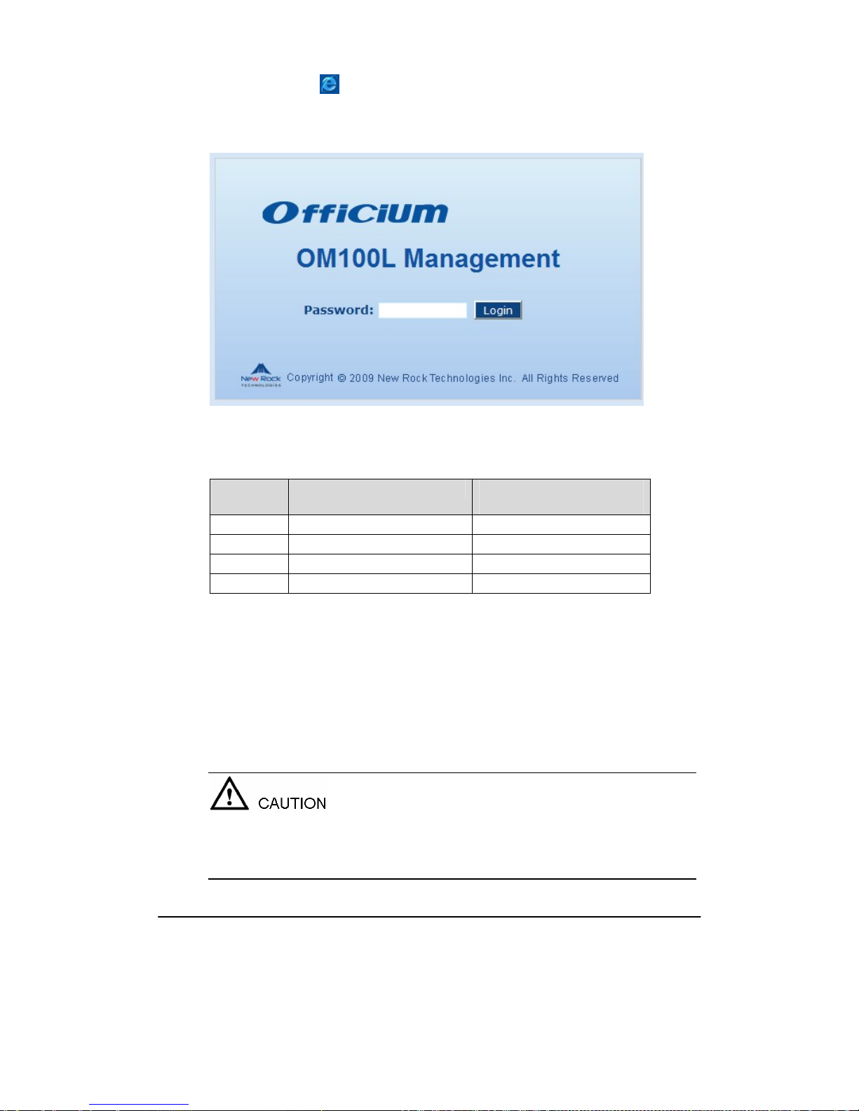
Double-click the icon to open IE browser, and enter the OM IP address in the browser address
bar (e.g. 192.168.2.218). You can logon to the web-based utility by entering a password on the login
interface.
Figure 2-1 Login Interface of OM Web-based Utility
Logon users are classified into “administrator” and “operator”. The default password is seen Table
2-2. The password is shown in a cipher for safety.
Table 2-2 Default Passwords of OM
Type Default Operator Password Default Administrator Passwords
(lowercase letters required)
OM10 operator admin
OM20 operator admin
OM100 operator admin
OM200 operator admin
z
The administrator can browse and modify all configuration parameters, and modify login
passwords.
z
The operator can browse and modify part of configuration parameters.
The OM allows multiple users to log in:
¾ The aadministrator has permission for modification and the operator has permission for
browsing;
¾ When multiple users with same level of permission log in, the first has permission for
modification, while the others only have permission for browsing.
The system will confirm timeout if users do not conduct any operation within 10 minutes after login.
They are required to log in again for continuing operations.
Upon completion of configuration, click "Logout" button to return to the login page, so as not to
affect the login permission of other users.
Page 23
Shanghai New Rock Technologies Inc. Page23/75
2.2
Buttons Used on OM Web-based Utility
“Submit” and “Refresh” buttons are at the bottom of configuration interface.
z
Submit” Button: Submit configuration information. Users click “Submit” button after completion
of parameter configuration on a page. A success prompt will appear if configuration information
is accepted by the system; if a “The configuration takes effect after the system is restarted”dialog
box appears, it means that the parameters are valid only after system restart; it is recommended
that users press the “Rstart” button on the “Tool” page to validate the configuration after
changing all parameters to be modified.
z
“Refresh”: Cancel changed operation that has not been submitted.
2.3
Basic Configuration
2.3.1 Status
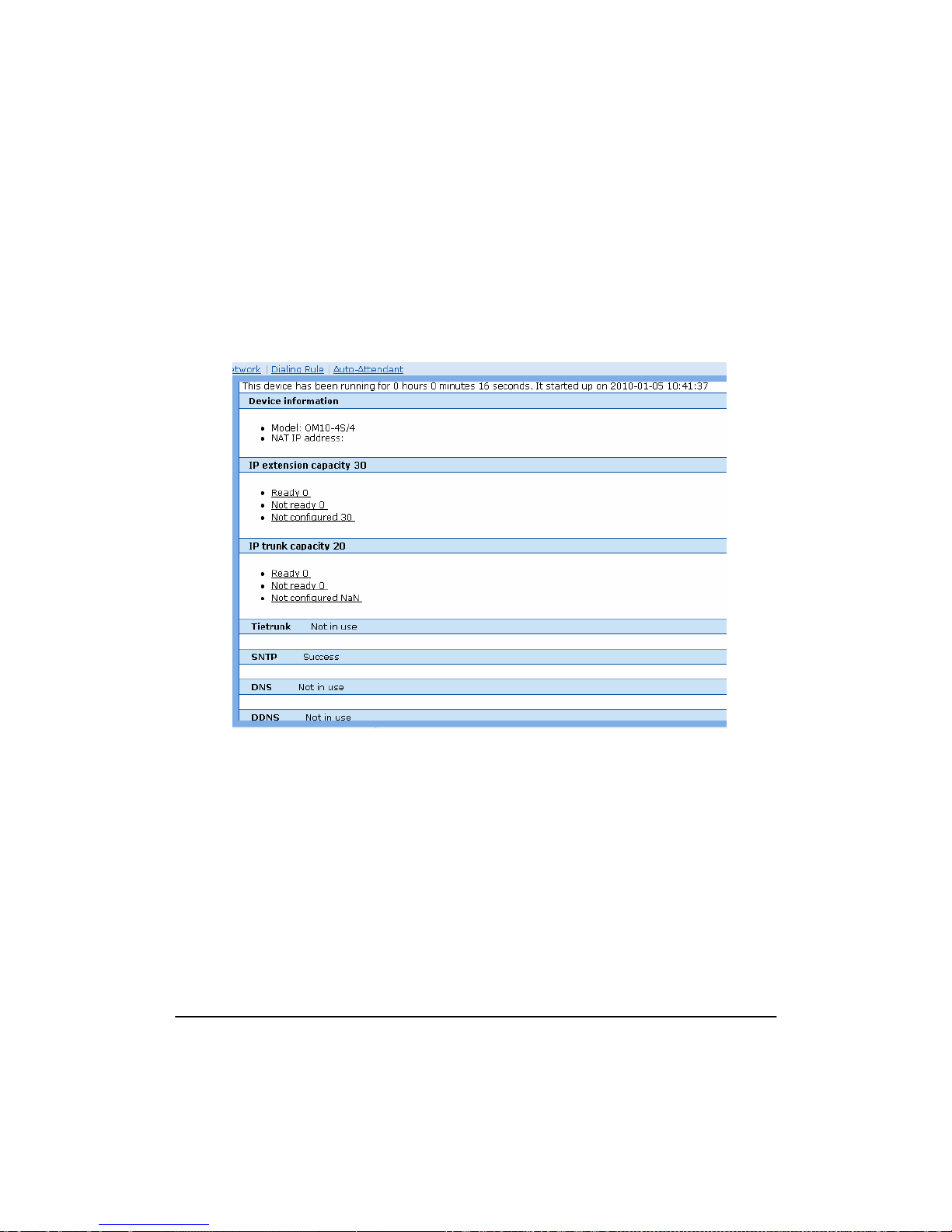
After login, click “Basic > Status” tab to open the status interface.
Figure 2-2 Status Interface
2.3.2 Network Configuration
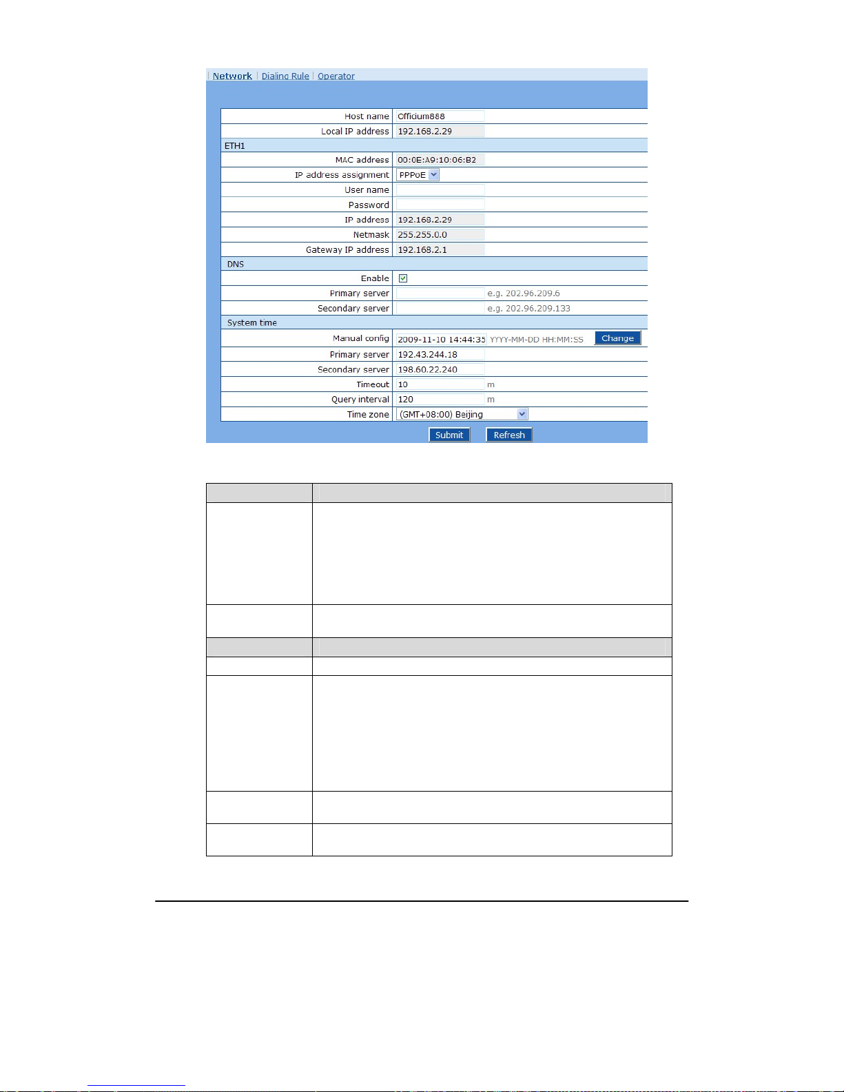
After login, click “Basic > Network” tab to open the configuration interface.
Page 24
Shanghai New Rock Technologies Inc. Page24/75
Figure 2-3 Network Configuration Interface
Table 2-3 Configuration parameter of Network
Name Description
Host name
This is the equipment name of OM. The default values of OM10, OM20,
OM100 and OM200 are Officium10, Officium20, Officium100 and
Officium200 respectively. Users can set a different name for each OM to
distinguish from each other according to the deployment plan.
A host name can be a maximum of 48 characters, either letters (A-Z or
a-z), numbers (0-9) and minus sign (-). It may not be null or space, and it
must start with a letter.
Logical IP address
This parameter only exists in OM100 and OM200, used to display the
actual OM IP address in use.
ETH
MAC address Display the MAC address of OM.
IP address
assignment
Methods for obtaining an IP address
z Fixed: Static IP address is used;
z DHCP: Activate DHCP service and use the dynamic host configuration
protocol (DHCP) to allocate IP addresses and other network
parameters;
z PPPoE: PPPoE s e rvice is used.
User name
Enter an authentication user name if PPPoE service is selected, and there
is no default value.
Password
Enter an authentication password if PPPoE service is selected, and there
is no default value.
Page 25

Shanghai New Rock Technologies Inc. Page25/75
Name Description
IP address
If “Static” or “DHCP” is selected for the network type but an address
fails to be obtained, the OM will use the IP address filled in here. If the
OM obtains an IP address through DHCP, the system will display the
current IP address automatically obtained from DHCP by the OM. This
parameter must be set due to no default value.
Netmask
The subnet mask is used with an IP address. When the OM uses a static
IP address, this parameter must be entered; when an IP address is
automatically obtained through DHCP, the system will display the subnet
mask automatically obtained by DHCP. This parameter must be set due
to no default value.
Gateway IP
address
LAN gateway IP address where the OM is located. When the OM obtains
an IP address through DHCP, the system will display the LAN gateway
address automatically obtained through DHCP. This parameter must be
set due to no default value.
DNS
Enable Activate DNS service.
Primary Server
If DNS service is activated, the network IP address of preferred DNS
server must be entered, and there is no default value.
Secondary Server
If DNS service is activated, the network IP address of standby DNS
server can be entered here. It is optional and there is no default value.
SNTP
Manual config The system will use the time set here if time server doesn’t work.
Primary Server
Enter the IP address of preferred time server here. This parameter must be
set due to no default value.
Secondary Server
Enter the IP address of standby time server here. This parameter must be
set due to no default value.
Timeout
Timeout when periodically sending a request for clock synchronization
fails
Query interval Interval of sending a request for clock synchronization to the time server
Page 26

Shanghai New Rock Technologies Inc. Page26/75
Name Description
Time Zone Select a time zone, and the parameter values include:
z (GMT-11:00) Midway Island
z (GMT-10:00) Honolulu. Hawaii
z (GMT-09:00) Anchorage, Alaska
z (GMT-08:00) Tijuana
z (GMT-06:00) Denver
z (GMT-06:00) Mexico City
z (GMT-05:00) Indianapolis
z (GMT-04:00) Glace Bay
z (GMT-04:00) South Georgia
z (GMT-03:30) Newfoundland
z (GMT-03:00) Buenos Aires
z (GMT-02:00) Cape_Verde
z (GMT) London
z (GMT+01:00) Amsterdam
z (GMT+02:00) Cairo
z (GMT+03:00) Moscow
z (GMT+03:30) Teheran
z (GMT+04:00) Muscat
z (GMT+04:30) Kabul
z (GMT+05:30) Calcutta
z (GMT+05:00) Karachi
z (GMT+06:00) Almaty
z (GMT+07:00) Bangkok
z (GMT+08:00) Beijing
z (GMT+09:00) Tokyo
z (GMT+10:00) Canberra
z (GMT+10:00) Adelaide
z (GMT+11:00) Magadan
z (GMT+12:00) Auckland
2.3.3 Dialing Rules
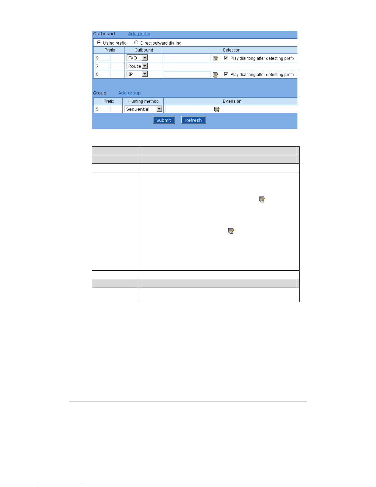
After login, click “Basic > Dialing Rule” tab to open the configuration interface.
Page 27
Shanghai New Rock Technologies Inc. Page27/75
Figure 2-4 Dialing rule configuration interface
Table 2-4 Configuration parameters of dialing plan
Name Description
Outbound
Prefix Used for selecting a trunk for an outgoing call. Value range: 0~9.
Outbound The types of trunk for outgoing calls:
z FXO: Using analog trunks for outgoing calls with the corresponding
prefix. Example: if the prefix of analog trunk is set to 9, users dial 9 to
select an analog trunk for outbound call. Click
to select the
specified analog trunks.
z IP: Using SIP trunks for outgoing calls with the corresponding prefix.
Example: if the prefix of IP trunk is set to 6, users dial 6 to select an
SIP trunk for outbound call. Click
to select the specified SIP
trunks.
z Route: Selecting the trunks according to the routing table.
Note: If an outbound trunk is not specified, the equipment will select any
available trunk.
Selection Used to define outbound line.
Group
Prefix
Used for selecting the group when making an incoming call. Optional
value: 0~9.
Page 28
Shanghai New Rock Technologies Inc. Page28/75
Name Description
Hunting method
z Simultaneous: Set a prefix for a group of extensions. When the prefix
is pressed in an incoming call, the OM rings idle extensions in the
group concurrently; when an extension receives the call, the OM will
stop ringing of other extensions in the group. Click
to select the
extensions for the group. These selected extension lines will ring
simultaneously when users dial this prefix.
z Sequential: Set a prefix for a group of extensions. When the prefix is
pressed in an incoming call, OM distributes the call to the idle
extension in a sequential order. Click
to select the extensions for
the group.
z Circular: Set a prefix for a group of extensions. When the prefix is
pressed in an incoming call, OM distributes the call to the idle
extension in a circular order. Click
to select the extensions for the
group.
Selection Used to define line for distributing incoming calls.
Direct Outward
Dialing
Used to set direct outward dialing. When choosing “Direct Outward
Dialing”, you can dial the external phone number without any prefix to
reach it. On the other hand, you need to add “*” prefix to an extension
number when making an internal call.
2.3.4 Auto Attendant
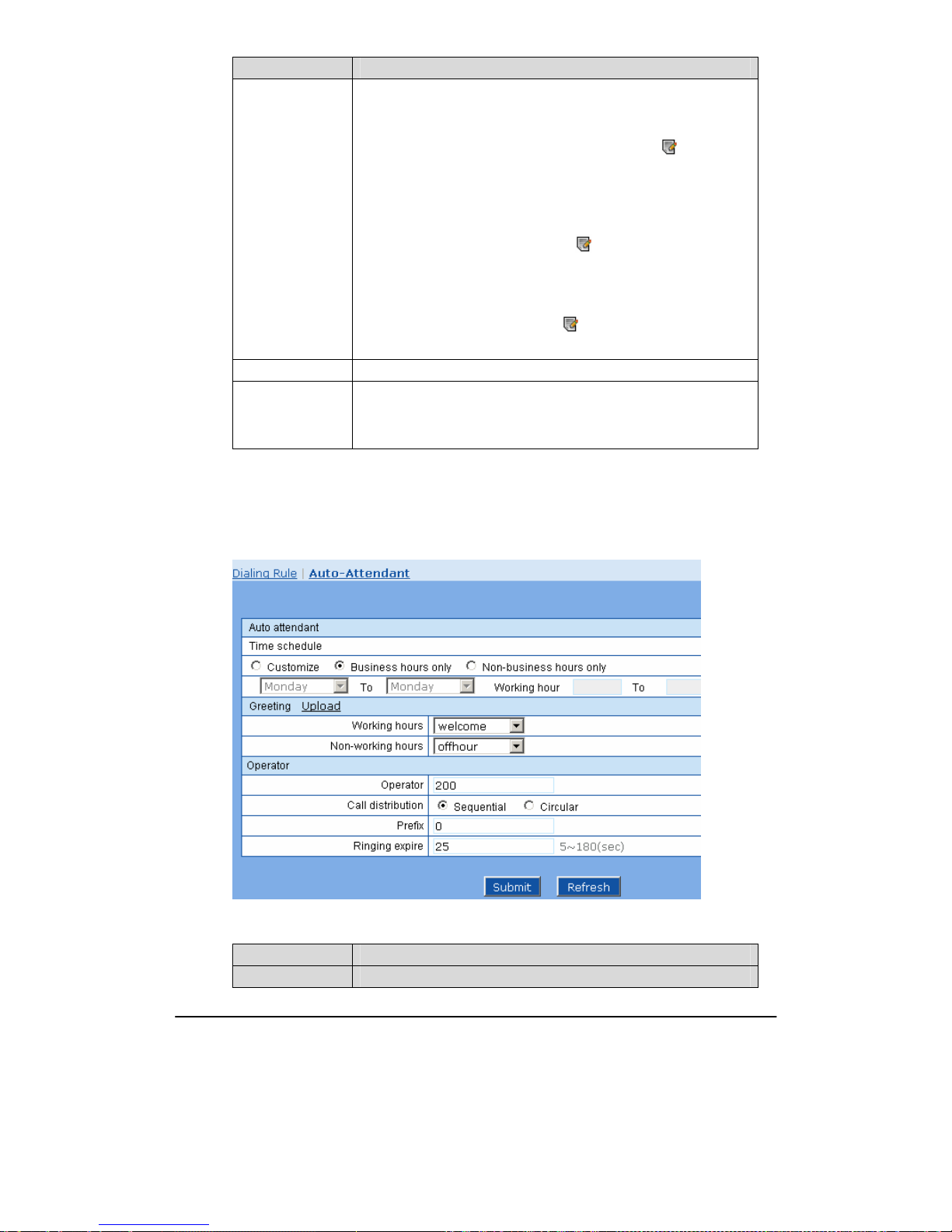
After login, click “Basic > Auto Attendant” tab to open the configuration interface.
Figure 2-5 Configuration interface of Auto Attendant
Table 2-5 Configuration Parameters of Auto Attendant
Name Description
Auto Attendant
Page 29
Shanghai New Rock Technologies Inc. Page29/75
Name Description
Time Schedule
The IVR will use different voice prompts based on “working hours” and
“non-working hours”.
Setting of time schedule:
z Customize: Set the start day and end day of working for each week and
the start time and end time of working for each day according to the
working hours of company.
z Business hours only: Set all time schedules to be working hours. It is
generally used for organizations providing 24-hour service.
z Non-business hours only: Set all time schedules to be non-working
hours. It is generally used for holidays or out-of-business stage.
Greeting
Set the greetings of auto attendant for working hours and non-working
hours.
Operator Set up to 5 operator extensions.
Operator Define extensions corresponding to operators with a maximum of 5.
Call Distribution
The caller may select an attendant to answer the call. The OM provides
two call distributions methods:
z Sequential: Select idle extensions in sequential order.
z Circular: Select idle extensions in a circular order.
These call distributions will perform the same if there is only one
operator extension.
Prefix Used for dialing the operator. Optional value: 0~9.
Ringing Expire
This parameter defines the no answer timeout for non-operator
extensions. After the timeout, the call will be returned will be returned to
the operator. The unit is second.
2.4
Extension
2.4.1 Analog Ext.
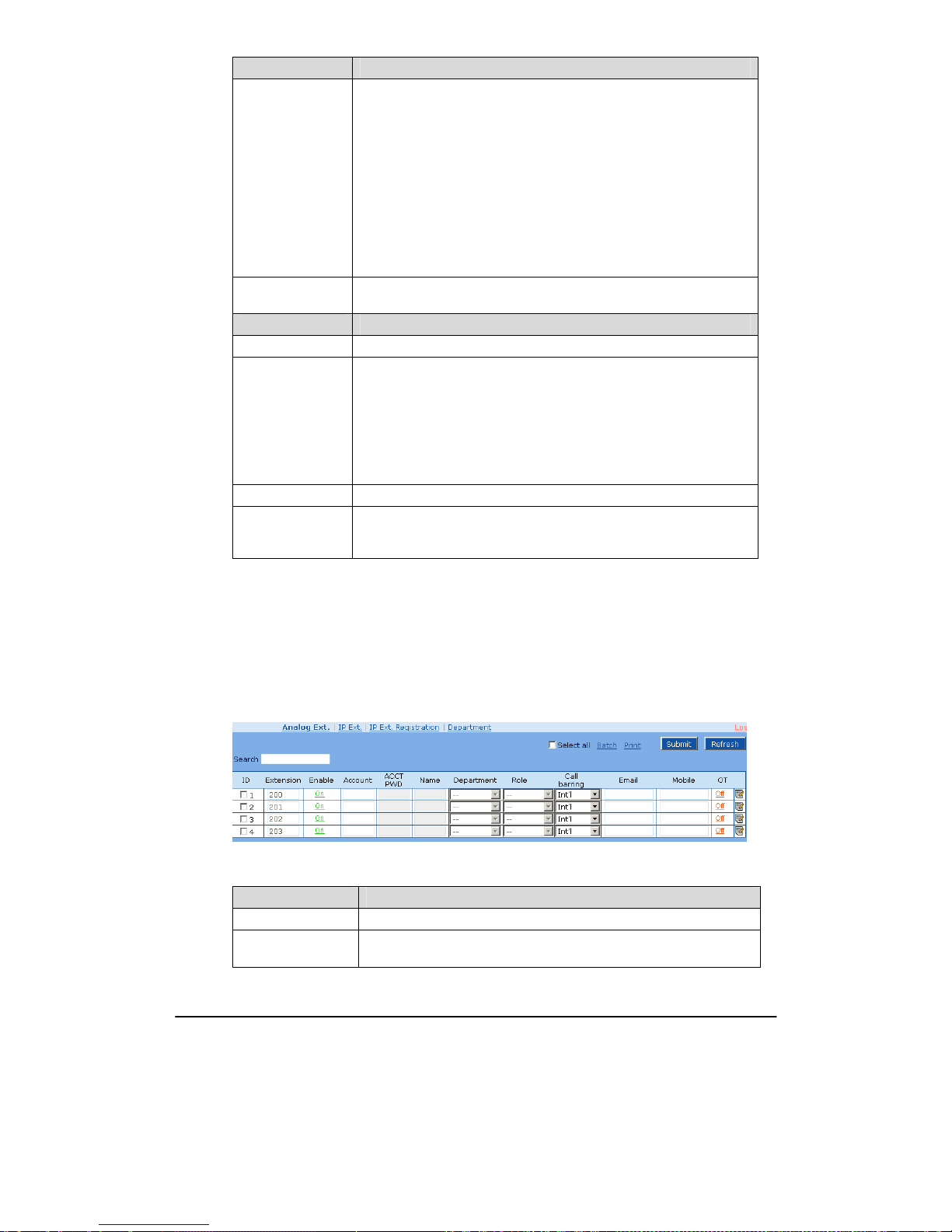
After login, click “Extension > Analog Ext.” tab to open the configuration interface.
Figure 2-6 Basic configuration interface of analog extension
Table 2-6 Basic configuration parameter of analog extension
Name Description
ID Port ID of analog extension (read-only).
Extension
Assign the extension number for this analog extension. The default value
is not null and its numbering starts with 200.
Page 30

Shanghai New Rock Technologies Inc. Page30/75
Name Description
Enable
Select if the line is set to maintenance status, namely, stop to supply of
power for the line port. In this status, the line fails to be used normally.
The administrator can disable the extension by setting the line to off
status.
Account
Set a user account for logging on to the assistant. It is needed to enable
the account if a department is selected.
ACCT PWD Set a logon password for this account.
Name
User name, which is the same as account name by default. It is not a
mandatory option but only used for monitoring of assistant and operator.
Department
Set a department (group) on this line. It is not a mandatory option but
only used for monitoring of assistant and operator.
Role
Set the role type on this line (including general user, privileged user and
operator)
z User: A user who has permission to use all basic functions except
extension and trunk monitoring.
z Manager: A manager can monitor extension and trunk status in
addition to playing the “general” role. The system can set up to 3
privileged users.
z Attendant: It is an account type specially designed for attendants. It
has no call forwarding and DND but provides setting of call transfer
and corporate prompt tone, can monitor all extensions and trunks and
view all call logs.
Call Barring Set the outbound call barring on this line, including:
z None: Can only receive calls, but cannot make any calls;
z Intercom: Can only make internal calls;
z Local: Can make internal and local calls;
z Domestic: Can make internal, local and domestic long-distance calls;
z Int’l: No restriction.
Email Set an Email bound with this line. This is used for voice mail.
Mobile
Set a mobile number bound with this line. This is used for mobile
extension.
OT
Outbound Transfer. This parameter is used with Call Transfer. Select if
users are barred for outbound call transfer. By default, this is disabled.
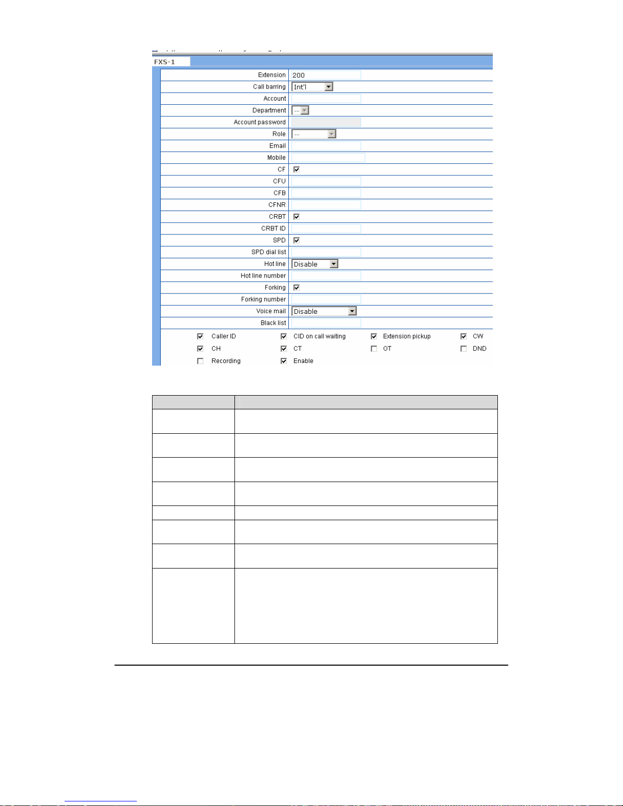
Click
to open the whole configuration interface of analog extension.
Page 31
Shanghai New Rock Technologies Inc. Page31/75
Figure 2-7 Others configuration interface of analog extension
Table 2-7 Others configuration parameter of analog extension
Name Description
CF
Select if Call Forwarding is activated on this line. By default, this is
activated.
CFU
If it is required to forward all incoming calls unconditionally, enter the
new destination number here.
CFB
If it is required to forward an incoming call when it is busy, enter the
new destination number here.
CFNR
If it is required to forward an incoming call when there is no answer,
enter the new destination number here.
CRBT Select if CRBT is activated on this line.
CRBT ID
Set the CRBT number with a valid rang of 0~255, where 0 indicates
disabling CRBT. The default value is 0.
SPD
Select if the Speed dials is activated on this line. By default, this is not
selected.
SPD dial list If the Speed dials is activated on this line, enter the speed dials list.
The abbreviated number consists of max 30 pairs of “abbreviated
number-real number” with an minus sign between them; “abbreviated
number-real number” pairs are separated by “/”; the value range of
abbreviated number is 20 ~ 49. For example:
20-61202700/23-13052475522/30-96961. Users can set the list on a
telephone set and display it here.
Page 32

Shanghai New Rock Technologies Inc. Page32/75
Name Description
Hot Line
Select if the OM is required to automatically dial out the preset hotline
number after offhook. By default, hot line is disabled. It supports two
types:
z Immedia te: Automatically dial out the preset hotline number after
offhook.
z Delayed: Automatically dial out the preset hotline number after
offhook with a time of 5 seconds.
Hot Line Number
After the hotline function is activated on this line, the hotline number
must be entered here.
Forking
Select if the Forking is activated. Forking allows the gateway to initiate a
call to another telephone terminal while ringing on this line terminal, and
the answer by either terminal will end up with ringing of the other
terminal.
Forking Number
Forking allows the OM to initiate a call to another telephone terminal
(eg. the user’s mobile phone) preset by users while ringing on this
extension; and the OM will immediately end up the call on another
terminal when users lift off the hook on either terminal. The
administrator can set numbers corresponding to forking terminals in this
parameter, and users can set it through telephone.
Voice Mail Select if Voice Mail is activated.
Black list
Enter the list of phone numbers which OM should reject. separated with
“,”. e.g.: 02161243400,1305678899
Caller ID
Set if Caller ID display is activated on this line. By default, this is
selected.
Note: In addition to number display, the Caller ID can display the names
of incoming calls as long as terminal equipments support.
CID on call waiting
Select if Caller ID Display is activated on this line during call waiting.
By default, this is not selected.
Extension pickup Select if Pickup is activated on this line.
CW Select if Call Waiting is activated on this line.
CH Select if Call Hold is activated on this line. By default, this is activated.
Note:
If this function is activated, the OM will automatically activate Call
Transfer.
CT
Select if Call Transfer is activated on this line. By default, this is
activated. Example: When A calls B, B picks up the call and transfers it
to C. Note: The Call Hold must be activated before Caller Transfer.
OT
Outbound Transfer. This parameter is used with Call Transfer. Select if
users are barred for outbound call transfer. By default, this is disabled.
DND
Select if “Do Not Disturb” is activated on this line. By default, this is not
selected.
Recording Select if telephone Recording is activated.
Enable
Select if the line is set to maintenance status, namely, stop to supply of
power for the line port. In this status, the line fails to be used normally.
The administrator can disable the extension by setting the line to off
status.
Page 33
Shanghai New Rock Technologies Inc. Page33/75
2.4.2 IP Ext.
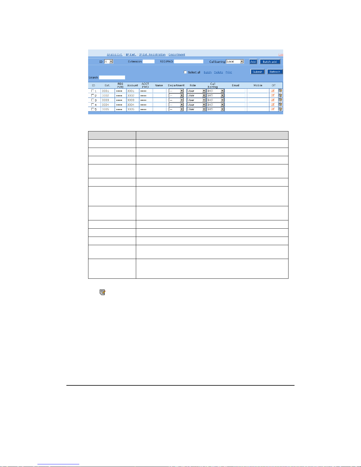
After login, click “Extension > IP Ext.” tab to open the configuration interface.
Figure 2-8 Basic configuration interface of IP extension
Table 2-8 Basic configuration parameter of IP extension
Name Description
ID IP extension line ID, which is automatically created by the system.
Ext. Number assigned to this IP extension. By default, this is null.
REG PWD Registration password registered to the OM by IP extension.
Account
Set a user account for logging on to the assistant. It is needed to enable
the account if a department and a assistant are selected.
ACCT PWD Set a logon password for this assistant account.
Name
Display the user name, which is the same as account name by default. It
is not a mandatory option but only used for monitoring of assistant and
operator.
Department
Set a department (group) on this line. It is not a mandatory option but
only used for monitoring of assistant and operator.
Role Same as analog extension.
Call Barring Same as analog extension.
Email Set an Email bound with this line. This is used for voice mail.
Mobile
Set a mobile number bound with this line. This is used for mobile
extension.
OT
Select if Outbound Transfer is activated on this line. By default, this is
disabled. When this function is mainly used for call forwarding and
caller transfer, if this lined can be forwarded or transferred to externally.
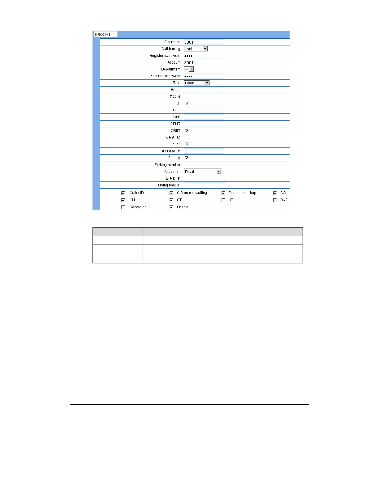
Click
to open the whole configuration interface of IP extension.
Page 34
Shanghai New Rock Technologies Inc. Page34/75
Figure 2-9 Others configuration interface of IP extension
Table 2-9 Others parameter of IP extension
Name Description
Same as analog extension.
Using fixed IP
If the SIP terminal uses IP address as the means of security verification,
enter the static IP address of the terminal.
2.4.3 Department
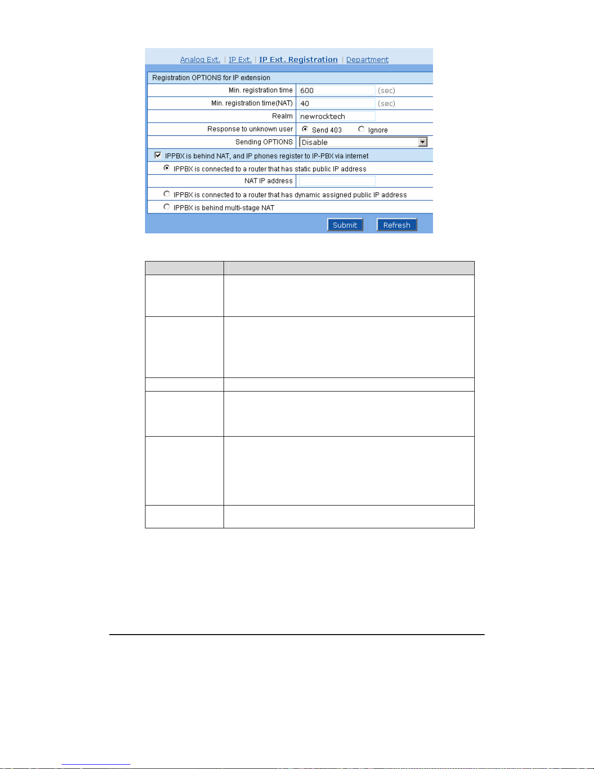
After login, click “Extension > IP Ext. Registration” tab to open the configuration interface.
Page 35
Shanghai New Rock Technologies Inc. Page35/75
Figure 2-10 Registration configuration interface of IP extension
Table 2-10 Registration configuration parameter of IP extension
Name Description
Min. Registration
Time
When IP extension is not behind NAT, the minimum registration time
cannot be smaller than this value. If the registration time of IP extension
is smaller than this value, the OM will tell IP extension terminal about
the restriction with a 423 message.
Min. Registration
Time of IP
Extension Behind
NAT
When IP extension is behind NAT, the minimum registration time
cannot be smaller than this value. If the registration time of IP extension
is smaller than this value, the OM will tell IP extension terminal about
the restriction with a 423 message. Normally, when IP extension is
behind NAT, the OM should allow the extension for a new registration in
a shorter time to ensure reliable connection.
Realm Used for IP extension authentication.
Response to
Unknown User
Processing modes for SIP terminal without an account attempting to
register to the OM:
Send 403: Send 403 to the IP extension in response;
Ignore: Make no response to registration.
Sending OPTIONS
The OM maintains the session status by sending OPTIONS regularly.
The following selections can be made according to application scenarios:
z Disable
z To registered IP Ext. behind NAT
z To any registered IP Ext.
Time interval for
OPTIONS
30~65535 s.
Page 36

Shanghai New Rock Technologies Inc. Page36/75
Name Description
IPPBX is behind
NAT, and IP phones
register to IP-PBX
via internet
z IPPBX is connected to a router that has static public IP address. Set
the public IP address of router.
In this case, the public IP address that the router maps to the OM is
static, so external IP extensions can register to the OM through this
public address. But since the OM is behind the router (NAT), it is
required to enable port mapping for signaling and voice port of the OM
on the router to ensure normal communication by IP extension.
z IPPBX is connected to a router that has dynamic assigned public IP
address. Set if DDNS service supplied with the OM is used: fill in the
user name, password and domain name if Yes is selected; fill in the
DDNS domain name if No is selected.
When enterprises are connected to the Internet through ADSL, the public
IP addresses that operators provide are usually dynamic, namely, the
public IP addresses that the router maps to the OM are always changing.
So external IP extensions cannot register to the OM through a static
address. To solve this problem, users are required to assign a domain
name for the OM by applying for DDNS service, then external IP
extensions can register to the OM through this domain name. Also, since
the OM is behind the router (NAT), it is required to enable port mapping
for signaling and voice port of the OM on the router.
z IPPBX is behind multi-stage NAT (e.g. There exists a multi-stage
router between the IPPBX and the Internet).
In this case, since there exists a multi-stage router between the OM and
the Internet, and the router controlled by an enterprise is behind NAT,
the communication problem between the OM and external IP extensions
cannot be solved simply by port mapping. Therefore, it is needed to
enable STUN function (STUN protocol provides a way by which it can
get the address and port mapped by NAT, and so replace the private
network address and port in application layer to traverse NAT) for
working with the STUN server in public network to access the OM
behind NAT, ensuring normal communication by external IP extensions.
The OM has three strategies for using STUN service:
1、 Startup: The OM sends STUN request for signaling port to the
STUN server only at application boot;
2、 Periodic: The OM sends STUN request for signaling port to the
STUN server on a periodical basis;
3、 Periodic & RTP: The OM sends STUN request for signaling and
voice ports to the STUN server on a periodical basis.
In this case, it is still needed to fill in DDNS or static NAT address for IP
extension registering to the OM.
2.4.4 Department
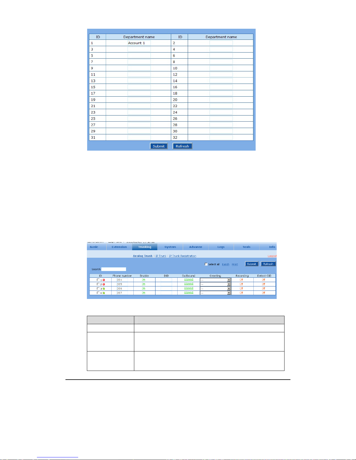
After login, click “Extension > Department” tab to open the configuration interface.
Page 37
Shanghai New Rock Technologies Inc. Page37/75
Figure 2-11 Department configuration interface
Department setting interface is mainly used for setting department (group) name, with which is filled
in the blanks. Intra-department pickup and assistant functions will use the department information.
After the department is set, it will appear on the dropdown list under “Department” on the “Extension
> Analog Ext.” and “Extension > IP Ext.” configuration interface for extension management and
assistant.
2.5
Trunking
2.5.1 Analog Trunk
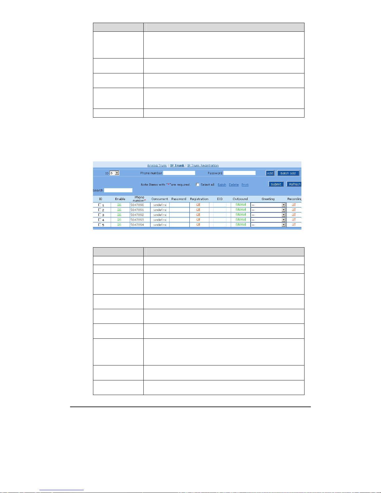
After login, click “Trunking > Analog Trunk” tab to open the configuration interface.
Figure 2-12 Configuration interface of analog trunk
Table 2-11 Configuration parameter of analog trunk
Name Description
ID Analog trunk ID, which is automatically created by the system.
Phone Number
Assign a phone number for this trunk line. When there is no caller ID
display, the system will use this number as the caller ID. This number is
also used in the Call Detail Record (CDR).
Enable
Enable this analog line. If FXO port fails or other maintenance happens,
it is suggested to disable this line to ensure it will not be selected when
making outgoing calls.
Page 38
Shanghai New Rock Technologies Inc. Page38/75
Name Description
DID
Set an extension number bound with this analog trunk. Enter the
extension number to enable DID function. When there is an incoming
call on this line, the system will ring the corresponding extension
directly.
Outbound
Select if Outbound is activated. This line can only be used for incoming
calls when this function is activated.
Greeting
Set the operator greeting for this analog trunk. The default greeting is
used when the status is off.
Recording
Select if Recording is activated. The OM will record calls (including
incoming and outgoing calls) on this analog trunk when this function is
activated.
Detect CID Select if Caller ID detection is activated.
2.5.2 IP Trunk
After login, click “Trunking > IP Trunk” tab to open the configuration interface.
Figure 2-13 General configuration interface of IP trunk
Table 2-12 General configuration parameter of IP trunk
Name Description
ID IP Trunk ID, which is automatically identified by the system.
Enable Enable this IP line.
Phone number
Assign a phone number for this trunk line. When there is no caller ID
display, the system will use this number as the caller ID. This number is
also used in the Call Detail Record (CDR).
Concurrent
Set the maximum concurrent calls allowed on the trunk. The default is
1.The number must be no bigger than the total number SIP trunks.
Password
Configure an authentication password for the registration account.
Obtain it for the operator or system administrator.
Registration
Select if this account is registered with the operator. By default, this is
off.
DID
Set an extension number bound with this analog trunk. Enter the
extension number to enable DID function. When there is an incoming
call on this line, the system will ring the corresponding extension
directly.
Outbound
Select if Outbound is activated. This line can only be used for incoming
calls when this function is activated.
Greeting
Set the operator greeting for this analog trunk. The default greeting is
used when the status is off.
Page 39
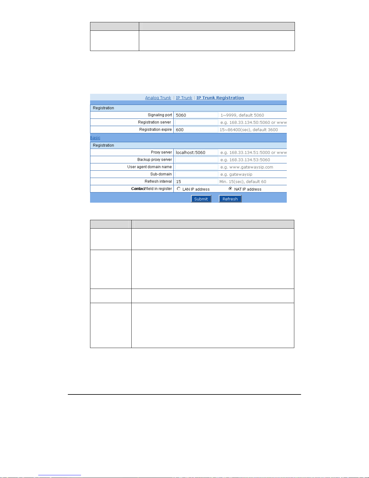
Shanghai New Rock Technologies Inc. Page39/75
Name Description
Recording
Select if Recording is activated. The OM will record calls (including
incoming and outgoing calls) on this analog trunk when this function is
activated.
2.5.3 IP Trunk Registration
After login, click “Trunking > IP Trunk Registration” tab to open the configuration interface.
Figure 2-14 Registration configuration interface of IP trunk
Table 2-13 Registration configuration parameter of IP trunk
Name Description
Signaling Port Configure the SIP port, with its default value 5060.
Note: The signaling port number can be set in the range of 1-9999, but
cannot conflict with the other UDP port numbers used by the equipment.
Registration
Server
Configure the address and port number of SIP registration server, and the
address and port number are separated by “:”. It has no default value.
The registration server address can be an IP address or a domain name.
When a domain name is used, it is required to activate DNS service and
configure DNS server parameters on the page of configuring network
parameters. For example: “201.30.170.38:5060”, “register.com:5060”.
Registration
expire
Valid time of SIP re-registration in second.
Proxy Server
Configure the IP address and port number of SIP proxy server, and the
address and port number are separated by “:”. It has no default value.
The proxy server address can be set to an IP address or a domain name.
When a domain name is used, it is required to activate DNS service and
configure DNS server parameters on the page of configuring network
parameters. Examples of complete and effective configuration:
“201.30.170.38:5060”, “softswitch.com:5060”.
Page 40
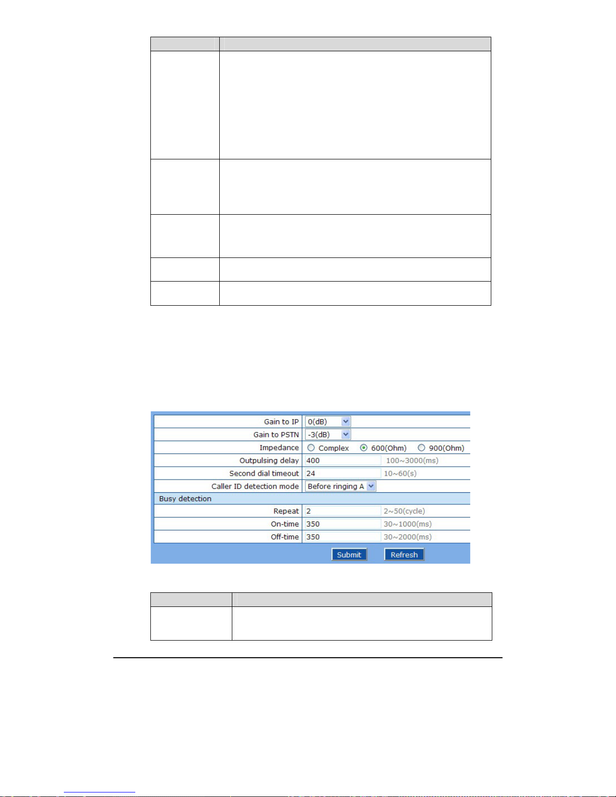
Shanghai New Rock Technologies Inc. Page40/75
Name Description
Backup Server
Configure the IP address and port number of backup proxy server. It has no
default value. Add the address of calling proxy server here, and the OM can
support selection function of multiple softswitch addresses through IP
address. The format must IP address format and complete and effective
configuration, eg. “202.202.2.202:2727”. The proxy and registration servers
must be identical.
Conditions for falling over to the backup proxy server (any):
1)The OM registration is timeout;
2)No response to master server calls is timeout.
User Agent
Domain Name
This domain name will used in INVITE messages. If it is not set here, the
OM will use the IP address or domain name of IMS core network portal as
user agent domain name. It has no default value.
It is not recommended to use LAN IP address to set domain name
parameter.
Sub-domain
Used for registered domain name, it is needed to configure only when the
domain name used for registration and the user agent domain name are
inconsistent. If it is null, the user agent domain name will be used for
registration.
Refresh Interval
Interval of sending null UDP packet to SIP registration server, sent null
UDP packet is used to ensure constant NAT port.
Contact field in
register
Address behind NAT used in the Contact header field of SIP messages sent.
2.6
System
2.6.1 Characteristics of trunk line
After login, click the label of “System > trunk” to open this interface.
Figure 2-15 Trunk line characteristics configuraiton interface
Table 2-14 Configuration parameter of trunk line characteristics
Name Description
Gain to IP
Set the voice volume gain towarding IP side, the default is 0. Taking
decibel as the unit, setting range is -3 ~ +9 decibe ls. -3 means declining
of 3 decibels; +3 denotes the amplification of 3 decibels.
Page 41
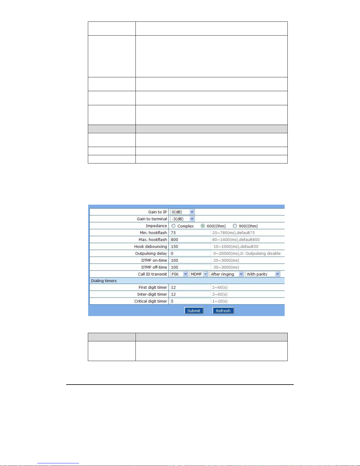
Shanghai New Rock Technologies Inc. Page41/75
Gain to PSTN
Set the voice volume gain towarding PSTN side, the default is -3. Taking
decibel as the unit, setting range is -6 ~ +9 decibels.
Impedance
Set the parameter of FXO line impedance, with the default of 600 ohm.
The optional settings as below:
z Complex
z 600(ohm)
z 900(ohm)
Outplusing delay
The time interval between FXO going off-hook and starting outpulsing
the first digit to PSTN. The default is 400 in milliseconds.
Inbound first digit
timeout
Set the timeout of calling DTMF on FXO port for inbound calls, ranging
from 10-60 seconds, with default of 24 seconds.
Caller ID detection
mode.
Select according to the characteristics of field lines. Before ringing A,
after ringing A, before ringing B, after ringing B. Note: A and B here
refer to two detection means provided within the equipment.
Busy Detection
Repeat
OMs will regard the busy tone signal with the repeat times specified here
as a valid hang-up signal. Default is 2, effective range is 2 ~ 50.
On-time Set duration of busy tone signal, the default is 350 in milliseconds.
Off-time Set the interval time of busy tone, the default is 350 in milliseconds.
2.6.2 Characteristics of line
After login, click the label of “System> line” to open this interface.
Figure 2-16 Line characteristics configuration interface
Table 2-15 Line characteristics configuration parameter
Title Explanation
Gain to IP
Set the voice volume gain towarding IP side, the default is 0. Taking
decibel as the unit, setting range is -3 ~ +3 decibe ls. -3 means declining
of 3 decibels; +3 denotes the amplification of 3 decibels.
Page 42

Shanghai New Rock Technologies Inc. Page42/75
Title Explanation
Gain to terminal
Set the voice volume gain towarding FXS port side, the default is -3.
Taking decibel as the unit, setting range is -6 ~ +3 decibels. -3 means
declining of 3 decibels; +3 denotes the amplification of 3 decibels.
Impedance
Select the parameter of FXS port line impedance, and the default value is
600 ohm. The optional values as below:
z Complex
z 600(ohm)
z 900(ohm)
Min.hookflash
Used to detect Hook Flash event, the default is 75 milliseconds. Any
flash that fall short of the shortest flash time will be ignored. Generally,
this value should not be less than 75 milliseconds.
Max. hookflash Used to detect hook flash, the default is 800 milliseconds.
The OM will regard the flash duration between “Min. hookflash” and
“Max.hookflash” as an effective flash. Any flash lasting over the longest
time will be considered as a valid hang up. Generally, this value should
not be less than 800 milliseconds.
Hook debouncing
Used to avoid the glitch of the phone status, with default of 50
milliseconds.
When the duration from hang-up to off-hook falls short of this value, the OM will
ignore the status variation, and consider the phone remains hang-up status. In case
of vice versa, the OM will ignore the status variation, and consider the phone
remains off hook status. Effective range of setting is 10~1000 milliseconds.
Outpulsing delay
Used when OMs’ FXS port is connected with the trunk interface of
PBXs. For calls from OM to PBX, OMs will relay the extensions to PBX
after the delay set here. Setting of “0” means no extension number relay.
The default is 0 millisecond.
DTMF on-time
This parameter sets the on time (in ms) of DTMF signal sent from FXS
port. The default value is 100 ms. Generally, the duration time should be
set in the range of 80 ~ 150 ms.
DTMF off-time
This parameter sets the off time (ms) of DTMF signal sent from FXS
port. The default value is 100 ms. Generally, the interval time should be
set in the range of 80 ~ 150 ms.
Call ID transmit
Select transmission mode of Caller ID signal from the FXS port to the
phone.
z FSK or DTMF;
z SDMF or MDMF;
z Sending Caller ID data before or after ringing;
z Sending Caller ID data with or without parity.
Dialing Timers
First digit timer
If a user hasn’t dialed any number within a specified time by this
parameter after offhook, the OMs will consider that the user has given
up the call and prompt to hang up in busy tone. Unit: second, default
value: 12 seconds.
Inter-digit timer
If a user hasn’t dialed the next number key from the time of dialing the
last number key to the set time by this parameter, the OMs will consider
that the user has ended dial-up and call out the dialed number. The
default value is 12 seconds, unit: second.
Page 43
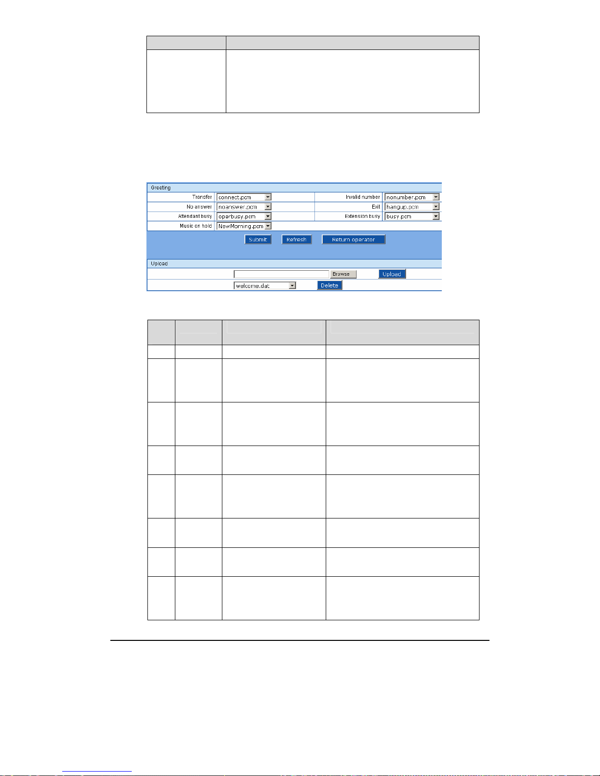
Shanghai New Rock Technologies Inc. Page43/75
Title Explanation
Critical digit timer
This parameter is used with the "x.T" rule set in dialing rules. For
example, there is "021.T" in the dialing rules table. When a user has
dialed 021 and hasn’t dialed the next number within a set time by this
parameter (eg. 5 seconds), the OMs will consider that the user has ended
dial-up and call out the dialed number 021.
The default value is 5 seconds, unit: second.
2.6.3 Greeting
After login, click “System > Greeting” tab to open the configuration interface.
Figure 2-17 Configuration interface of greeting
Table 2-16 Voice File Table Used on the OM
No
(NN)
File Name Prompt Usage Prompt Content
00 Recording in buffer
01 welcome
Greeting for working
hours*
Thank you for calling. If you know your
party's extension, please dial it now. Or, to
transfer to an operator, press 0
02 offhour
Greeting for off hours Thank you for calling. The office is
closed. If you know the extension, please
dial it now
03 operator
Transfer to operator Please wait, while your call is transferred
to an operator
04 operbusy
Operator in busy Sorry, the call can not be answered at this
time, please dial other numbers. Or, dial 0
for an operator
05 nonumber
Vacant or invalid number Sorry, the number you dialed is not valid.
Please check the number and dial it again
06 noanswer
No answer Sorry, the call can not be answered at this
time, please dial other numbers
07 busy
Busy line Sorry, the line is busy at this time, plea se
dial other numbers, or dial 0 for an
operator
Page 44
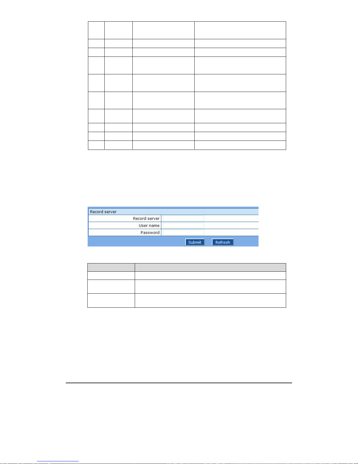
Shanghai New Rock Technologies Inc. Page44/75
08 tryagain
Resource congestion Sorry, your call can't be completed at this
time, please hang up and try later
09 connect
Call transfer Please wait, while your call is transferred
10 vm_all
Reminder for voice mail Please leave a message after the tone
11 vm_busy
Reminder for voice mail The extension is busy now, please leave a
message after the tone
12 vm_noans
Reminder for voice mail There is no one to answer the call, please
leave a message after the tone
13 hangup
Disconnect a call Sorry, your call will be disconnected.
Thank you for calling
15
NewMorni
ng
Background or CRBT
fring1 Background or CRBT
fring2 Background or CRBT
record Reminder for recording Start record after the tone
*: System default
2.6.4 Recording
After login, click “System > Recording” tab to open the configuration interface.
Figure 2-18 Configuration interface of recording
Table 2-17 Configuration parameter of recording
Name Description
Address Set the IP address and port number of recording storage server.
User Name
Set the ftp user name for logging on to the recording server. It is used for
the assistant to download call record and voice mail, etc.
Password
Set the ftp password for logging on to the recording server. It is used for
the assistant to download call record and voice mail, etc.
Page 45
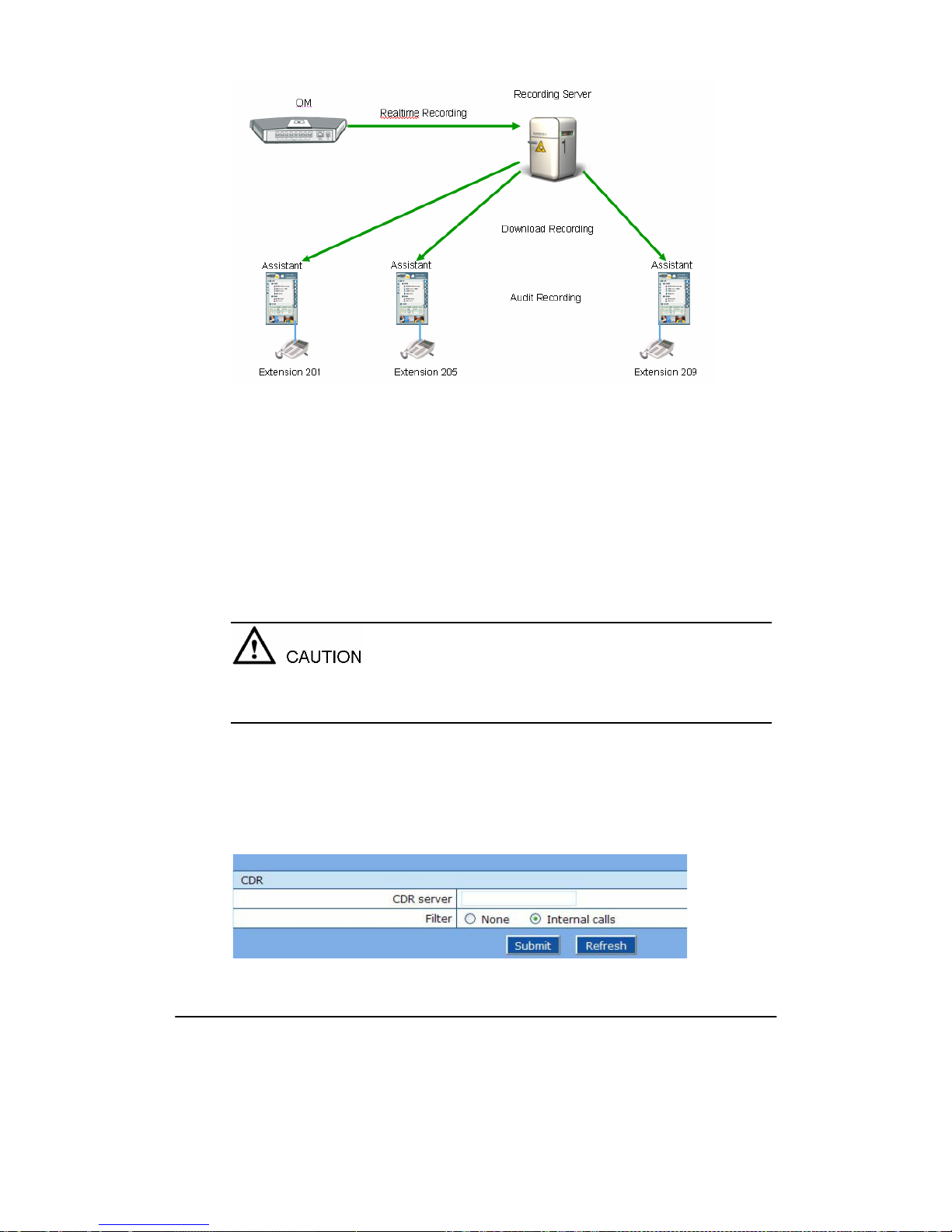
Shanghai New Rock Technologies Inc. Page45/75
Figure 2-19 Framework of Recording
The in-built call recording function of OM can provide reliable and safe phone call recording for
corporate users. The recording function consists of OM’s in-built recording software module,
external audio processing software and recording storage server, and the OM is connected to the
recording storage server via LAN.
In-built recording software module: Send voices of the two parties to the recording storage server in
the form of IP packet in batch;
Audio processing software: It (omrecord.exe) is an application software running on Windows XP in
the background. Its main functions include receiving recording packets sent by the OM, enabling
code conversion (convert G.711 or G.729 into MP3) and storing the recording in a time-dependent
way.
Recording storage server: Windows XP system, used for recording packet processing and storage.
The recording software is only used to store call recording in MP3, by time and number. System
administrator is responsible for the management of recorded files.
The recording can be played back with any MP3 player, such as Windows Media Player.
For more details about recording, see Appendix 3.2.
2.6.5 Call Record
After login, click “System > Call Record” tab to open the configuration interface.
Figure 2-20 Configuration interface of call record
Page 46
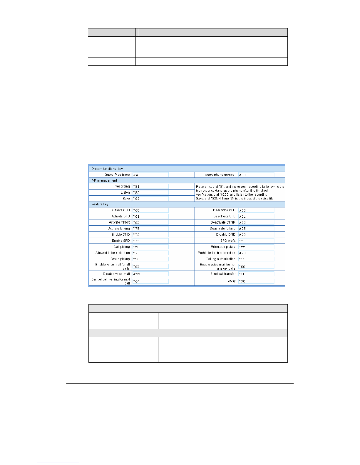
Shanghai New Rock Technologies Inc. Page46/75
Table 2-18 Configuration parameter of call record
Name Description
CDR Server Set the IP address and port number of server for storing call records.
Note: If port number is not configured, the default port number 1809 will
be used.
Filter Select what calls are not recorded: None or Internal calls.
2.6.6 Functional keys
The function key consists of system function key and service function key. The system function key
is used for acquiring OM information, and the later is used for users to activate, inactivate extension
features.
After login, click the label of “System> Functional Keys” to open this interface.
The following are the examples of the dialing rule for the function key:
a) Using *xx (dial * and 2 digits number ) to activate a service;
b) Using #xx (dial # and 2 digits number) to cancel a service.
Illustrate with following defaults of various parameters, which may be modified according to
requirements.
Figure 2-21 Functional keys configuration interface
Table 2-19 The use of feature codes
System Codes
Inquiry of IP address Pick up the phone on any extension + ##
Inquiry of extension number Pick up the phone of the extension + #00
Making Recording of Voice files
Start recording
Pick up the phone of any extension + *81 + hang up after
recording
Replay
Pick up the phone + *82
Page 47

Shanghai New Rock Technologies Inc. Page47/75
Save
Pick up the phone + *83NN
Note: NN is the index of the voice files (see Appendix 4 for
the list of all voice files)
Feature Codes
Activate call forwarding
variable (CFU)
Forwarding calls to an extension:
Pick up the phone + *60 + the extension number of the third
party
Forwarding calls to an external number::
Pick up the phone + *60 + the prefix of selecting trunk + *the
number of the new destination
Verify the destination number
of CFU
Pick up the phone + *60*
Deactivate CFU
Pick up the phone + #60
Activate call forwarding on
busy (CFB)
Forwarding calls to an extension:
Pick up the phone + *61 + the extension number of the
third party
Forwarding calls to external number:
Pick up the phone + *61 + the prefix of the selecting trunk +
*the number of the new destination
Verify the destination number
of CFB
Pick up the phone + *61*
Deactivate CFB
Pick up the phone + #61
Activate call forwarding on no
answer (CFNR)
Forwarding calls to an extension:
Pick up the phone + *62 + the extension of the third party
Forwarding calls to an external number:
Pick up the phone + *62 + prefix of selecting trunk + *the
external number of the third party
Verify the destination number
of CFNR
Pick up the phone + *62*
Deactivate CFNR Pick up the phone + #62
Activate call splitting Forking calls to an extension:
Pick up the phone+ *75 + the external number
Forking calls to an external number:
Pick up the phone + *75 + prefix of selecting trunk + *the
external number
Verify the phone number of the
second terminal
Pick up the phone + *75*
Deactivate the call splitting Pick up the phone + #75
Activate do not disturb (DND) Pick up the phone + *72
Deactivate DND Pick up the phone+ #72
Program the speed dial (SD)
list
Pick up the phone+ *74 + MM + the original number
Note: MM is in the range of 20~49
Listen to the SD list
Pick up the phone + *74 + MM + *
Page 48

Shanghai New Rock Technologies Inc. Page48/75
Delete SD list
Pick up the phone + *74 + MM
Dial SD
Pick up the phone + ** + MM
Pick up the call to an operator
Pick up the phone + *50
Pick up the call to an extension
Pick up the phone + *55 + the extension number
Allowed calls on the extension
being picked up
Pick up the phone + *73
Inhibiting calls on the
extension being picked up
Pick up the phone + #73
Group pickup Pick up the phone + *56.
Calling authorization
Pick up the phone + *33 + the extension number +
authorization code + the called party number
Note: there should be no outbound calling restriction on this
extension
Enable voice mail for all calls Pick up the phone + *65.
Enable voice mail for
no-answer calls
Pick up the phone + *66.
Disable voice mail Pick up the phone + #65.
Listen to the color ring back
tone (CRBT)
Pick up the phone + *88 + the two-digit index of the ring file
Enable CRBT Pick up the phone + *80 + the two-digit index of the ring file
Deactivate CRBT Pick up the phone + #80
Three-way calling
During the two-way conversation, hook-flash + *79 + the
third party’s number + hook-flash again after in talk with the
third party
Disable call waiting for the
next call
Pick up the phone+ *64
Blinded call transfer
During conversation with the first party, hook-flash + *38 +
the extension number of the second party + hang up
Attended call transfer
D During conversation with the first party, hook-flash + the
extension number + hang up
2.6.7 Tones
After login, click “System > Tones” tab to open the configuration interface.
Page 49
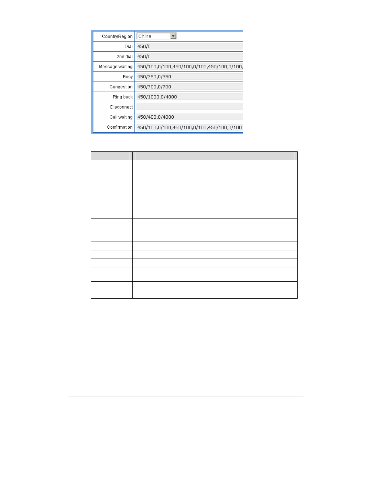
Shanghai New Rock Technologies Inc. Page49/75
Figure 2-22 Configuration interface of tones
Table 2-20 Configuration parameter of tones
Name Description
Country/region
There are progress tone plans for several countries and regions which are
pre-programmed in gateways. Users may also specify the tone plan
according to the national standard. Gateways provide tone plan for the
following countries and regions:
China; the United States; France; Italy; Germany; Mexico; Chile; Russia;
Japan; Korea; Hong Kong; Taiwan; India; Sudan; Iran; Algeria; Pakistan;
Philippines; Kazakhstan.
Dial Prompt tone of off-hook dialup
2nd dial Used for the second stage dialup
Message waiting
Used for prompt of voice mail, or when the subscriber line is set with “Don’t
Disturb Service and Call Transfer”.
Busy Used for busy line prompt
Congestion Used for notification of call set up failure due to resource limit
Ring back The prompt tone sent to caller when ring
Disconnect
Used for reminding the subscriber of off-hook and no dialup status of the
phone
Call waiting Used for notification in call waiting
Confirmation Used for confirming function keys being entered.
2.7
Advanced Configuration
2.7.1 System
After login, click the label of “Advanced > System” to open this interface.
Page 50
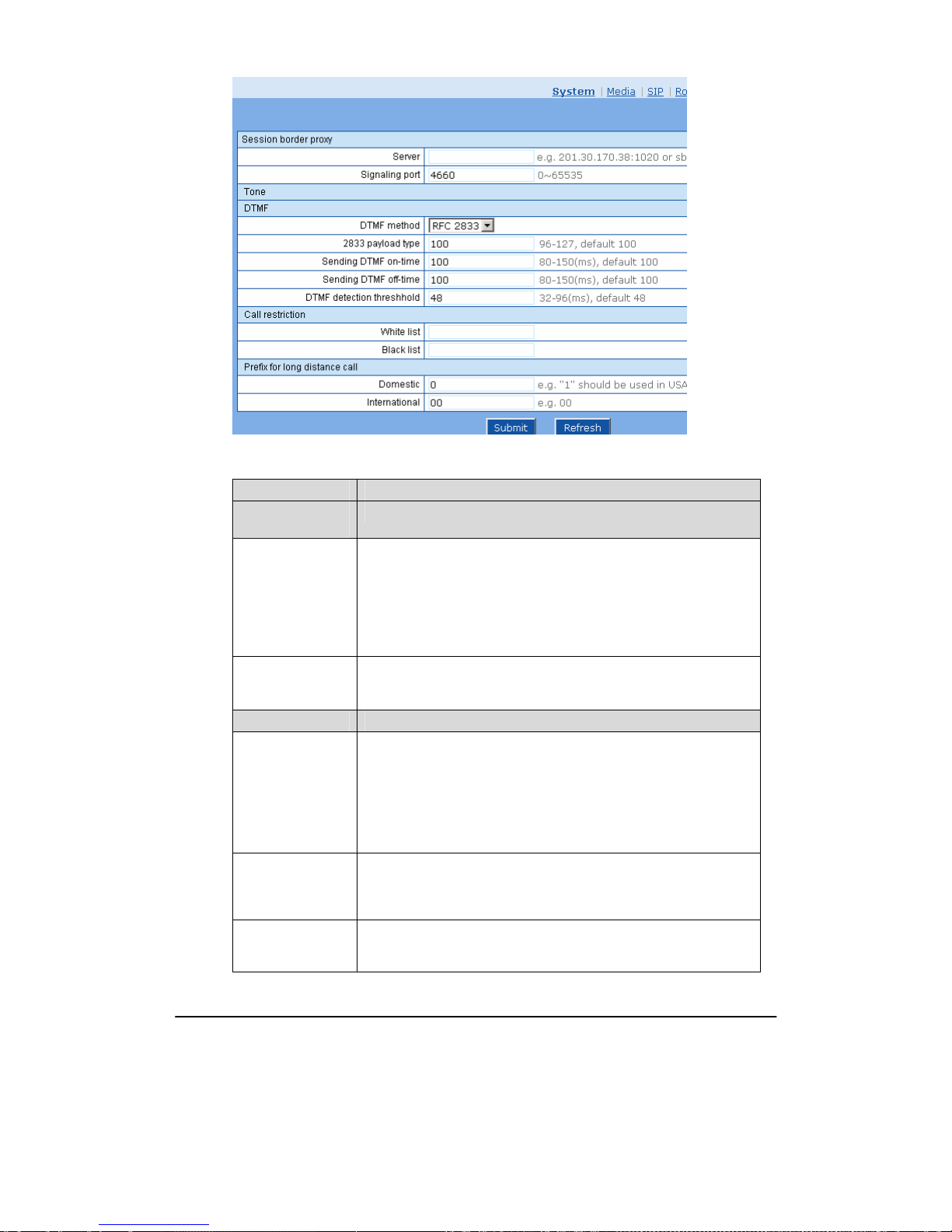
Shanghai New Rock Technologies Inc. Page50/75
Figure 2-23 Inferface of system advanced configuraiton
Table 2-21 Parameters of system advanced configuration
Title Explanation
Session border
proxy
Server
Set the IP address and port number of session border proxy server. The
character of “:” must be used between IP address and port number.
Server address could be set into IP address or domain name. When
domain name is used, “DNS service” must be activated as shown in the
page of “Configure network parameter”, and “DNS server” must be
configured.
Examples: “201.30.170.38:5060” and “softswitch.com:5060”.
Signaling port
Signaling port value of the OM,the default value is 4660. Signaling port
number could be set at will, but can not conflict with other ports of
equipment.
DTMF
DTMF method
Transmission modes of DTMF signal supported by the OMs include
Audio, RFC 2833 and SIP INFO. The default value is Audio.
Audio: DTMF signal is transmitted to the platform with sessions;
SIP INFO: Separate DTMF signal from sessions and transmit it to the
platform in the form of SIP INFO messages;
RFC 2833: Separate DTMF signal from sessions and transmit it to the
platform through RTP data package in the format of RFC2833.
2833 payload type
Used with “RFC 2833” in the DTMF transmission modes. The default
value of 2833 payload type is 100. The effective range available: 96 ~
127. This parameter should match the setting of far-end device (e.g.
platform).
Sending DTMF
on-time
This parameter sets the on time (in ms) of DTMF signal sent from FXO
port. The default value is 100 ms. Generally, the duration time should be
set in the range of 80 ~ 150 ms.
Page 51

Shanghai New Rock Technologies Inc. Page51/75
Title Explanation
Sending DTMF
off-time
This parameter sets the off time (ms) of DTMF signal sent from FXO
port. The default value is 100 ms. Generally, the interval time should be
set in the range of 80 ~ 150 ms.
DTMF detection
threshold
Minimum duration time of effective DTMF signal. Its effective range is
32-96 ms and the default value is 48 ms. The greater the value is set, the
more stringent the detection is.
Call restriction
White list
This parameter is used for setting a trunk number or prefix always
allowed to call, such as emergency number (110), and even extensions
without permission to call a trunk can call this number (number range). It
is generally used to set emergency numbers such as 110|119|120.
Black list
This parameter is used for setting a trunk number or prefix prohibited to
call, such as charge number range (900), and even extensions with
permission to make international calls cannot call this number range. It is
generally used to set numbers prohibited to call in any case. Examples:
900|17909.
Prefix for long
distance call
Domestic
This parameter is used for setting a trunk number or prefix prohibited to
call domestically, and even extensions with permission to make domestic
calls cannot call this number range. The default value is 00, indicating
numbers starting with 00 are prohibited to call.
International
This parameter is used for setting a trunk number or prefix prohibited to
call internationally, and even extensions with permission to make
international calls cannot call this number range. The default value is null
but can be set to codes of some countries, indicating numbers in these
countries are prohibited to call.
2.7.2 Media
After login, click the label of “Advanced >Media” to open this interface.
Page 52
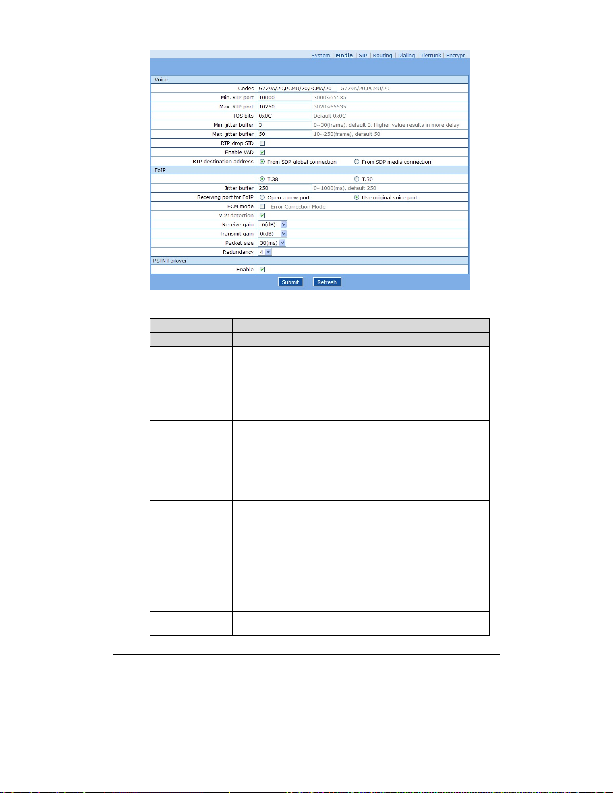
Shanghai New Rock Technologies Inc. Page52/75
Figure 2-24 Configuration interface of media
Table 2-22 Configuration parameter of media
Name Description
Voice
Codec
Codec supported by the OM include G729A/20, PCMU/20, PCMA/20
(as shown in Table 2-23). This parameter must be set due to no default
value.
Several encoding methods can configure in this item at the same time,
separated with “,” in the middle; the OM will negotiate with the
platform in the order from front to back when configuring the codec
methods
Min. RTP port
The minimum value of UDP ports for RTP transmission and receiving,
and the parameter must be greater than or equal to 3000. This field must
be filled in.
Max. RTP port
The maximum values of UDP ports for RTP’s transmission and
receiving.
This field must be filled in. It’s advisable to be greater than or equal to
“2× number of lines +min. RPT port”.
iLBC payload type
Set the RTP payload type of iLBC,and the default value is 97. Accepted
value is 97 ~ 127. The parameter shall be configured in conformity to
that of platform.
TOS bits
This parameter specifies the quality assurance of services with different
priorities. The factory setting is 0x0C. For the mapping between the
levels that has no reliability requirement and the TOS value, see Table
2-24.
Min. Jitter buffer
RTP Jitter Buffer is constructed to reduce the influence brought by
network jitter. This default value is 3. Higher value of this parameter
could result in longer delay; therefore, it should be set with caution.
Max. Jitter buffer
RTP Jitter Buffer helps to reduce the influence brought by network
jitter. The default value is 50.
Page 53

Shanghai New Rock Technologies Inc. Page53/75
Name Description
RTP drop SID
Determine whether to discard received RTP SID voice packets. By
default, SID voice packets will not be dropped.
Note: RTP SID packets should be dropped only when they are in
unconformity to the specifications. Nonstandard RTP SID data could
generate noise for calls.
RTP destination
address
The default value is from SDP media connection.
z From SDP global connection: Obtain the peer IP address from SDP
global connection;
z From SDP media connection: Obtain the peer IP address from
Connection Information behind SDP Media Description.
FoIP
Select fax mode: T.38 or T.30
Jitter buffer
Set the extent of T.38 jitter buffer, and the default is 250. The valid
range is 40 ~ 1000 in milliseconds.
Receiving port for
FoIP
Set whether to open a new port when the OM is switching to T.38 mode,
and by default, original voice port will be used.
z Open a new port: Use the new RTP port;
z Use original voice port: Use the original RTP port that created on call
set.
ECM
Determine whether to use corrective mode of fax. By default, it is not
selected.
V21 Signal detection
Select if V21 signal detection is used when T.38 faxes. The default
value is “Not Select”.
Receive gain Set the receiving gain of T.38 fax, with the default of -6dB.
Transmit gain Set the transmission gain of T.38 fax, with the default of 0dB.
Packet size Set the packet size of T.38. 30 milliseconds is the default value.
Redundancy
Set the number of the redundant frames in T.38 data package, default is
4.
PSTN failover
Network fault routed
to analog trunk
In the case of network fault, outgoing calls are automatically routed to
FXO port. The default value is “Select”.
Table 2-23 Codec Methods Supported by OM
Codec Supported by OM
Bit Rate (Kbit/s)
Time Intervals of RTP Package
Sending (ms)
G729A 8 10/20/30/40
PCMU/PCMA 64 10/20/30/40
Table 2-24 Mapping between the reliability requirement and the TOS value
Level
TOS Value (High Delay
and High Throughput)
TOS Value (Low Delay
and Low Throughput)
TOS Value (Low Delay
and High Throughput)
0
0x08 0x10 0x18
1
0x28 0x30 0x38
2
0x48 0x50 0x58
3
0x68 0x70 0x78
Page 54
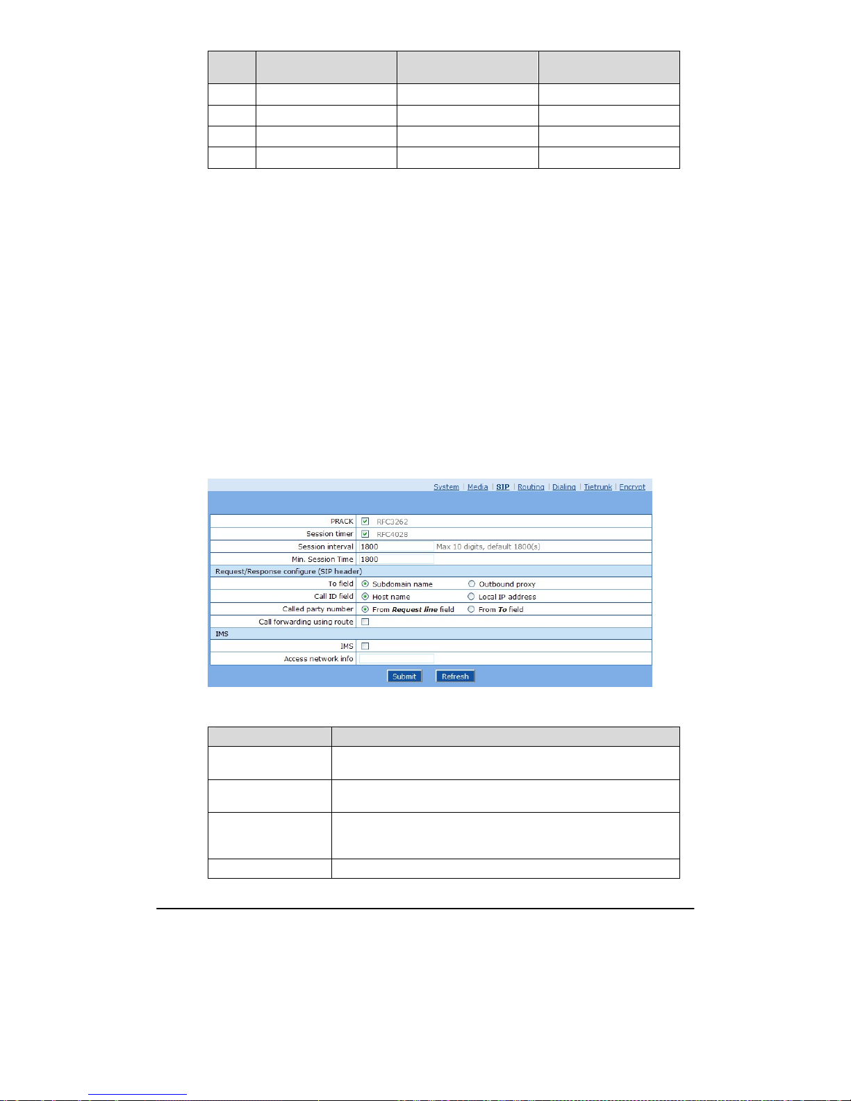
Shanghai New Rock Technologies Inc. Page54/75
Level
TOS Value (High Delay
and High Throughput)
TOS Value (Low Delay
and Low Throughput)
TOS Value (Low Delay
and High Throughput)
4
0x88 0x90 0x98
5
0xA8 0xB0 0xB8
6
0xC8 0xD0 0xD8
7
0xE8 0xF0 0xF8
2.7.3 SIP related configuration
The SIP messages consist of request message and response message. Both include SIP message
header field and SIP message body field. SIP message header mainly describes the message sender
and receiver; SIP message body mainly describes the specific implementation method of the dialog.
Message of request: the SIP message sent by a client to the server, for the purpose of activating the
given operation, including INVITE, ACK, BYE, CANCEL, OPTION and UPDATE etc.
Message of response: the SIP message sent by a server to the client as response to the request,
including 1xx, 2xx, 3xx, 4xx, 5xx, and 6xx responses.
Message header: Call-id.
Parameter line: Via, From, To, Contact, Csq, Content-length, Max-forward, Content-type, White
Space, and SDP etc.
OMs provide good flexibility in content setting in order to improve the compatibility with the
platform.
After login, click the label of “Advanced > SIP” to open this interface.
Figure 2-25 SIP related configuration interface
Table 2-25 Configuration parameter of SIP related
Name Description
PRACK
Determine whether to activate Reliable Provisional Responses. (RFC
3262)
Session timer
Choose to activate session refresh (Session Timer, RFC 4028). By
default, session timer is not activated.
Session interval
Set the session refresh interval. The value of Session-Expires is
enclosed into INVITE or UPDATE messages. Default value is 1800 in
second.
Minimum timer Se t the minimum value of session refresh interval.
Page 55
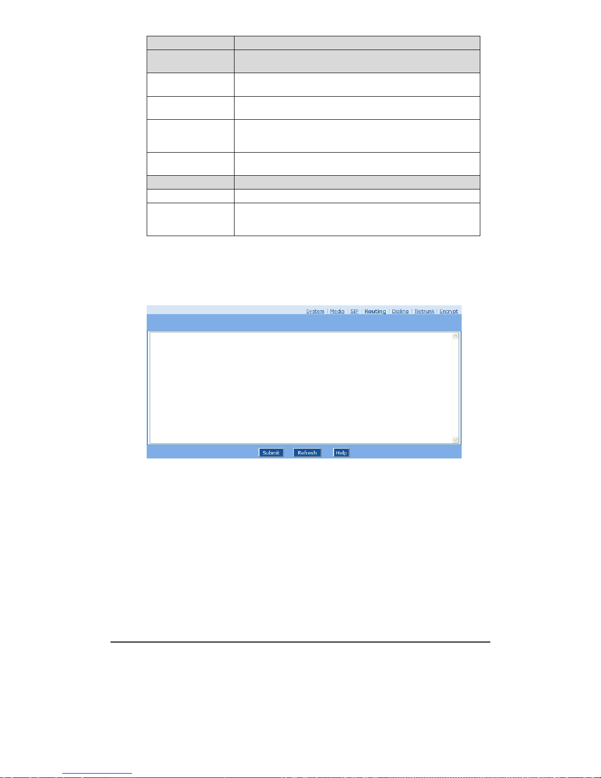
Shanghai New Rock Technologies Inc. Page55/75
Name Description
Request/Response
Configure
To field
Choose whether to apply Domain name or Outbound proxy to “To”
header field, the default is “Domain name”.
Address in Call ID
field
Choose whether to fill Call ID field with host name or local IP, the
default is “local IP address”.
Called party number
Choose whether the OM acquires the called number from Request
Line header field or To header field. The default is “from Request
Line”.
302 Contact with
switched prefix
If activated: When sending 302 call forwarding, transferred number is
required to switch over the routed number, or it will be used directly.
IMS
IMS Activate SIP function compatible with 3GPP IMS standard.
Access network
information
Set the header field value of P-Access-network-info. The OM will
include the header field of P-Access-network-info in SUBSCRIBE
and INVITE message.
2.7.4 Routing Table
After login, click “Advanced > Routing Table” tab to open the configuration interface.
Figure 2-26 Configuration Interface for Routing Table
Click “Help” to open the illustrative interface for routing configuration.
Page 56
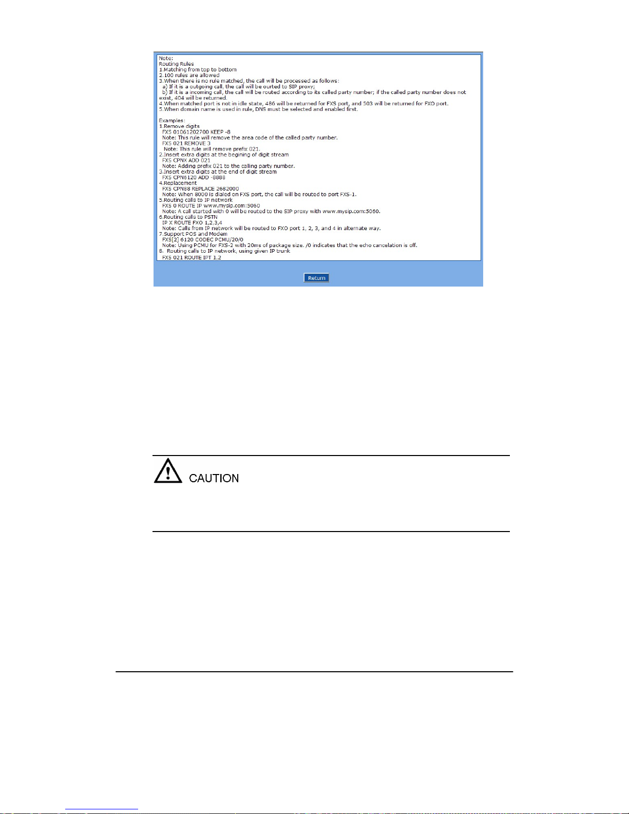
Shanghai New Rock Technologies Inc. Page56/75
Figure 2-27 Illustrative interface for routing configuration
The routing table with 50 rules in capacity provides two functions including digit transformation and
call routing assignment. Here are the general rules applied by OMs when executing the routing table:
1. The routing rules in the table are executed from top to down, and the number matching follows
the principle of minimum & priority matching;
2. When there is no rule matched, the call will be processed as follows:
a) For outbound calls, calls will be routed to SIP proxy;
b) For inbound calls, calls will be routed according to its called party number, and if the
called party number does not exist, 404 will be returned.
3. When matched port is not in idle state, 486 will be returned for FXS port, and 503 will be
returned for FXO port.
4. When domain name is used in rule, DNS must be selected and enabled first.
Rules must be filled out without any blank at the beginning of each line; otherwise the data can’t be
validated even if the system prompts successful submit.
The routing table is empty by default. The OM will point a call to the SIP proxy server when there is
no matched rule for the call.
The format of number transformation is
Source Number Replacement Method
For example: “FXS 021 REMOVE 3” means removing the prefix 021 of the called number for calls
from FXS port, where “FXS” is source, “021” is number, and “REMOVE 3” indicates the method of
number transformation.
The format of routing rules is
Source Number ROUTE Routing Destination
Page 57

Shanghai New Rock Technologies Inc. Page57/75
For example: “IP 800[0-3] ROUTE FXO 1,2,3,4” means routing calls from IP with called number
between 8000~8003 to FXO port in a sequential selecting order of 1, 2, 3, 4. Namely, FOX Port 2 is
selected when FXO Port 1 is busy and so on.
Detailed definitions of source and number, number transformation methods and routing destination
are shown below.
Table 2-26 Routing Table Format
Name Description
Source
There are three types of source: IP, FXS and FXO.
Among them, IP source can be any IP address and is denoted by “IP”; “IP
[xxx.xxx.xxx.xxx]” is used to denote specific IP address; “IP
[xxx.xxx.xxx.xxx: port]” is used to denote specific IP address with port
number.
FXS and FXO ports can be any port, represented with “FXS” or “FXO”;
special lines can be represented with FXS or FXO + port number, e.g.
FXS1, FXO2 or FXS [1-2], etc.
Number
It could be a calling number with the form of CPN + number or a called
number with the form of number. The number may be denoted with digit
0-9,"*",".","#"," x ", etc., and uses the same regular expression as that of
dialing rules. Here are some of the form of number:
z Designate a specific number: eg.114,61202700;
z Designate a number matching a prefix: such as 61xxxxxx. Note: the
matching effect of 61xxxxxx is different from that of 61x or 61.
z Specify a number scope. For example, 268[0-1,3-9] specifies any
4-digit number starting with 268 and followed by a digit between 0-1or
3-9;
Note: Number matching follows the principle of “minimum matching ”.
For example: x matches any number with at least one digit; xx matches
any number with at least two-digit; 12x matches any number with at least
3-digit starting with 12.
Table 2-27 Number Transformations
Processing Mode Description and Example
KEEP
Keep number. The positive number behind KEEP means to keep several
digits in front of the number; the negative number means to keep several
digits at the end of the number.
Example: FXS 02161202700 KEEP -8
Keep the last 8 digits of the called number 02161202700 for calls from
FXS. The transformed called number is 61202700.
REMOVE
Remove number. The positive number behind REMOVE means to remove
several digits in the front of the number; the negative number means to
remove several digits at the end of the number.
For example: FXS 021 REMOVE 3
Remove 021 of the called number beginning with 021 for calls from FXS.
Page 58

Shanghai New Rock Technologies Inc. Page58/75
Processing Mode Description and Example
ADD
Add prefix or suffix to number. The positive number behind ADD is the
prefix; the negative number is suffix.
Example 1:
FXS1 CPNX ADD 021
FXS2 CPNX ADD 010
Add 021 in front of calling numbers for calls from FXS port 1; add 010 in
front of calling numbers for calls from FXS port 2.
Example 2:
FXS CPN6120 ADD -8888
Add 8888 at the end of the calling number starting with 6120 for calls from
FXS port.
REPLACE Number replacement. The replaced number is behind REPLACE.
Example: FXS CPN88 REPLACE 2682000
Replace the calling number beginning with 88 for calls from FXS port to
2682000.
REPLACE
Other use of REPLACE is to replace the specific number based on other
number associated with the call. For example, replacing the calling number
according to the called number.
Examples:
FXS 12345 REPLACE CPN-1/8621
FXS CPN13 REPLACE CDPN0/0
For calls from FXS ports with called party number of 1234, removing one
digit at the rear of the calling number and add 8621; for call s from FXS
ports with calling party number starting with 13, add 0 in front of the called
number.
END or ROUTE
End of number transformation. From top to bottom, number transformation
will be stopped when END or ROUTE is encountered; The call will be
routed according to the default routing when END is met, or the call will
be routed according to the designed routing after ROUTE is met.
Example 1:
FXS 12345 ADD -8001
FXS 12345 REMOVE 4
FXS 12345 END
Add suffix 8001 to the called number starting with 12345 for calls from
FXS ports, then remove four digits in front of the number to end number
transformation.
Example 2:
IP[222.34.55.1] CPNX. REPLACE 2680000
IP[222.34.55.1] CPNX. ROUTE FXS 2
For calls from IP address 222.34.55.1, calling party number is replaced by
2680000, and then the call is routed to FXS port 2 with the new calling
party number.
CODEC
Designate the use of codec, such as PCMU/20/16, where PCMU denotes
G.711, /20 denotes RTP package interval of 20 milliseconds, and /16
denotes echo cancellation with 16 milliseconds window. PCMU/20/0
should be used if echo cancellation is not required to activate.
Example:
IP 6120 CODEC PCMU/20/16
PCMU/20/16 codec will be applied to calls from IP with called party
number starting with 6120.
Page 59

Shanghai New Rock Technologies Inc. Page59/75
Processing Mode Description and Example
RELAY
Insert prefix of called party number when calling out. The inserted prefix
number follows behind REPLAY.
Example:
IP 010 RELAY 17909
For calls from IP with called party number starting with 010, digit stream
17909 will be outpulsed before the original called party number is being
sending out.
Table 2-28 Routing Destination
Destination Description and Example
ROUTE NONE Calling barring.
Example:
IP CPN[1,3-5] ROUTE NONE
Bar all calls from IP, of which the calling numbers start with 1, 3, 4, 5.
ROUTE FXS
Route a call to FXS ports.
Example 1:
IP 800[0-3] ROUTE FXS 1,2,3,4
Select FXS port in a sequential order.
Example 2:
IP 800[0-3] ROUTE FXS 1
Point this call to FXS port 1.
Example 3:
IP 800[0-3] ROUTE FXS 1,2,3,4/g
For terminating the call from IP, ring FXS port 1, 2, 3, 4 simultaneously.
ROUTE FXO
Route a call to FXO port.
Example:
IP x ROUTE FXO 1,2,3,4/r
Select the outgoing call FXO port in a round robin way.
ROUTE IP Route a call to the IP platform.
Example:
FXS 021 ROUTE IP 228.167.22.34:5060
228.167.22.34:5060 is the IP address of the platform.
2.7.5 Application Examples of Routing Table
1) Remove digits
FXS 01061202700 KEEP -8
Note: This rule will remove the area code of the called party number.
FXS 021 REMOVE 3
Note: This rule will remove prefix 021.
2) Insert extra digits at the beginning of digit stream
FXS CPNX ADD 021
Note: Adding prefix 021 to the calling party number.
3) Insert extra digits at the end of digit stream
FXS CPN6120 ADD -8888
Page 60
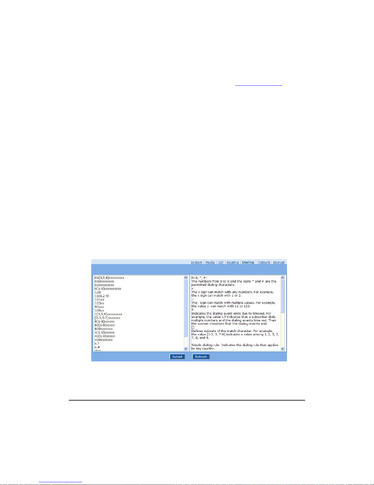
Shanghai New Rock Technologies Inc. Page60/75
4) Replacement
FXS CPN88 REPLACE 2682000
Note: When 8000 is dialed on FXS port, the call will be routed to port FXS-1.
5) Routing calls to IP network
FXS 0 ROUTE IP www.mysip.com:5060
Note: A call started with 0 will be routed to the SIP proxy with www.mysip.com:5060
.
6) Routing calls to PSTN
IP X ROUTE FXO 1,2,3,4
Note: Calls from IP network will be routed to FXO port 1, 2, 3, and 4 in alternate way.
7) Support POS and Modem
FXS[2] 6120 CODEC PCMU/20/0
Note: Using PCMU for FXS-2 with 20ms of package size. /0 indicates that the echo
cancellation is off.
8) Routing calls to IP network, using given IP trunk
FXS 021 ROUTE IPT 1,2
9) Add prefix
FXS CPNX ADD 021
Note: 021 Add 021 before the calling number when an extension is used to call it out.
2.7.6 Digit Map
After login, click “Advanced > Dialing” tab to open the dialing rules interface.
Figure 2-28 Configuration Interface for Digit Map
Digit map is used to effectively judge if the received number sequence is completed, for the purpose
of ending up receiving numbers and sending out the received numbers. The proper use of digit map
can help to reduce the connection time of telephone calls.
Page 61

Shanghai New Rock Technologies Inc. Page61/75
The maximum number of digit map that can be stored in OM is 60. Each rule can hold not more than
32 numbers and 38 characters. The total length of digit map table (the total length of all digit map)
cannot be more than 2280 bytes.
The default typical rules include constituent rules of domestic phone numbers and function keys used
by the OM. Users can add new rules as required. Basic symbols in typical rules are as follows. The
following table provides a description of typical rules:
Basic symbols:
z 0–9, *, #: the numbers from 0 to 9 and the signs * and # are the permitted dialing characters.
z x: the x sign can match with any numbers. For example, the x sign can match with 1 or 2.
z .: the “.” sign can match with multiple values. For example, the value 1. can match with 11 or
123.
z []: defines subsets of the match character. For example, the value [1-3, 5, 7-9] indicates a value
among 1, 2, 3, 5, 7, 8, and 9.
z T: indicates the dialing event ends due to timeout. For example, the value x.T indicates that a
user dials multiple numbers and the dialing events time out. Then the system considers that the
dialing events end.
Table 2-29 Description of Digit map
Digit map Description
“##”
End after receiving two-digit dialing “##”. “##” is an special dialing
for users to query IP address and version number of firmware by
default.
“x.T”
The OMs will detect any length of telephone number starting with any
number between 0-9. The OMs will send the detected number when it
has exceeded the dialing end time set in system parameter
configuration and hasn’t received a new number.
“x.#”
Any length of telephone number starting with any number between
0-9. If users press # key after dial-up, the OMs will immediately end
up receiving numbers and send all the numbers before # key.
“*xx”
End after receiving * and any two-digit number. "* xx" is primarily
used to activate function keys for extension features, such as CRBT,
Call Transfer, Do not Disturb, etc.
“#xx”
End after receiving # and any two-digit number. “#xx” is primarily
used to stop function keys for extension features, such as CRBT, Call
Transfer, Do not Disturb, etc.
[2-8]xxxxxx
A 7-digit number starting with of any number between 2-8, used to end
the dialing.
02xxxxxxxxx
An 11-digit number starting with 02, used to end the dialing starting
with “02”.
13xxxxxxxxx An 11-digit number starting with 13, used to end the dialing.
11x A 3-digit number starting with 11, used to end the special service calls.
9xxxx A 5-digit number starting with 9, used to end special calls.
2.7.7 Tie trunk
The tie trunk of OM is an IP trunk based on SIP protocol, and it is used to connect more than two
OMs via IP network. Abbreviated dialing, call transfer and other functions among different
extensions of the OM can be achieved in such an OM group. Tie trunk is usually used for: 1)
corporate non-local tie trunk; 2) system expansion. A specific example is used to explain the
application of tie trunk following the introduction of parameter configuration of tie trunk below.
After login, click “Advanced > Tie trunk” tab to open the configuration interface.
Page 62
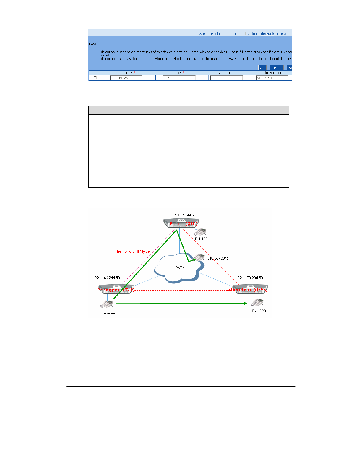
Shanghai New Rock Technologies Inc. Page62/75
Figure 2-29 Configuration interface of tie trunk
Click “Add” to add the devices.
Table 2-30 Configuration parameter of tie trunk
Name Description
IP address Enter the IP address of this OM tie trunk.
Prefix
Extension numbers are required to plan overall when the tie trunk is
used. An extension prefix is the prefix part of an extension number, and
each OM has a unique extension prefix; a number created like this is
unique in the whole network; an extension prefix can not be “0” or used
as an added dial of outbound call or front desk.
Area code
An area code is the regional code of fixed-line telephone network in a
place where OM is located; for example, “021”is the zip code in
Shanghai.
Pilot number
Trunk numbers are external numbers of the OM (such as operator
number)
Figure 2-30 Reference Tie Trunk Diagram
Explanation:
1) Dial “323” directly if the extension 201 in Shanghai is used to dial the extension 323 in
Shenzhen.
2) Dial “010-52452345”directly if the extension 201 in Shanghai is used to dial the urban phone
number 010-52452345 in Beijing.
Page 63

Shanghai New Rock Technologies Inc. Page63/75
Table 2-31 Intelligent Routing Table
Examples Dialing and Routing Selection
Dial a Beijing extension in Shanghai
Dial the extension number directly, and it will be
connected to an extension of the OM in Beijing through
tie trunk;
Dial a fixed Beijing phone number
(010) in Shanghai
Dial the Beijing number directly, and it will be outbound
from Beijing OM through tie trunk;
Dial a fixed Beijing phone number
in Shanghai, but it is outbound from
Shanghai.
Dial “9” and then the Beijing number;
Dial a fixed Jiangsu phone number
in Shanghai
Dial this number directly and it is outbound from the
local OM; or dial “9” and then this number.
Dial a fixed Jiangsu phone number
in Shanghai, but it is outbound from
Shanghai.
Dial “9” and then the Jiangsu number;
Dial a mobile phone in Shanghai Dial “9” and then the mobile phone number;
Dial a Beijing extension in
Shanghai, but the tie trunk is not
accessed.
Dial the extension number directly and it is connected to
Beijing OM after being outbound locally, then re-dial it
after receiving the voice prompt;
Dialing Rules:
z Dial all extensions directly (including local and non-local extension numbers);
z Add “9” when dialing outbound trunks (Note: The prefix can be set);
z Long-distance fixed phone numbers (starting with “0”) can be dialed directly, or add ”9” to
dial out;
z “9” should always be dialed for mobile phone, or it will be treated as extension if ‘9” is not
dialed.
Table 2-32 Trunk Routing Table of OM Reference Configuration
Prefix Area Code IP Address Pilot Number
2 021 221.166.244.50 61202700
1 010 221.132.199.50 54025012
3 0755 221.133.235.50 78404122
Page 64
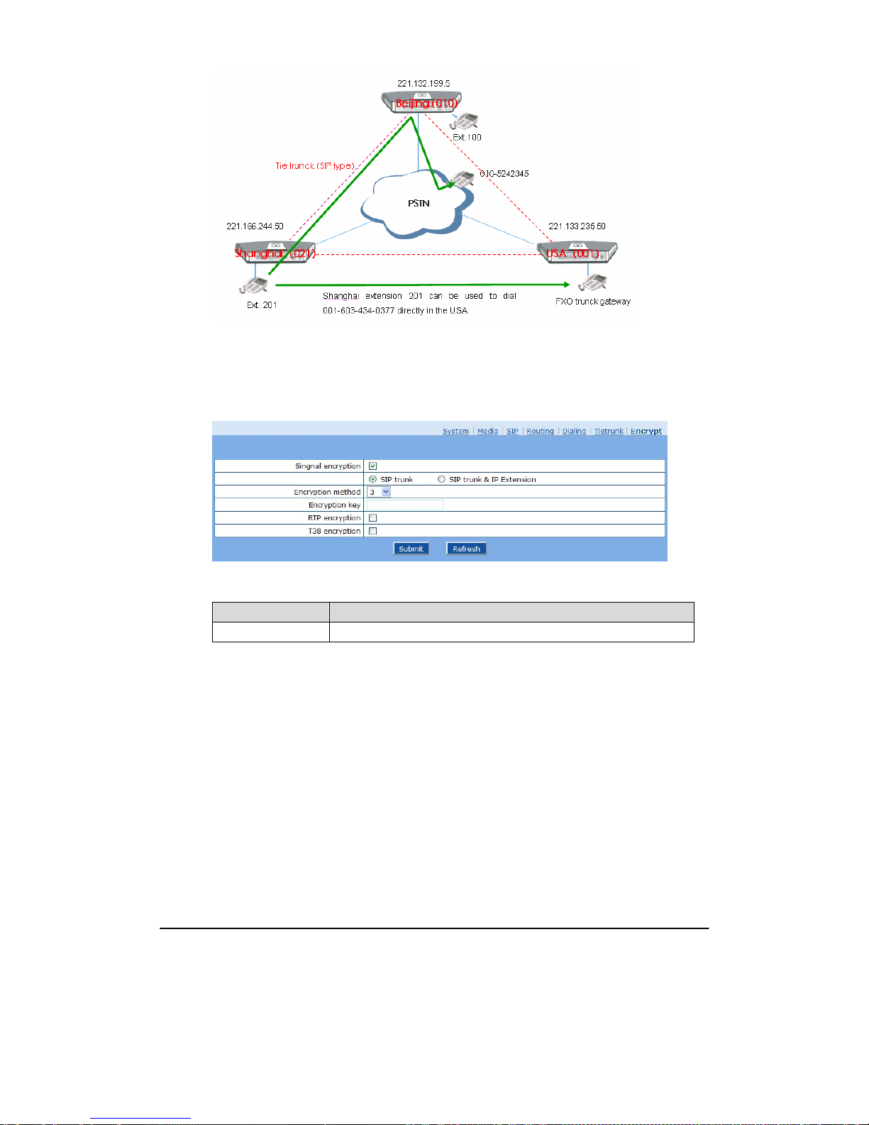
Shanghai New Rock Technologies Inc. Page64/75
Figure 2-31 Tie Trunk Application Diagram in OM
2.7.8 Encrypt
After login, click the label of “Advanced > Encrypt” to open this interface.
Figure 2-32 Encrypt configuration interface
Table 2-33 Encrypt configuration parameters
Name Description
Signaling encryption Choose whether to encrypt signaling. By default, this is not selected.
Page 65

Shanghai New Rock Technologies Inc. Page65/75
Name Description
Encryption method
Select the encryption method, and default is 7. The optional parameters
as below:
z 2: TCP Not Encrypted;
z 3: TCP Encrypted;
z 6: UDP Not Encry pted;
z 7: UDP Encrypted(New Rock);
z 8: Using Keyword;
z 9: Using Keyword2;
z 10: RC4;
z 11: Using Keyword 3;
z 12: Encrypt12;
z 13: Encrypt13;
z 14: Encrypt14(New Rock);
z 16: Word Reverse;
z 17: Word Exchange(263);
z 18: Byte Reverse;
z 19: Byte Exchange.
Encryption key You may obtain it from service provider
RTP encryption
Choose whether to encrypt RTP voice pack, the default is “ not to
activate”
T.38 encryption Choose whether to encrypt T38 data. By default, this is not selected.
2.8
Log management
2.8.1 Resource status
Critical runtime information of OMs can be obtained in this interface, including:
1) The information about login of interface (including IP address and jurisdiction of the user);
2) SIP registration status;
3) Call related signaling and media (RTP) information;
After login, click the label of “Logs > System Status” to open this interface.
Page 66
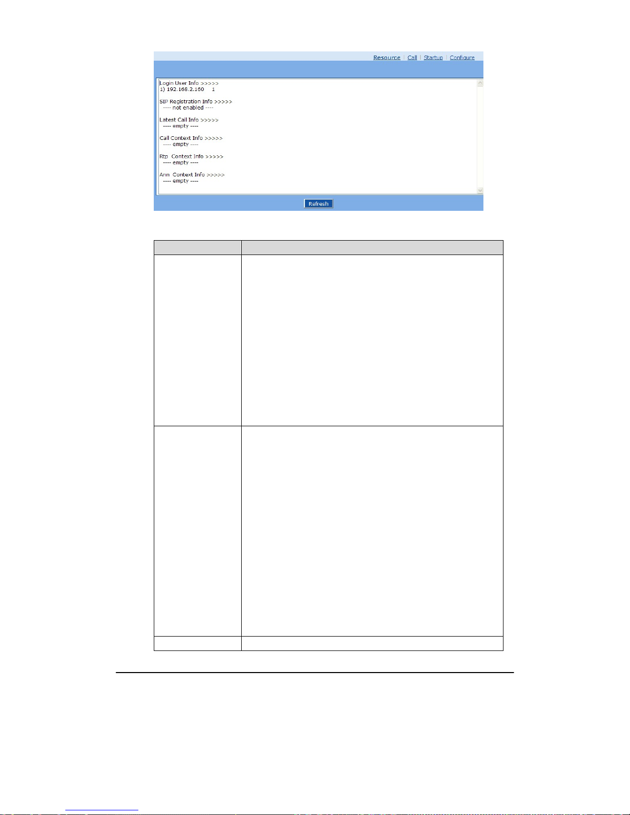
Shanghai New Rock Technologies Inc. Page66/75
Figure 2-33 System Status Interface
Table 2-34 Parameters of system status
Title Explanation
Login User Info
Show the IP address and jurisdiction of login user. The numbers
following the IP address show the online jurisdiction of the user:
1- administrator;
2 - operator;
3 - viewer.
The viewer can only read the configuration, but is not allowed to
modify it.
When more than one administrator log in at the same time, the first
login’s jurisdiction is 1, others are 3; also, when more than one
operators log in at the same time, the first one’s jurisdiction is 2, others
are 3.
For example:
Login User Info >>>>>
1) 192.168.2.247 1
SIP Registration Info Show registration status:
z Not enabled: The registration server’s address is not entered yet;
z Latest response: The latest response message for the registration. 200
means registered successfully;
z No response: Not received response from registration server. The
cause may contribute to 1)incorrect address for the registration
server; 2) IP network fault; or, 3) the registration server is not
reachable.
For example:
SIP Registration Info >>>>>
---- Not enabled ---SIP Registration Info >>>>>
Contact: <sip:[email protected]:1003;user=phone>
latest response: 200 (timeout-555)
Contact: <sip:[email protected]:1003;user=phone>
latest response: 200 (timeout-555)
Call Context Info Show the call status.
Page 67
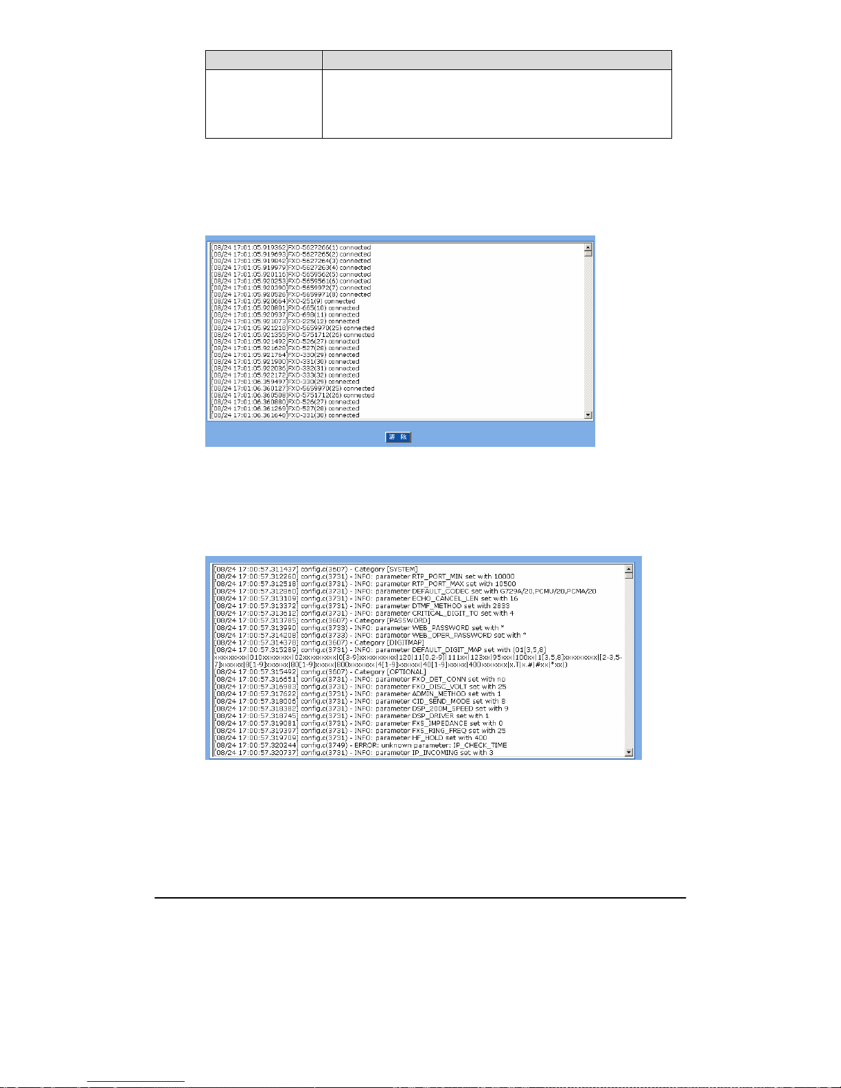
Shanghai New Rock Technologies Inc. Page67/75
Title Explanation
Rtp Context Info
Show the voice channel related to the calls.
For example:
Rtp Context Info >>>>>
3) created, call =e011
2.8.2 Call message
After login, click the label of “Logs > Call Message” to open this interface.
Figure 2-34 Call message interface
2.8.3 System Startup
After login, click the label of “Logs > System Startup” to open this interface. The OM boot up
information is available in this page, including the hardware configuration.
Figure 2-35 Interface of system startup
2.8.4 Configure log
After login, click the label of “Logs > Configure” to open this interface. Log files can be downloaded
through this interface.
Page 68
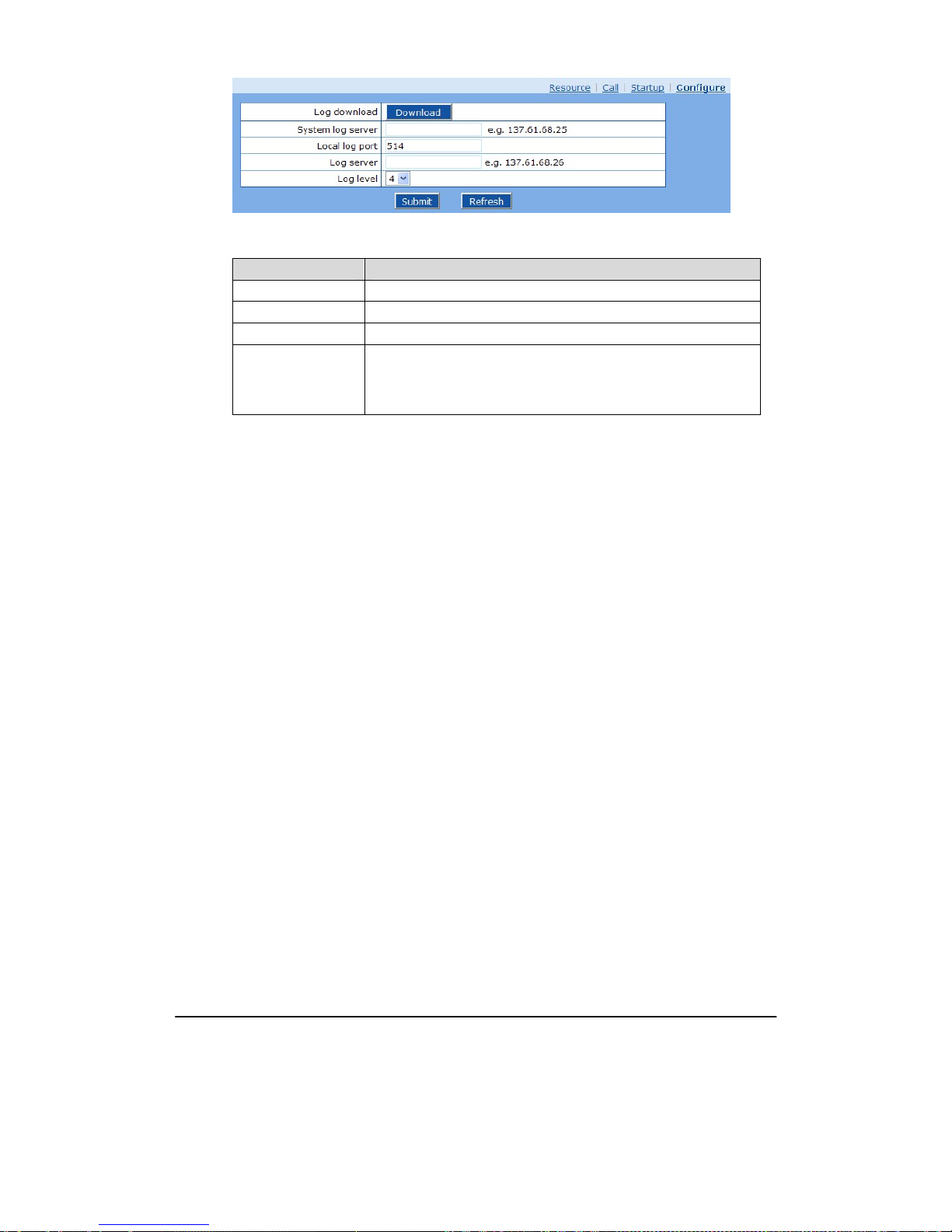
Shanghai New Rock Technologies Inc. Page68/75
Figure 2-36 Interface of debugging log management
Table 2-35 Configuration parameters of debugging log management
Title Explanation
Log download See the description below.
System log server Set the IP address of system log server.
Log server IP address of debugging log server.
Log level
Select the log file level of OM, default is 3. The setting range is 1 ~ 5,
the higher the level goes, the more details the log file will be.
Note: log level should be set to be 3 or lower when OM is used in
normal operation, avoiding influencing the system performance.
Procedure of downloading the debugging log:
Step 1: Click “download”, the OM starts pack the logs.
Step 2: After few seconds, the interface of log save will appear.
Step 3: click “Save”, and select path to save.
Step 4: The user may review the log from the server concerned.
2.9
System tool
2.9.1 Change password
After login, click the label of “Tools” to open this interface. Only administrator is entitled to change
the password of login.
For changing administrator password, it’s required to enter new password into “New password” field
and “Confirm new password” field, then click “Submit”.
The password being used by operator will be displayed as hidden codes, whic h could be cha nged by
administrator at any time. The administrator is allowed to change the operator’s password by entering
new password into “Operator password>password”.
Page 69
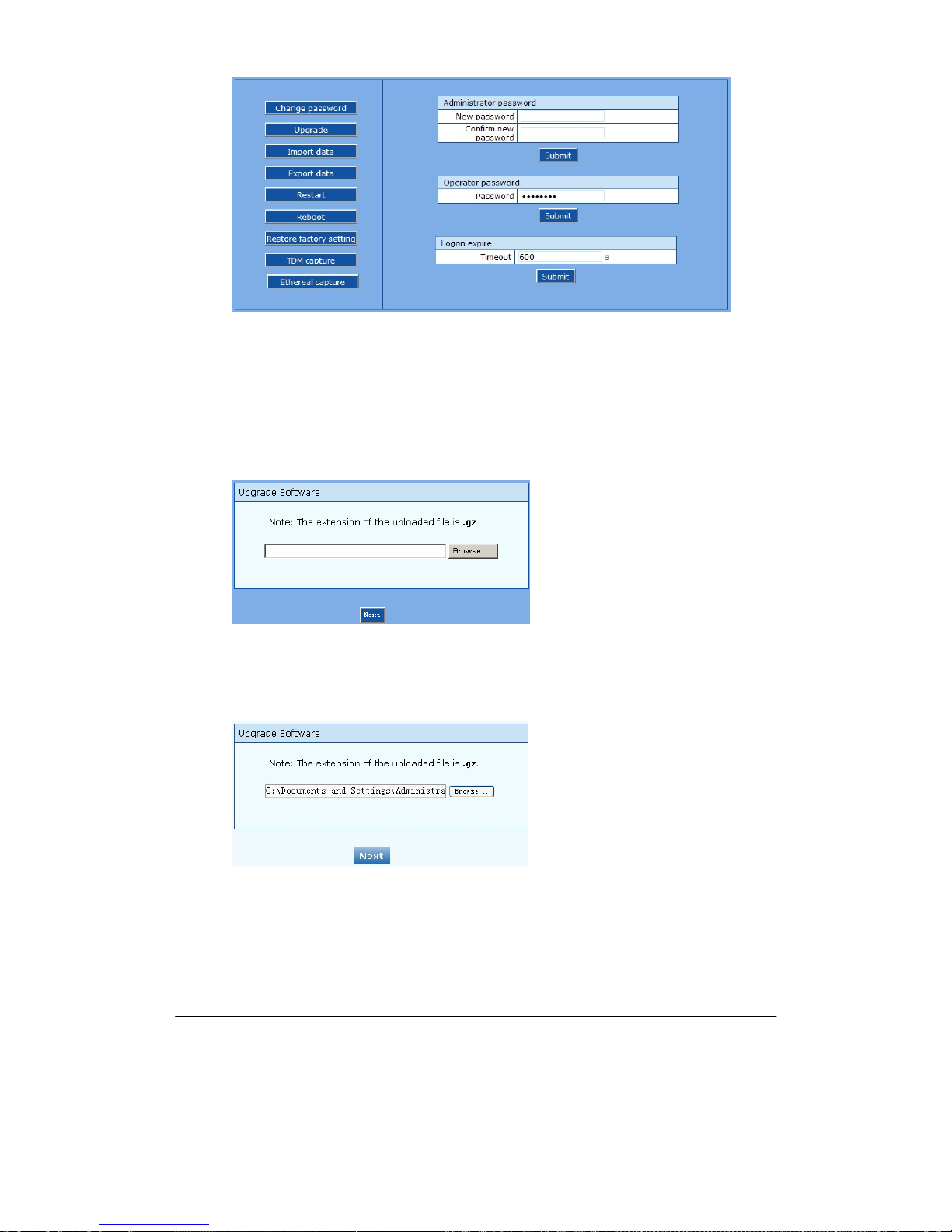
Shanghai New Rock Technologies Inc. Page69/75
Figure 2-37 Interface of password changing
2.9.2 Software upgrade
After login, click “Tools > Upgrade” to open this interface. The software upgrading procedure is
presented as below:
Step 1
Obtain the upgrade files (tar.gz file), and save the file onto a local computer.
Step 2
Click “System tool > software upgrade” to access to the page of software upgrade.
Figure 2-38 Interface of software upgrade
Step 3
Click “Browse” to select the upgrade files and click “Open”.
Step 4
Click “Next” when the following interface appears, and start uploading the upgrade files to the OM.
Figure 2-39 Interface of file upload
Step 5
Uploading will be completed in about 30 seconds, and click “Upgrade” on following dialog.
Page 70
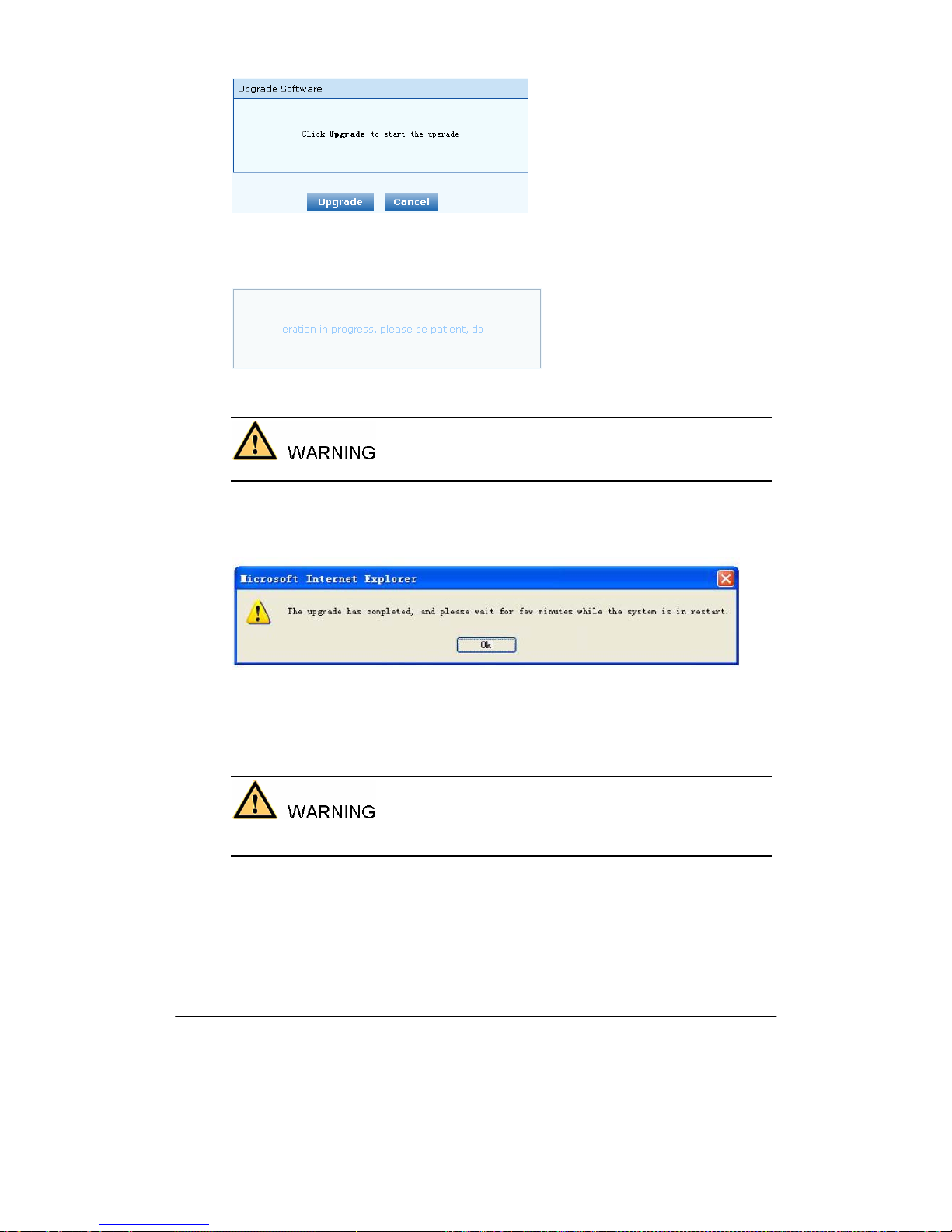
Shanghai New Rock Technologies Inc. Page70/75
Figure 2-40 Upgrade interface
Step 6
The following prompt appears during the upgrade.
Figure 2-41 Prompt of upgrade process
A few minutes are needed to upgrade the OM. Don’t operate the OM during this period.
Step 7
After success in upgrade, the following dialog will appear, click “Confirm”.
Figure 2-42 Interface of successful upgrade
Step 8
The OM will reboot, and the interface will be disappeared.
Step 9
Wait for about 2 minutes, and access to the interface of OM management system, click “Info” and
check the software version.
ForOM100 and OM200, the software upgrade operation must be conducted on an 100M Ethernet
port.
2.9.3 Configuration import
After login, click “Tools>Import data” to open this interface. Operating procedure is the same as that
of “software upgrade”.
Page 71
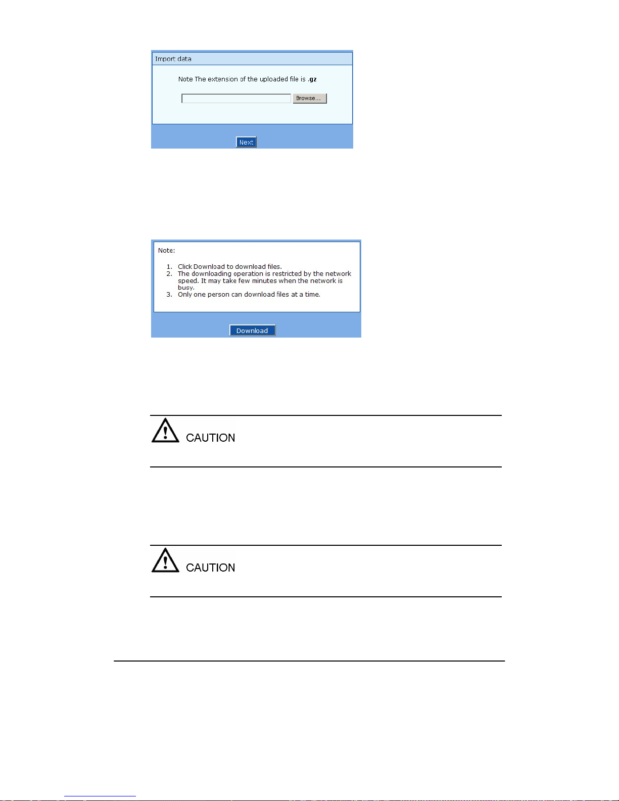
Shanghai New Rock Technologies Inc. Page71/75
Figure 2-43 Interface of import data
2.9.4 Configuration export
After login, click “Tools >Export of configuration” to open this interface. It’s allowed to download
the configuration files from the OM through this interface. The downloading procedure is similar to
the downloading procedure of log files.
Figure 2-44 Interface of export data
2.9.5 Software restart
After login, click “Tools > Restart” to restart the OM, making modified configuration come into
effect.
In most cases, there is no need to reset the OM, and the modified parameters will come into effect
upon confirming the “submit”.
2.9.6 System reboot
After login, click “Tools >Reboot” to restart the OM. As this is a system wide reset, it takes longer
time.
Generally, it’s sufficient to restart software when the OM confirms to reset; the system reboot will be
required only when network settings of the OM are changed.
Page 72

Shanghai New Rock Technologies Inc. Page72/75
2.9.7 Restore factory settings
After login, click “Tools > Restore factory settings” to restore the parameters of OM into the factory
settings.
The factory settings are designed based on common applications, and therefore, no need to modify
them in many deployment situations.
2.9.8 TDM Capture
After login, click “Tools > TDM Capture” to open the capture interface.….
This tool is used to capture the received TDM signal on a FXS or FXO port. The maximum length of
the capture is 200 seconds. The capture is stored in the flash memory of the device in TDM format,
which is readable with reader such as CoolEditor.
Capture process:
Step 1
Selecting by clicking
, or manually enter the port from which you want to capture the TDM
signal.
Step 2
Click “Start” to begin the capture process.
Step 3
Click “Stop” to end the capture. You will be prompt to download. Download the capture file to the
designated PC.
2.9.9 Ethereal capture
After login, click “Tools > Ethereal capture” to open the interface of the tool.….
This tool is used to capture the tcpdump of the device. Up to 3 files each with Max. 3 M bytes in size
can be generated. The captured files are stored on the flash memory of the device in dump.cap format,
which is readable by Ethereal.
Steps for capture:
Step 1
Click “Start” to begin the capture process. You will be notified if there is a on-going capture already.
Step 2
Making the call which you want to capture.
Step 3
Click “Stop” to end the capture process. You will be notified for download. Download the file to the
designated PC.
2.10
Product information
After login, click “Info” to view the OM hardware and software version information.
Figure 2-45 Configuration interface of product information
Page 73

Shanghai New Rock Technologies Inc. Page73/75
2.11
Logout
After login, click the “Logout” at top right to exit the management system and return to the login
interface.
Page 74

Shanghai New Rock Technologies Inc. Page74/75
3 Appendix
3.1
OM200
system operation state
Table 3-1 OM200 system operation state
Glittery letter Status meaning
“C”
The IP address of OM conflicts with that of other equipment in LAN.
Please settle this problem before the OM can be operated normally.
“D”
Internal failures have been encountered during OM start up procedure.
Please contact your local distributor for further diagnosis.
“P”
The OM is in progress of system software upgrade. Please guarantee
stable power supply and do not conduct other operations during this
period.
“T”
The application software of OM has been exited. If it can not be restored
by rebooting the system, please contact your local distributor for further
diagnosis.
3.2
Setting of Recording Storage Server
Table 3-2 Hardware Requirements for Recording Storage Sever
Item Minimum Configuration Recommended Configuration
CPU P4 2.4G Xeon 3.0G (Dual core)
Memory 500M 1G
HD
According to the need (recording
170KB/min.)
According to the need (recording
170KB/min.)
Port (communicating
with OM)
1311 1311
OS Windows 2003/XP Windows 2003/XP
Table 3-3 Specification of OM Recording
Item Description
Voice Coding
Recording can operate normally when the OM selects G.711 or
G.729A/B.
Recorded file format MP3
Player
Users can play the calling and called voices through L&R sound
channels
Performance A maximum of 24-way recording can be done at one time.
Voice Monitoring Not support
Page 75

Shanghai New Rock Technologies Inc. Page75/75
The installation steps of recording software are as follows:
Step 1
Copy OMRecord.exe, Install.cmd and Uninstall.cmd to the installation directory on Windows XP
(storage server);
Step 2
Click to install Install.cmd. After installation, the recording software will run in the background by
the name of “OMRecord”. It will run automatically after startup each time;
Step 3
Ensure that port 1311 on the storage server running OMRecord.exe has not been screened by the
firewall.
Notes:
1) Recorded files (MP3 in format) are stored under the directory of omrecord.exe;
2) Naming format of recorded files: calling number_called number_day/month/
year/-hour/minute/second.mp3.
 Loading...