

Page 1

MX Series Voice Gateway User Manual
New Rock Technologies, Inc.
MX Series Voice Gateway
User Manual
HX4E
MX8A
MX60
MX60E
MX120G
Page 2

User Manual MX Series Voice Gateway
Copyright © 2017 New Rock Technologies, Inc. All Rights Reserved.
All or part of this document may not be excerpted, reproduced and transmitted in any form
Amendment Records
Document Rev. 02 (March 2017)
Added MX60E, and removed MX120. This manual is applicable to New Rock's MX series Voice
Gateway V351.
Document Rev. 01 (June 2016)
This manual is applicable to New Rock’s MX series Voice Gateway V344.
Page 3

MX Series Voice Gateway User Manual
Contents
Amendment Records ............................................................................................................................... 2
Contents ....................................................................................................................................................... 3
Figures ......................................................................................................................................................... 7
Tables ........................................................................................................................................................ 10
1 Overview .............................................................................................................................................. 14
1.1 Product Introduction ............................................................................................................................................................... 14
1.2 Functions and Features .......................................................................................................................................................... 15
1.3 Equipment Structure ............................................................................................................................................................... 16
1.3.1 HX4E ................................................................................................................................................................................. 16
1.3.2 MX8A ............................................................................................................................................................................... 18
1.3.3 MX60 ................................................................................................................................................................................ 21
1.3.4 MX60E ............................................................................................................................................................................. 24
1.3.5 MX120G .......................................................................................................................................................................... 27
1.4 Web Management Page ........................................................................................................................................................ 32
1.4.1 Layout .............................................................................................................................................................................. 32
1.4.2 Buttons Used on Gateway Management Interface ......................................................................................... 32
2 Parameters Setting ............................................................................................................................. 33
2.1 Login ............................................................................................................................................................................................. 33
2.1.1 Obtaining Gateway IP Address ............................................................................................................................... 33
2.1.2 Logging On to Web GUI ........................................................................................................................................... 33
2.1.3 Gateway Administrator and Operator Rights (Web GUI) .............................................................................. 34
2.1.4 Accessing Through SSH ............................................................................................................................................ 35
2.1.5 SSH user Permissions ................................................................................................................................................. 36
2.2 Basic Configuration .................................................................................................................................................................. 36
2.2.1 Status ............................................................................................................................................................................... 36
2.2.2 Network .......................................................................................................................................................................... 36
2.2.3 VLAN ................................................................................................................................................................................ 38
New Rock Technologies, Inc. 3
Page 4

User Manual MX Series Voice Gateway
2.2.4 System ............................................................................................................................................................................. 40
2.2.5 SIP ..................................................................................................................................................................................... 42
2.2.6 High Availability ........................................................................................................................................................... 44
2.2.7 TLS&SRTP ....................................................................................................................................................................... 45
2.2.8 MGCP ............................................................................................................................................................................... 46
2.2.9 FoIP ................................................................................................................................................................................... 48
2.2.10 Alarm ............................................................................................................................................................................. 50
2.3 Line ................................................................................................................................................................................................ 52
2.3.1 Phone Number ............................................................................................................................................................. 52
2.3.2 Subscriber Line Features ........................................................................................................................................... 52
2.3.3 Subscriber Line Batch (Unavailable on the HX4E) ........................................................................................... 55
2.3.4 Subscriber Line Characteristics ............................................................................................................................... 56
2.4 Trunk ............................................................................................................................................................................................. 59
2.4.1 Phone Number ............................................................................................................................................................. 59
2.4.2 Trunk Features .............................................................................................................................................................. 60
2.4.3 Trunk Batch (Unavailable on the HX4E) .............................................................................................................. 61
2.4.4 Trunk Characteristics .................................................................................................................................................. 62
2.5 Routing ......................................................................................................................................................................................... 64
2.5.1 Digit Map ....................................................................................................................................................................... 64
2.5.2 Routing Table ............................................................................................................................................................... 66
2.5.3 Examples of Routing Rules ...................................................................................................................................... 70
2.6 Advanced Configuration ........................................................................................................................................................ 71
2.6.1 System ............................................................................................................................................................................. 71
2.6.2 Auto Provisioning ........................................................................................................................................................ 73
2.6.3 Management System Type ...................................................................................................................................... 74
2.6.4 Certificate (Available on the HX4E/MX8A) ......................................................................................................... 75
2.6.5 Media Stream ............................................................................................................................................................... 76
2.6.6 SIP Configuration ........................................................................................................................................................ 78
2.6.7 RADIUS (Unavailable on the HX4E)....................................................................................................................... 81
2.6.8 Greeting .......................................................................................................................................................................... 82
2.6.9 Call Progress Tone Plan............................................................................................................................................. 83
2.6.10 Feature Access Codes .............................................................................................................................................. 84
2.6.11 Clock Service ............................................................................................................................................................... 87
2.7 Security ......................................................................................................................................................................................... 89
2.7.1 Access Security ............................................................................................................................................................. 89
2.7.2 Access list ....................................................................................................................................................................... 91
2.7.3 Brute Force Login Prevention ................................................................................................................................. 93
Page 5

MX Series Voice Gateway User Manual
2.7.4 ACL-based Traffic Filtering ............................................................................................................................................ 94
2.7.5 Packet Rate Limiting Based Dynamic Blacklisting ........................................................................................... 95
2.7.6 IP Table ........................................................................................................................................................................... 98
2.7.7 Voice Security ............................................................................................................................................................... 98
2.7.8 Encryption ...................................................................................................................................................................... 99
2.7.9 VPN (Available on the HX4E/MX8A) ................................................................................................................. 100
2.8 Status ......................................................................................................................................................................................... 101
2.8.1 Call Status ................................................................................................................................................................... 101
2.8.2 Call History on FXS................................................................................................................................................... 102
2.8.3 Call History on FXO.................................................................................................................................................. 102
2.8.4 SIP Message Count .................................................................................................................................................. 103
2.9 Logs ............................................................................................................................................................................................ 103
2.9.1 System Status ............................................................................................................................................................ 103
2.9.2 Call Message .............................................................................................................................................................. 104
2.9.3 System Startup .......................................................................................................................................................... 105
2.9.4 Manage Log ............................................................................................................................................................... 105
2.10 Tools ........................................................................................................................................................................................ 107
2.10.1 Configuration Management .............................................................................................................................. 107
2.10.2 Upgrade .................................................................................................................................................................... 108
2.10.3 Restore Factory Settings ..................................................................................................................................... 109
2.10.4 Capture Recordings on the Port ....................................................................................................................... 110
2.10.5 IP Capture ................................................................................................................................................................. 110
2.10.6 Network Diagnosis (HX4E/MX8A).................................................................................................................... 110
2.11 Product Information........................................................................................................................................................... 111
2.12 Reboot .................................................................................................................................................................................... 111
2.13 Logout ..................................................................................................................................................................................... 111
3 Appendix: VLAN Configuration ...................................................................................................... 112
3.1 Automatic Discovery ............................................................................................................................................................ 112
3.1.1 LLDP .............................................................................................................................................................................. 113
3.1.2 DHCP ............................................................................................................................................................................. 116
3.2 Manual Configuration .......................................................................................................................................................... 118
3.2.1 Single VLAN ................................................................................................................................................................ 118
3.2.2 Multi-Service VLAN ................................................................................................................................................. 119
New Rock Technologies, Inc. 5
Page 6

User Manual MX Series Voice Gateway
4 Making an OpenVPN Client Certification (HX4E/MX8A) ............................................................. 125
5 Appendix: High availability configuration ..................................................................................... 128
6 Appendix: Auto provisioning configuration ................................................................................. 129
Page 7

MX Series Voice Gateway User Manual
Figures
Figure 1-0 HX4E Front Panel ....................................................................................................................................................... 17
Figure 1-1 HX4E Back Panel ......................................................................................................................................................... 17
Figure 1-2 MX8A Front Panel ...................................................................................................................................................... 19
Figure 1-3 MX8A Back Panel ....................................................................................................................................................... 19
Figure 1-4 RJ45 to RS232 Serial Cable ..................................................................................................................................... 20
Figure 1-5 USB to RS232 Converter Cable ............................................................................................................................. 20
Figure 1-6 MX60 Front Panel ...................................................................................................................................................... 22
Figure 1-7 Schematic Diagram of MX60 Subscriber Line Connection ......................................................................... 23
Figure 1-8 MX60 Back Panel-AC ................................................................................................................................................ 23
Figure 1-9 MX60 Back Panel-DC ................................................................................................................................................ 23
Figure 1-10 MX60E Front Panel .................................................................................................................................................. 25
Figure 1-11 Schematic Diagram of MX60E Subscriber Line Connection ..................................................................... 26
Figure 1-12 MX60E Back Panel-AC ........................................................................................................................................... 26
Figure 1-13 MX120G Front Panel .............................................................................................................................................. 28
Figure 1-14 Schematic Diagram of MX120G Subscriber Line Connection ................................................................. 29
Figure 1-15 MX120G Back Panel-AC ........................................................................................................................................ 30
Figure 1-16 MX120G Back Panel-DC ........................................................................................................................................ 30
Figure 1-17 Web GUI...................................................................................................................................................................... 32
Figure 2-18 Login Interface for MX8A Gateway Configuration ...................................................................................... 34
Figure 2-19 Status Interface ........................................................................................................................................................ 36
Figure 2-20 Network Configuration Interface (HX4E/MX8A) .......................................................................................... 37
Figure 2-21 Network Configuration Interface (MX60/MX60E/MX120G) .................................................................... 37
Figure 2-22 VLAN Configuration Interface ............................................................................................................................. 39
Figure 2-23 System Configuration Interface .......................................................................................................................... 41
Figure 2-24 SIP Configuration Interface .................................................................................................................................. 43
Figure 2-25 High Availability Configuration Interface ....................................................................................................... 44
Figure 2-26 TLS&SRTP Configuration Interface ................................................................................................................... 45
Figure 2-27 MGCP Configuration Interface ........................................................................................................................... 46
Figure 2-28 Fax Configuration Interface (HX4E/MX8A) ..................................................................................................... 48
Figure 2-29 MX60/MX60E/MX120G Fax Configuration Interface .................................................................................. 49
Figure 2-30 Alarm Icon .................................................................................................................................................................. 51
Figure 2-31 Alarms Interface ....................................................................................................................................................... 51
Figure 2-32 Configuration Interface for Batch Configuration (Phone Number) ............................................................. 52
Figure 2-33 Subscriber Line Configuration Interface .......................................................................................................... 53
New Rock Technologies, Inc. 7
Page 8

User Manual MX Series Voice Gateway
Figure 2-34 Feature Batch Configuration Interface ............................................................................................................. 56
Figure 2-35 Subscriber Line Characteristics Configuration Interface ........................................................................... 57
Figure 2-36 Phone Number Configuration Interface .......................................................................................................... 59
Figure 2-37 Trunk Line Features Configuration Interface ................................................................................................. 60
Figure 2-38 Trunk Batch Configuration Interface ................................................................................................................ 62
Figure 2-39 Trunk Characteristics Configuration Interface .............................................................................................. 63
Figure 2-40 Configuration Interface for Digit Map ............................................................................................................. 65
Figure 2-41 Routing Table Configuration Interface ............................................................................................................ 67
Figure 2-42 Interface of system advanced configuration ................................................................................................. 72
Figure 2-43 Interface of Auto Provisioning Configuration ............................................................................................... 73
Figure 2-44 SNMP Configuration Interface............................................................................................................................ 74
Figure 2-45 TR069 Configuration Interface............................................................................................................................ 75
Figure 2-46 Certificate Configuration Interface .................................................................................................................... 76
Figure 2-47 HX4E/MX8A Media Stream Configuration Interface .................................................................................. 76
Figure 2-48 MX60/MX60E/MX120G Media Stream Configuration Interface............................................................. 77
Figure 2-49 SIP Related Configuration Interface ................................................................................................................. 78
Figure 2-50 RADIUS Configuration Interface ........................................................................................................................ 81
Figure 2-51 Greeting Interface ................................................................................................................................................... 82
Figure 2-52 Call Progress Tone Configuration Interface ................................................................................................... 83
Figure 2-53 Feature Codes Configuration Interface ........................................................................................................... 85
Figure 2-54 Clock Service Interface .......................................................................................................................................... 87
Figure 2-55 Access Configuration Interface ........................................................................................................................... 90
Figure 2-56 Access list configuration Interface .................................................................................................................... 91
Figure 2-57 Brute Force Login Prevention (Login Retry Lockout) Configuration Interface .................................. 93
Figure 2-58 Brute Force Login Prevention (Lockout IP Addresses) Interface ............................................................ 94
Figure 2-59 Static Defense Configuration Interface ........................................................................................................... 94
Figure 2-60 Dynamic Defense Configuration Interface ..................................................................................................... 96
Figure 2-61 Dynamic Defense (Blocked IP Addresses) Interface.................................................................................... 97
Figure 2-62 IP Table Configuration Interface ........................................................................................................................ 98
Figure 2-63 Voice Security Configuration Interface ............................................................................................................ 99
Figure 2-64 Encryption Configuration Interface ................................................................................................................... 99
Figure 2-65 VPN Configuration Interface ............................................................................................................................ 101
Figure 2-66 Call Status Interface ............................................................................................................................................. 102
Figure 2-67 Interface of Call History on FXS ....................................................................................................................... 102
Figure 2-68 Interface of Call on FXO ..................................................................................................................................... 102
Figure 2-69 SIP Message Count Interface ........................................................................................................................... 103
Page 9

MX Series Voice Gateway User Manual
Figure 2-70 System Status Interface ...................................................................................................................................... 104
Figure 2-71 Call Message Interface ........................................................................................................................................ 105
Figure 2-72 Interface of System Startup .............................................................................................................................. 105
Figure 2-73 Manage Log Interface ......................................................................................................................................... 106
Figure 2-74 Log Saving Interface ............................................................................................................................................ 107
Figure 2-75 Path Saving Interface .......................................................................................................................................... 107
Figure 2-76 Configuration Management Interface .......................................................................................................... 108
Figure 2-77 Upgrade Interface ................................................................................................................................................ 108
Figure 2-78 Upgrading interface by .img file ..................................................................................................................... 108
Figure 2-79 Upgrade Interface ................................................................................................................................................ 109
Figure 2-80 Restore Factory Settings Interface (HX4E/MX8A) ..................................................................................... 109
Figure 2-81 Restore Factory Settings Interface (MX60/MX60E/MX120G) ............................................................... 109
Figure 2-82 Interface for Capturing Port Recordings ...................................................................................................... 110
Figure 2-83 Ethereal Capture Interface................................................................................................................................. 110
Figure 2-84 Automatic Diagnosis Interface ........................................................................................................................ 111
Figure 2-85 Ping Diagnosis Interface .................................................................................................................................... 111
Figure 3-86 Scenario Diagram ................................................................................................................................................. 114
Figure 3-87 Procedure of Handling LLDP Message Carrying a VLAN ID ................................................................. 115
Figure 3-88 Procedure of Handling the LLDP Message with no VLAN ID ............................................................... 115
Figure 3-89 LLDP Message ........................................................................................................................................................ 116
Figure 3-90 Adding a VLAN ID to the Message to Be Sent .......................................................................................... 116
Figure 3-91 Configuring the Single VLAN ........................................................................................................................... 119
Figure 3-92 A Data Packet Carrying a Corresponding VLAN Tag in the Single VLAN Mode ........................... 119
Figure 3-93 Configuring Voice VLAN to Work in Mode 1 ............................................................................................. 120
Figure 3-94 Configuring Voice VLAN to Work in Mode 2 ............................................................................................. 121
Figure 3-95 Configuring Management VLAN .................................................................................................................... 122
Figure 3-96 Network Environment ......................................................................................................................................... 122
Figure 3-97 Configuring Multi-Service VLAN ..................................................................................................................... 123
Figure 3-98 IP Addresses of the Device in Multi-Service VLAN................................................................................... 123
Figure 3-99 SIP Data Packet Carrying VLAN Tag of the Voice VLAN in the Multi-Service VLAN Mode ....... 124
Figure 3-100 RTP Data Packet Carrying VLAN Tag of the Voice VLAN in the Multi-Service VLAN Mode ... 124
Figure 3-101 RTP Data Packet Carrying VLAN Tag of the Management VLAN in the Multi-Service VLAN Mode
.................................................................................................................................................................................................... 124
New Rock Technologies, Inc. 9
Page 10

User Manual MX Series Voice Gateway
Tables
Table 1-1 MX Series Gateway Hardware Specifications .................................................................................................... 14
Table 1-2 Configuration Combination of HX4E .................................................................................................................... 16
Table 1-3 Description of HX4E Front Panel ............................................................................................................................ 17
Table 1-4 Description of HX4E Back Panel ............................................................................................................................. 17
Table 1-5 Indicator Status of HX4E ........................................................................................................................................... 18
Table 1-6 Configuration Combination of MX8A .................................................................................................................. 18
Table 1-7 Voice Interface Cards Supported by the MX8A ................................................................................................ 19
Table 1-8 Description of MX8A Front Panel .......................................................................................................................... 19
Table 1-9 Description of MX8A Back Panel ........................................................................................................................... 20
Table 1-10 Indicator Status of MX8A ....................................................................................................................................... 20
Table 1-11 Configuration Combination of MX60 ................................................................................................................ 21
Table 1-12 Description of MX60 Front Panel ........................................................................................................................ 22
Table 1-13 Pin Specifications for MX60 RJ45 Socket Port ................................................................................................ 22
Table 1-14 Description of MX60 Back Panel.......................................................................................................................... 23
Table 1-15 Meanings of MX60 Indicators .............................................................................................................................. 24
Table 1-16 Configuration Combination of MX60E .............................................................................................................. 24
Table 1-17 Description of MX60E Front Panel ...................................................................................................................... 25
Table 1-18 Pin Specifications for MX60E RJ45 Socket Port .............................................................................................. 25
Table 1-19 Description of MX60E Back Panel ....................................................................................................................... 26
Table 1-20 Meanings of MX60E Indicators ............................................................................................................................ 27
Table 1-21 MX60E System Operation Status ......................................................................................................................... 27
Table 1-22 MX120G Interface Card ........................................................................................................................................... 27
Table 1-23 Configuration Combination of MX120G ........................................................................................................... 28
Table 1-24 Description of MX120G Front Panel ................................................................................................................... 28
Table 1-25 Pin Specifications for MX120G RJ45 Socket Port .......................................................................................... 28
Table 1-26 Corresponding Relation Between MX120G RJ45 Socket and Line Number ........................................ 29
Table 1-27 MX120G Back Panel ................................................................................................................................................. 30
Table 1-28 Meanings of MX120G Indicators ......................................................................................................................... 31
Table 1-29 MX120GSystem Operation State ......................................................................................................................... 31
Table 1-30 Web GUI Layout Description ................................................................................................................................. 32
Table 2-1 Default IP Address of Gateway ............................................................................................................................... 33
Table 2-2 Default Passwords for logging to Web GUI ....................................................................................................... 34
Table 2-3 Network Configuration Parameters ...................................................................................................................... 37
Table 2-4 VLAN Configuration Parameters ............................................................................................................................ 39
Page 11

MX Series Voice Gateway User Manual
Table 2-5 System Configuration Parameters ......................................................................................................................... 41
Table 2-6 Codec Methods Supported by Gateways ........................................................................................................... 42
Table 2-7 SIP Configuration Parameters ................................................................................................................................. 43
Table 2-8 Parameters ..................................................................................................................................................................... 44
Table 2-9 TLS&SRTP Configuration Parameter .................................................................................................................... 46
Table 2-10 MGCP Configuration Parameters ........................................................................................................................ 47
Table 2-11 Fax Configuration Parameters .............................................................................................................................. 49
Table 2-12 Alarm Type .................................................................................................................................................................. 50
Table 2-13 Configuration Parameters of Batch Configuration (Phone Number) ........................................................... 52
Table 2-14 Subscriber Line Configuration Parameters ...................................................................................................... 53
Table 2-15 Subscriber Line Characteristics Configuration Parameter .......................................................................... 57
Table 2-16 Configuration Parameters of FXO Phone Number ....................................................................................... 59
Table 2-17 Configuration Parameters of Trunk Features .................................................................................................. 60
Table 2-18 Trunk Characteristics Configuration Parameter ............................................................................................. 63
Table 2-19 Description of Digit Map ........................................................................................................................................ 65
Table 2-20 Routing Table Format .............................................................................................................................................. 68
Table 2-21 Number Transformations ....................................................................................................................................... 68
Table 2-22 Routing Destination ................................................................................................................................................. 69
Table 2-23 NAT Configuration Parameters ............................................................................................................................ 72
Table 2-24 Auto Provisioning Configuration Parameters ................................................................................................. 73
Table 2-25 SNMP Configuration Parameters ........................................................................................................................ 74
Table 2-26 TR069 Configuration Parameters ........................................................................................................................ 75
Table 2-27 Media Stream Configuration Parameter ........................................................................................................... 77
Table 2-28 SIP Related Configuration Parameter ................................................................................................................ 79
Table 2-29 RADIUS Configuration Parameter ....................................................................................................................... 82
Table 2-30 Greeting Configuration Parameters ................................................................................................................... 83
Table 2-31 Call Progress Tone Configuration Parameters ................................................................................................ 83
Table 2-32 Feature Codes Configuration Parameter .......................................................................................................... 85
Table 2-33 Clock Service Parameters ....................................................................................................................................... 88
Table 2-34 Access security setting parameters .................................................................................................................... 90
Table 2-35 Login Retry Lockout Parameters.......................................................................................................................... 93
Table 2-36 Brute Force Login Prevention (Lockout IP Addresses) Information ........................................................ 94
Table 2-37 Static Defense Configuration Parameters ........................................................................................................ 94
Table 2-38 Dynamic Defense (Rule Configuration) Parameters ..................................................................................... 96
Table 2-39 Dynamic Defense (Blocked IP Addresses) Information ............................................................................... 97
Table 2-40 Subsequent choices for moving the Blocked IP Addresses to static defense ..................................... 97
New Rock Technologies, Inc. 11
Page 12

User Manual MX Series Voice Gateway
Table 2-41 Encryption Configuration Parameters ............................................................................................................... 99
Table 2-42 VPN Configuration Parameters ......................................................................................................................... 101
Table 2-43 System Status Parameters ................................................................................................................................... 104
Table 2-44 Log Management Configuration Parameters .............................................................................................. 106
Page 13

MX Series Voice Gateway User Manual
New Rock Technologies, Inc. 13
Page 14

MX Series Voice Gateway User Manual
Model
Voic
e
ports
Chassis
Installation
CPU
RAM
Flash
Power
HX4E
2 - 4
Plastic Casing
Desktop
MIPS34Kc,
700MHz, SOC
64MB
16MB
12 VDC
MX8A
4 - 8
Metal
Desktop or rack
MIPS34Kc,
700MHz, SOC
128MB
16MB
12 VDC
MX60
16 - 48
19-inch wide
and 1U High
Rack
AT91SAM9G20B
64MB
16MB
100-240
VAC, -48
VDC
(Optional)
MX60E
16 - 48
19-inch wide
and 1U High
Rack
TI A8, 1GHz
128MB
32MB
100-240
VAC, -36 to
-72 VDC
(optional)
Dual power
(optional)
MX120G
48- 96
19-inch wide
and 2U High
Rack
TI A8, 1GHz
256MB
32MB
100-240
VAC, -36 to
-72 VDC
(optional)
Dual power
(optional)
1 Overview
1.1 Product Introduction
MX Series intelligent VoIP Gateways (MX Gateways) are designed to bridge the traditional telecom
terminal device into IP networks through SIP or MGCP protocols. The main applications include:
For carriers and value-added service providers to provide telephone, fax and voice-band data services
to subscribers using IP access methods such as FTTB, HFC, and ADSL;
To bridge the traditional telecom terminal equipment, such as PBXs, to the VoIP core networks of
carriers;
To connect with an enterprise PBX to provide IP-based voice private network solutions for
institutions, enterprises and schools;
To be used as remote access equipment for IP-PBXs in call center deployment
The MX family has four sub-series: HX4E, MX8A, MX60, MX60E and MX120G, which mainly differ in
port capacities.
Table 1-1 MX Series Gateway Hardware Specifications
New Rock Technologies, Inc. 14
Page 15

MX Series Voice Gateway User Manual
Hardware for MX series gateways uses high-performance CPUs, ensuring that each product of the series
can achieve full-capacity concurrent calls with high speech quality.
MX gateways software adopts the stable and reliable embedded Linux operating system (OS),
implementing scores of business phone functions, including: call forwarding, call transfer, call hold,
teleconference, caller identification, Do Not Disturb, ring-back tone, hunt group simultaneous ring,
distinctive ring, one phone with two numbers, and fax. In addition, MX gateways are featured with FXO
port second stage dialing with voice prompt, routing table with a maximum of 500 entries, phone digit
manipulation, and PSTN failover upon power-off or network disconnection.
MX gateways support local and remote management operations through Web GUI or SSH, SNMPv2based and TR069/TR104/TR106-based centralized management schemes, and auto provisioning.
Maintenance tasks such as modifying configuration, upgrading software, collecting statistical data,
downloading logs, and fault alarms can be performed.
Note: PSTN failover upon power-off or network disconnection is supported by devices with both the FXS
port and the FXO port.
1.2 Functions and Features
Connect analog telephone, PBX, facsimile machine and POS machine to the IP core network, or
PSTN
Work with a service platform to provide various telephone supplementary services
Support protocols: SIP, MGCP
Support STUN. Detecting changes of the reflexive address of the device via STUN, and then
triggering re-registration to the SIP registrar server.
Flexible configuration of subscriber/trunk interfaces
Support G.711, G.729
Support echo cancellation
Up to 500 routing rules can be stored in gateways
Intercom
Support concurrent calls under full load
Support call progress tones for various countries and regions
Support Line second stage dialing or voice prompt
Support PSTN failover on power or network failure
Security strategy: IP filter, encryption
Support PSTN failover through FXO ports
Support G.711 fax pass-through and T.38 fax relay
Support polarity inverse detection and busy tone detection
3-way calling
Compatible with unified communication solutions, such as Call Manager, Lync, Asterisk and Free
SWITCH
Support SNMPv2 and TR069/TR104/TR106
New Rock Technologies, Inc. 15
Page 16

User Manual MX Series Voice Gateway
Models
Number of FXS Ports
Number of FXO Ports
HX402E
2 0 HX420E
0 2 HX422E
2 2 HX440E
0 4 HX404E
4
0
Support Web GUI-based management , SSH, automatic software upgrades, and configuration
downloading
Support high availability, implementing a cloud of SIP servers working in primary-standby or load
balancing mode
Support auto provisioning
Support security settings such as accessing whitelists
Message waiting indications (MWI) with high voltage, FSK, or reversed polarity
Support accessing the Web GUI by using HTTPS
Support Ping blocking
Support optional voice interface cards (only supported by the MX8A/MX120G)
Support the VPN client (only available with the HX4E/MX8A)
Support VLAN
Support New Rock Cloud, allowing New Rock devices located behind NAT or firewall to be easily
accessed.
1.3 Equipment Structure
1.3.1 HX4E
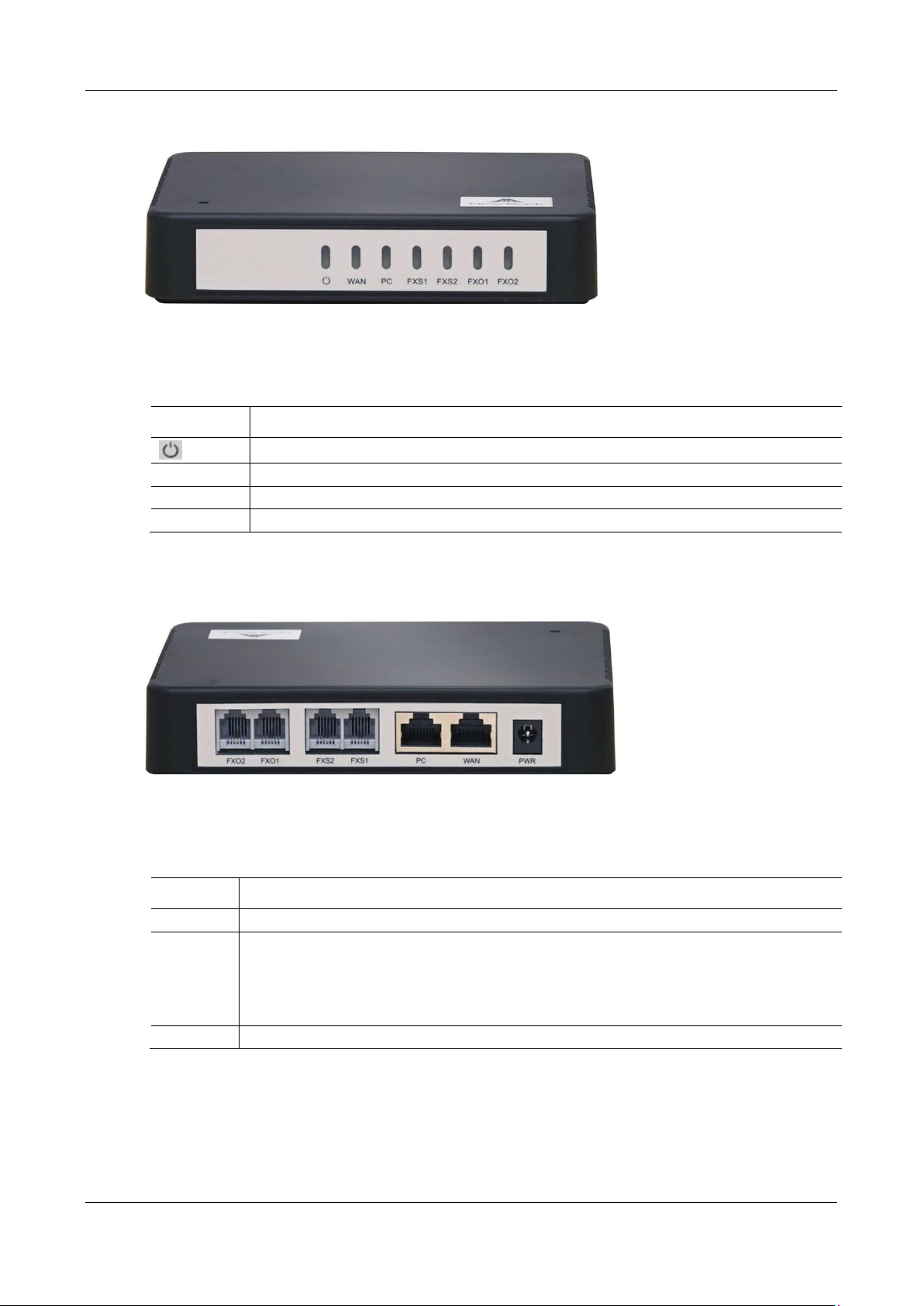
The HX4E adopts a compact plastic structural design and can be placed on a desk.
It provides either two or four FXS/FXO ports.
The HX4E supports the following models.
Table 1-2 Configuration Combination of HX4E
16 New Rock Technologies, Inc.
Page 17
MX Series Voice Gateway User Manual
Item
Description
Power Indicator
WAN
WAN interface indicator
PC
PC interface indicator
FXO/FXS
FXS /FXO port indicator
Item
Description
PWR
Power interface, 12 VDC input
PC and
WAN
The PC port is used to connect a computer.
The WAN port is used to connect the uplink network.
Both are 10/100 Mbps Ethernet ports (RJ45). They share one IP address, which, by default, is obtained
through DHCP. If no IP address is obtained, 192.168.2.218 is used by default, and you can change it on
Basic > Network page.
FXO/FXS
FXS port or FXO port
Figure 1-0 HX4E Front Panel
Table 1-3 Description of HX4E Front Panel
Figure 1-1 HX4E Back Panel
Table 1-4 Description of HX4E Back Panel
New Rock Technologies, Inc. 17
Page 18

User Manual MX Series Voice Gateway
Indicator
Status
Description
PWR(green)
Blinking green
The device is starting.
Steady green
The device is running.
Off
The device is powered off or a power supply fault occurred
STU
(red, green)
Steady red
The WAN interface failed to acquire the IP address. Possibly the WAN
interface is not connected to a network cable, the WAN interface
address failed to be acquired by DHCP, the IP addresses are conflicted,
and the PPPoE dialing failed.
Blinking red
The device is starting or the KUPDATE is upgrading.
Steady green
Registration is successful.
Blinking
alternatively
between red and
green
Registration failed.
Blinking green
Calling.
Off
Registration has not started.
WAN
(green)
Steady green
A WAN connection is established without any service flow.
Blinking green
A WAN connection is established with service flow.
Off
WAN interface is disconnected.
PC
(green)
Steady green
A link is connected without any service flow.
Blinking green
A service flow is being transmitted.
Off
A link is not connected.
FXS/FXO
(green)
Steady green
Off-hook or call established
Blinking green
Ringing on incoming call
Off
The port is in idle status
Models
Number of FXS Ports
Number of FXO Ports
MX8A-4S/4
4 4 MX8A-8S
8 0 MX8A-8FXO
0
8
Table 1-5 Indicator Status of HX4E
1.3.2 MX8A
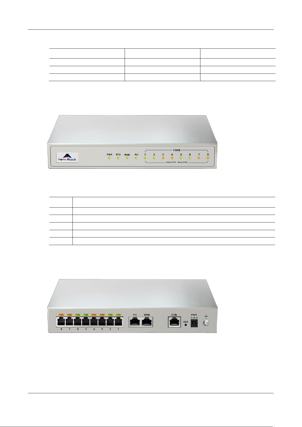
The MX8A adopts a compact metal structural design. It can be placed on a desk or installed in a standard
communications cabinet and provides eight analog ports. MX8A supports the following types of
configuration.
Table 1-6 Configuration Combination of MX8A
18 New Rock Technologies, Inc.
Page 19
MX Series Voice Gateway User Manual
Voice Interface Card Types
Number of FXS Ports
Number of FXO Ports
401A-4FXS
4
0
401A-4FXO
0
4
401A-2FXS/2FXO
2
2
Item
Description
PWR
Power indicator
STU
Status indicator
WAN
WAN interface indicator
PC
PC interface indicator
VOICE
FXS/FXO port indicator
Table 1-7 Voice Interface Cards Supported by the MX8A
Figure 1-2 MX8A Front Panel
Table 1-8 Description of MX8A Front Panel
Figure 1-3 MX8A Back Panel
New Rock Technologies, Inc. 19
Page 20
User Manual MX Series Voice Gateway
Item
Description
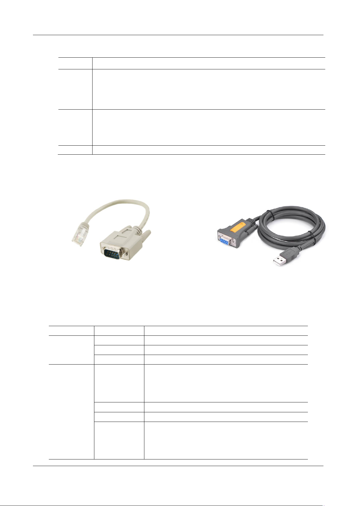
CON
The console port is used for local management and testing. PCs can be connected to device by linking
the RS232 port to CON port.
Connecting cables need to be produced or purchased.
If the connection is established between the device and the mobile PC with no RS232 ports, please use
the cable together with a USB to an RS232 converter cable.
Cables are shown below in Figure 1-4 and Figure 1-5.
PC/WAN
The PC port is used to connect a computer.
The WAN port is used to connect the uplink network.
Both are 10/100 Mbps Ethernet ports (RJ45). They share one IP address, which, by default, is obtained
through DHCP. If no IP address is obtained, 192.168.2.218 is used by default, and you can change it on
Basic > Network page.
FXO/FXS
FXS port or FXO port
Figure 1-4 RJ45 to RS232 Serial Cable
Figure 1-5 USB to RS232 Converter Cable
Indicator
Status
Description
PWR (green)
Blinking green
The device is starting.
Steady green
The device is running.
Off
The device is powered off or a power supply fault occurred.
STU
(red, green)
Steady red
The WAN interface failed to acquire the IP address. Possibly the WAN
interface is not connected to a network cable, the WAN interface
address fails to be acquired by DHCP, the IP addresses are conflicted,
and the PPPoE dialing fails.
Blinking red
The device is starting or the KUPDATE is upgrading.
Steady green
Registration is successful.
Blinking
alternatively
between red and
green
Registration failed.
Table 1-9 Description of MX8A Back Panel
Table 1-10 Indicator Status of MX8A
20 New Rock Technologies, Inc.
Page 21

MX Series Voice Gateway User Manual
Indicator
Status
Description
Blinking green
Calling
Off
Registration has not started.
WAN
(green)
Steady green
A WAN connection is established without any service flow.
Blinking green
A WAN connection is established with service flow.
Off
WAN interface is disconnected.
PC
(green)
Steady green
A link is connected without any service flow.
Blinking green
A service flow is being transmitted.
Off
A link is not connected.
VOICE
(Green-FXS,
yellow-FXO)
Indicates line type and device status:
Blinking yellow
The device is starting and the port is an FXO port.
Blinking green
The device is starting and the port is an FXS port.
Off
No line is detected. Possibly the voice interface card is not inserted or
the port is damaged.
Indicates running status:
Steady yellow
Calling in or out via an analog trunk.
Blinking yellow
Ringing of calling in for an analog trunk.
Steady green
Off-hook or call established
Blinking green
Ringing on incoming call
Off
The port is in idle status
Note: The device starts up for approximate 30s to indicate line type, then indicates running
status.
Indicator of button:
RST
To restore the MX8A to factory default, press the RST for more than 3 seconds and release it
when the STU light starts blinking in red. This setting will be valid after rebooting the device.
Models
Number of FXS Ports
Number of FXO Ports
MX60-16S
16 0 MX60-32S
32
0
MX60-48S
48 0 MX60-16FXO
0
16
MX60-32FXO
0
32
MX60-48FXO
0
48
MX60-8S/8
8
8
1.3.3 MX60
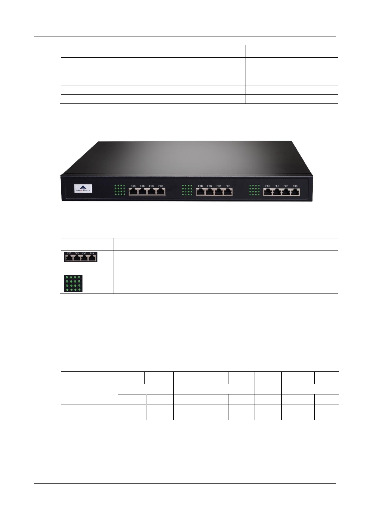
Designed with a 1U high and 19-inch wide compact chassis, MX60 is suitable for installation in a standard
cabinet. MX60 has a built-in power module with the rating voltage of 100-240 V AC or -48 V DC (DC is
optional). The interface card of MX60 uses a RJ-45 socket and is connected to the distribution panel in
equipment room using CAT-5 cables supplied with the unit. MX60 offers up to 48 interfaces of FXS/FXO.
MX60 supports the following types of configuration.
Table 1-11 Configuration Combination of MX60
New Rock Technologies, Inc. 21
Page 22
User Manual MX Series Voice Gateway
Models
Number of FXS Ports
Number of FXO Ports
MX60-24S/8
24 8 MX60-40S/8
40
8
MX60-16S/16
16
16
MX60-32S/16
32
16
MX60-24S/24
24
24
Item
Description
Three interface slots; each can correspond with four RJ45 sockets; each RJ45socket can
correspond with four pairs of analog lines.
Note: Numbers of interface slots vary from different configuration.
Matrix of 4 x 4 LED status indicators on interface card.
RJ45 Pin Number
1 2 3 4 5 6 7
8
Analog line pair
1st Pair
2nd Pair
3rd Pair
2nd Pair
4th Pair
TIP1
RING1
TIP2
TIP3
RING3
RING2
TIP4
RING4
Reference color
Orange
white
Orange
Green
white
Blue
Blue
white
Green
Brown
white
Brown
Figure 1-6 MX60 Front Panel
Table 1-12 Description of MX60 Front Panel
Each RJ45 socket has 8 pins leading out 4 pairs of analog telephone or trunk lines in agreement with the
pair specifications for Ethernet interfaces, whose corresponding relations can be seen in the table below.
CAT-5 cables are used to connect the interface card and distribution panel in equipment installation.
Standard RJ11 telephone lines can be used to plug in a RJ45 socket. The telephone/trunk lines are connected
to the 3rd pair of pins for simple call test.
Table 1-13 Pin Specifications for MX60 RJ45 Socket Port
22 New Rock Technologies, Inc.
Page 23
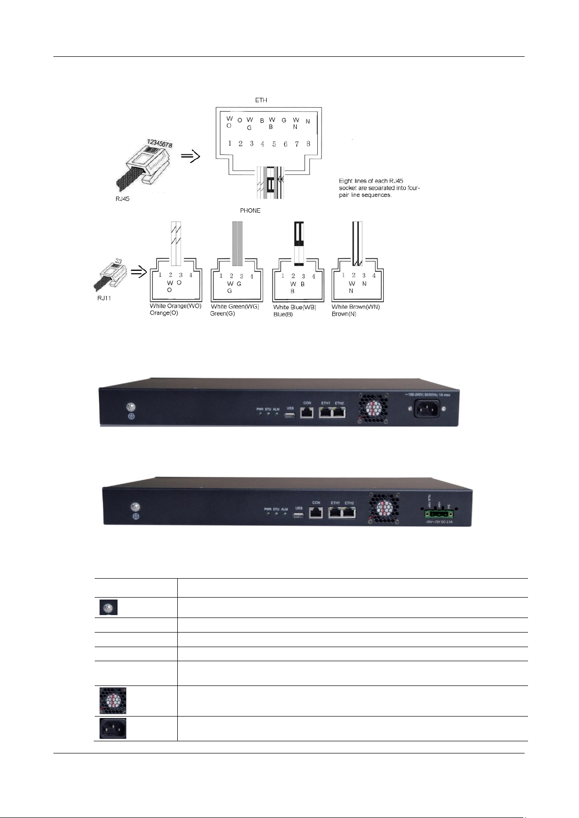
MX Series Voice Gateway User Manual
Item
Description
Ground Pole
PWR/STU/ALM
Indicator, see 0 for description
USB
USB interface
CON
Configuration interface (CON), Ethernet lines used for local management and debugging
ETH1/ETH2
Two 10/100 Mbps Ethernet ports (RJ45). They share one IP address, which by default is
192.168.2.240, and you can change it on Basic > Network page.
Cooling fan
AC power socket, 100-240 VAC voltage input.
Figure 1-7 Schematic Diagram of MX60 Subscriber Line Connection
Figure 1-8 MX60 Back Panel-AC
Figure 1-9 MX60 Back Panel-DC
Table 1-14 Description of MX60 Back Panel
New Rock Technologies, Inc. 23
Page 24
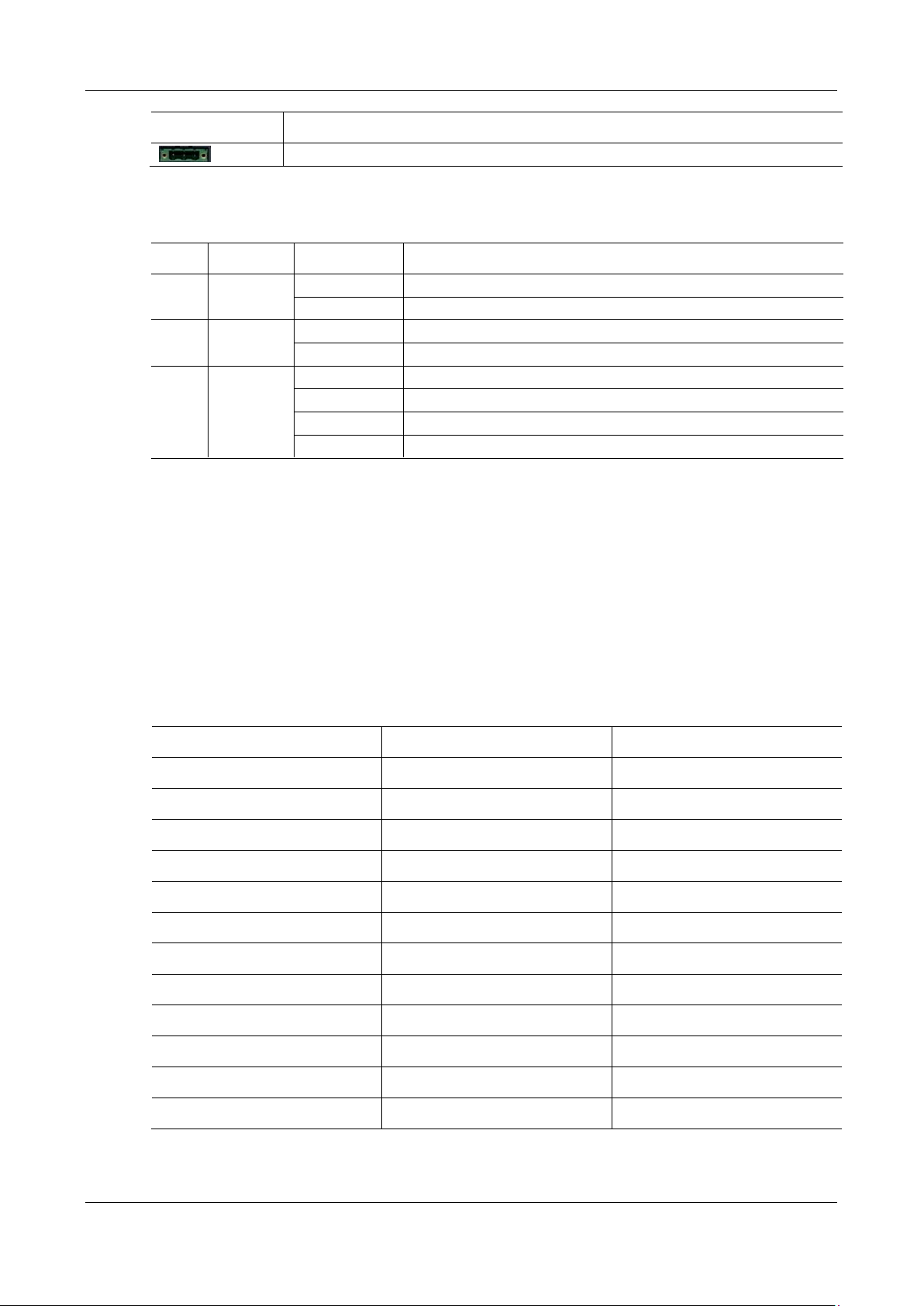
User Manual MX Series Voice Gateway
Item
Description
DC power socket,-48 VDC input.
Mark
Function
Status
Description
PWR
Power
Indication
Green
Power on
Off
Power off
STU
Status
Indication
Off
System locked and inactive
Blinking green
Normal operation
ALM
Alarm
Indication
Off
No alarms
Blinking red
New alarms occurred but not confirmed.
Steady Red
System in the process of powered up and not in the normal operation mode
Red
Alarms existed and all alarm information confirmed.
Models
Number of FXS Ports
Number of FXO Ports
MX60E-16S
16 0 MX60E-32S
32 0 MX60E-48S
48 0 MX60E-16FXO
0
16
MX60E-32FXO
0
32
MX60E-48FXO
0
48
MX60E-8S/8
8
8
MX60E-24S/8
24 8 MX60E-40S/8
40 8 MX60E-16S/16
16
16
MX60E-32S/16
32
16
MX60E-24S/24
24
24
Table 1-15 Meanings of MX60 Indicators
1.3.4 MX60E
MX60E is an upgrade product of MX60. Designed with a 1U high and 19-inch wide compact chassis,
MX60E is suitable for installation in a standard cabinet. MX60E has a built-in power module with the rating
voltage of 100-240 V AC or -48 V DC (DC is optional). Optionally, the device may use dual power supplies.
The interface card of MX60E uses a RJ-45 socket and is connected to the distribution panel in the equipment
room by using CAT-5 cables. MX60E offers up to 48 analog line ports and supports the following
configurations:
Table 1-16 Configuration Combination of MX60E
24 New Rock Technologies, Inc.
Page 25
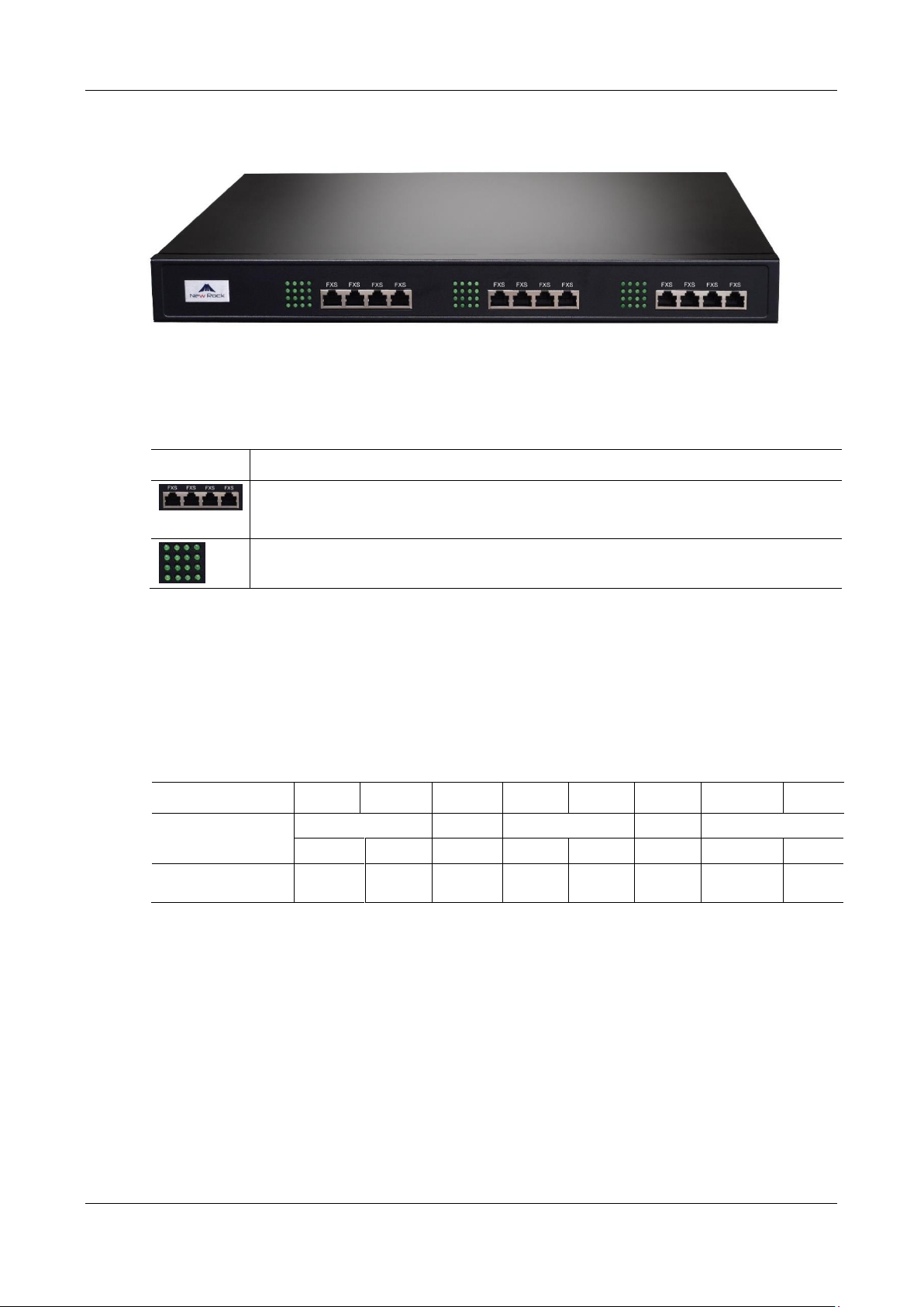
MX Series Voice Gateway User Manual
Item
Remarks
Three interface slots; each has four RJ45 sockets; each RJ45 socket can correspond with four pairs of
analog lines.
Note: Numbers of interface slots vary from different configuration.
Matrix of 4 x 4 LED status indicators on the interface card
RJ45 Pin Number
1 2 3 4 5 6 7
8
Analog line pair
1st Pair
2nd Pair
3rd Pair
2nd Pair
4th Pair
TIP1
RING1
TIP2
TIP3
RING3
RING2
TIP4
RING4
Reference color
Orange
white
Orange
Green
white
Blue
Blue
white
Green
Brown
white
Brown
Figure 1-10 MX60E Front Panel
Table 1-17 Description of MX60E Front Panel
Each RJ45 socket has 8 pins leading out 4 pairs of analog telephone or trunk lines in agreement with the
pair specifications for Ethernet interfaces, whose corresponding relations can be seen in the table below.
CAT-5 cables are used to connect the interface card and distribution panel in equipment installation.
Standard RJ11 telephone lines can be used to plug in a RJ45 socket. The telephone/trunk lines are connected
to the 3rd pair of pins for simple call test.
Table 1-18 Pin Specifications for MX60E RJ45 Socket Port
New Rock Technologies, Inc. 25
Page 26
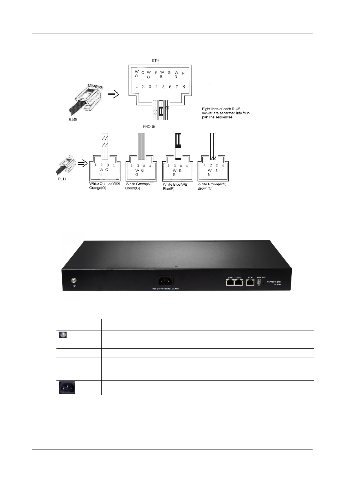
User Manual MX Series Voice Gateway
Item
Description
Ground pole
PWR/STU/ALM
Indicator, see Table 1-20 for description
USB
USB interface
CON
Configuration interface (CON), used for local management and debugging
ETH1/ETH2
Two 10/100 Mbps Ethernet ports (RJ45). They share one IP address, which by default is
192.168.2.240, and you can change it on Basic > Network page.
AC power socket, 100-240 VAC voltage input.
Figure 1-11 Schematic Diagram of MX60E Subscriber Line Connection
Figure 1-12 MX60E Back Panel-AC
Table 1-19 Description of MX60E Back Panel
26 New Rock Technologies, Inc.
Page 27

MX Series Voice Gateway User Manual
Mark
Function
Status
Description
PWR
Power
Indication
Green
Power on
Off
Power off
STU
Status
Indication
Off
System locked and inactive
Blinking green
Normal operation
ALM
Alarm
Indication
Off
No alarms
Blinking red
New alarms occurred but not confirmed.
Steady Red
System in the process of powered up and not in the normal operation mode
Red
Alarms existed and all alarm information confirmed.
Glittery Letter
Status
Blinking with C
IP address conflicts
Blinking with D
Device startup failure
Blinking with E
Network failure
Blinking with P
Software upgrading
Blinking with T
App exited (the device cannot be used normally)
Type
FXS Ports
FXO Ports
24FXS
24
0
24FXO
0
24
16FXS/8
16
8
12FXS/12
12
12
Table 1-20 Meanings of MX60E Indicators
Table 1-21 MX60E System Operation Status
1.3.5 MX120G
Designed with a 2U high and 19-inch wide compact chassis, MX120G is suitable for installation in a
standard cabinet.
The interface card of MX120G uses a RJ-45 socket and is connected to the distribution panel in equipment
room using CAT-5 cables supplied with the unit.
The device of MX120G can hold four interface cards to flexibly configure FXS and FXO ports, and each
card equips 24 ports. MX120G can provide up to 96 ports. It supports the following configurations:
Table 1-22 MX120G Interface Card
New Rock Technologies, Inc. 27
Page 28
User Manual MX Series Voice Gateway
Models
Number of FXS
Ports
Number of
FXO Ports
Concurrent calls
Description
MX120G-NA-X
Depend on the models and number of
the interface cards.
Depend on the value of X.
X=C, it is 24
X=D, it is 48
X=E, it is 72
X=F, it is 96
Single AC power
MX120G-NA-X-2AC
Dual AC power
MX120G-NA-X-1DC
Single DC power
MX120G-NA-X-2DC
Dual DC power
Item
Description
Matrix of 6x4 LED status indicator on interface card
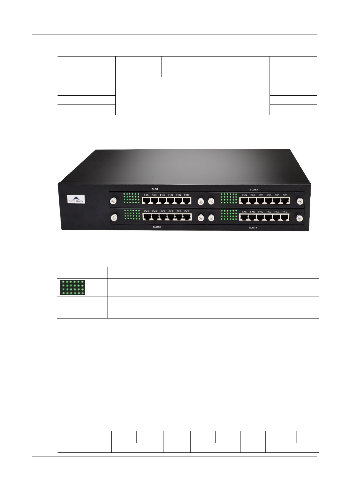
SLOT1~4
Four interface slots; each can contain one 24-port interface card.
Note: The interface card is hot swappable, but you should reboot the device after the
replacement of the interface card!
RJ45 Pin Number
1 2 3 4 5 6 7
8
Analog line pair
1st Pair
2nd Pair
3rd Pair
2nd Pair
4th Pair
Table 1-23 Configuration Combination of MX120G
Figure 1-13 MX120G Front Panel
Table 1-24 Description of MX120G Front Panel
Numbering definition of system interface slots: on the low-left side of chassis is #1 slot (marked with No.1
to 24), on the low-right side of chassis is #2 slot (marked with No.25 to 48), on the up-left side of chassis
is #3 slot (marked with No.49 to 72), and on the up-right side of chassis is #4 slot (marked with No.73 to
96).
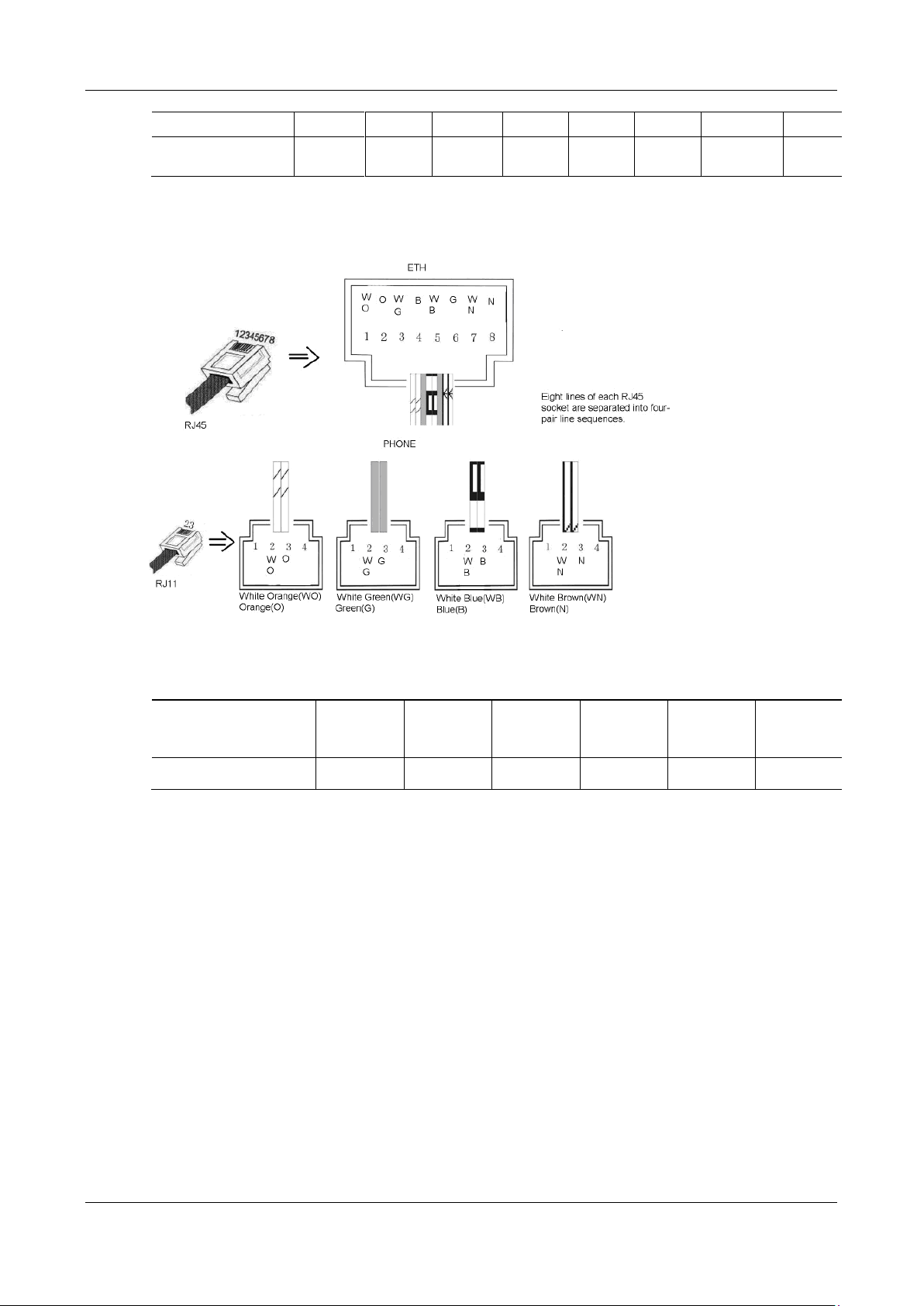
Each RJ45 socket has 8 pins leading out 4 pairs of analog telephone or trunk lines in agreement with the
pair specifications for Ethernet interfaces, whose corresponding relations can be seen in the table below.
CAT-5 cables are used to connect the interface card and distribution panel in equipment installation.
Standard RJ11 telephone lines can be used to plug in a RJ45 socket. The telephone/trunk lines are connected
to the 3rd pair of pins for simple call test.
Table 1-25 Pin Specifications for MX120G RJ45 Socket Port
28 New Rock Technologies, Inc.
Page 29
MX Series Voice Gateway User Manual
TIP1
RING1
TIP2
TIP3
RING3
RING2
TIP4
RING4
Reference color
Orange
white
Orange
Green
white
Blue
Blue
white
Green
Brown
white
Brown
RJ45 Socket No.
(From Left to Right)
1 2 3 4 5
6
Line No. of This Card
1 4
5 8
9 12
13 16
17 20
21 24
Figure 1-14 Schematic Diagram of MX120G Subscriber Line Connection
Table 1-26 Corresponding Relation Between MX120G RJ45 Socket and Line Number
There is a 6 × 4 LED indicator matrixes on the left side of interface board. Each row of LED indicator
matrixes matches four telephone lines on a RJ45. The first row on the left matches Line 1-4 respectively
from top to bottom, the first row on the right matches Line 21-24 respectively from top to bottom, and the
middle rows in the same manner.
LED indicators are used for multiple purposes as follows:
Line status indication: this is the most common mode during normal use of equipment. In this mode, if
a line is idle, the indicator corresponding to it goes off; if a line is in call or in use status (such as ringing,
offhook) the indicator corresponding to it goes on.
Line type indication: this is the mode for cable wiring check when installing the equipment. This mode
can be entered by disconnecting Ethernet cables (Both WAN and LAN ports must be disconnected) at
installation stage. After entering this mode, steady on LED indicates that the corresponding line is
equipped as analog subscriber line type, blinking LED indicates that the corresponding line is equipped
as analog trunk line type, off LED indicates that the corresponding line is not equipped or not ready for
use.
New Rock Technologies, Inc. 29
System operation status indication: this is the mode for displaying information on system operation of
equipment in specific conditions. Usually, this mode is entered when some prompts are required to give
Page 30
User Manual MX Series Voice Gateway
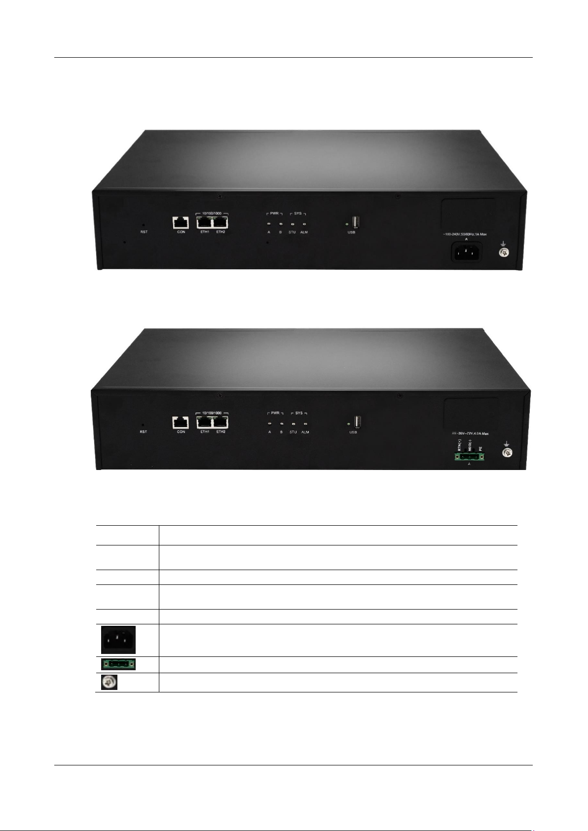
Item
Description
RST
To restore the device to factory default, press the RST for more than 3 seconds and release it
when the STU light starts blinking in red. This setting will be valid after rebooting the device.
CON
Configuration interface (CON), used for local management and debugging.
ETH1/ETH2
Two 10/100 Mbps Ethernet ports (RJ45). They share one IP address, which by default is
192.168.2.240 and you can change it on Basic > Network page.
USB
USB interface
AC power socket, 100-240 VAC voltage input.
DC power socket,-48 VDC input.
Ground Pole
operator during equipment startup, diagnosis or operation. In this mode, LED flashes to display numbers,
letters or other patterns in matrix. Please refer to Table 1-29.
Figure 1-15 MX120G Back Panel-AC
Figure 1-16 MX120G Back Panel-DC
Table 1-27 MX120G Back Panel
30 New Rock Technologies, Inc.
Page 31

MX Series Voice Gateway User Manual
Indicator
Status
Description
PWR
(red, green)
Steady green
The power supply is working.
Off
No power supply.
Steady red
The power supply is abnormal.
STU
(red, green)
Blinking green
The device is running.
Steady red
The device is starting.
Blinking red
The device is under diagnosis.
Off
The device is locked.
ALM
(red, green)
Off
No alarm
Blinking red
The alarms indicated by the blinking alphabetic messages C/E/T on LED dotmatrix are generated.
Steady red
The alarms indicated by the blinking alphabetic messages D on LED dotmatrix are generated.
ETH1/ETH2
(green)
Steady green
(right side)
The transmission rate is 1000 Mbps.
Off
(right side)
The transmission rate is 10/100 Mbps.
Steady green
(left side)
A physical connection is established without any traffic.
Blinking green
(left side)
A physical connection is established with traffic.
Off
(left side)
No connection is established.
USB
(green)
Steady green
The USB device is detected.
Off
The USB device is not detected.
Glittery letter
Status meaning
Blinking with C
IP address conflicts
Blinking with D
The severe starting failure needs to address by your dealer
Blinking with E
Network failure
Blinking with P
Software upgrading
Blinking with T
App exited (The device cannot be used normally)
Table 1-28 Meanings of MX120G Indicators
Table 1-29 MX120GSystem Operation State
New Rock Technologies, Inc. 31
Page 32
MX Series Voice Gateway User Manual
Name
Description
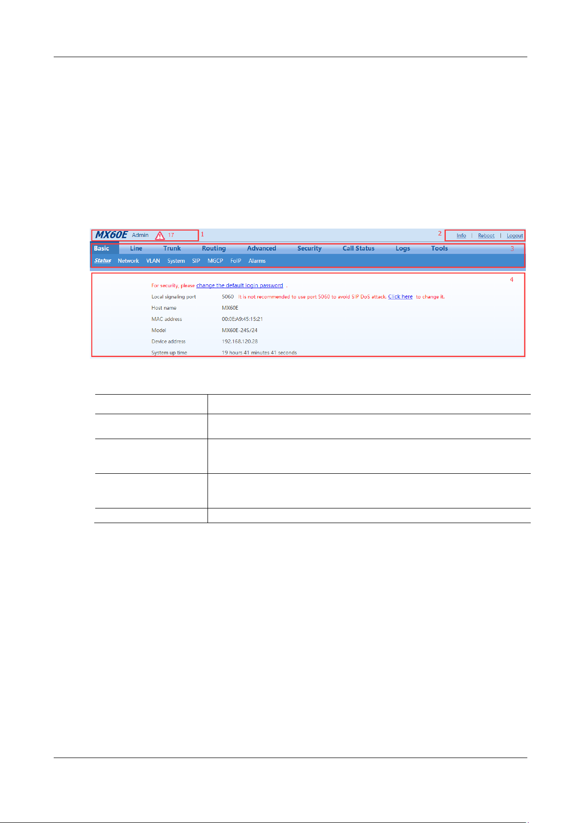
1. General information
display bar
Displays the device name, login identity, current quality of alarms, and time
synchronization status.
2. General operation bar
Provides access to product information, comments, device restart, and exit, and provides
a search box for searching for a corresponding configuration page according to a
function name.
3. Menu bar
Includes a two-level menu structure. When the cursor is moved to an upper-level menu,
the lower-level menu is displayed for your selection. After you click a tab, the tab page
is displayed in the configuration area.
4. Configuration area
Allows you to modify and view configurations.
1.4 Web Management Page
1.4.1 Layout
The Web GUI of the MX series gateways includes a general information display bar, a general operation
bar, a menu bar, and a configuration area.
Figure 1-17 Web GUI
Table 1-30 Web GUI Layout Description
1.4.2 Buttons Used on Gateway Management Interface
A save button is at the bottom of each configuration interface. It is used to submit configuration
information. Users should click the Save button after the completion of parameter configuration on a
page. A success prompt will appear if configuration information is accepted by the system; if The
configuration takes effect after the system is restarted dialog box appears, it means that the parameters
are valid only after a system restart. It is recommended that users press the Reboot button on the top right
corner to enable the configuration after changing all parameters to be modified.
New Rock Technologies, Inc. 32
Page 33

MX Series Voice Gateway User Manual
Type
Default DHCP Service
Default IP Address
Default Subnet Mask
MX8A
Enabled
192.168.2.218
255.255.0.0
HX4E
Enabled
192.168.2.218
255.255.0.0
MX60
Disabled
192.168.2.240
255.255.0.0
MX60E
Disabled
192.168.2.240
255.255.0.0
MX120G
Disabled
192.168.2.240
255.255.0.0
2 Parameters Setting
2.1 Login
2.1.1 Obtaining Gateway IP Address
MX8A/HX4E Gateways start DHCP service by default, and automatically obtain an IP address on the
LAN; you can use the factory-default gateway IP address if it is unable to be obtained (e.g. when
connected directly with a computer).
By default, the MX60/MX60E/MX120G uses a static IP address.
To change the fixed IP address, you can use a telephone connected to the FXS port and dial *90+the
fixed IP address+#subnet mask#IP address of the gateway#0#. The dots "." in the IP address need to
be replaced with star keys "*".
To obtain an IP address through DHCP, you can use a telephone connecting to the FXS port and dial
*90###1#.After "The feature is now activated" is heard, restart the device.
Table 2-1 Default IP Address of Gateway
You can dial ## to obtain the current gateway IP address, version information of firmware and port
used to access the Web GUI using the telephone connected to the subscriber line (FXS ports) after the
equipment is powered on.
If the device does not have FXS ports (such as an MX8A-8FXO or HX440E), you can use New
Rock's device IP address obtaining tool called "Finder" to obtain the IP address.
You can download the "Finder" software on http://www.newrocktech.com
A user could fail to log in with the default IP address if the IP address of user’s computer and the default
gateway IP address are not at the same network segment. Set the IP address of user's computer to be
identical with the same network segment of the gateway. For example, if the gateway IP address is
192.168.2.218, set the computer’s IP address to any address at the network segment of 192.168.2.XXX.
2.1.2 Logging On to Web GUI
Enter the gateway IP address and verification code (case-insensitive) in the browser address bar (e.g.
192.168.2.218). You can enter the gateway configuration login interface by entering a password on the
New Rock Technologies, Inc. 33
Page 34
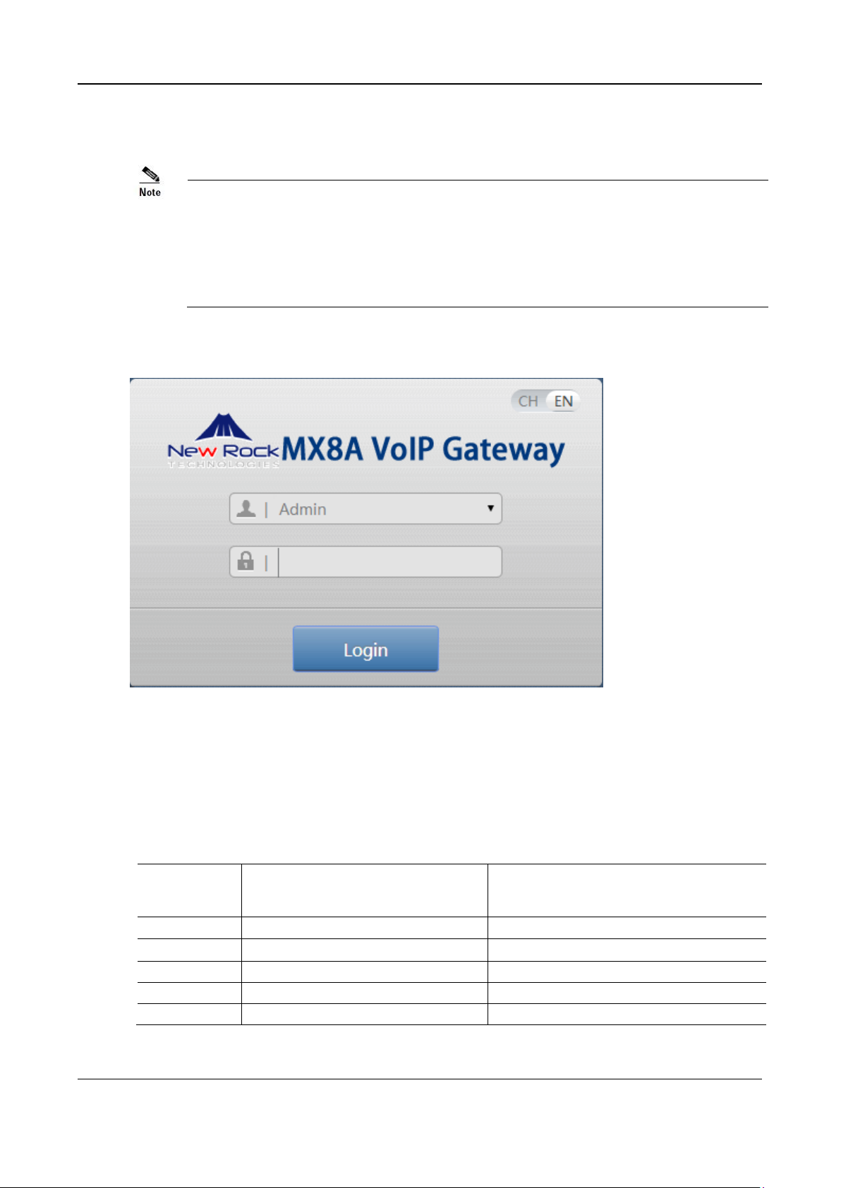
User Manual MX Series Voice Gateway
The Web GUI can be accessed using browsers such as Internet Explorer 8 to 11, Firefox,
and Google Chrome. The IE browser is used as an example below.
The device is only allowed to access using HTTPS. Since the factory default certificate is
used a prompt like "There is a problem with this website's security certificate" may
occur. Click Continue to this website to access the login page.
Type
Default Administrator Passwords
(lowercase letters required)
Default Operator Password
MX8A
mx8
operator
HX4E
hx4
operator
MX60
mx60
operator
MX60E
mx60
operator
MX120G
mx120
operator
login interface. Both Chinese and English are provided for the Web GUI.
Figure 2-18 Login Interface for MX8A Gateway Configuration
2.1.3 Gateway Administrator and Operator Rights (Web GUI)
Login users are classified into administrator and operator. The default password is shown in Table 2-2.
The password is shown in a cipher for safety.
Table 2-2 Default Passwords for logging to Web GUI
34 New Rock Technologies, Inc.
The administrator is allowed to browse and modify any configuration parameter and modify login
Page 35
MX Series Voice Gateway User Manual
The system will confirm timeout if users do not conduct any operation within 10 minutes
after login. They are required to log in again for continuing operations.
Upon completion of configuration, click the Logout button to return to the login page, so
as not to affect the login permission of other users.
To ensure system security, please choose Tools>Change password and change the
password when you log in for the first time. For details, see 2.7.1 Access Security.
Disable SSH in time after use.
To change the SSH access port, go to Security > Access page. For details, see 2.7.1 Access Security.
passwords. After login, "Admin” is displayed on the upper left corner of the interface.
The operator is allowed to browse a subset of the configuration parameters. After login, "Operator” is
displayed on the upper left corner of the interface.
The following pages are not allowed to browse:
Advanced>Security
System tool>Change password
System tool>Software upgrade
System tool>Import data
System tool>Export data
The gateways allow multiple users to log in if needed.
When multiple administrators log in, the first can modify, while others (displayed as Viewer) may only
browse.
2.1.4 Accessing Through SSH
For safety, users are not allowed to directly access the SSH as the root user.
Follow the steps below to access a device through SSH:
Step 1
Step 2
Enable SSH on
Log in as the
operator
Security>Access
user enter the password (
page.
Operator@021
by default).
Step 3
Run
su root
to switch to the
user. Enter the password (
root
voipgateway
user.
New Rock Technologies, Inc. 35
by default) of the
root
Page 36
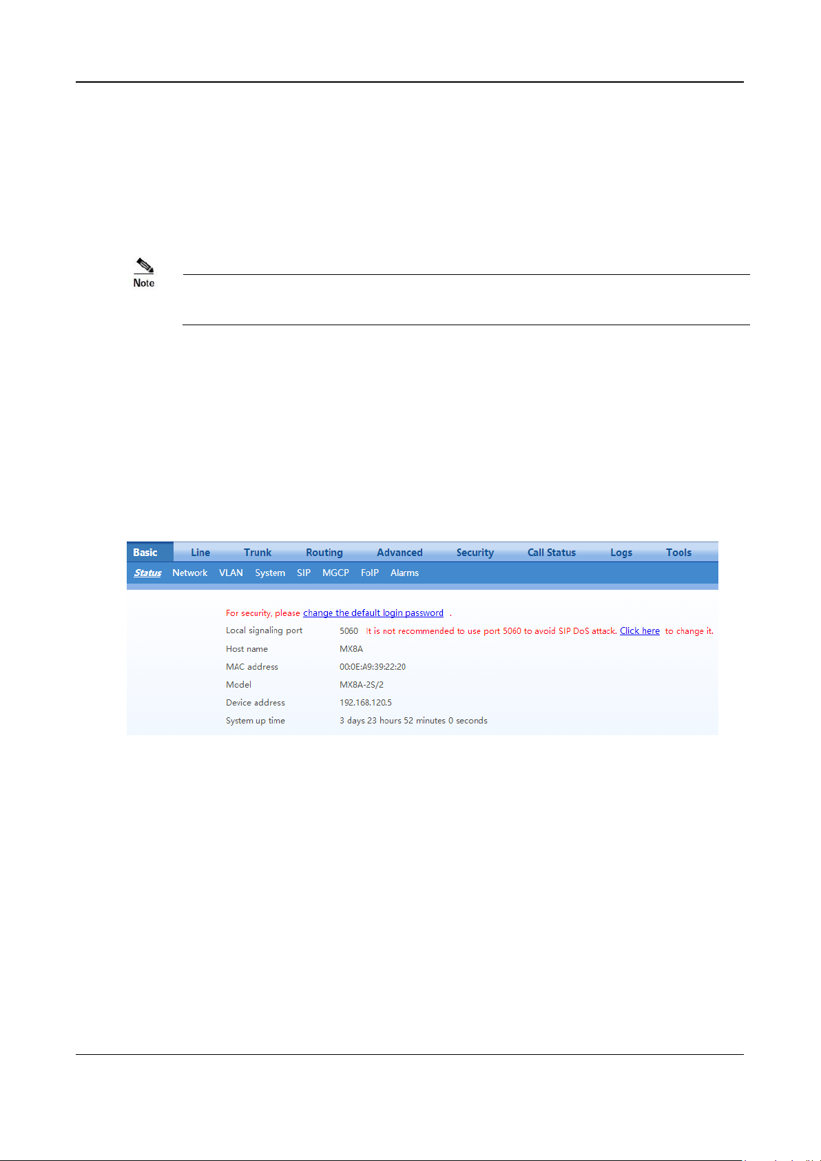
User Manual MX Series Voice Gateway
You need to periodically change the passwords for the operator and root users.
To change the passwords, go to Security > Access list page. For details, see 2.7.1 Access Security.
2.1.5 SSH user Permissions
Both root user and the operator user are allowed to access a device with SSH:
root user has permission to change the configuration of all parameters.
operator user has permission to access only the directories of the user. It is allowed to use su- commands
only.
2.2 Basic Configuration
2.2.1 Status
After login, open the Basic tab page to view device information. If the SIP port of the device is 5060, you
are advised to modify it.
Figure 2-19 Status Interface
2.2.2 Network
After login, click Basic>Network to open the configuration interface.
36 New Rock Technologies, Inc.
Page 37
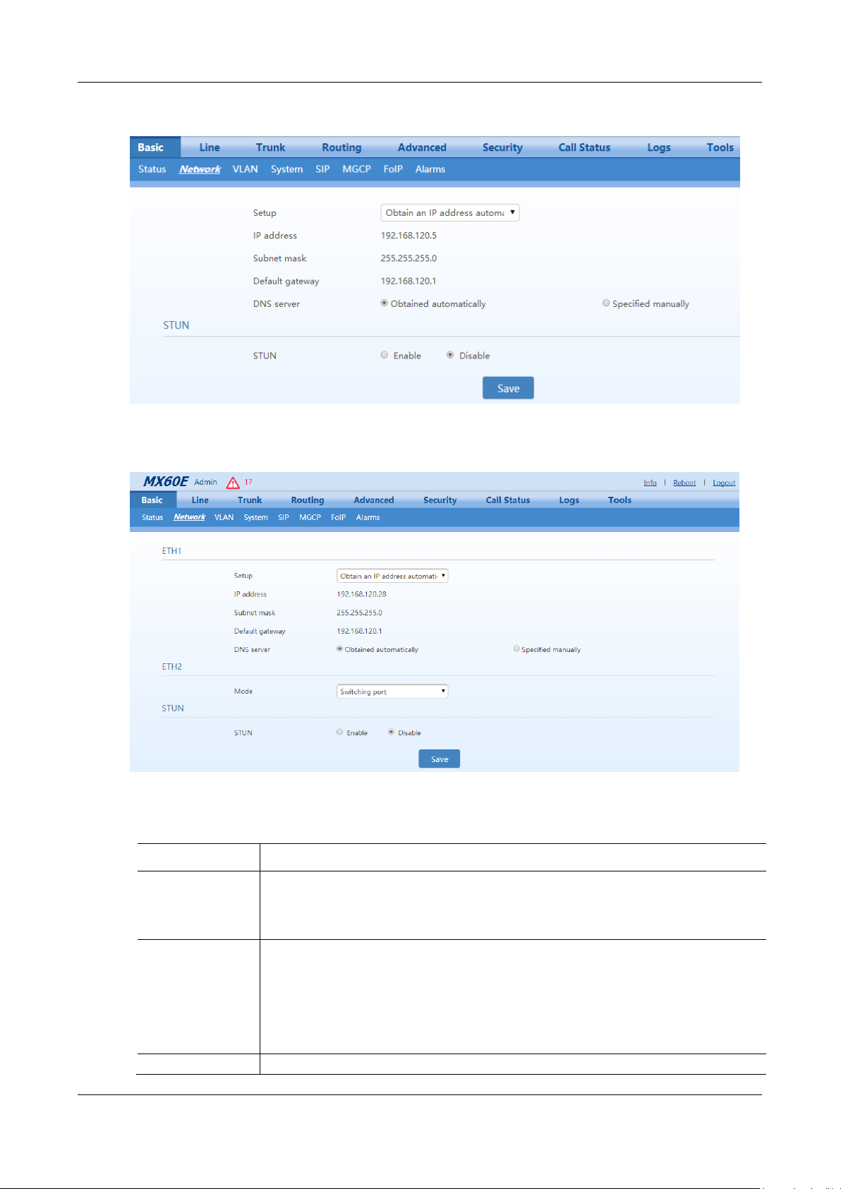
MX Series Voice Gateway User Manual
Name
Description
ETH1
(MX60/MX60E/MX
120G)
ETH1 configurations.
MX60, MX60E, and MX120G each have two network ports: ETH1 and ETH2.
HX4E and MX8A each have only one network port.
Setup
Methods for obtaining an IP address.
Static IP address: static IP address is used;
Obtain an IP address automatically: use the dynamic host configuration protocol (DHCP) to
obtain IP addresses and other network parameters;
PPPoE: PPPoE service is used.
Username
Enter an authentication user name if PPPoE service is selected, and there is no default value.
Figure 2-20 Network Configuration Interface (HX4E/MX8A)
Figure 2-21 Network Configuration Interface (MX60/MX60E/MX120G)
Table 2-3 Network Configuration Parameters
New Rock Technologies, Inc. 37
Page 38

User Manual MX Series Voice Gateway
Name
Description
Password
Enter an authentication password if PPPoE service is selected, and there is no default value.
IP address
If “Static IP” or “DHCP” is selected but an address fails to be obtained, the gateways will use
the IP address filled in here. If the gateways obtain an IP address through DHCP, the system
will display the current IP address automatically obtained from DHCP.
Subnet mask
The subnet mask is used with an IP address. When the gateway uses a static IP address, this
parameter must be entered; when an IP address is automatically obtained through DHCP, the
system will display the subnet mask automatically obtained by DHCP. It has no default value.
Default gateway
The IP address of LAN gateway. When the gateway obtains an IP address through DHCP, the
system will display the LAN gateway address automatically obtained through DHCP. It has no
default value.
DNS server
Obtained automatically: When the connection mode is "DHCP" or "PPPoE", the device uses the
automatically obtained IP address of the DNS server.
Specified manually: Use the DNS server addresses specified manually.
Primary DNS Server
If Specified manually is selected, the network IP address of the Primary DNS server must be
entered, there is no default value.
Secondary DNS
Server
If Specified manually is selected, the network IP address of the Secondary DNS server can be
entered, there is no default value.
ETH2
(MX60/MX60E/
MX120G)
ETH2 configurations
Mode
Switching port: ETH1 and ETH2 are switch ports. The two ports share the IP address
of ETH1 on the Web GUI.
Redundant port for ETH1: The port ETH2 is the redundant port for port ETH1. In
this mode, both ETH1 and ETH2 are connected to the same LAN or WAN, if ETH1
is damaged or offline, ETH2 automatically connects the network.
STUN
The device periodically sends a STUN request to the STUN server to obtain the public IP
address for the front-end router.
It is disabled by default.
Server IP address /
Name
Set the IP address or domain name of the STUN server. The factory default STUN server is the
New Rock STUN server.
Server port
Set the port of STUN server. It is 3478 by default.
Session interval
The interval at which the device sends a STUN request ranges from 30 to 3600 seconds. It is 60
second by default.
Operations
Trunk re-registration: A re-registration of the SIP trunk is triggered upon the detection of
the change of the public IP address of the device by using STUN query. Normally, the session
interval of STUN request should be shorter than the registration period.
Note: The IP address obtained through STUN is used only for re-registration of SIP server,
and it is not used in SIP message fields such as Via and Contact and SDP C field.
Trunk re-registration & NAT address updating: A re-registration of the SIP trunk is
triggered upon the detection of the change of the public IP address of the device by using
STUN query. The IP address obtained through STUN is used in SIP message fields such as
Via and Contact and SDP C field.
2.2.3 VLAN
38 New Rock Technologies, Inc.
After login, click Basic>VLAN to open the configuration interface.
Page 39
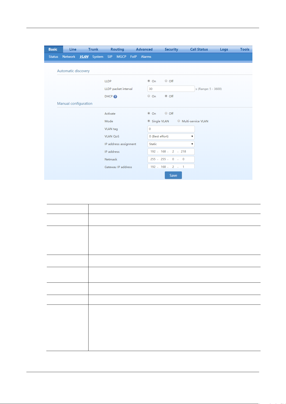
MX Series Voice Gateway User Manual
Name
Description
Automatic
discovery
LLDP
On: Indicates that the LLDP is enabled. The device periodically sends LLDP messages and
parses received LLDP messages to get VLAN ID and priority.
Off (default value): Indicates that the LLDP is disabled. The device does not send any LLDP
messages, nor parses any received LLDP messages.
LLDP Packet
interval
This parameter specifies the interval at which LLDP messages are sent after the LLDP is
enabled. The value range is 5 to 3600 seconds. The default value is 30 seconds.
DHCP
Enable the device to obtain the VLAN tag and QoS by using DHCP option 132 and option 133.
Note: This function works only when DHCP is selected on Basic>Network page.
Manual
configuration
Activate
Enable/disable VLAN.
Mode
Select the VLAN mode:
Single VLAN: All services of the device are on the same VLAN, and the device receives
only data packets carrying the VLAN and includes the VLAN tag in all sent data packets.
Multi-service VLAN: The device can configure different VLAN information for the voice
service (SIP signaling and RTP/T.38 media stream) and the management service
(HTTP/HTTPS, Telnet) and includes a different VLAN tag in a data packet of a different
service.
Figure 2-22 VLAN Configuration Interface
Table 2-4 VLAN Configuration Parameters
New Rock Technologies, Inc. 39
Page 40
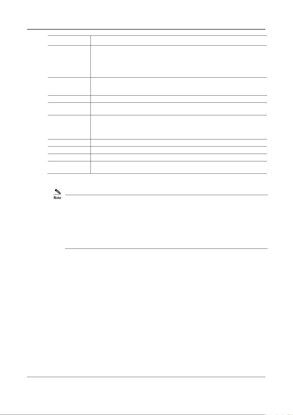
User Manual MX Series Voice Gateway
Name
Description
Voice VLAN
VLAN to which the voice service (SIP signaling and RTP/T.38 media stream) belongs.
None: disable the voice VLAN
Mode 1: SIP and RTP/T.38 are on the same VLAN
Mode 2: SIP and RTP/T.38 are on different VLANs
Management VLAN
Selected: enable the management VLAN
Deselected: disable the management VLAN
VLAN tag
Tag of the VLAN. The value ranges from 3 to 4093.
VLAN QoS
Priority of the VLAN. The value ranges from 0 to 7. A larger value indicates a higher priority of
a to-be-sent data packet.
IP address
assignment
Type for obtaining the IP address of the VLAN interface.
Static: set the IP address to a static IP address
DHCP: automatically obtain an IP address by using the DHCP protocol
IP address
IP address of the VLAN interface
Netmask
Subnet mask of the VLAN interface
Gateway IP address
IP address of the gateway of the VLAN interface
MTU
Maximum Transmission Unit value of the VLAN interface. The value ranges from 576 to 1500.
The default value is 1500.
A reboot is required to enable the VLAN configuration.
After a VLAN is configured, only PCs in the same VLAN can access the device.
The device address used to log in to the Web GUI can be obtained by connecting a
phone to an FXS port of the device, and dialing ##. In the case of a single VLAN, the IP
address of the single VLAN is voiced; in the case of a multi-service VLAN, the IP address
of the management VLAN is voiced.
2.2.4 System
After login, click Basic>System to open the configuration interface.
40 New Rock Technologies, Inc.
Page 41
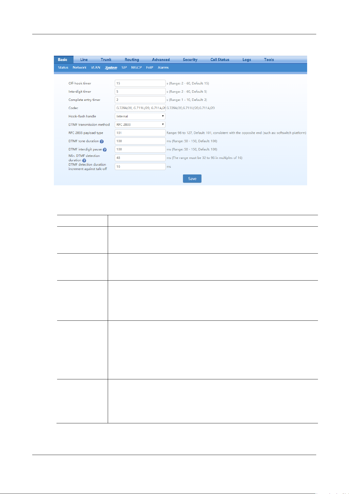
MX Series Voice Gateway User Manual
Name
Description
Off-hook timer
If a subscriber does not dial any digit within the specified time by this parameter after off-hook,
the gateways will prompt to hang up with a busy tone.
The value must be an integer, decimal points are not allowed.
Unit: Seconds; Default value: 15 seconds.
Interdigit timer
The maximum time interval to dial the next digit.
After timeout, the gateways will call out with the collected number.
The value must be an integer, decimal points are not allowed.
Unit: Seconds; Default value: 5 seconds.
Complete entry
timer
The value must be an integer, decimal points are not allowed.
Unit: Seconds; Default value: 2 seconds.
This parameter is used with the "x.T" rule set in dialing rules. For example, there is "021.T" in
the dialing rules table. When a subscriber has dialed 021 and has not dialed the next number
within a set time by this parameter (e.g. 2 seconds), the gateways will consider that the
subscriber has ended dial-up and call out the dialed number 021.
Codec
Configures the voice codec in the format of "codec/frame size", for example, G.729A/20. For
the available codec types and frame size, see Table 2-6. When multiple types of codec are
configured, the codec is separated by using a comma (,). The device negotiates with the
registration platform on the use of codec in left-to-right order.
Note: The default frame size for each codec is displayed on the page, you can specify a proper
value according to the actual configuration environment. If the frame size is not specified, the
default one will be used. For example, if the codec is set to G.729A, the device automatically
use G.729A/20 to negotiate with the registration platform.
Hook-flash handle
The gateways provide the following processing modes after detecting hook flash from
subscriber terminals:
Internal: the hook flash event will be handled internally;
Server(RFC 2833): transmitting the hook flash to platform with RFC 2833;
Server (SIP INFO): transmitting the flash-off to platform with SIP INFO.
Figure 2-23 System Configuration Interface
Table 2-5 System Configuration Parameters
New Rock Technologies, Inc. 41
Page 42

User Manual MX Series Voice Gateway
Name
Description
DTMF transmission
method
Transmission modes of DTMF signal supported by the gateways include RFC 2833, Audio and
SIP INFO. The factory default value is RFC 2833.
RFC 2833: separate DTMF signal from sessions and transmit it to the platform through
RTP data package in the format of RFC2833;
Audio: transmit DTMF signal to the platform with sessions;
SIP INFO: separate DTMF signal from sessions and transmits it to the platform in the form
of SIP INFO messages.
RFC2833+SIP INFO: send DTMF signals simultaneously via RFC 2833 and SIP INFO.
RFC 2833 payload
type
Used with "RFC 2833" in the DTMF transmission modes. The default value of 2833 payload
type is 101. The effective range available: 96 ~ 127. This parameter should match the setting of
far-end device (e.g. platform).
DTMF tone duration
This parameter sets the on time (in ms) of DTMF signal sent from FXO port.
The default value is 100 ms. The duration time range is 50 ~ 150 ms.
DTMF interdigit
pause
This parameter sets the off time (ms) of DTMF signal sent from port. The default value is 100
ms. The duration time range is 50 ~ 150 ms.
Min. DTMF
detection duration
Minimum duration time of effective DTMF signal. Its effective range is 32 to 96 ms. The
default value is 48 ms. The greater the value is set, the more stringent the detection.
DTMF detection
duration increment
against talk-off
An actual detection threshold is determined by combining the Min. DTMF detection duration
and this parameter.
Actual detection threshold = Min. DTMF detection duration + DTMF detection duration
increment against talk-off.
The valid values are 16, 32, and 48 in million seconds. Increase the value can prevent false
detection of DTMF signal.
Codec
Supported Devices
Bit Rate (kbit/s)
Frame size (ms)
G.729A
HX4E/MX8A/MX60/MX60E/MX120G
8
10/20 (default value)/30/40
G.711U/G.711A
HX4E/MX8A/MX60/MX60E/MX120G
64
10/20 (default value)/30/40
G.723
MX60/MX60E/MX120G
5.3/6.3
30 (default value)/60
iLBC
MX60/MX60E/MX120G
13.3/15.2
20/30 (default value)
GSM
MX60/MX60E/MX120G
13
20
Table 2-6 Codec Methods Supported by Gateways
2.2.5 SIP
After login, click Basic>SIP to open the configuration interface.
42 New Rock Technologies, Inc.
Page 43
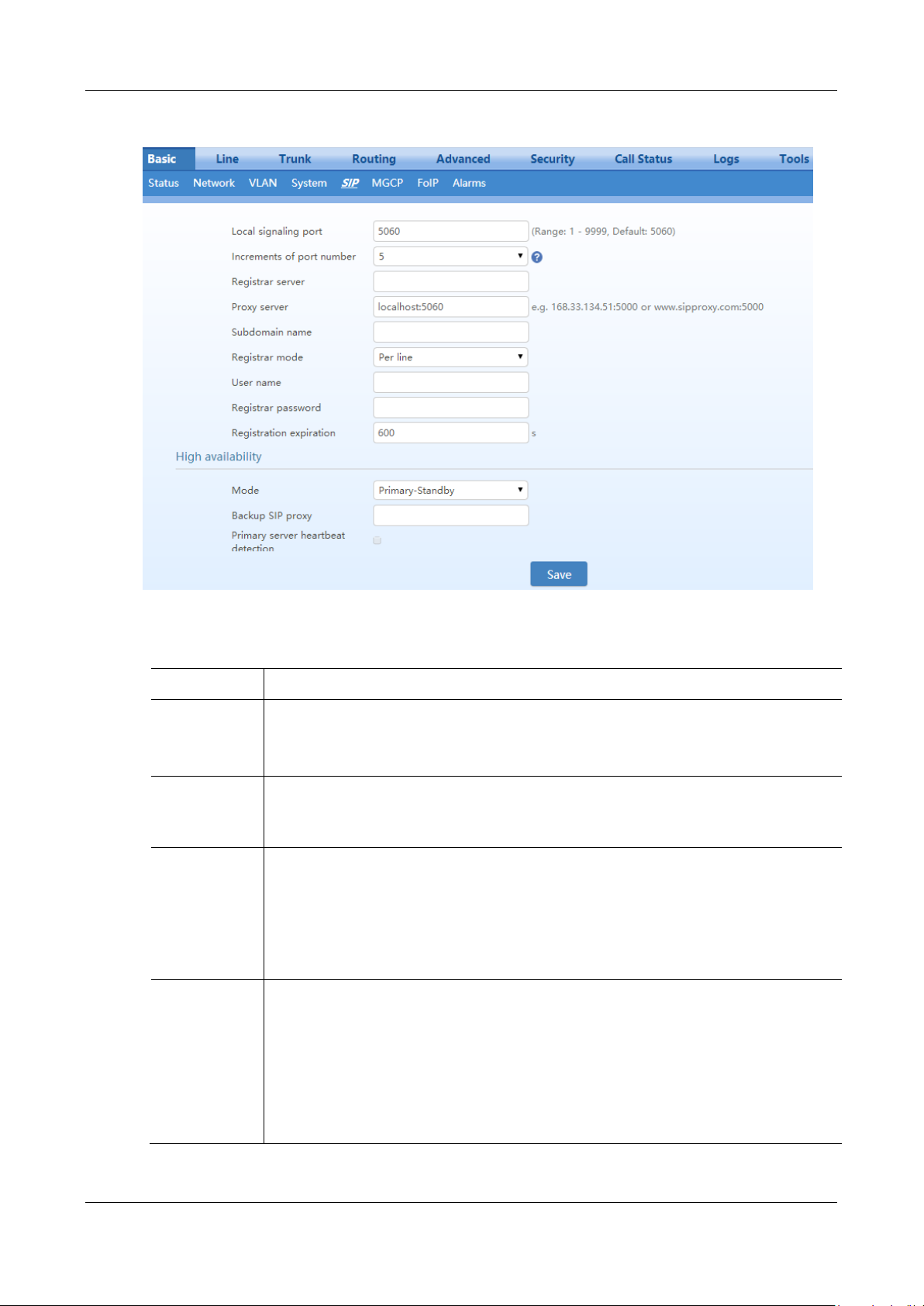
MX Series Voice Gateway User Manual
Name
Description
Local signaling
port
Configure the UDP port for transmitting and receiving SIP messages, with its default value 5060.
Note: The signaling port number can be set in the range of 1-9999, but cannot conflict with the
other port numbers used by the equipment.
Increments of
port number
If "n" (ranked from 1-10) is chosen, after the failure registration of signaling port’s original
configuration, the variation of signaling port’s change ranges from the original signaling port to the
original signaling port +n". Register with the new signaling port value (signaling port +1) until it
succeeds.
Registrar server
Configure the address and port number of the SIP registration server. The address and port number
are separated by “:”. It has no default value.
The register server address can be an IP address or a domain name.
e.g. 168.33.134.51:5000 or www.sipproxy.com:5000.
When a domain name is used, you must activate DNS service and configure DNS server parameters
on the network-configuration page.
Proxy server
Configure the IP address and port number of the SIP proxy server. The address and port number are
separated by “:”. It has no default value.
The proxy server address can be set to an IP address or a domain name.
e.g. 168.33.134.51:5000 or www.sipproxy.com:5000.
When a domain name is used, you must activate DNS service and configure DNS server parameters
on the network-configuration page.
When a domain name is used, you can fill in a backup IP address in Backup SIP proxy server in
the High Availability configuration. This allows the device to failover to the IP address if the
domain name resolution service fails.
Figure 2-24 SIP Configuration Interface
Table 2-7 SIP Configuration Parameters
New Rock Technologies, Inc. 43
Page 44
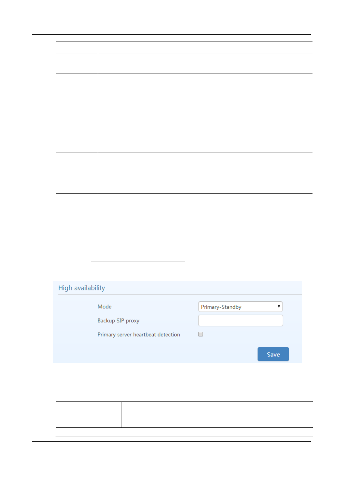
User Manual MX Series Voice Gateway
Name
Description
Subdomain
name
This domain name will be used in INVITE messages. If it is not set here, the gateways will use the
IP address or domain name of the proxy server as the user-agent domain name. It has no default
value.
Registrar mode
The gateway supports three registration schemes:
Per line (default): authenticate and register per line.
Per gateway: authenticate and register per gateway.
Per line/GW auth: Enable registration per line. Use the number configuration per line. Use the
global account and password in authentication.
User name
Configure the user name as part of the account for registration. It has no default value.
Note: If Per gateway or Per line/GW Auth is selected for Registrar mode, the user name must be
entered here. If per line is selected the user name should be set on “Line> Feature” page (Refer to
2.3.2 Subscriber Line Features).
Registrar
password
Password as part of account information is used for authentication by platform. It has no default
value. It can be formed with either numbers or characters, and is case sensitive.
Note: If Per gateway or Per Line/GW Auth is selected for Registrar mode, the password must be
entered here. If Per line is selected the password should be set on “Line>Feature” page (Refer to
2.3.2 Subscriber Line Features).
Registration
expiration
Valid time of SIP re-registration in seconds. Its default value is 600.
Name
Description
Mode
High availability can be configured as Primary-Standby, Active-Standby or Load
Balancing mode.
Primary-Standby mode
2.2.6 High Availability
After login, click Basic>SIP to open the configuration interface.
For details, see High Availability Configuration Guide.
Figure 2-25 High Availability Configuration Interface
Table 2-8 Parameters
44 New Rock Technologies, Inc.
Page 45
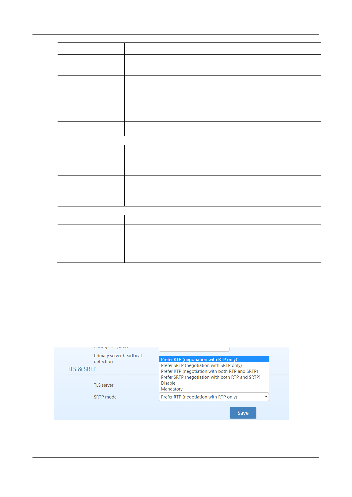
MX Series Voice Gateway User Manual
Name
Description
Backup SIP proxy
Configure the address and port number of the backup SIP proxy server. When the
primary SIP server fails, the gateway failovers from the primary server to the backup
server automatically.
Primary server heartbeat
detection
Select it to send OPTIONS request to the primary SIP server all the time.
If the gateway does not receive any response to OPTIONS request, it failovers to the
backup server.
After failover to the backup server, the gateway will still send OPTIONS to the primary
server. It switches back to the primary server once the response to the OPTIONS request
is received.
OPTIONS request period
The interval between receiving the response (200) from the SIP server to the previous
OPTIONS and sending the next OPTIONS.
Active-Standby mode
SIP proxy server setting
A maximum of five servers can be added.
OPTIONS Keep-alive
Enable: send OPTIONS request to the current SIP server.
Disable: OPTIONS request is not sent to the current SIP server.
Active SIP server
This parameter displays the current SIP server address.
Switchover
If you click Switchover, the gateway performs switchover to the next available server in
sequence based on the SIP server list.
Load Balancing mode
SIP proxy server setting
A maximum of five SIP servers can be added.
OPTIONS request period
The interval between receiving the response (200) from the SIP server to the previous
OPTIONS and sending the next OPTIONS.
OPTIONS request timeout
The period since the sending of the last OPTIONS with no response by the SIP server.
REGISTER request timeout
The period of time from the sending of the first REGISTER with no response by the
previous SIP server to the sending of REGISTER to the next SIP server.
2.2.7 TLS&SRTP
The MX series gateways support SIP signaling over TLS and SRTP (an encrypted form of RTP) as well. .
After login, choose Basic > SIP, to go to the configuration page.
Figure 2-26 TLS&SRTP Configuration Interface
New Rock Technologies, Inc. 45
Page 46
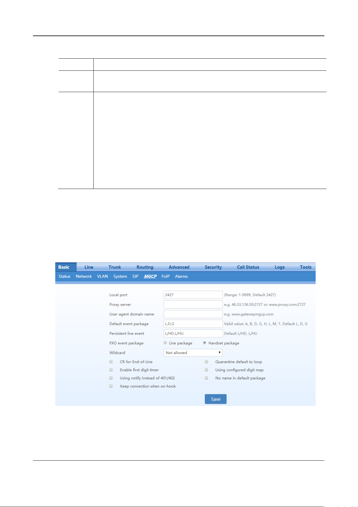
User Manual MX Series Voice Gateway
Name
Description
TLS server
Set to the address of a softswitch or IMS platform that supports TLS. After the configuration, the TLS
function is automatically enabled but you should enable TLS on Line > Configuration or Trunk >
Configuration page to apply it.
SRTP mode
Set to one of the following negotiation modes:
RTP only (fallback to SRTP for incoming calls): only RTP negotiation is used for outgoing calls,
but SRTP negotiation is also supported for incoming calls.
SRTP only (fallback to RTP for incoming calls): only SRTP negotiation is used for outgoing calls,
but RTP negotiation is also supported for incoming calls.
Both RTP&SRTP (RTP preferred for incoming calls): both RTP and SRTP negotiations are
supported for outgoing calls, RTP negotiation is preferred for incoming calls.
Both RTP&SRTP (SRTP preferred for incoming calls): both RTP and SRTP negotiation are
supported for outgoing calls, SRTP negotiation is preferred for incoming calls.
Disable: Disable SRTP, support only RTP
Mandatory: SRTP
Table 2-9 TLS&SRTP Configuration Parameter
2.2.8 MGCP
The gateways use SIP protocol by default. When the gateways need to interface with MGCP protocol based softswitch platform, set the relevant parameters here.
After login, click Basic > MGCP to open the configuration interface.
Figure 2-27 MGCP Configuration Interface
46 New Rock Technologies, Inc.
Page 47

MX Series Voice Gateway User Manual
Name
Description
Local port
Configure the UDP port for transmitting and receiving MGCP messages, the default
value is 2427.
Note: The signaling port number can be set in the range of 1-9999, but cannot conflict
with the other port numbers used by the equipment.
Proxy server
Configure the IP address and port number of MGCP proxy server, separated by “:”. It
has no default value.
The address can be set to an IP address or a domain name according to the subscribers’
requirements. When a domain name is used, it is required to configure DNS server on
the "Basic>Network" page. Examples of complete and effective configuration:
46.33.136.50:2727 or www.proxy.com: 2727.
User agent domain name
The domain name associated with the call agent, it has no default value. DNS server is
required to set.
Example: www.gatewaymgcp.com.
Default event package
List all the types of default event packages supported by the HX4. Multiple package
names are separated by“,”.
The default value is L, D, G
L: Line Package
D: DTMF Package
G: Generic Media Package
Persistent line event
List the event types that the gateway can report, with multiple types separated by “,”.
When gateways process the events listed here, they will report to the call agent.
Note: This parameter must be set since there is no default value. The factory setting is
L/HD, L/HU:
L/HD: Offhook
L/HU: Onhook
FXO event package
Handset Package or Line Package
Wildcard
Select whether a wildcard with prefix is allowed when a gateway registers to the proxy
server. The default value is “Not allowed”.
Partially allowed: gateways will use a wildcard with fixed prefix (e.g. aaln / *) when
registering. For example, when configuring telephone numbers, if line 1 is set to aaln/1,
line 2 is set to aaln/2 and line 3 is set to aaln/3, the gateways will register to the call
agent in aaln/* without the need of registering the lines individually.
Allowed: the gateways will use a wildcard in registering without prefix.
CR for End-of-Line
Select whether CR is used as the end of line in the MGCP messages. Default not
selected.
Quarantine default to loop
Select the Quarantine handle of gateways making a request to the outside. Default not
selected.
Selected: quarantine using loop mode, the gateways will continually notify all events as
requested after receiving a request.
Enable first digit timer
Select the processing mode when there is no timeout parameter in the outside request
received by the gateways. Default not selected.
Selected: the gateways will report timeout in terms of its own timeout setting (the time
interval set in non-dial timeout of configuration system parameters) when subscribers
has not dialed up in time after offhook.
Using configured digit map
Select whether to activate the digit map configured by local gateway. Default not
selected.
Table 2-10 MGCP Configuration Parameters
New Rock Technologies, Inc. 47
Page 48
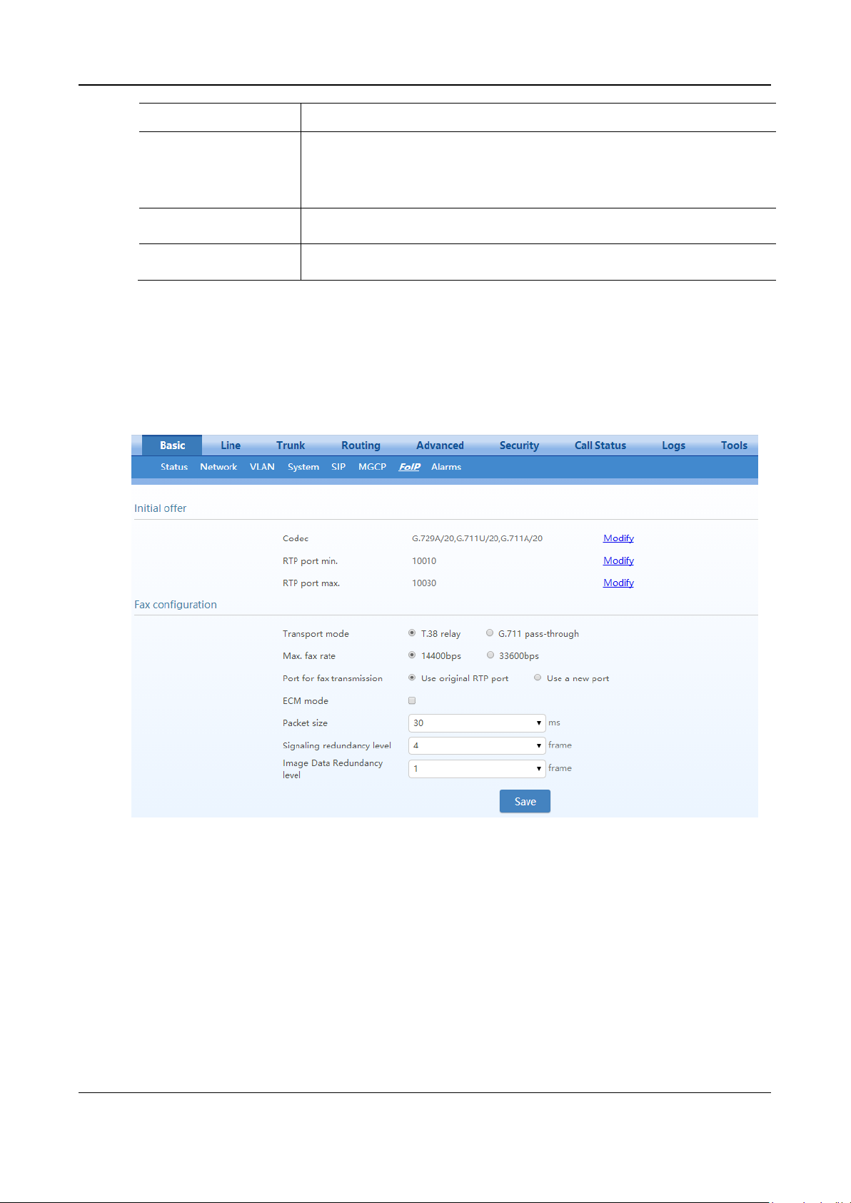
User Manual MX Series Voice Gateway
Name
Description
Using notify instead of
401/402
Set whether the gateways report “offhook events” to replace 401 messages in NTFY or
report “on-hook events” to replace 402 messages in NTFY when responding to messages
sent by the proxy server. Default not selected.
Selected: the gateways will use NTFY messages to replace 401 and 402 messages.
No name in default package
Select if a package name is included when the gateways reply to the default package.
Default not selected.
Keep connection when onhook
Select if the gateways actively cancel connection disconnect when subscribers hook on.
Default not selected.
2.2.9 FoIP
After login, click Basic>FoIP to open this interface.
Figure 2-28 Fax Configuration Interface (HX4E/MX8A)
48 New Rock Technologies, Inc.
Page 49
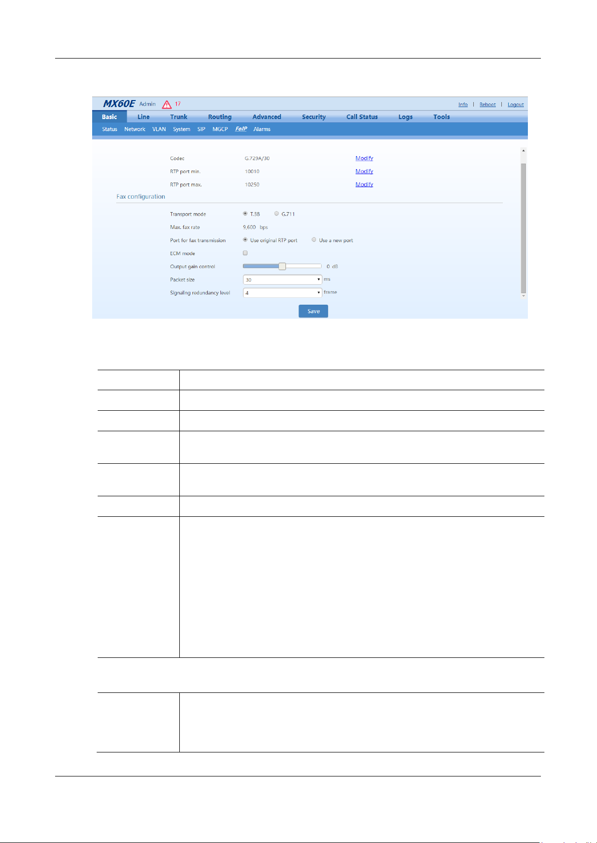
MX Series Voice Gateway User Manual
Name
Description
Initial offer
Codec
Click Edit, go to Basic>System page to configure. For details, see 2.2.4 System.
RTP port Min.
Click Edit, go to Advanced>Media stream page to configure. For details, see 2.6.5 Media
Stream.
RTP port Max.
Click Edit, go to Advanced>Media stream page to configure. For details, see 2.6.5 Media
Stream.
Fax configuration
Transport mode
The device supports two fax modes: T.38 and G.711 transparent transmission.
When fax messages are received or sent through an analog trunk, the G.711 transparent
transmission mode is required. When fax messages are received or sent through an IP trunk, a
T.38 or a G.711 transparent transmission mode needs to be selected according to an actual
requirement and the mode supported by the IP phone operation platform. If both T.38 and G.711
transparent transmission modes are supported, T.38 is recommended because it is more stable.
Enable G.711 pass-through according to the your device model:
HX4E/MX8A: Select G.711 pass-through in this area.
MX60/MX60E/MX120G: Select G.711 in this field, and then select Pass-through.
Adjustable parameters when G.711 pass-through is enabled (default values are recommended):
Receiving terminal
(Only supported by
MX60/
MX60E/MX120G
Re-INVITE: automatically select the codec according to the Re-INVITE negotiation result.
Pass-through: select G.711 pass-through.
To ensure normal operation of the pass-through function, make sure that G.711U/20 or
G.711A/20 is selected in Codec.
Figure 2-29 MX60/MX60E/MX120G Fax Configuration Interface
Table 2-11 Fax Configuration Parameters
New Rock Technologies, Inc. 49
Page 50

User Manual MX Series Voice Gateway
Name
Description
Allow opposite
terminal to switch
to T.38
When the device sends a fax message in G.711 transparent transmission mode, if the other party
sends a T.38 negotiation request, the device will respond to the request and automatically switch
to the T.38 mode.
Adjustable parameters when the T.38 is enabled (Default values are recommended.)
Max. fax rate
Select the maximum transmission rate of the fax service. 33600bps indicates the highest-rate fax
mode.
Port for fax
transmission
Set whether to use a new RTP port when the gateway switches to the T.38 mode. The default
value is Use original RTP port.
Use a new port: Indicates that a new RTP port is used.
Use original RTP port: Indicates that the original RTP port established during the call is used.
ECM mode
Enable the fax ECM mode.
HX4E/MX8: The default value is related to the transmission rate. When the maximum fax rate
is 14400 bps, the ECM mode is disabled by default. When the maximum fax rate is 33600 bps,
the ECM mode is enabled by default.
MX60/MX60E/MX120G: Disabled by default.
Output gain control
(Only supported by
MX60/MX60E/M
X120G)
Set the increment and decrement of the T.38 fax transmission gain. The value ranges from –6 to
+6 dB. The default value is 0 dB. –6 dB indicates an attenuation of 6 dB, and +6 dB indicates an
amplification of 6 dB.
Packet size
Set a data frame packet interval for T.38. The options include 30 ms and 40 ms. The default value
is 30 ms.
Signaling
redundancy level
Set the number of redundant data frames in T.38 data packets. The value range is 0–6 frames, and
the default value is 4 frames.
Image Data
redundancy level
(only
HX4E/MX8A)
Set the number of redundant images in T.38 data packets. The value range is 0–2, and the default
value is 1.
Type
Severity
Description
Red alarm
Critical
Indicates that a service-affecting or severe security condition has occurred that
requires corrective action as soon as possible.
Orange alarm
Major
Indicates the detection of a potential event that may results in a brute force login attack that
requires acknowledgment and further actions if necessary.
Waning
Minor
Indicates the detection of a potential event that may become more severe that requires
acknowledgement and further actions if necessary.
2.2.10 Alarm
With security event alarm, notification and tracking mechanism, the system administrator is allowed to
acquire security alarm status in time and take necessary actions to prevent malicious attacks.
The device provides the following alarm types based on the severity:
Table 2-12 Alarm Type
50 New Rock Technologies, Inc.
Page 51
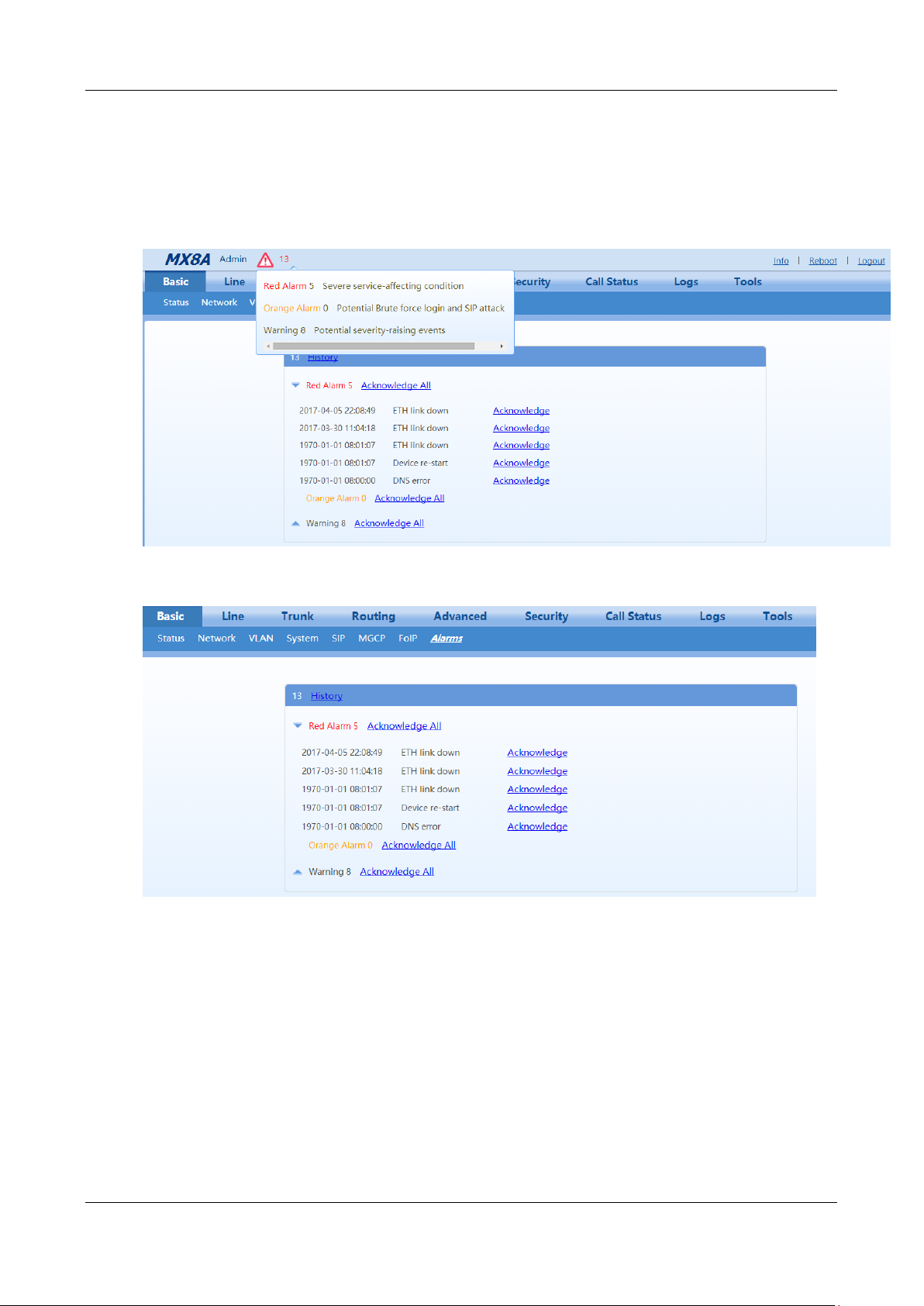
MX Series Voice Gateway User Manual
The alarm icon in the general information bar on the page displays the total number of security events.
Move the cursor to the icon, you may see the brief summary of the potential security issues.
Choose Basic > Alarm to view details of the security events and acknowledge the alarms.
Figure 2-30 Alarm Icon
Figure 2-31 Alarms Interface
You may do the following operations:
History: Click to download the security event log.
Acknowledge: Click to acknowledge the alarm.
Acknowledge All: Click to acknowledge all alarms of this type.
The acknowledged alarms will not be displayed but be kept in the security event log.
New Rock Technologies, Inc. 51
Page 52
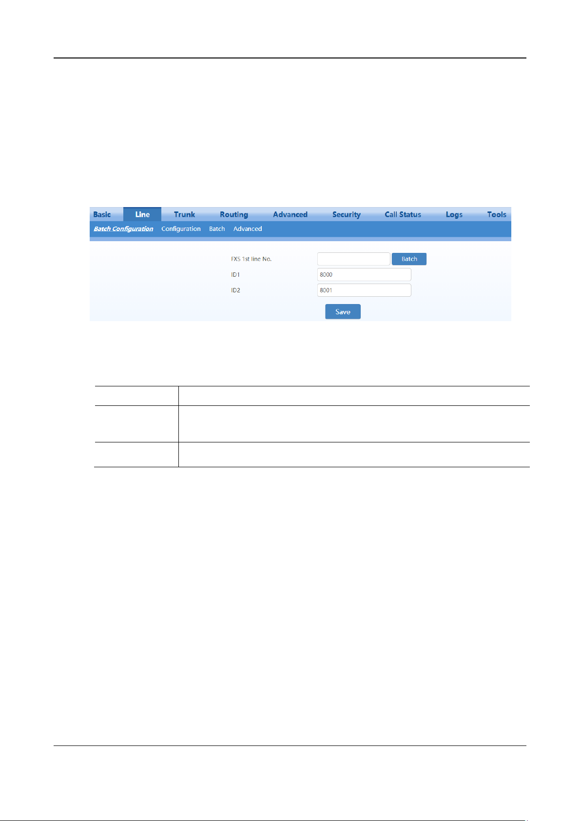
User Manual MX Series Voice Gateway
Name
Description
FXS 1st line No.
This number is used for the batch setup of subscriber line.
Click Batch after filling in initial number, the number of Line 1 adopts initial number; that of
Line 2 increases 1 progressively based on that of Line 1, and so on.
ID n
Fill in the telephone number associated with the subscriber line n (FXS port). This should be
manually performed if Batch mode is not used.
2.3 Line
2.3.1 Phone Number
The content below is only applicable to gateways with FXS ports.
After login, click Line > Batch Configuration (Phone number) to open the configuration interface.
Figure 2-32 Configuration Interface for Batch Configuration (Phone Number)
Table 2-13 Configuration Parameters of Batch Configuration (Phone Number)
2.3.2 Subscriber Line Features
The content below is only applicable to gateways with FXS ports.
After login, click Line > Configuration to open the configuration interface.
52 New Rock Technologies, Inc.
Page 53
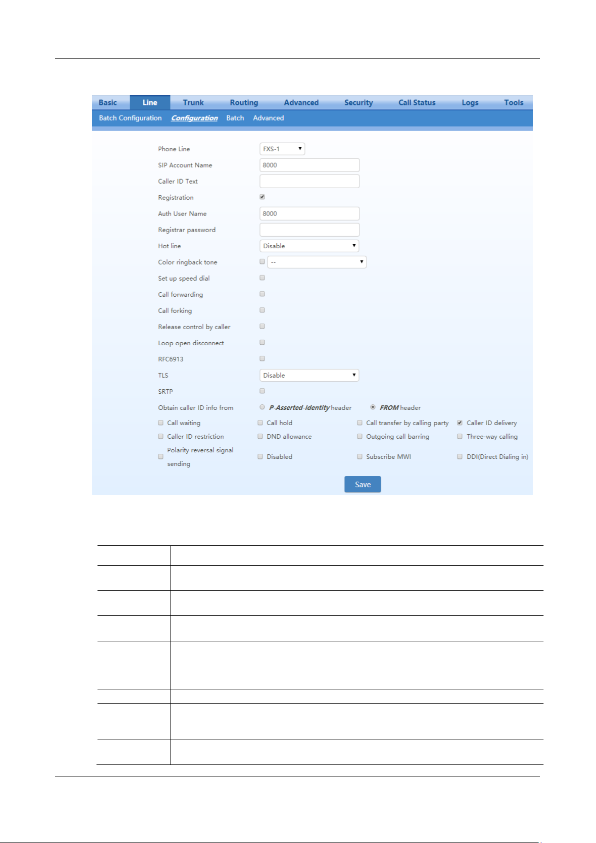
MX Series Voice Gateway User Manual
Name
Description
Phone line
Fill in the port number associated with this port. “FXS-n” corresponds to the Line>Batch
configuration>ID n.
SIP account
name
Fill in the number associated with this port.
Caller ID text
Fill in the display name which will be contained in the From field of SIP message. e.g. From: "Bob
" <sip:[email protected]>;tag=14340047091433920745-1, Bob is the display name.
Local SIP port
This parameter is displayed only when Multi port is selected in page Advanced>SIP. Set the port
used for receiving and sending SIP messages associated with the line.
If this parameter is not specified, the local port configured in Basic>SIP is used.
Note: This parameter is displayed only when Multi port is checked on Advanced>SIP page.
Registration
Select if this line is required to register to a soft switch. This is selected by default.
Auth user name
If Registration is selected, you should enter the user name for registering the line here.
This is not mandatory. If this parameter remains blank, the phone number of the extension set is
used.
Registrar
password
If Registration is selected, users must enter the authentication password for registering of this line
here.
Figure 2-33 Subscriber Line Configuration Interface
Table 2-14 Subscriber Line Configuration Parameters
New Rock Technologies, Inc. 53
Page 54

User Manual MX Series Voice Gateway
Name
Description
Note:
The following features are valid only in SIP protocol. When the gateways use MGCP protocol, features are controlled
by the proxy server without the need to be set on the gateway.
Hot line
Select if the gateway is required to automatically dial out the hotline number after offhook. By
default, hot line is disabled.
Disable: close this feature.
Immediate: automatically dial out the hotline number after offhook.
Delay mode: automatically dial out the hotline number when the offhook is timeout with a time
delay of 5 second by default. You can change the delay time by setting the parameter hotline
dialing delay on Line>advanced.
Color ringback
tone
Select to activate CRBT (Color Ring Back Tone), then choose an audio file as ring back tone.
There are two.dat files in the G.729 coding format (fring1.dat and fring2.dat) storage in MX for
factory default. You can upload .wav files through the Web GUI, for details, see 2.6.8 Greeting.
Set up speed dial
Select if the Speed dials is activated on this line. By default, this is not selected.
Speed dial
groups
Use "Abbreviated number-Phone number" (e.g. 20-13812345678).
Use a forward slash "/" to separate each group of abbreviated numbers.
The abbreviated numbers range from 20 to 49.
A maximum of 399 bytes can be configured.
Call forwarding
Select if Call forwarding is activated on this line. By default, it is not selected.
Unconditional
All incoming calls are forwarded to the telephone number specified in this parameter.
No Answer
All incoming calls are forwarded to the telephone number specified in this parameter when they are
not answered.
Busy
All incoming calls are forwarded to the telephone number specified in this parameter when the
extension is busy.
Call Forking
Select to activate call forking. Forking allows the device to simultaneously dial the extension along
with another telephone terminal (specified when function is activated). Either terminal may answer,
when one side picks up, ringing on the other side will end.
Release control
by caller
Select if the call release is controlled by the caller. By default, this is not selected.
Selected: the gateway will immediately release the call when caller hangs up; the gateway will not
release the call when called party hangs up as long as the caller is still off-hook until timeout (60
seconds by default);
Unselected: the gateway will immediately release the call upon either party hanging up the call.
Loop open
disconnect
Select only if the trunk of the PBX supports loop open signaling, in which the PBX takes the loop
open as the indication of disconnection. Note: Loop open interval can be configured on the
Advanced > Line page.
RFC6913
If this item is selected, the Fax over IP label carried in INVITE is supported.
TLS
If this option is enabled, the TLS server configured on Basic > SIP page is used for both
registration and calls over this line.
If this option is not enabled, the default registration server and proxy server are used.
SRTP
Enable SRTP.
Obtain caller ID
info from
If a received INVITE message carries From and P-Asserted-Id header fields, the caller
identification number will be selected according to this parameter.
If the received INVITE message does not carry the P-Asserted-Id header field, caller identification
numbers are obtained from the From header field.
P-Asserted-Id field preferentially: The caller identification information is preferentially obtained
from the P-Asserted-Id field in the INVITE message.
From field only: The caller identification information is obtained from the From field in the
INVITE message.
From field only is selected by default.
54 New Rock Technologies, Inc.
Page 55

MX Series Voice Gateway User Manual
Name
Description
Registration
subscription
The device subscribes the registration status of the line. If the subscription is successful, the SIP
server sends a NOTIFY message for notification of the registration status of the line.
Note: This parameter is displayed only when IMS is selected and Registration subscription is
checked on Advanced>SIP page.
Call waiting
Select if Call waiting is activated on this line. By default this is not selected.
Call hold
Select it to enable Call Hold on this line. By default this is not selected.
Note: If this function is enabled, the gateways will automatically activate Call Transfer.
Call transfer by
calling party
Select if Caller Transfer is activated on this line. By default, this is not selected. When A calls B, B
picks up the call and A transfers the call to C.
Note: The call hold must be activated before caller transfer.
Caller ID
delivery
Set whether the calling number is sent to the called party. This feature requires the support of
softswtich. By default this is selected.
Caller ID
restriction
Set whether the number of this telephone is sent to the called party with support from platform. By
default this is not selected
DND allowance
Select if Do Not Disturb is allowed to enable on this line. By default, this is not selected.
Outgoing call
barring
Select if outgoing calls are barred on this line. By default, this is not selected.
Three-way
calling
Select if 3-way service is activated, and by default this is not selected.
Polarity reversal
signal sending
Select if reverse polarity signal sending is activated on this line. By default, this is not selected.
Note:
The gateways will provide reverse polarity signal when the phone is connected after this feature is
activated.
Disabled
Select to disable the line, in which the FXS port no longer supplies current to the phone. By default,
this is not selected.
Subscribe MWI
Select if voice mail service is activated. This is not selected by default. (Also see MWI Re-
subscription on page Advanced > SIP.)
DDI (Direct
Dialing in)
Set whether DDI (Direct Dialing In) is activated, By default, this is not selected. Different from
FXS, DDI is only used for incoming calls, and the gateways will not send dial tone after off-hook
(calling in) on user side.
Note: Reverse polarity signal must be activated on the gateways when DDI is used.
Recording
Select if recording service is activated, and by default this is not selected.
2.3.3 Subscriber Line Batch (Unavailable on the HX4E)
The content below is only applicable to gateways with FXS ports.
After login, click Line> Batch to open the configuration interface.
Step 1
Step 2
New Rock Technologies, Inc. 55
Click , the following interface is shown. Choose batch configured features and click OK.
Click to activate this function to configure this parameter. For details of the parameter, see
Line > Configuration
.
Page 56
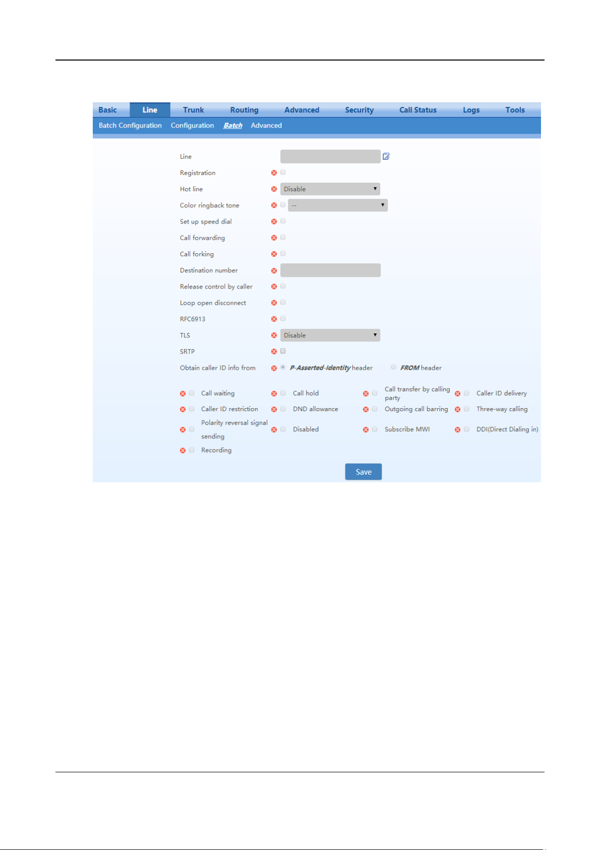
User Manual MX Series Voice Gateway
Figure 2-34 Feature Batch Configuration Interface
2.3.4 Subscriber Line Characteristics
The content below is only applicable to gateways with FXS ports.
After login, click Line > feature to open the configuration interface.
56 New Rock Technologies, Inc.
Page 57
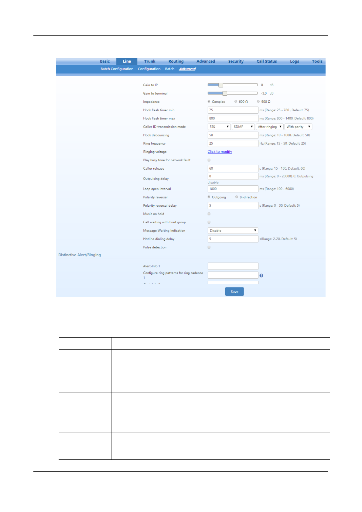
MX Series Voice Gateway User Manual
Name
Description
Gain to IP
Adjust the voice volume from the analog extension. The default is 0. Taking decibel as the unit,
setting range is -3 ~ +3 decibels. -3 means declining of 3 decibels; +3 means the amplification of
3 decibels.
Gain to terminal
Adjust the voice volume to the analog extension. The default is -3. Taking decibel as the unit,
setting range is -6 ~ +3 decibels. -3 means declining of 3 decibels; +3 denotes the amplification
of 3 decibels.
Impedance
Select the parameter of FXS port line impedance. The optional values as below:
Complex (default value)
600 (ohm)
900 (ohm)
Hook flash time min
Used by the gateway to detect Hook Flash event, the default is 75 milliseconds.
The gateway will ignore any flash that fall short of the shortest flash time. Generally, this value
should not be less than 75 milliseconds.
Figure 2-35 Subscriber Line Characteristics Configuration Interface
Table 2-15 Subscriber Line Characteristics Configuration Parameter
New Rock Technologies, Inc. 57
Page 58

User Manual MX Series Voice Gateway
Name
Description
Hook flash time
max
Used by gateway to detect hook flash, the default is 800 milliseconds.
The gateway will regard the flash duration between Hook flash time min and Hook flash time
max as effective flash. Any flash lasting over the longest time will be considered by gateway as
hang up. Generally, this value should not be less than 800 milliseconds.
Caller ID
transmission mode
Select transmission mode of Caller ID signal from the FXS port to the phone.
FSK or DTMF
SDMF or MDMF
Sending Caller ID data before or after ringing
Sending Caller ID data with or without parity
Hook debouncing
Used by gateway to avoid phone status errors, with default of 50 milliseconds.
When the duration from hang-up to off-hook falls short of this value, the gateway will ignore the
status variation, and consider that the phone remains in hang-up status. In opposite case, the
gateway will ignore the status variation, and consider the phone remains in off-hook status.
Effective range of setting is 10~1000 milliseconds.
Ring frequency
Set the ringing frequency to be transmitted by gateway to the phone, ranging from 15 to 50 Hz,
with default of 20 Hz.
Play busy tone for
network fault
Play a busy tone upon off-hook when a network fault occurs.
Caller release
Set the delay release time of line as caller control method, with a default of 60 seconds. Effective
range of setting is 15~180 seconds.
This parameter is used in combination with the Release control by caller parameter in
Line>Feature.
Outpulsing delay
Used when gateway’s FXS port is connected with the trunk interface of PBXs. For calls from
gateway to PBX, gateways will relay the extensions to PBX after the delay set here. Setting of 0
means no extension number relay. The default is 0 milliseconds.
Loop open interval
This parameter is used with the loop open disconnection request. The range is from 100 ms to
6000 ms.
Polarity reversal
Set the trigger for polarity reversal, the default is Outgoing.
Outgoing: transmit reverse polarity signal only when the outbound is connected;
Bi-direction: transmit reverse polarity signal for the connection of both inbound and out
bound calls.
Polarity reversal
delay
The delay time from a call being answered to the transmission of reverse polarity signal. The
default value is 3 in seconds. Effective range of setting is 0 - 30 seconds.
Music on hold
Choose whether to play the background music while call waiting. This is not selected by default.
Call waiting with
hunt group
Choose whether to activate hunt group feature for call waiting. Default not selected.
Message waiting
indication (MWI)
Select the lighting method of message waiting indicator of voice mail here: None, Polarity
reversed, FSK, high voltage lighting.
Message waiting indicator refers to the special LED on a phone that lights up upon receiving a
voice message. It is essential to understand whether the phone supports the indicator and lighting
method when selecting the lighting method.
Hotline dialing relay
This parameter specifies the delay time before the preset hotline number is automatically dialed
after hook-off. The default value is 5 seconds, and the value range is 2 to 20 seconds. This
parameter works only if the delay mode is set for hotline function on Line>Feature page. See
Table 2-14.
Pulse detection
Enable it to support connecting with a rotary dial phone.
Distinctive
Alert/Ringing
Set the parameter Alert-Infon according to the “Alert-Info” value provided on the SIP server.
When the “Alert-info” value of received INVITE message matches with the Alert-Infon, ring
cadence n is activated.
Alert-Info 1
Match with ring cadence 1.
58 New Rock Technologies, Inc.
Page 59
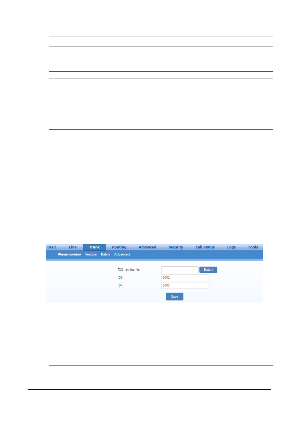
MX Series Voice Gateway User Manual
Name
Description
Configure ring
patterns for ring
cadence 1
Configure ring patterns for ring cadence 1.
e.g. 1: if the ring patterns are set to 2, 500, 500, 1000, 3000, the ringing cadence is 0.5s on, 0.5s
off; 1s on, 3s off.
e.g. 2: if the ring patterns are set to 2000, 4000, the ringing cadence will be 2s on, 4s off.
Alert-Info 2
Match with ring cadence 2.
Configure ring
patterns for ring
cadence 2.
Configure ring patterns for ring cadence 2. It is used with Alert-Info 2.
Alert-Info 3
Match with ring cadence 3.
Configure ring
patterns for ring
cadence 3
Configure ring patterns for ring cadence 3
Alert-Info 4
Match with ring cadence 4.
Configure ring
patterns for ring
cadence 4
Configure ring patterns for ring cadence 4. It is used with Alert-Info 4.
Name
Description
FXO 1st line No.
This number is used for the batch setup of trunk line.
Click Batch after filling in initial number, the number of Line 1 adopts initial number; that of
Line 2 increases 1 progressively based on that of Line 1, and so on.
ID n
Fill in the telephone number associated with the trunk n (FXO port). This should be manually
performed if Batch mode is not used.
2.4 Trunk
2.4.1 Phone Number
Only a gateway with FXO ports can display this interface.
After login, click Trunk > Phone number to open the configuration interface.
Figure 2-36 Phone Number Configuration Interface
Table 2-16 Configuration Parameters of FXO Phone Number
New Rock Technologies, Inc. 59
Page 60
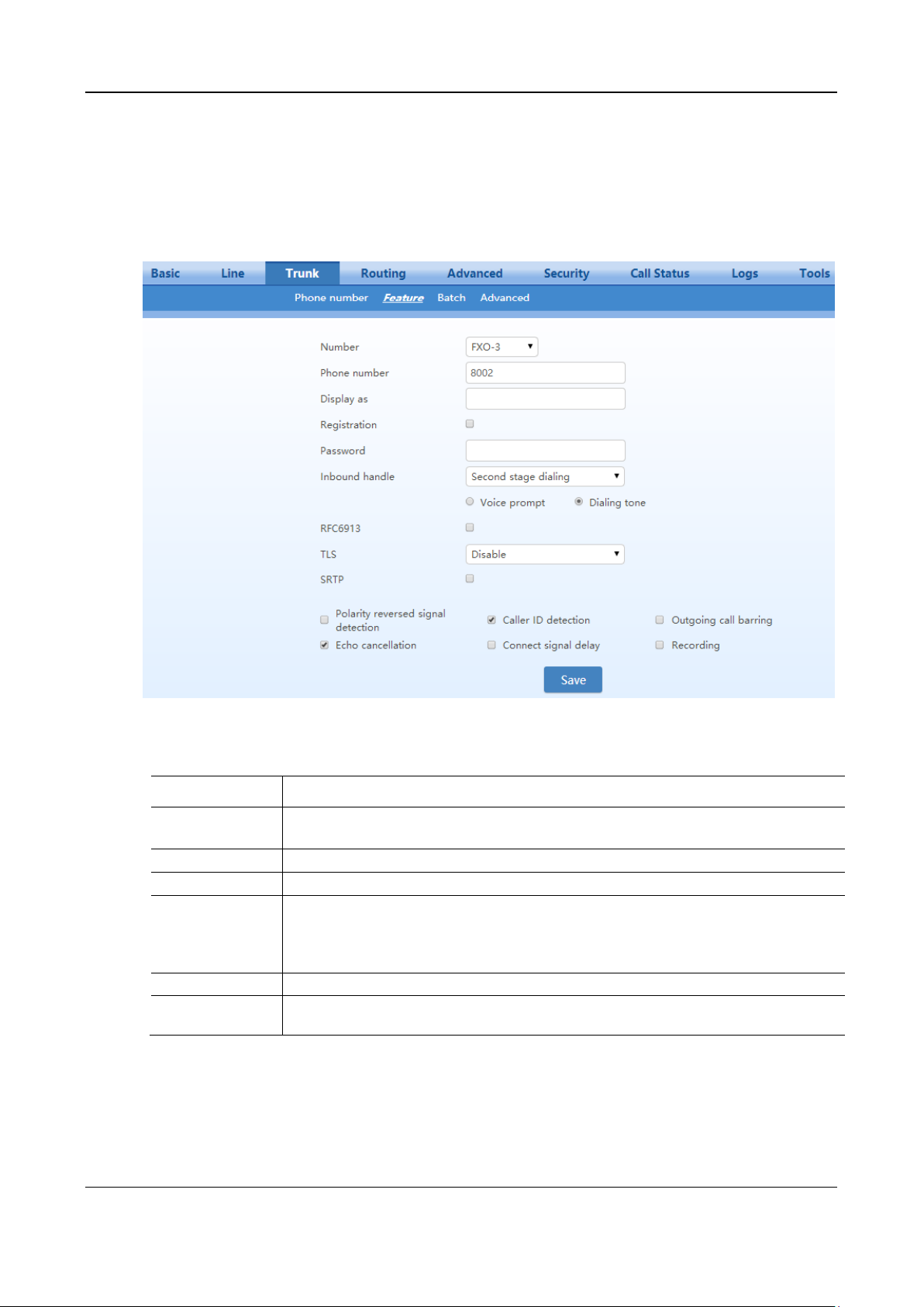
User Manual MX Series Voice Gateway
Name
Description
Number
Select a trunk line required to configure. “FXO-n” corresponds to the Trunk>Phone
number >ID n.
Phone number
Display phone number associated with the trunk set in Trunk>Phone number
Display as
Fill in the display name associated with this port.
Local SIP port
Set the port used for receiving and sending SIP messages on the line.
If this parameter is not specified, the local port configured in Basic>SIP is used.
This parameter is displayed only when multi port is selected in page Advanced>SIP.
Note: This parameter is displayed only when Multi port is checked on Advanced>SIP page.
Registration
Select if this trunk registers with the SIP registration server. By default, this is not selected.
Password
If Registration is selected, the authentication password for registering this line must be entered
here.
2.4.2 Trunk Features
Only a gateway with FXO ports can display this interface.
After login, click Trunk > Feature to open the configuration interface.
Figure 2-37 Trunk Line Features Configuration Interface
Table 2-17 Configuration Parameters of Trunk Features
60 New Rock Technologies, Inc.
Page 61

MX Series Voice Gateway User Manual
Name
Description
Note:
The following features are valid only in SIP protocol. When the gateways use MGCP protocol, the control of all call
services is provided by the proxy server without the need of these setting.
Inbound handle
The gateways provide three scenarios for handling incoming calls on the FXO trunk:
Binding: when a telephone call reaches the FXO port, the gateways will route the call to a
FXS port according to the DID number bound with the port.
Note: Setting a number to be bound is required or this setting is invalid.
Second-stage dialing: when a telephone call reaches the trunk port, the gateways will provide
the second dial tone and route the call according to the extension number entered. Dialing tone
or voice prompt file can be changed by user.
Direct: the gateways will route the incoming call on FXO port n to the corresponding FXS
port n. For example, a call made to the first FXO port is forwarded to the first FXS port.
Note: Direct applies only to a device having both FXO and FXS ports.
Voice prompt
Play the second dial prompt uploaded on Advanced>Greeting file page
Dialing tone
Play the second dial tone configured on Advanced>Tones page.
RFC6913
If this item is selected, the Fax over IP label carried in INVITE is supported.
TLS
If this option is enabled, the TLS server configured on Basic > SIP page is used for both
registration and calls over this line.
If this option is not enabled, the default registration server and proxy server are used.
SRTP
Enable SRTP.
Registration
subscription
Periodically send subscription messages to the SIP server. The period of sending the subscription
messages is the same as the Registration expiration in Basic >SIP.
Note: This parameter is displayed only when IMS is selected and Registration subscription is
checked on Advanced>SIP page.
Polarity reversal
signal detection
If a PSTN line supports reverse polarity, make the selection here. Or this setting is invalid. By
default, this is not selected.
Caller ID detection
Select to enable the detection function of caller ID for this FXO port. By default, this is not
selected.
Outgoing call
barring
Select if this FXO port bars outgoing call service to the PSTN. By default, this is not selected.
Echo cancellation
Select if echo cancellation is enabled for this FXO (Line).By default, this is selected.
Connect signal
delay
After making an outgoing call from a FXO port, the gateway will send a 200 OK message to the
platform with a delay if this parameter is selected. If unselected, the system sends a 200 OK
message to the platform after off hook on the FXO port. Also see Answer delay on page
Trunk>Advanced.
Recording
Select if recording service is activated. This is not selected by default.
2.4.3 Trunk Batch (Unavailable on the HX4E)
Only a gateway with FXO ports can display this interface.
After login, click Trunk >Batch to open the configuration interface.
Step 1
New Rock Technologies, Inc. 61
Step 2
Click , the following interface is shown. Choose batch configured trunks and click OK.
Click to activate this function to configure this parameter. For details of the parameter, see
Trunk > Feature
.
Page 62
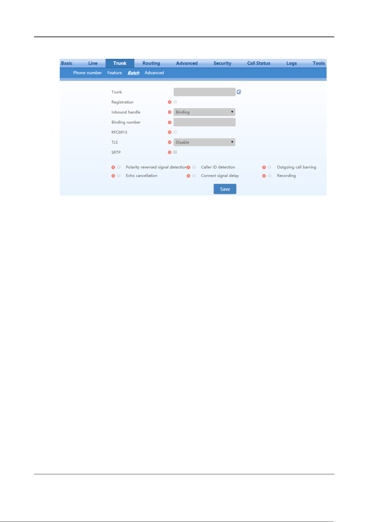
User Manual MX Series Voice Gateway
Figure 2-38 Trunk Batch Configuration Interface
2.4.4 Trunk Characteristics
Only a gateway with FXO ports can display this interface.
After login, click Trunk > Advanced to open the configuration interface.
62 New Rock Technologies, Inc.
Page 63
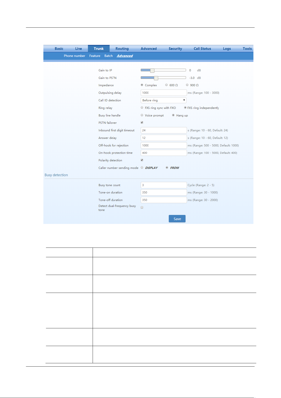
MX Series Voice Gateway User Manual
Name
Description
Gain to IP
Adjust the volume of the voice sent from the PSTN to the device.
Increase the value when the volume received by internal party is low.
Range: -3.0 - +9.0 dB. It is set to 0 dB by default.
Gain to PSTN
Adjust the voice volume sent from the device to the PSTN.
Increase the value when the volume received by external party is low.
Range: -6.0 - +3.0 dB.
Impedance
Set the parameter of FXO impedance, with the default of 600 ohm. The optional settings are
below:
Complex (default value)
600 (ohm)
900 (ohm)
Outpulsing delay
Set the time interval between the FXO going off-hook and the outpulsing of the first digit to
the PSTN. The default is 600 in milliseconds.
Note: This parameter is used to match the digit receiving response time of the PSTN PBX.
Call ID detection
Before ringing;
After ringing. The After ringing mode is generally used.
Figure 2-39 Trunk Characteristics Configuration Interface
Table 2-18 Trunk Characteristics Configuration Parameter
New Rock Technologies, Inc. 63
Page 64

User Manual MX Series Voice Gateway
Name
Description
Ring relay
Select whether to relay the ring of inbound call to the FXS port when the Inbound handle
mode for the FXO port is selected as Direct. The default is Phone ring independently.
Busy line handle
Either a voice prompt or hanging up can be applied to FXO port when an incoming call goes
to the FXS port which is in busy. This only applicable when the Inbound handle mode for
the FXO port is selected as Direct.
PSTN failover
Select to route a call to the PSTN through an FXO port when the IP network fails or if there
is no response to the call request. Default selected.
Inbound first digit
timeout
Set the timeout of calling DTMF on FXO port for inbound calls, ranging from 10-60
seconds, with default of 24 seconds.
Answer delay
Set the delay time for sending 200 OK, ranging from 10 to 60 seconds, with default of 12
seconds.
This parameter is used in combination with the Connect signal delay in Trunk >Trunk
page. See Table 2-17.
Off-hook for rejection
This parameter is used to specify how to reject an incoming call in the Direct mode (see
Table 2-17) for the FXO port.
For inbound calls to an FXO port, if the associated FXS port is busy, the gateway will hang
up after off hook according to the time set by the parameter, so as to refuse the upcoming
call. The duration of the off hook is 500~5000 milliseconds, with a default of 600
milliseconds
On-hook protection
time
Protection period following hang up of FXO port. During this period, the gateway ignores
any voltage variation of the line. Value range is 100~5000 milliseconds, the default is 400 in
milliseconds.
Polarity detection.
Choose whether to activate the detection of reverse polarity signal of FXO port. Note the
detection will work only when the trunk supports polarity reversal.
Caller number sending
mode
DISPLAY: include the incoming call number detected at the FXO port in the Display
field and send it to the peer end. The From field carries the phone number associated with
the FXO port.
FROM: include the incoming call number detected by FXO in the From field and send it
to the peer end. No Display information is carried.
Busy detection
Busy tone count
Set the number of consecutive times the gateway detects busy tone signals.
Gateways will regard the busy tone signal with the repeat times specified here as a hang-up
signal. Default is 2, effective range is 2 ~ 5(cycle).
Tone-on duration
Set duration of busy tone signal, the default is 350 in milliseconds.
Tone-off duration
Set the interval time of busy tone, the default is 350 in milliseconds.
Detect dual-frequency
busy tones
To detect dual-frequency busy tones.
Busy tone frequency
If Detect dual-frequency busy tones is enabled, you need to specify the frequency to be
detected.
Unit: Hz.
2.5 Routing
2.5.1 Digit Map
After login, click Routing>Digit Map to open the dialing rules interface.
64 New Rock Technologies, Inc.
Page 65
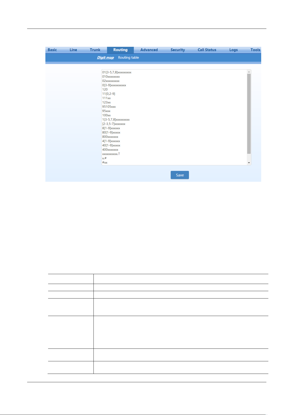
MX Series Voice Gateway User Manual
Digit map
Description
x
Represents one digit between 0-9.
.
Represents more than one digit between 0-9.
##
After ## is detected, the gateway terminates the process of receiving digits.
## also functions as a special dial string for users to receive gateway IP address and version
number of firmware by default.
xxxxxxxxxx.T
For a number with 10 digits, or less than 10 digits, the device terminates receiving digits and
sends detected numbers if the duration of no dialing period exceeded the value of the
Interdigit timer parameter. For a number with more than 10 digits, the device terminates
receiving digits and sends detected numbers if the duration of no dialing period exceeded the
value of the Complete entry timer parameter. Interdigit timer and Complete entry timer
can be set on Basic>System page.
x.#
If subscribers press # key after dial-up, the gateways will immediately terminate the process of
receiving digits and send all the numbers before # key.
*xx
Terminate after receiving * and any two-digit number. *xx is primarily used to activate feature
codes for supplementary services, such as CRBT, Call Transfer, Do not Disturb, etc.
Figure 2-40 Configuration Interface for Digit Map
Dialing rules are used to effectively detect completed received number sequences that are ready to be sent
in order to reduce connection time of telephone calls.
The maximum number of rules that can be stored in gateways is 250. Each rule can hold up to 32
numbers and 38 characters. The total size of the dialing rules table (all dialing rules) can be up to 2280
bytes.
The default digit map only contains system function rules. To customize the digit map, please choose the
country in Advanced >Tones and input the rules you want in the text box. The following provides
descriptions of typical rules:
Table 2-19 Description of Digit Map
New Rock Technologies, Inc. 65
Page 66

User Manual MX Series Voice Gateway
Digit map
Description
#xx
Terminate after receiving # and any two-digit number. #xx is primarily used to stop feature
codes for supplementary services, such as CRBT, Call Transfer, Do not Disturb, etc.
[2-3,5-7]xxxxxxx
The gateway terminates receiving digits after receiving eight digits starting with any digits
except 1, 4, or 9.
02xxxxxxxxx
The gateway terminates receiving digits after receiving 11 digits starting with 02.
013xxxxxxxxx
The gateway terminates receiving digits after receiving 12 digits starting with 013.
13xxxxxxxxx
The gateway terminates receiving digits after receiving 11 digits starting with 13.
11x
The gateway terminates receiving digits after receiving three digits starting with 11.
9xxxx
The gateway terminates receiving digits after receiving five digits starting with 9.
17911 (e.g.)
Send away when the set number, e.g. 17911, is received.
Dial rules by default are as follows:
01[3-5,7,8]xxxxxxxxx
010xxxxxxxx
02xxxxxxxxx
0[3-9]xxxxxxxxxx
120
11[0,2-9]
111xx
123xx
95105xxx
95xxx
100xx
1[3-5,7,8]xxxxxxxxx
[2-3,5-7]xxxxxxx
8[1-9]xxxxxx
80[1-9]xxxxx
800xxxxxxx
4[1-9]xxxxxx
40[1-9]xxxxx
400xxxxxxx
xxxxxxxxxx.T
x.#
#xx
*xx
##
2.5.2 Routing Table
After login, click Routing > Routing Table to open the configuration interface.
66 New Rock Technologies, Inc.
Page 67
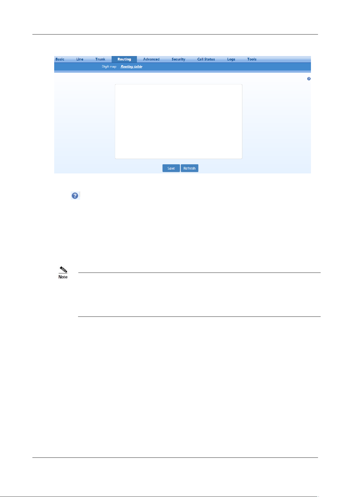
MX Series Voice Gateway User Manual
Rules must be filled out without any blank at the beginning of each line; otherwise the
data will not be validated even if the system prompts successful submittal.
The routing table is empty by default. The gateways will direct a call to the SIP proxy
server when there is no matched rule for the call.
Figure 2-41 Routing Table Configuration Interface
Click to open the illustrative interface for routing configuration.
The routing table with a capacity of 500 rules provides two functions including number transformation
and call routing assignment.
The device will match a rule from top to bottom.
The format of number transformation is
Source Number Transformation Method
Take FXS 021 REMOVE 3 as an example. It indicates that, for a call from the FXS port (on a subscriber
line), the first three digits area code 021 is removed from the called number.
Where FXS is the source, 021 is the number, and REMOVE 3 indicates the method of number
transformation.
The format of routing rules is
Source Number ROUTE Routing Destination
Take IP 800[0-1] ROUTE FXO 1-2 as an example. It means that calls from IP with called number prefix
8000 or 8001 are routed to FXO port in a sequential order. Namely, FXO Port 2 is selected when FXO
Port 1 is busy and so on.
Where IP is the source, 800[0-1] is the number, and FXO 1-2 is the routing destination.
New Rock Technologies, Inc. 67
Page 68

User Manual MX Series Voice Gateway
Name
Description
Source
There are three types of source: IP, FXS (Phone/fax) and FXO (Line).
The IP indicates any IP addresses. IP [xxx.xxx.xxx.xxx] indicates a specific address. IP
[xxx.xxx.xxx.xxx:port] indicates a specific IP address and a specific port number.
The FXS or FXO indicates any FXS or FXO port. FXS1, FXO2, FXS [1-2], or similar indicates a
specific port.
Number
Specify a called party number.
You can specify a calling party number in the form of CPN + number.
The number may be denoted with digits 0-9, "*", ".", "#", " x ", etc., and follows the format of the
dialing rules.
Here are a few ways you can format the number:
Designate a specific number: eg.114, or 61202700
Designate a number matching a prefix: such as 61xxxxxx.
Specify a number scope. For example, 268[0-1, 3-9] specifies any 4-digit number starting with 268
and followed by a digit between 0-1or 3-9
Processing
Mode
Description and Example
KEEP
Keep number. A positive digit following KEEP indicates the number of digits at the beginning of
the sequence that is kept; a negative digit indicates numbers of digits at the end of the sequence
that is kept.
Example: FXS 02161202700 KEEP -8
Keep the last 8 digits of the called number 02161202700 for calls from FXS. The transformed
called number is 61202700.
REMOVE
Remove number. A positive digit following REMOVE means to remove the number of digits at
the beginning of the sequence; a negative number means to remove the number of digits at the
end of the sequence.
For example: FXS 021 REMOVE 3
Remove 021 of the called number beginning with 021 for calls from FXS.
ADD
Add prefix or suffix to number. If the number following ADD is positive, it is a prefix; if it is
negative, it is a suffix.
Example 1:
FXS1 CPNX ADD 021
FXS2 CPNX ADD 010
Add 021 in front of calling numbers for calls from FXS port 1; add 010 in front of calling
numbers for calls from FXS port 2.
Example 2: FXS CPN6120 ADD -8888
Add 8888 at the end of the calling number starting with 6120 for calls from an FXS (Phone/fax)
port.
REPLACE
Number replacement. The replacing number follows REPLACE.
Example: FXS CPN88 REPLACE 2682000
Replace the calling number beginning with 88 for calls from FXS port with 2682000.
For details of Source and Number, see Table 2-20.
For details of Number Transformation and Routing Destination, see Table 2-21 and Table 2-22
respectively.
Table 2-20 Routing Table Format
Table 2-21 Number Transformations
68 New Rock Technologies, Inc.
Page 69

MX Series Voice Gateway User Manual
Processing
Mode
Description and Example
REPLACE
(continued)
Another use of REPLACE is to replace the specific number based on another number associated
with the call. For example, replacing the calling number according to the called number.
Examples:
FXS 12345 REPLACE CPN-1/8621
FXS CPN13 REPLACE CDPN0/0
For calls from FXS ports with called party number of 12345, remove one digit at the end of the
calling number and add 8621; for calls from FXS ports with calling party number starting with
13, add 0 at the beginning of the called number.
END or ROUTE
End-of-number transformation. From top to bottom, number transformation will be stopped when
END or ROUTE is encountered; the gateways will route the call to the default routing upon
detecting END, or route the call to the designed routing after detecting ROUTE.
Example 1:
FXS 12345 ADD -8001
FXS 12345 REMOVE 4
FXS 12345 END
Add suffix 8001 to the called number starting with 12345 for calls from FXS ports, then remove
four digits in front of the number to end number transformation yielding 58001.
Example 2:
IP [222.34.55.1] CPNX. REPLACE 2680000
IP [222.34.55.1] CPNX. ROUTE FXS 2
For calls from IP address 222.34.55.1, calling party number is replaced by 2680000, and then the
call is routed to FXS port 2 with the new calling party number.
CODEC
Designate the use of a codec, such as PCMU/20/16, where PCMU denotes G.711, /20 denotes
RTP packet interval of 20 milliseconds, and /16 denotes echo cancellation with 16 milliseconds
window. PCMU/20/0 should be used if echo cancellation is not required to activate.
Example: IP 6120 CODEC PCMU/20/16
PCMU/20/16 codec will be applied to calls from IP with called party number starting with 6120.
RELAY
Insert prefix of called party number when calling out. The inserted prefix number follows
RELAY.
Example:
IP 010 RELAY 17909
For calls from IP with called party numbers starting with 010, digit stream 17909 will be
outpulsed before the original called party number is sent out.
Example:
IP 010 RELAY 17909 ,,,
For a call from the IP end with the called number starting with 010, before the call is made, 17909
is automatically dialed first and three seconds later, the called number is dialed.
One comma "," represents one second.
Destination
Description and Example
ROUTE NONE
Calling barring (also known as “blacklist”).
Example: IP CPN[1,3-5] ROUTE NONE
Bar all calls from IP, of which the calling numbers start with 1, 3, 4, and 5.
Block all calls from IP numbers starting with 1, 3, 4, 5
Table 2-22 Routing Destination
New Rock Technologies, Inc. 69
Page 70

User Manual MX Series Voice Gateway
Destination
Description and Example
ROUTE FXS
Route a call to FXS port(s).
Example 1: IP 800[0-3] ROUTE FXS 1-2
Select a port in sequential order.
Example 2: IP 800[0-3] ROUTE FXS 1
Direct this call to FXS port 1.
Example 3:
IP 800[0-3] ROUTE FXS 1-2/R
Select a port in round-robin order
Example 4: IP 800[0-3] ROUTE FXS 1-2/G
Select all idle ports and provide ringing.
ROUTE FXO
Route a call to FXO port(s).
Example 1: IP x ROUTE FXO 1-2
Select a port in sequential order.
Example 2: IP 800[0-1] ROUTE FXO 1-2/R
Select a port in round-robin order.
ROUTE IP
Route a call to the SIP proxy server
Example: FXS 021 ROUTE IP 228.167.22.34:5060
228.167.22.34:5060 is the IP address and port of the platform.
2.5.3 Examples of Routing Rules
Examples of how routing table can be used to implement features:
1) Assigning One Phone with Dual Numbers
2) Hunt Group
3) Outbound Call Barring
4) Trunk Group for Outbound Calling
Assigning One Phone with Dual Numbers
For example, an analog extension of an FXS port, FXS1, of HX4E can be associated with two phone
numbers: a PSTN number 61202701 and an extension number 1001. The PSTN number is used for direct
inward dialing and the extension number is used for intercom. This feature can be supported by
configuring the FXS1 number as 61202701 and adding the following routing rule to the routing table:
FXS 1001 ROUTE FXS 1
Hunt Group
A hunt group is a group of extensions, to which an inbound call is terminated following certain rules.
Here is an example of terminating incoming calls from analog trunks to a hunt group consisting of ports
FXS1 and FXS2 in round-robin fashion:
FXO x ROUTE FXS 1-2/R
70 New Rock Technologies, Inc.
Outbound Call Barring
Restrict users to make certain calls, such as an international call. Examples are as follows:
Page 71

MX Series Voice Gateway User Manual
Routing Setting
Description
FXS[1] 0 ROUTE NONE
A calling starting with 0 is barred from dialing using the phone set at FXS1 port
FXS[1-2] 00 ROUTE NONE
A calling starting with 00 is barred from dialing using the phone set at FXS1 to
FXS2 port.
International call is not allowed.
FXS CPN2 ROUTE NONE
The telephone whose calling number starts with 2 at an FXS port is not allowed
to make calls.
Trunk Group for Outbound Calls
An outbound trunk group consists of a set of trunks which are used for outbound calling following certain
rules. Here is an example of routing all outbound calls from FXS port to the trunk group consisting of
ports FXO1 to FXO4 in sequential fashion:
FXS x ROUTE FXO 1-4
Further, we set up the trunk group such that it is used only by calls to destinations with prefix 6120:
FXS 6120 ROUTE FXO 1-4
2.6 Advanced Configuration
2.6.1 System
After login, click Advanced > System to open this interface.
New Rock Technologies, Inc. 71
Page 72
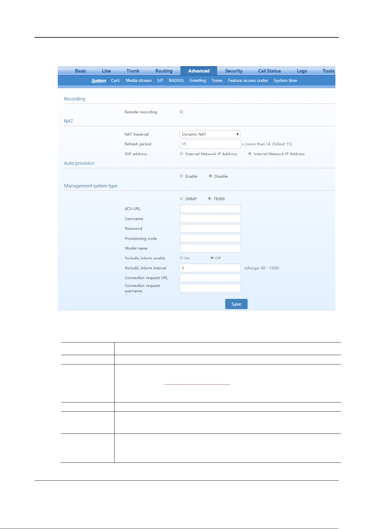
User Manual MX Series Voice Gateway
Name
Description
Recording
Remote recording
Call recordings are stored on an external Windows or Linux based recording server, on which
the agent provided by New Rock collects and stores the call recording files. For more
information, see the Recording Agent User Guide.
Set this parameter to the IP address of the server.
Note: The recording function needs to be enabled for the subscriber line.
NAT
NAT traversal
Gateways support several mechanisms for NAT traversal. Usually, static NAT is used when a
fixed public IP address is available. It is necessary to perform port mapping or DMZ function on
router when choosing dynamic or static NAT.
Refresh period
The refresh time must be filled in here when choosing dynamic NAT. Refresh time interval shall
be determined by giving consideration to the NAT refresh time of the LAN router where the
gateway is located. Gateway’s NAT holding function will carry out periodic operation according
to this parameter. With seconds as its unit, default value of 60 seconds.
Figure 2-42 Interface of system advanced configuration
Table 2-23 NAT Configuration Parameters
72 New Rock Technologies, Inc.
Page 73
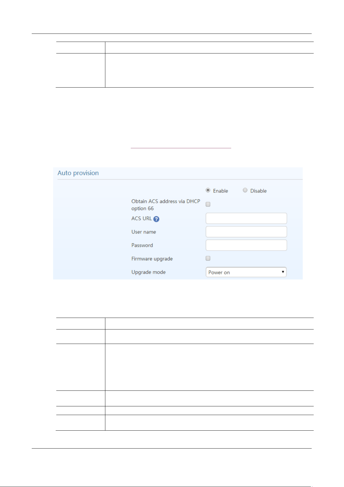
MX Series Voice Gateway User Manual
Name
Description
SDP Address
External network IP address: Use NAT public address.
Internal network IP address: Use the gateway’s IP address.
Note: External network IP address is effective when the device successfully obtains NAT
public address.
Name
Description
Obtain ACS address
via DHCP option 66
FTP/TFTP/HTTP/HTTPS ACS (Auto Provisioning Server) address is obtained by using option
66 of the DHCP.
ACS URL
Manually configure the address of ACS which could be a TFTP, FTP, HTTP or HTTPS server.
tftp://ACS address
ftp:// ACS address
http://ACS address
https://ACS address
User name
Input a user name for accessing the ACS.
Note: If the ACS is a TFTP server, the username and the password are not displayed.
Password
Input a password for accessing the ACS.
Firmware upgrade
Supports firmware download and update using ACS.
Note: The firmware can be a tar.gz file or an img file.
2.6.2 Auto Provisioning
After login, click Advanced > System to open this interface.
For specific configurations, see Auto Provisioning Configuration Manual.
Figure 2-43 Interface of Auto Provisioning Configuration
Table 2-24 Auto Provisioning Configuration Parameters
New Rock Technologies, Inc. 73
Page 74
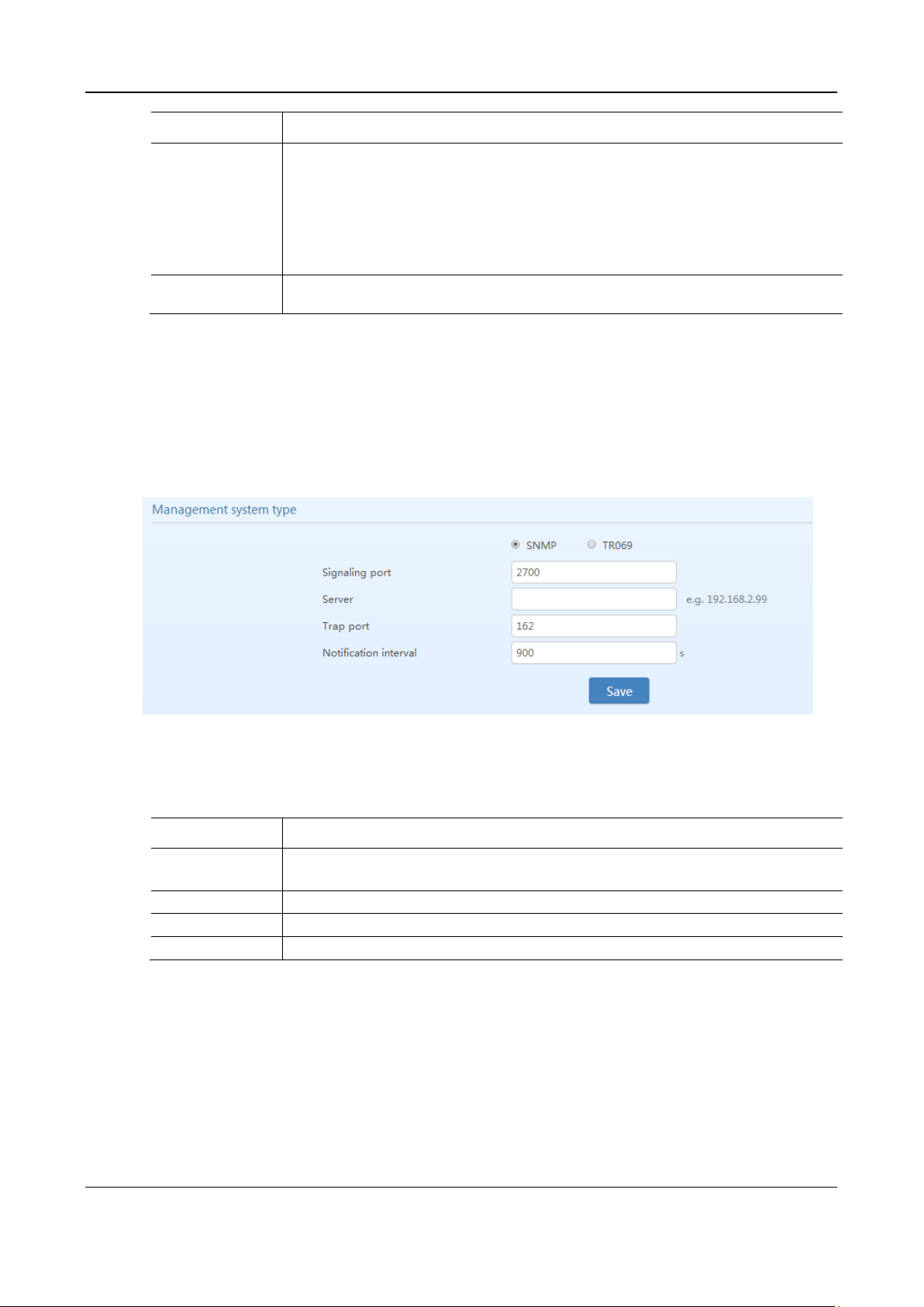
User Manual MX Series Voice Gateway
Name
Description
Update mode
The following modes are available.
Power on: the gateway detects whether there are configurations and firmware to be updated
when the device is powered on.
Power on + Periodical: when the device is powered on, the gateway first checks whether
there are configurations and firmware to be updated, and then periodically performs checking
based on the set times.
Upgrade period
When Power on + Periodical is set, this parameter specifies the interval for periodic automatic
upgrades. The default range is 3600 seconds. The value range is 5 to 84600 second.
Name
Description
Signaling port
Enter the SNMP local port. The default value is 2700.
If SNMP is selected, the following three parameters need to be specified.
Server
Enter the address of the SNMP server.
Trap port
Enter the port number of the SNMP server. The default value is 162.
Notification interval
The default value is 900 seconds.
2.6.3 Management System Type
After login, click Advanced > System to open this interface.
Figure 2-44 SNMP Configuration Interface
Table 2-25 SNMP Configuration Parameters
74 New Rock Technologies, Inc.
Page 75
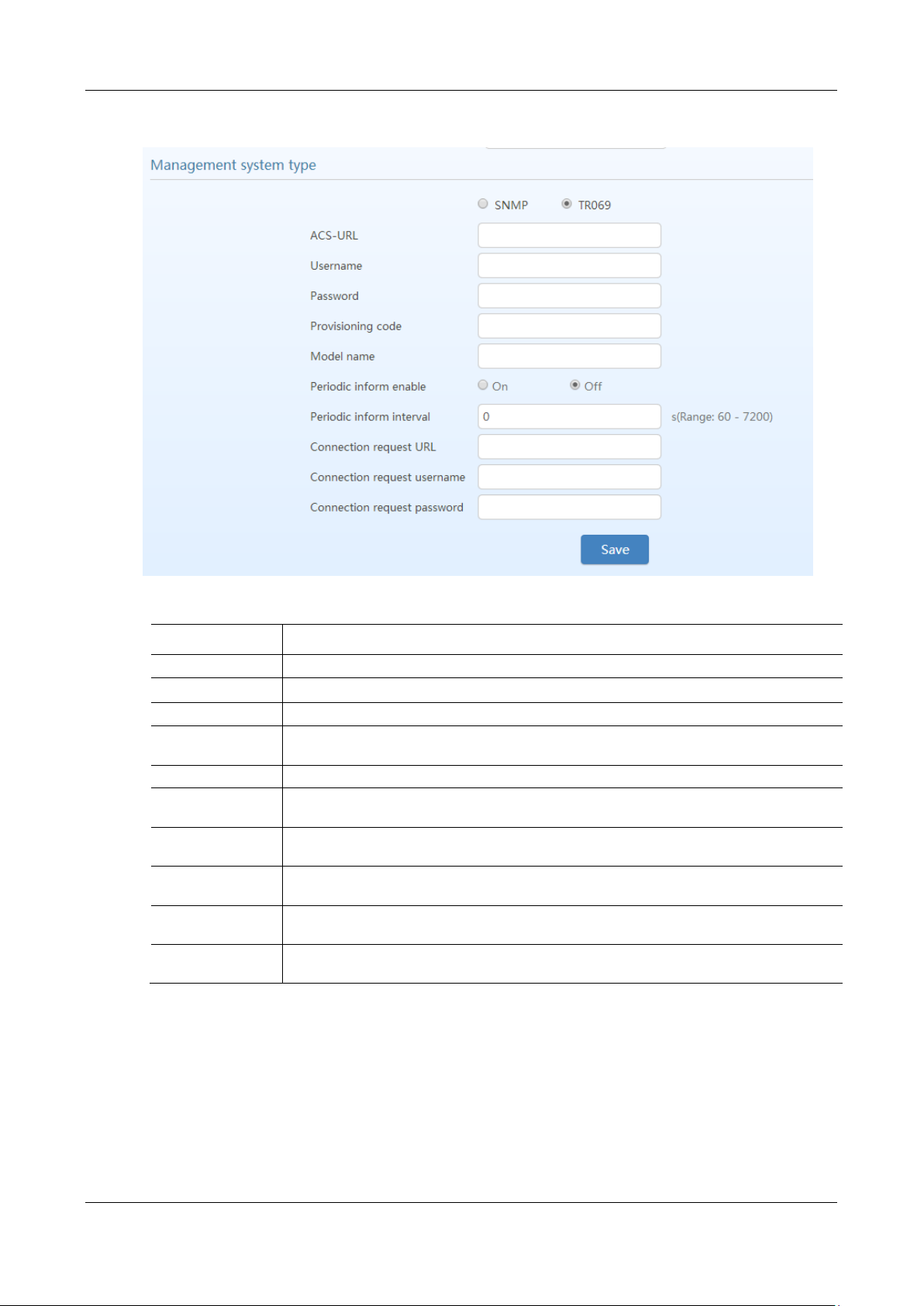
MX Series Voice Gateway User Manual
Name
Description
ACS-URL
Specify the URL of the ACS.
User name
Set the user name used by the device to authenticate with the ACS.
Password
Set the password used by the device to authenticate with the file server
Provisioning code
Information of the device vendor, which may be used to indicate the primary service provider
and other provisioning information to the ACS. It can be numbers or English letters.
Model name
A brief description of the interface type or name in the form of characters.
Periodic inform
enable
A switch used to specify whether to periodically report to the ACS.
Periodic inform
interval
The interval for reporting to the ACS.
Connection request
URL
The address used for the ACS to connect back to the device.
Connection request
username
The account used for the ACS to connect back to the device, for example, admin.
Connection request
password
The password used for the network management server to connect back to the device.
Figure 2-45 TR069 Configuration Interface
Table 2-26 TR069 Configuration Parameters
2.6.4 Certificate (Available on the HX4E/MX8A)
After login, click Advanced >Cert. to open the interface.
New Rock Technologies, Inc. 75
Page 76
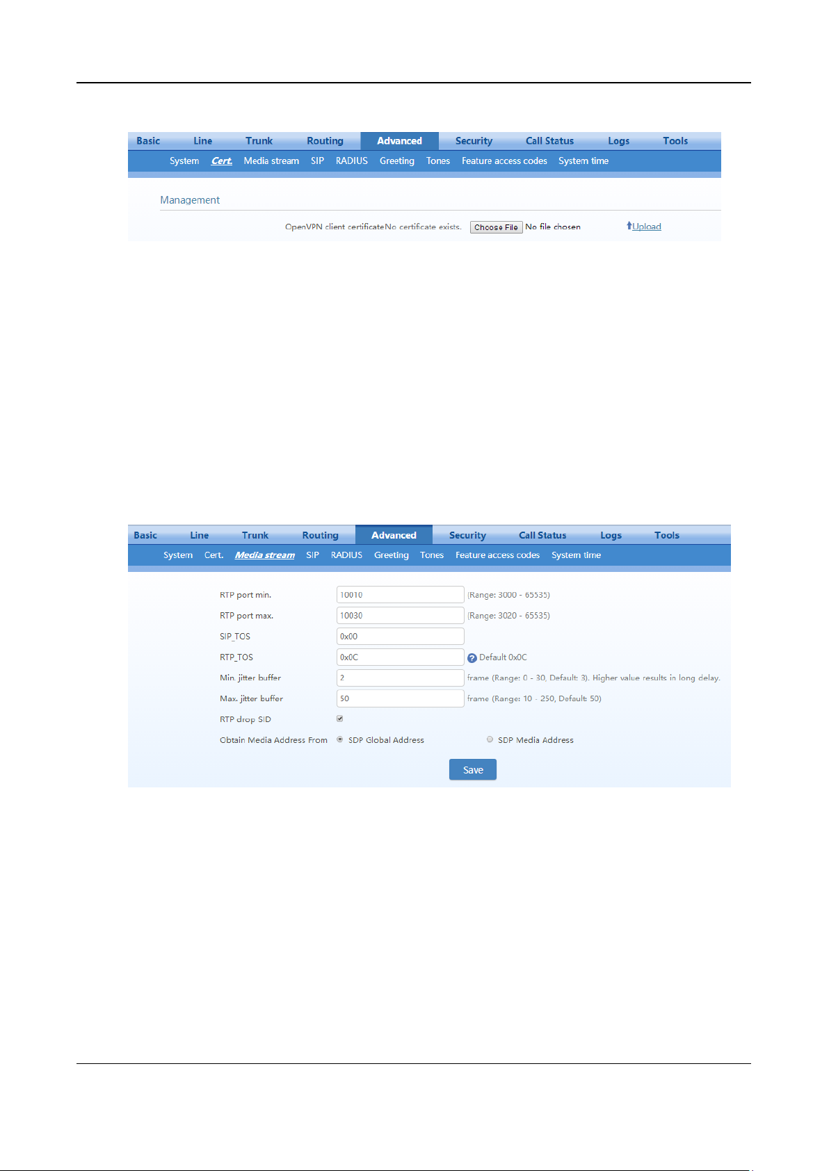
User Manual MX Series Voice Gateway
Figure 2-46 Certificate Configuration Interface
Step 1
Prepare the OpenVPN certificate file “client.vpn” based on the information provided by the
server. For details, see 4 Making an OpenVPN Client Certification.
Step 2
Step 3
Step 4
Click
Upload
Select and upload the file client.ovpn.
Reboot the device.
.
2.6.5 Media Stream
After login, click Advanced > Media Stream to open this interface.
Figure 2-47 HX4E/MX8A Media Stream Configuration Interface
76 New Rock Technologies, Inc.
Page 77
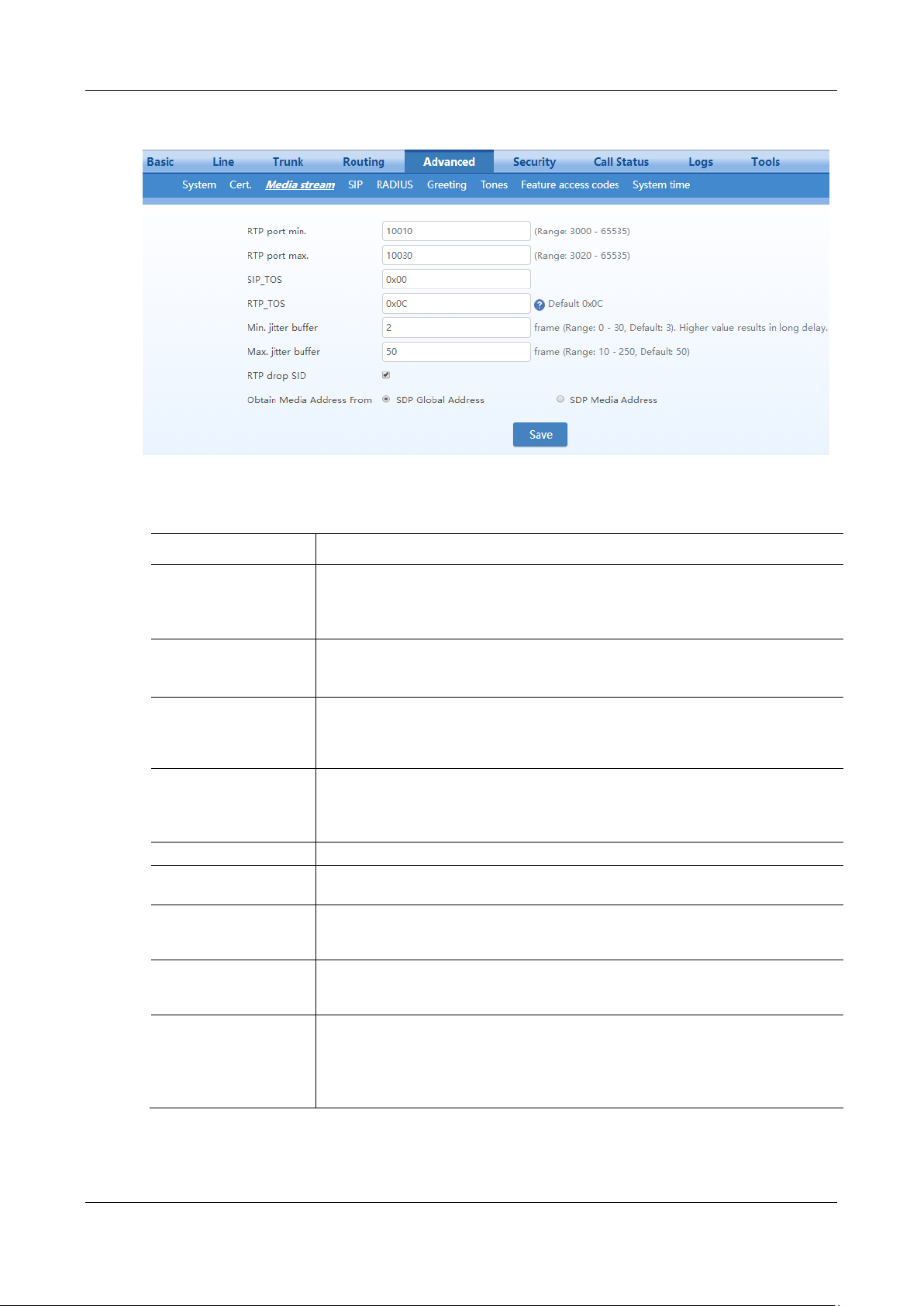
MX Series Voice Gateway User Manual
Name
Description
RTP port min.
The lowest port number of UDP ports for RTP transmission and receiving. The parameter
must be greater than or equal to 3000. This is a required field.
Note: each phone call will occupy RTP and RTCP ports. If the gateway is equipped with 4
subscriber lines (or trunk line), then at least 8 UDP ports are needed.
RTP port max.
The highest port number of UDP ports for RTP’s transmission and receiving.
This is a required field. The value must be greater than or equal to “2 × number of lines +
min. RPT port”.
iLBC payload type
(MX60/MX60E/
MX120G)
Specify the RTP payload type value of the iLBC codec in the range of 97 to 127 with the
default value 97.
The value should be consistent with that on the platform.
G.723.1 rate
(MX60/MX60E/
MX120G)
Specify the bit rate at which G.723.1 operates to either 5,300 bit/s or 6,300 bit/s. It is 6,300
bit/s by default.
SIP_TOS
For SIP signaling, set the service quality for different priorities. The default value is 0x00.
RTP_TOS
For RTP voice streams, set the service quality for different priorities. The default value is
0x0c.
Min. jitter buffer
RTP Jitter Buffer is constructed to reduce the influence brought by network jitter. This
parameter specifies the minimum number of RTP packets in the buffer. The default value
is 2 frames. The value range is 0 to 30 frames.
Max. jitter buffer
RTP Jitter Buffer is constructed to reduce the influence brought by network jitter. This
parameter specifies the maximum number of RTP packets allowed in the buffer. The
default value is 50 frames. The value range is 10 to 250 frames.
RTP drop SID
Select to discard received RTP SID voice packets. By default, SID voice packets will not
be dropped.
Note: RTP SID packets should be dropped only when they are in nonconformity to the
specifications. Nonstandard RTP SID data could generate noise for calls.
Figure 2-48 MX60/MX60E/MX120G Media Stream Configuration Interface
Table 2-27 Media Stream Configuration Parameter
New Rock Technologies, Inc. 77
Page 78
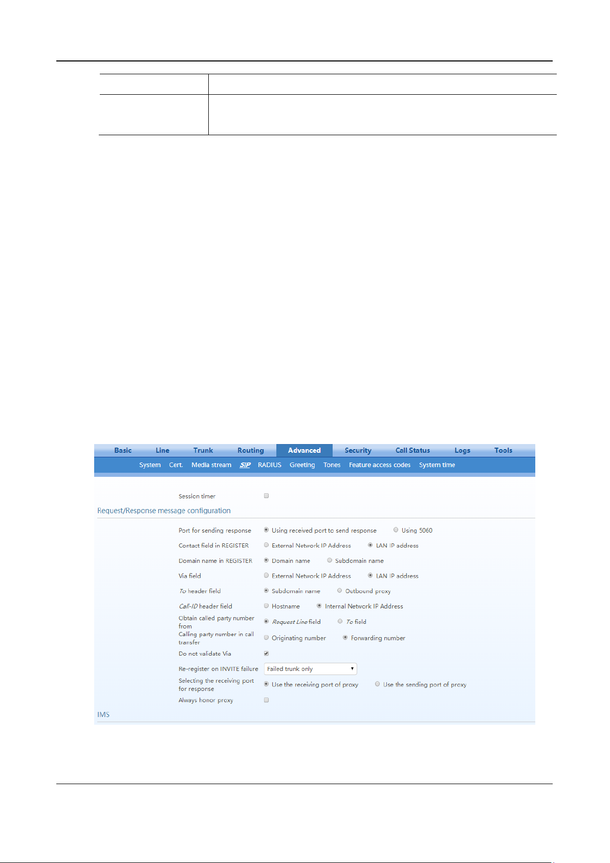
User Manual MX Series Voice Gateway
Name
Description
Obtain Media
Address From
SDP global address (default value): obtains the IP address from SDP global address;
SDP media address: obtains the IP address from SDP Media Description.
2.6.6 SIP Configuration
SIP messages consist of request messages and response messages. Both include a SIP message-header
field and SIP message-body field. The SIP message header mainly describes the message sender and
receiver; SIP message body mainly describes the specific implementation method of the dialog.
Message of request: the SIP message sent by a client to the server, for the purpose of activating the given
operation, including INVITE, ACK, BYE, CANCEL, OPTION and UPDATE etc.
Message of response: the SIP message sent by a server to the client as response to the request, including
1xx, 2xx, 3xx, 4xx, 5xx, and 6xx responses.
Message header: Call-ID.
Parameter line: Via, From, To, Contact, Csq, Content-length, Max-forward, Content-type, White Space,
and SDP etc.
MX gateways provide flexibility in field setting in order to improve compatibility with the SIP register
server.
After login, click Advanced > SIP to open this interface.
Figure 2-49 SIP Related Configuration Interface
78 New Rock Technologies, Inc.
Page 79
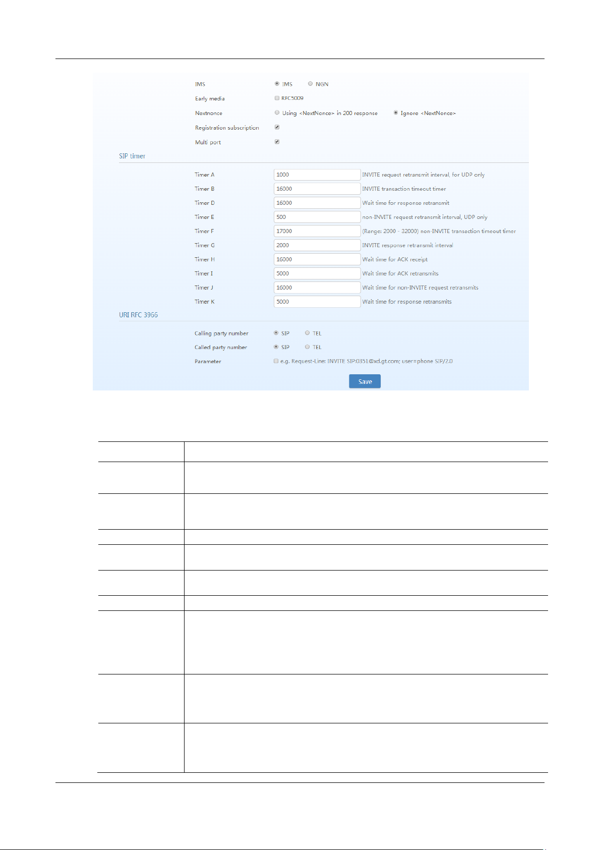
MX Series Voice Gateway User Manual
Name
Description
SIP configuration
MWI subscription
The default is 86400 seconds. Set the time interval for which MWI service subscription request
will be sent to the SIP server. This parameter should be used in conjunction with voice mail
subscription on the page of the subject subscriber line.
PRACK
Determine whether to activate Reliable Provisional Responses. (RFC 3262)
Session timer
Choose to activate session refresh (RFC 4028). By default, session timer is not activated. By
default, this is not selected.
Session interval
Set the session refresh interval that will be included in the Session-Expires field of INVITE or
UPDATE messages. Default value is 1800 seconds.
Minimum timer
Set the minimum value of session refresh interval.
Request/Response
message
configuration
Port for sending
response
Select the port for sending SIP signaling responses:
Using received port to send response
Using 5060
Contact field in
REGISTER
Select either the External network IP address or the LAN IP address.
External network IP address: use the NAT information returned by registration server.
LAN IP address: keep original content of Contact when register.
Table 2-28 SIP Related Configuration Parameter
New Rock Technologies, Inc. 79
Page 80

User Manual MX Series Voice Gateway
Name
Description
Domain name in
REGISTER
The default is Domain name.
Domain name: complete domain name used for registration (for example:
[email protected]);
Sub domain name: only use the common part of the name of domain (for example:
Via field
Choose to use External network IP address (NAT public address) or LAN IP address as the Via
header field, the default is External network IP address.
To header field
Choose whether to use Sub domain name or Outbound proxy as the To header field, the default
is Sub domain name.
Call-ID header field
Choose whether to fill Call ID field with Host name or Local IP address, the default is Internal
network IP address.
Obtain Called party
number from
Choose whether the gateway acquires the called number from Request Line field or To field.
The default is from Request line field.
Calling party
number in call
transfer
Under call forwarding, the calling party number sent can be chosen from the originating number
or the forwarding number, the default is Forwarding number.
For example: the subscriber line 2551111 on the gateway activates call forwarding feature and
sets the destination to 3224422. When caller with 13055553333 calls 2551111, the call will be
forwarded to 3224422:
If Originating number is chosen, the number 13055553333 will be sent to 3224422 as
calling party number;
If Forwarding number is chosen, the number 2551111 will be sent to 3224422 as calling
party number.
Do not validate Via
Set to ignore Via field, By default, Via is ignored.
Re-register on
INVITE failure
Set to activate registration of all trunks or only failed trunks upon timeout of INVITE message.
By default, it is disabled.
Selecting the
receiving port for
response
Select either the receiving port of proxy or the sending port of proxy.
Always honor proxy
If this is selected, the SIP messages will always go through the SIP proxy server configured on
Basic > SIP page.
IMS
IMS
Select either the IMS mode or the NGN mode.
Early media
Enable RFC5009. It is not enabled by default.
Media direction
attribute
Set parameter values of the P-Early-Media header field:
Supported
Sendrecv
Sendonly
Recvonly
Inactive
The fields vary according to the type of SIP message. They should be set as required by the peer
end.
Note: This parameter can be configured after Early media is selected.
Nextnonce
Select to carry “nextnonce” in 200 OK message or ignore “nextnonce”.
Registration
subscription
Select to subscribe registration status.
Multi port
A local SIP port can be assigned to each line.
SIP timer
Timer A
INVITE request retransmit interval, for UDP only. It is 1000 ms by default.
Timer B
INVITE transaction timeout timer. It is 16000 ms by default.
Timer D
Wait time for response retransmits. It is 16000 ms by default.
80 New Rock Technologies, Inc.
Page 81
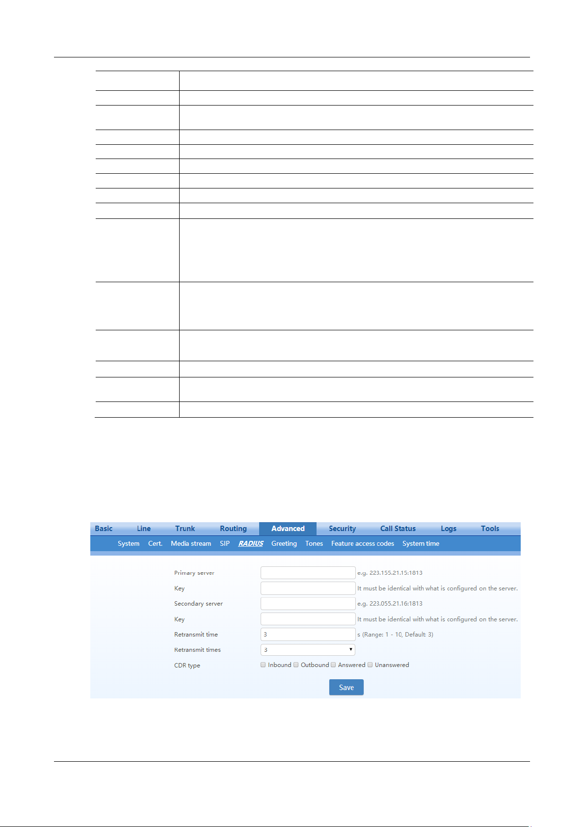
MX Series Voice Gateway User Manual
Name
Description
Timer E
non-INVITE request retransmit interval, UDP only. It is 500 ms by default.
Timer F
non-INVITE transaction timeout timer. It is 17000 ms by default and ranges from 2000 to 32000
ms.
Timer G
INVITE response retransmit interval. It is 2000 ms by default.
Timer H
Wait time for ACK receipt. It is 16000 ms by default.
Timer I
Wait time for ACK retransmits. It is 5000 ms by default.
Timer J
Wait time for non-INVITE request retransmission. It is 16000 ms by default.
Timer K
Wait time for response retransmission. It is 5000 ms by default.
URI RFC 3966
Calling party
number
Select the address scheme for calling party:
SIP: SIP URI is used, for example
“From: <sip:[email protected]>;tag=143349062153-1”.
TEL: tel URL is used, such as “From: <tel:212>;tag=143349065857-1”.
Called party number
Select the address scheme for called party:
SIP: SIP URI is used, for example “To: <sip:[email protected]>”.
TEL: tel URI is used, for example “To: <tel:212>”.
user=phone
Parameter
Places the user=phone field in front of the SIP version in the INVITE request.
e.g. INVITE sip:[email protected];user=phone SIP/2.0
TCP
This parameter is only available on the OCS gateway (for example, the MX8A-OCS).
Protocol type
Select SIP/TCP or SIP/UDP, and the default is UDP. Note: both peers must choose the same
transmission type.
Local TCP port
Specify the local port used by SIP/TCP.
2.6.7 RADIUS (Unavailable on the HX4E)
After login, click Advanced >RADIUS to open this interface.
Figure 2-50 RADIUS Configuration Interface
New Rock Technologies, Inc. 81
Page 82
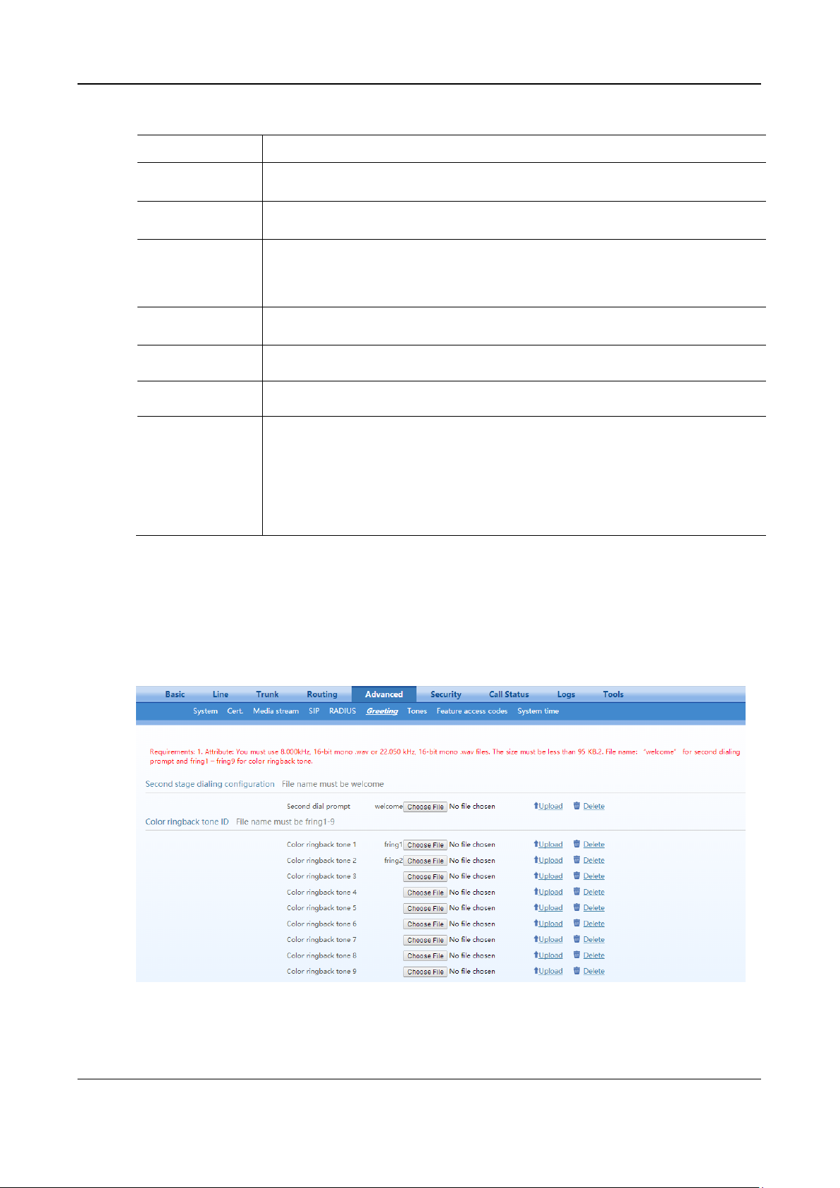
User Manual MX Series Voice Gateway
Name
Description
Primary Server
Define IP address and port number of preferred Radius server.
Note: if the port number is not yet configured, please use Radius default port number 1813.
Key
Set the share key to be used for encrypted communications between Radius client and server.
Note: The share key should be configured the same for both client and server side.
Secondary Server
Set the IP address and port number of standby Radius server. When an error occurs in
communications between gateway and preferred Radius server, the gateway will automatically
activate standby Radius server.
Note: In case of no configuration of port number, use default port number of 1813.
Key
The share key for communications between Radius client and standby Radius server.
Note: The key should be configured the same for both client and server side
Retransmit timer
Set the overtime on response after transmission of Radius message, the default is 3 seconds.
The retransmission will be performed If no response is given after the timeout.
Retransmit times
Set the times of retransmission of Radius message when no response is received. Default is 3
times.
CDR type
Set whether to send RADIUS charge message for
Outbound calls
Inbound calls
When calls are connected
Unanswered calls
Table 2-29 RADIUS Configuration Parameter
2.6.8 Greeting
After login, click Advanced>Greeting to open the audio files interface.
Figure 2-51 Greeting Interface
82 New Rock Technologies, Inc.
Page 83
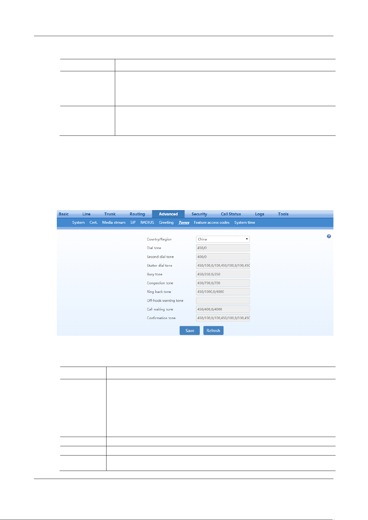
MX Series Voice Gateway User Manual
Name
Description
Second Stage
Dialing
Configuration(Appl
icable for FXO
port)
Click Browse, and then select the local audio file named welcome.wav. Click Upload. The
uploaded audio file overwrites the original one.
If you want to delete the current customized second stage dialing tone, click Delete. After the
gateway restarts, the default second stage dialing tone will be used.
CRBT ID
Click Browse, and then select the local audio file named fring1/2/3/4/5/6/7/8/9.wav. Click
Upload. The uploaded audio file overwrites the original one.
If you want to delete the current color ringback tone, you can click Delete. After the gateway
restarts, the default color ringback tone will be used.
Name
Description
Country/Region
There are progress tone plans for several countries and regions that are pre-programmed in
gateways. Users may also specify the tone plan according to the national standard. Gateways
provide tone plans for the following countries and regions:
China, the United States, France, Italy, Germany, Mexico, Chile, Russia, Japan, South Korea, Hong
Kong, Taiwan, India, Sudan, Iran, Algeria, Pakistan, Philippines, Kazakhstan, Singapore, Israel,
Malaysia, Indonesia, United Arab Emirates, Zimbabwe, Australia.
User-defined: define the call progress tones by yourself.
Dial tone
Prompt tone of off-hook dial tone.
Second dial tone
Second stage dial tone.
Stutter dial tone
Prompt of voice mail, or when the subscriber line is set with “Do not Disturb Service and Call
Transfer”.
Table 2-30 Greeting Configuration Parameters
2.6.9 Call Progress Tone Plan
After login, click Advanced > Tones to open this interface.
Figure 2-52 Call Progress Tone Configuration Interface
Table 2-31 Call Progress Tone Configuration Parameters
New Rock Technologies, Inc. 83
Page 84

User Manual MX Series Voice Gateway
Name
Description
Busy tone
Busy line prompt.
Congestion tone
Notification of call set up failure due to resource limit.
Ring back tone
The tone sent to caller when ringing is on.
Off-hook
warning tone
Reminds the subscriber when the phone is off-hook and no dialup has occurred.
Call waiting tone
Prompt the subscriber that another caller is attempting to call.
Confirmation
tone
Confirms feature codes are being entered.
Here are examples that illustrate the various call-progress tones
350+440 (dial tone)
Indicates the dual–frequency tone consisting of 350 and 440 Hz
480+620/500,0/500 (busy)
Indicates the dual–frequency tone consisting of 480 and 620 Hz, repeated playing with 500
milliseconds on and 500 milliseconds off.
Note: 0/500 indicates 500 milliseconds mute.
440/300,0/10000,440/300,0/10000
Indicate a 440 Hz single frequency tone, repeated twice in the cadence of 300 milliseconds on and 10
seconds off.
950/333,1400/333,1800/333,0/1000
Indicate the repeated playing of 333 milliseconds of 950 Hz, 333 milliseconds of 1400 Hz, 333
milliseconds of 1800 Hz, and mute of 1 second.
2.6.10 Feature Access Codes
The feature codes consist of system feature codes and service feature codes. The system feature codes are
used for acquiring gateway information, and the latter is used for users to activate and deactivate
supplementary services.
After login, click Advanced > Feature access codes to open this interface.
The following are the examples of the dialing rule for the feature codes:
Using *xx (dial * and 2 digits number) to activate a service
Using #xx (dial # and 2 digits number) to cancel a service.
This is illustrated with the following defaults for various parameters, which may be modified according to
requirements.
It is highly recommended not to modify the default configuration in System feature codes.
84 New Rock Technologies, Inc.
Page 85
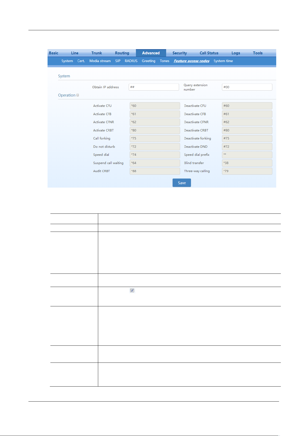
MX Series Voice Gateway User Manual
Name
Description
System feature codes
Obtain IP address
The feature code for obtaining the IP address of gateway, with a default of ##.
When this feature code is dialed, the phone will play the device IP address, the web port
number for accessing the device, the IP address of the gateway, the subnet mask, and the
system software version number.
Note: If the device has only the FXO port, you can use Finder, a tool developed by New Rock,
to obtain the IP address.
If you want to have a copy of Finder, please send an email to [email protected].
Query extension
number
The feature code for obtaining the phone number of the subscriber line, with default of #00. By
dialing this key, you will hear the phone number of the subscriber line voiced by the gateway.
Service feature codes
You can click to allow the change of the service feature codes, or deselect the checkbox
to not allow the change of the service feature code. By default, service feature codes are not
allowed to change.
Activate CFU
The feature code for activating unconditional call forwarding, with a default of *60. Dialing
this key will activate unconditional call forward of the line and set the destination number for
call forwarding. User operation: off hook → press *60 →enter the destination number.
Users can determine the latest destination number set by dialing *60*.
Note: It is required to enable call forwarding service before using this function (please see the
instructions on the relevant configuration of subscriber line).
Deactivate CFU
The feature code for deactivating unconditional call forwarding, with default of #60.
User operation: off hook → press #60 → hang up.
Activate CFB
The feature code for activating call forwarding when the line is busy, with default of *61.
Dialing this key may activate CFB, and specify the destination number. It is required to enable
call forwarding on busy service before using this function (See 2.3.2 Subscriber Line
Features).
Figure 2-53 Feature Codes Configuration Interface
Table 2-32 Feature Codes Configuration Parameter
New Rock Technologies, Inc. 85
Page 86

User Manual MX Series Voice Gateway
Name
Description
Deactivate CFB
The feature code for deactivating call forwarding on busy, with default of #61.
User operation: off hook → press #61 → hang up.
Activate CFNR
The feature code for activating call forwarding on no answer, with default of *62. Dialing the
feature code should activate call forwarding on no answer and specify destination number.
Note: It is required to enable call forwarding on no answer service before using this function
(See 2.3.2 Subscriber Line Features).
Deactivate CFNR
The feature code for deactivating call forwarding on no answer, with default of #62.
Activate CRBT
The feature code for activating color ringback tone, with default of *80. Subscribers may
select their favorite color RB tone by using this key.
Note: It is required to start color ring service before using this function (See 2.3.2 Subscriber
Line Features for how to assign the feature to the phone).
User operation: upon off hook, the subscriber may press the feature code (*80 by default), then
input the two-digit index numbers of color ring.
Dial *80* to listen to the color ring that has been previously set.
Deactivate CRBT
The feature code for deactivating the color ring, with default of #80. The subscriber may use
such key to recover the normal ring of phone.
User operation: off hook → press #80 → hang up.
Call Forking
The feature code for activating the double-ring/forking feature, with default of *75.
Deactivate forking
The feature code for deactivating the feature, with default of #75.
Do not disturb
Activate do not disturb (DND), with default of *72. With DND selected, the gateway will
reject all coming calls by sending busy tone to the callers.
Note: It is required to start DND prior to using this function (See 2.3.2 Subscriber Line
Features).
Deactivate DND
The feature code to cancel DND, with default of #72. Dialing the feature code may recover
normal ringing upon the arrival of incoming calls.
Speed dial
Define the feature code of dial, with default of *74. This key allows the user to build a table of
2-digits (20~49) speed-dial numbers.
Note: It is necessary to get the dial-up service under way before applying this function (please
see Phone for instructions on assigning the feature to the phone).
User operation: upon dialing the feature code (*74), dial the two-digit speed dial followed by
the expanded number terminated with #.
Speed dial prefix
The prefix number for applying abbreviated dialing, with default of **. The prefix should be
added in front of abbreviated dialing numbers when using abbreviated dialing.
User operation: off hook → dial the prefix number of abbreviated dialing (**) and dial
abbreviated dialing number (20).
Suspend call waiting
The feature code for cancelling the call waiting feature for next call, with default of *64.
Dialing this feature code will temporarily disable the call waiting function for the next phone
call.
Note: The feature code works only for single cancel, to cancel the call waiting complete,
please refer to Table 2-14 about configuration of subscriber line.
Blind call transfer
The feature code of blind call transfer, with default of *38.
User operation: during the call, tap the phone hook switch or press R button→ dial *38→ dial
the called number and then hang up.
Audit CRBT
The feature code for listening to the color ring, with default of *88.
User operation: off hook → press *88 → input color ring number.
While listening, you can press a two-digit CRBT index to change to another CRBT file.
Three-way calling
The default value is *79.
86 New Rock Technologies, Inc.
Page 87
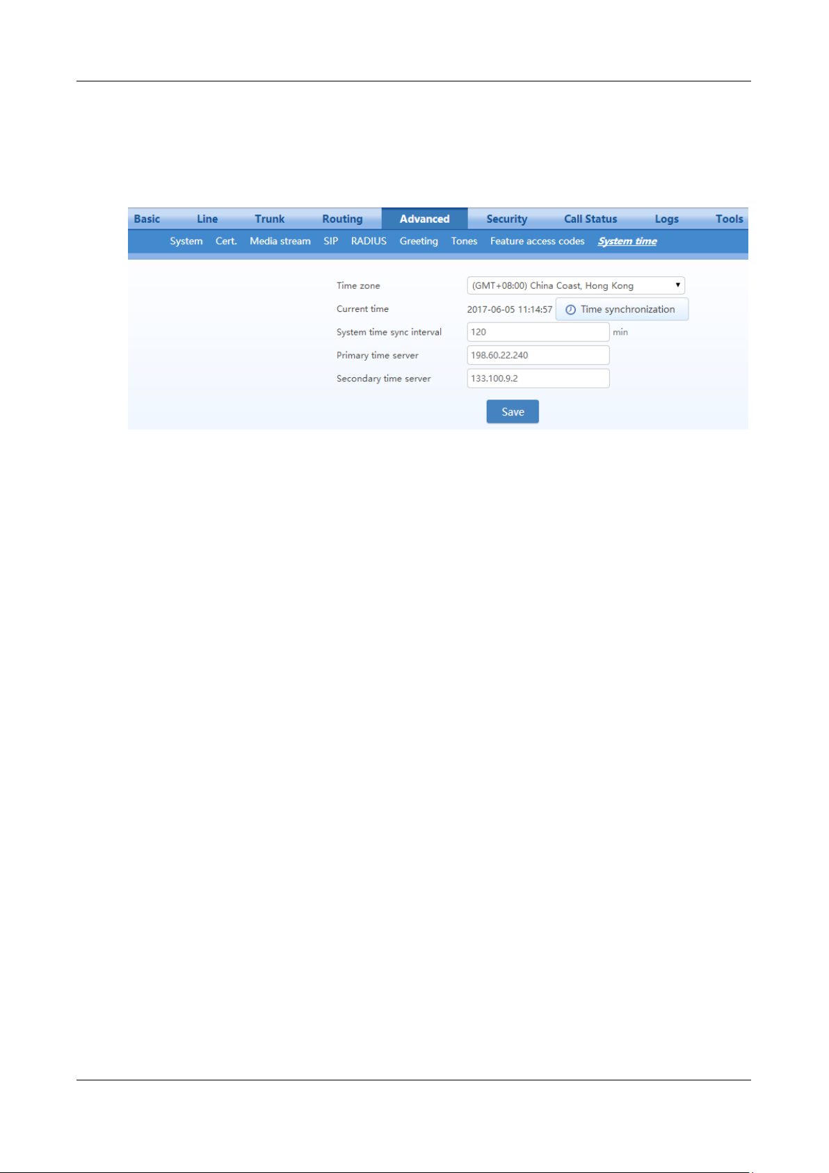
MX Series Voice Gateway User Manual
2.6.11 Clock Service
After login, click Advanced > System time to open this interface.
Figure 2-54 Clock Service Interface
New Rock Technologies, Inc. 87
Page 88

User Manual MX Series Voice Gateway
Name
Description
Time Zone
Select a time zone, the parameter values include:
(GMT-11:00) Midway Island
(GMT-10:00) Honolulu. Hawaii
(GMT-09:00) Anchorage, Alaska
(GMT-08:00) Tijuana
(GMT-06:00) Denver
(GMT-06:00) Mexico City
(GMT-05:00) Indianapolis
(GMT-04:00) Glace_Bay
(GMT-04:00) South Georgia
(GMT-03:30) Newfoundland
(GMT-03:00) Buenos Aires
(GMT-02:00) Cape_Verde
(GMT) London
(GMT+01:00) Amsterdam
(GMT+02:00) Cairo
(GMT+02:00) Israel
(GMT+02:00) Zimbabwe
(GMT+03:00) Moscow
(GMT+03:30) Teheran
(GMT+04:00) Muscat
(GMT+04:00) United Arab Emirates
(GMT+04:30) Kabul
(GMT+05:30) Calcutta
(GMT+05:00) Karachi
(GMT+06:00) Almaty
(GMT+07:00) Bangkok
(GMT+07:00) Indonesia
(GMT+08:00) Beijing
(GMT+08:00) Taipei
(GMT+08:00) Singapore
(GMT+08:00) Malaysia
(GMT+09:00) Tokyo
(GMT+10:00) Canberra
(GMT+10:00) Adelaide
(GMT+11:00) Magadan
(GMT+12:00) Auckland
Current time
Display current time for the device. Click Clock calibration to calibrate the time.
System time sync
interval
Set the synchronization period of the time. It is 120 minutes by default.
Primary time server
Enter the IP address of preferred time server here. It has no default value.
Table 2-33 Clock Service Parameters
88 New Rock Technologies, Inc.
Page 89

MX Series Voice Gateway User Manual
Name
Description
Secondary time
server
Enter the IP address of Secondary time server here. It has no default value.
2.7 Security
2.7.1 Access Security
The administrator is recommended to perform the following operations to prevent mostly illegal accessing
to the device:
Regularly change the admin/operator password for accessing Web GUI
Regularly change the root/operator password for accessing the device through SSH, and improve the password
strength
Regularly change the HTTP/HTTPS/SSH port for accessing the device
Disable SSH once accessing is completed.
All of the above are available on Security>Access page.
New Rock Technologies, Inc. 89
Page 90
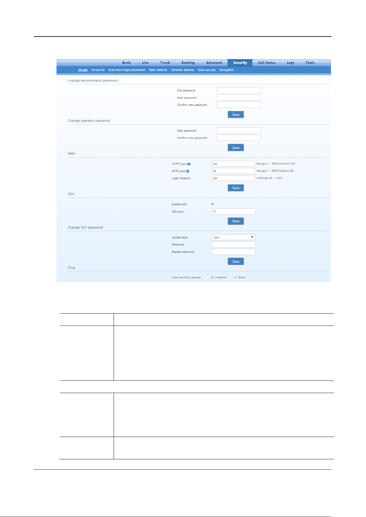
User Manual MX Series Voice Gateway
Name
Description
Change
administrator
/operator password
Set the administrator/operator password by entering the current password.
The password must meet the following requirements:
8 to 16 characters
At least two of the following: letters, numbers, and symbols
Excluding&, =, and “
Please change the initial password at first time login.
Web
HTTP/HTTPS port
Set the HTTP/HTTPS port for the device. The default value is 80 for HTTP and 443 for
HTTPS.
HTTP/HTTPS port is use for:
Web accessing (XML command interface)
Auto Provisioning
Login time out
Set the login timeout interval, the default value is 600s.If you do not conduct any
operation within timeout interval, you will log out.
Figure 2-55 Access Configuration Interface
Table 2-34 Access security setting parameters
90 New Rock Technologies, Inc.
Page 91
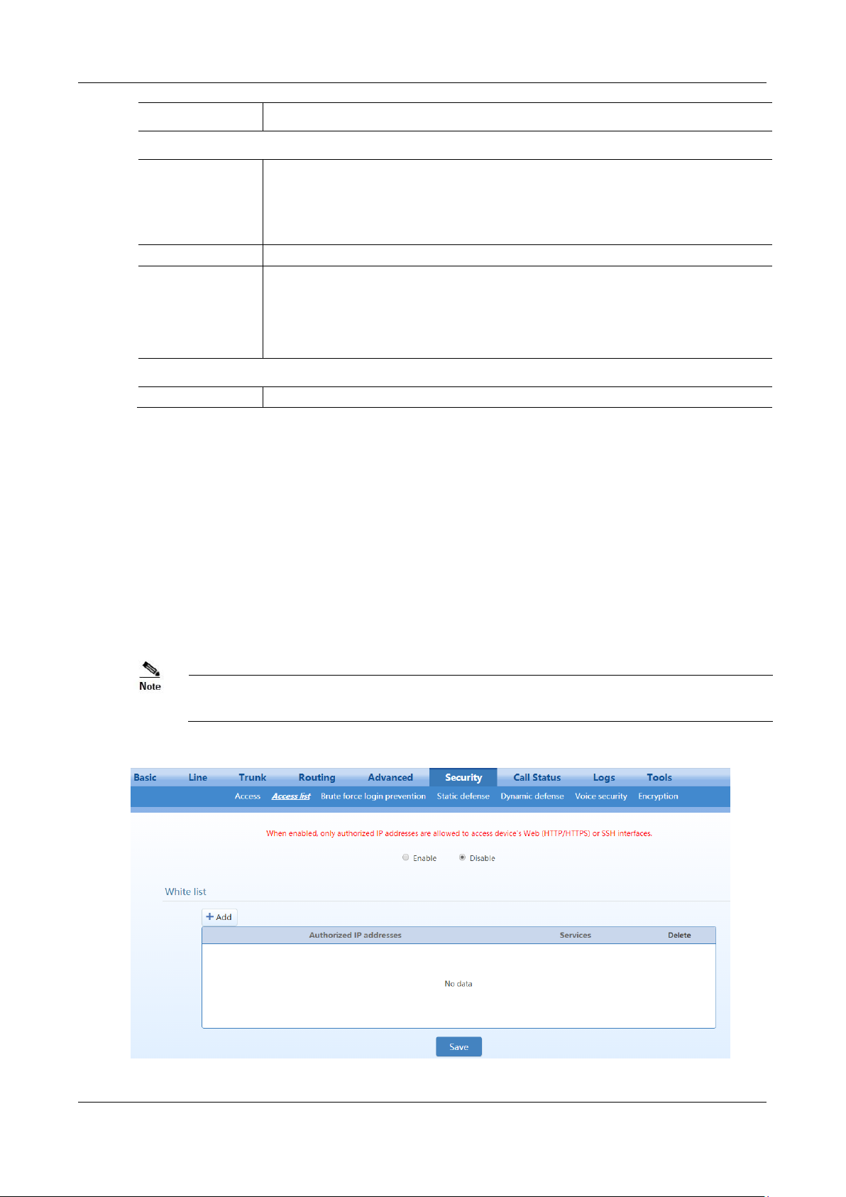
MX Series Voice Gateway User Manual
Name
Description
SSH
Enable SSH
If this parameter is selected, terminals are allowed to access the device through SSH. It is not
selected by default.
When accessing the device through SSH, you should login with user operator, and use su root
command to change to user root.
Please disable SSH in time after accessing is finished.
SSH port
Set the SSH port for the device. The default value is 22.
Change SSH
password
Set password of user root or operator. Password must meet the following requirements:
6 to 20 characters
At least the two of following: English letters, numbers, and symbols
Excluding & = “
Ping
Inbound Ping request
Block or unblock the Ping requests. The device block the ping requests by default.
Once access list is enabled, only addresses specified here are allowed to access the device through Web GUI
or SSH.
2.7.2 Access list
Access list is used to specify the source addresses which are allowed to access the device through Web GUI
(HTTP/HTTPS) or SSH.
After login, click Security>Access list to open the configuration interface.
Figure 2-56 Access list configuration Interface
New Rock Technologies, Inc. 91
Page 92

User Manual MX Series Voice Gateway
If SSH is selected, please enable SSH on Security>Access page.
The device allows an access list of up to 20 entries.
Click
Step 1
In the input box, enter IP addresses and select types of service.
Step 2
Select
Step 3
.
Add
Enable
, and click
Save
.
92 New Rock Technologies, Inc.
Page 93
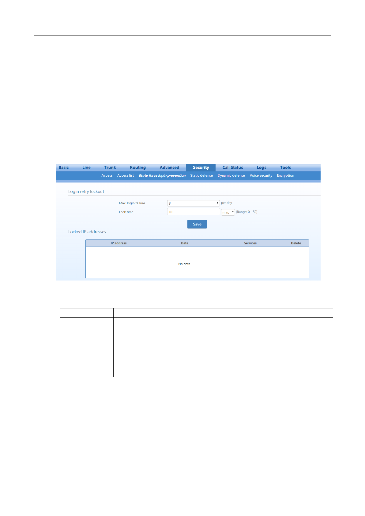
MX Series Voice Gateway User Manual
Name
Description
Max. login failure
Specify the maximum number of login failures allowed for a source IP address from which
login attempts are made to the Web GUI or SSH in a day. The IP addresses whose login
attempts exceeding the specified limit will be added to the locked list.
Value range: 1–5 times/day
Default value: 3 times/day
Lock time
Specify the IP address lock time. An IP address will be unlocked after the lock time and is
allowed to access the device again.
Default value: 10 minutes
2.7.3 Brute Force Login Prevention
A brute force login attack makes multiple login attempts within a short time period, trying to guess the
password to login.
To prevent brute force login attacks, the MX provides several methods including CAPTCHA for logging
into Web GUI, limiting the number of login attempts, and access whitelist of trusted IP addresses.
Login Retry Lockout Configuration
After a specified number of login attempts within a specified time, the source IP address of the accessor
will be blocked.
After login, choose Security > Brute force login prevention, to go to the configuration interface.
Figure 2-57 Brute Force Login Prevention (Login Retry Lockout) Configuration Interface
Table 2-35 Login Retry Lockout Parameters
Locked IP addresses
New Rock Technologies, Inc. 93
Page 94
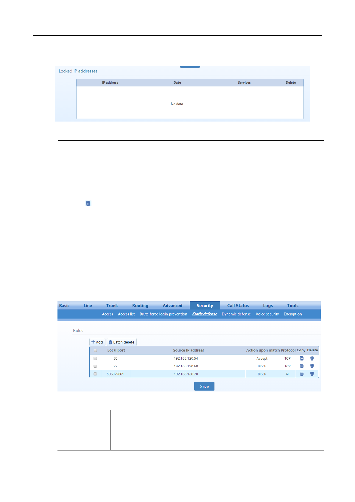
User Manual MX Series Voice Gateway
Name
Description
IP address
Indicates a locked IP address.
Date
Indicates the date when an IP address is locked.
Services
Indicates the login method of the locked IP address (Web or SSH).
Name
Description
Accept/Block
Specify whether to receive or block data packets when the specified conditions are matched
(source IP address, local port, protocol).
Local port
Specify the local port range of the device for receiving data packets.
Range is 0 to 65535.
Figure 2-58 Brute Force Login Prevention (Lockout IP Addresses) Interface
Table 2-36 Brute Force Login Prevention (Lockout IP Addresses) Information
You may perform the following maintenance operation:
Delete : Remove the IP address from the locked list.
2.7.4 ACL-based Traffic Filtering
Access Control List (ACL) based filtering provides predictable traffic filtering. You can configure filtering
rules to allow or deny receiving packets from specified IP addresses to certain ports on the device. For
example, if a remote host (with the IP address x.x.x.x) allowed to connect to a certain service using port X,
create an ACCEPT rule to allow traffic from IP x.x.x.x destined to port X on MX.
After login, choose Security > Static defense to go to the configuration interface.
Figure 2-59 Static Defense Configuration Interface
Table 2-37 Static Defense Configuration Parameters
94 New Rock Technologies, Inc.
Page 95
MX Series Voice Gateway User Manual
Name
Description
Source IP address
Specify the source IP address range.
Note: This parameter does not support domain names.
Protocol
Specify the protocol type.
The value can be set TCP, UDP, ICMP, or any.
The static defense rules take effect from top to bottom.
You may do the following operations:
Add: Add a new rule
Copy : Duplicate the selected rule to a new rule
Delete : Delete the selected rule
Batch delete: Delete all selected rules in batch
Examples
Explanations of the rules listed in Figure 2-59 are as follows:
Rule 1: Port 80 of the device is allowed to receive TCP data packets from the source IP address 192.168.120.54.
Rule 2: Port 22 of the device is prohibited from receiving TCP data packets from the source IP address
192.168.120.54.
Rule 3: Ports 5060 and 5061 of the device are prohibited from receiving data packets (of any protocol type) from
the source IP address 192.168.120.54.
2.7.5 Packet Rate Limiting Based Dynamic Blacklisting
Packet rate limiting based dynamic blacklisting enables the device to defend against Dos/DDoS attacks
which involve multiple computers all over the world and amounts of traffic.
You can set multiple defense rules.
When the rate at which the data packets received by the device exceeds the threshold preset in the rules,
the received data packets are discarded, and moreover the IP address of the attack source is added to the
blocked list. Data packets from this address will no longer be received.
Rule configuration
After login, choose Security > Dynamic defense, to go to the configuration interface.
New Rock Technologies, Inc. 95
Page 96
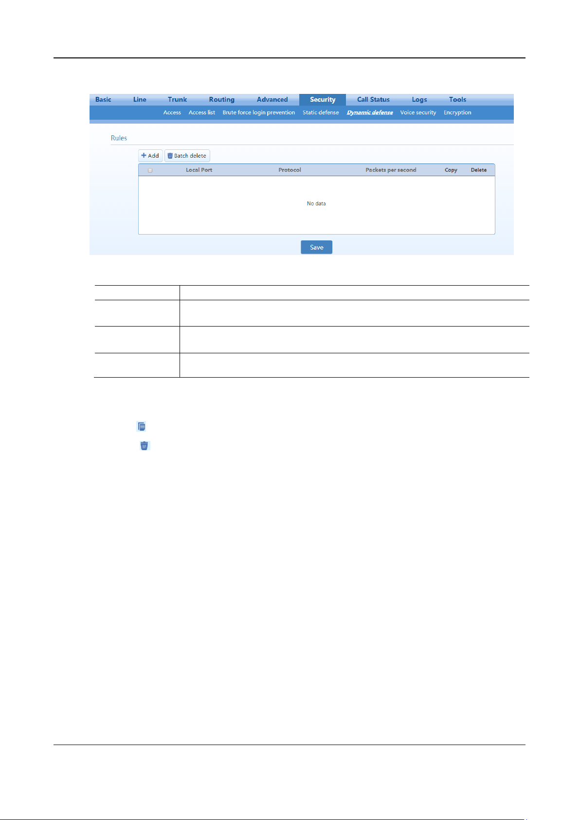
User Manual MX Series Voice Gateway
Name
Description
Local port
Specifies the local port range of the device for receiving data packets.
The supported port range is 0 to 65535.
Protocol
Specifies the protocol type.
The value can be set TCP, UDP, or any.
Packets per second
Specifies the maximum data packet rate allowed for a local port. If the data packet receiving rate
exceeds this value, the IP address of the attack source is added to the blocked IP addresses.
Figure 2-60 Dynamic Defense Configuration Interface
Table 2-38 Dynamic Defense (Rule Configuration) Parameters
You may do the following operations:
Add: Add a new rule
Copy : Duplicate the selected rule to a new rule
Delete : Delete the selected rule
Batch delete: Batch Delete all selected rules
Blocked IP addresses
The blocked IP addresses of dynamic defense will be deleted after the device reboots.
96 New Rock Technologies, Inc.
Page 97
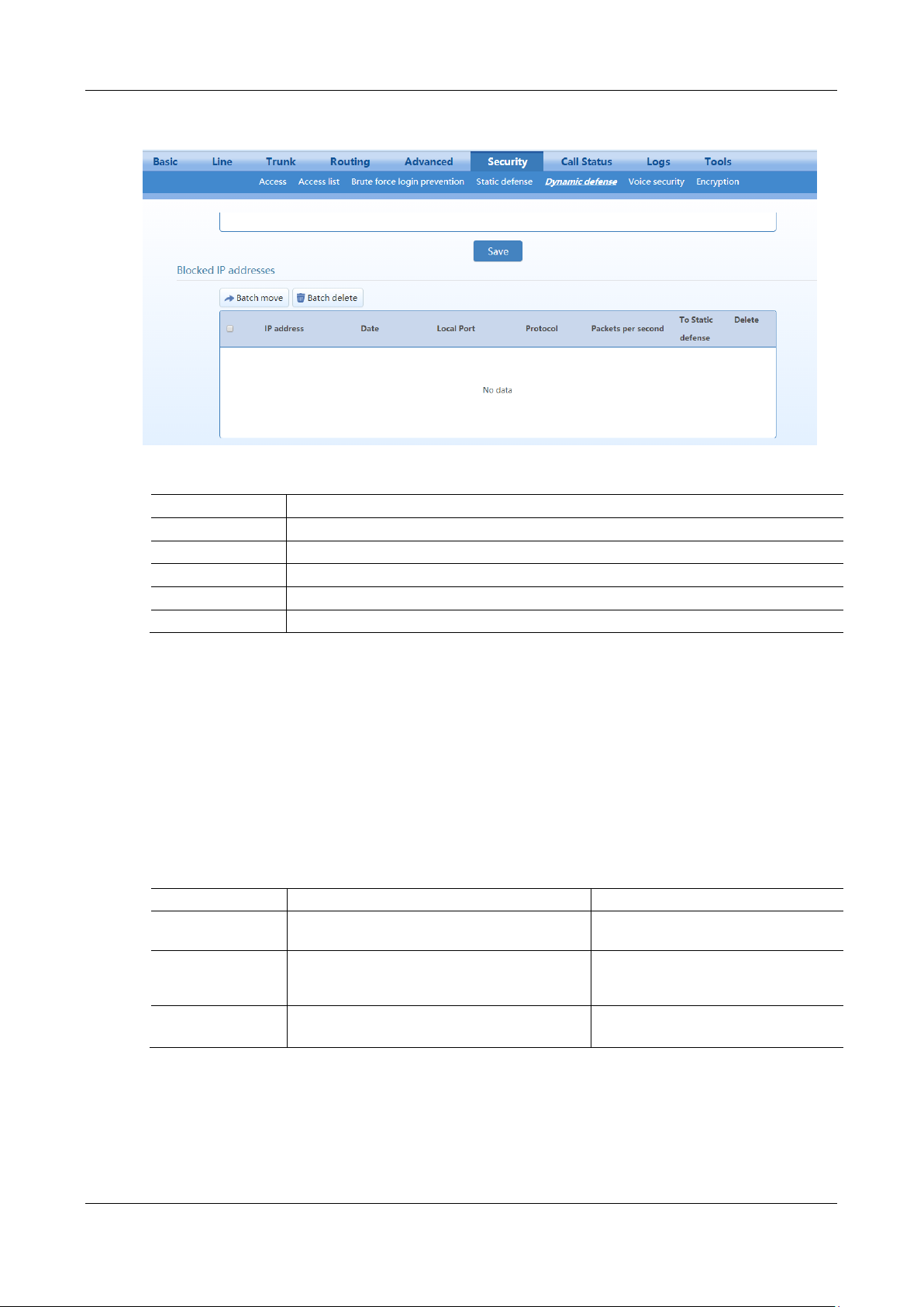
MX Series Voice Gateway User Manual
Name
Description
IP address
The IP address of the attacker detected by the device.
Date
The time when the device detects the attacker and initiates defense.
Local port
The port through which the data packet from the attacker is received.
Protocol
The protocol type.
Packets per second
The data packet receiving rate threshold.
Handling Method
Description
Applicable Scenario
Block
Add the entry to the static defense list and block
the matched packets.
These entries are confirmed to be attach
sources.
Accept
Add the entry to the static defense list and accept
the matched packets.
These entries are confirmed to be valid
sources (applicable to heavy traffic
scenarios such as call centers).
Cancel
Cancel to add the entry to the static defense list.
/
Figure 2-61 Dynamic Defense (Blocked IP Addresses) Interface
Table 2-39 Dynamic Defense (Blocked IP Addresses) Information
You can perform the following operations:
Batch move: Move the selected entries in batch to the static defense rules, and provides three subsequent choices:
Block: Add the entry to the static defense list and block the matched packets.
Accept: Add the entry to the static defense list and accept the matched packets.
Cancel: Cancel to add the entry to the static defense list.
Table 2-40 Subsequent choices for moving the Blocked IP Addresses to static defense
For details about static defense, see 2.7.4 ACL-based Traffic Filtering.
Batch delete: Delete selected entries in a batch.
Example
Explanations of the rules listed in Figure 2-60 are as follows:
New Rock Technologies, Inc. 97
Page 98
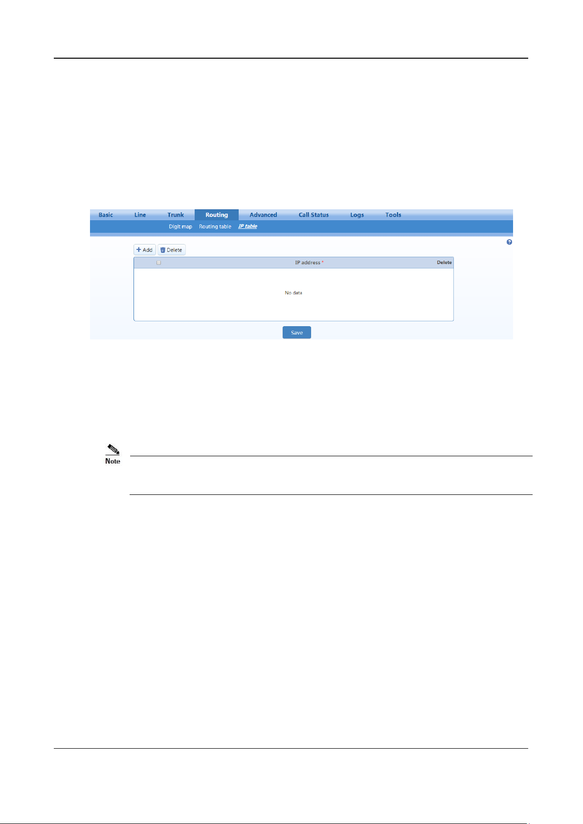
User Manual MX Series Voice Gateway
If the gateway is deployed in a public network, you are advised to set IP filtering to prevent
call theft.
Rule 1: Port 5060 is allowed to receive at most 20 UDP packets per second.
Rule 2: Port 5060 is allowed to receive at most 50 TCP packets per second.
2.7.6 IP Table
The IP filtering function is used to ignore the VoIP messages from untrusted network.
After login, click Routing > IP Table to open the configuration interface.
Figure 2-62 IP Table Configuration Interface
Add the authorized IP addresses to this table, the gateways will only process the VoIP signaling from
authorized IP addresses. If the IP table is empty, the gateways will not perform IP address-based message
filtering.
2.7.7 Voice Security
When the device is deployed in Internet, it is possible to suffer from toll fraud. But you can configure the
SIP-allowed IP address for the device to prevent toll fraud.
After login, go to Security>Voice Security to add the SIP-allowed addresses (IP addresses or domain
names).
You may add SIP servers addresses or SBC (when register to SBC) addressed to SIP-allowed addresses.
If no SIP-allowed addresses are set, the device will respond SIP signaling from any IP address.
98 New Rock Technologies, Inc.
Page 99
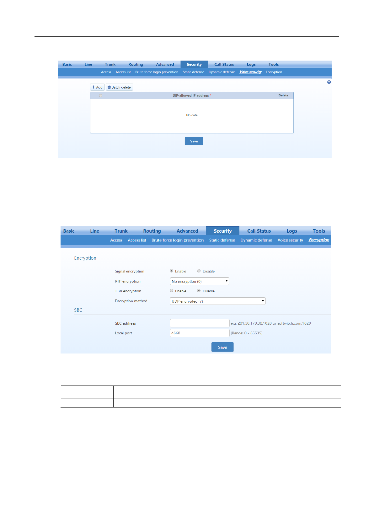
MX Series Voice Gateway User Manual
Name
Description
Signal encryption
Choose whether to encrypt signaling. By default, this is not selected.
Figure 2-63 Voice Security Configuration Interface
2.7.8 Encryption
After login, click Security>Encryption to open this interface.
Figure 2-64 Encryption Configuration Interface
Table 2-41 Encryption Configuration Parameters
New Rock Technologies, Inc. 99
Page 100

User Manual MX Series Voice Gateway
Name
Description
Encryption method
Set the gateway encryption method, default is 7. The optional parameters as below:
2:TCP not encrypted
3: TCP encrypted
6: UDP not encrypted
7: UDP encrypted
8: Using keyword
10: RC4
13: Encrypt13
14: Encrypt14
16: Word reverse(263)
17: Word exchange(263)
18: Byte reverse(263)
19: Byte exchange(263)
20:VOS
Encryption key
You may obtain this from service provider
RTP encryption
Choose whether to encrypt RTP voice pack, the default is 0.
0: no encryption
1: entire message
2: header only
3: the data body only
T.38 encrypt
Select to encrypt T.38 fax media stream packets. By default, this is not selected.
Session Border
Proxy
Encryption method numbered 2, 3, 6 and 7 are used only when the device is connected to a New
Rock SBC.
SBC address
Set the IP address and port number of session border proxy server. The character “:” must be
used between IP address and port number.
Server address could be set into IP address or domain name. When a domain name is used, it is
required to configure DNS server on the "Basic > Network" page. Example: 201.30.170.38:1020
or sbc.com:1020.
Local port
Signaling port assignment of the gateway, the default value is 4660. Signaling port number may
be set at will, but cannot conflict with other ports of equipment.
2.7.9 VPN (Available on the HX4E/MX8A)
100 New Rock Technologies, Inc.
A VPN is a virtual private network constructed on the public network. VPN technology is based on the
idea of tunneling. It performs user authentication and data encryption to prevent data transferred over the
public network from being invalidly browsed or changed. Because the VPN is a logical network
constructed on the public network, it is unnecessary to deploy end-to-end physical links, only the VPN
server and VPN client need to be deployed instead, which greatly reduces the network expense.
With a built-in VPN client, the HX4E/MX8Ais ready to be directly connected to the VPN server to avoid
the firewall issues and NAT issues.
When an untrusted network needs to be traversed between the HX4E/MX8A and the SIP server, you are
 Loading...