

Page 1

New Rock Technologies, Inc.
MX100E SIP-ISDN Gateway Series
User Manual
MX100E-1E1/T1
MX100E-2E1/T1
MX100E-4E1/T1
http://www.newrocktech.com
Tel: +86 21-61202700
Fax: +86 21-61202704
Document No.: MB5-E001-P
Document Version: 201404
Page 2

Amendent Records
Document Rev. 01 (Apr, 2014 )
Copyright © New Rock Technologies, Inc. 2014. All rights reserved.
All or part of this document may not be excerpted, reproduced and transmitted in any form or by any
means without prior written permission from the company.
Page 3

Contents
1 Overview ..................................................................................................................................................... 1-1
1.1 Product Introduction ........................................................................................................................................... 1-1
1.2 Features ............................................................................................................................................................. 1-1
1.3 Equipment Structure .......................................................................................................................................... 1-2
1.3.1 Front & Back Panel ................................................................................................................................. 1-2
1.3.2 CON Port ................................................................................................................................................ 1-4
1.3.3 Specifications ......................................................................................................................................... 1-5
2 Installation Preparation ............................................................................................................................. 2-1
2.1 Installation Precautions ...................................................................................................................................... 2-1
2.2 Site Requirements ............................................................................................................................................. 2-1
2.2.1 Temperature and Humidity ..................................................................................................................... 2-1
2.2.2 Cleanliness ............................................................................................................................................. 2-1
2.2.3 Power Supplier ....................................................................................................................................... 2-2
2.2.4 Grounding ............................................................................................................................................... 2-2
2.2.5 Electromagnetic Environment ................................................................................................................. 2-2
2.2.6 Other Facilities ........................................................................................................................................ 2-2
2.3 Opening Inspection ............................................................................................................................................ 2-3
3 Installation .................................................................................................................................................. 3-1
3.1 Tools and Meters ............................................................................................................................................... 3-1
3.2 Rack Mounting ................................................................................................................................................... 3-1
3.2.1 Attaching the Brackets ............................................................................................................................ 3-1
3.2.2 Mounting the Gateway ............................................................................................................................ 3-1
3.3 Installing Cables................................................................................................................................................. 3-2
3.3.1 Connecting Console Port ........................................................................................................................ 3-2
3.3.2 Connecting the Ethernet Cable ............................................................................................................... 3-3
3.3.3 Connecting the T1/E1 Cable ................................................................................................................... 3-3
3.3.4 Connecting the Grounding Cable ........................................................................................................... 3-4
3.3.5 Connecting the Power Cord .................................................................................................................... 3-4
3.3.6 Verifying Installation ............................................................................................................................... 3-5
4 Powering up the Gateway ......................................................................................................................... 4-1
4.1 Verification before Power-up .............................................................................................................................. 4-1
4.1.1 Checking Appearance ............................................................................................................................ 4-1
4.1.2 Checking Power Supply.......................................................................................................................... 4-1
4.1.3 Powering up the Gateway ....................................................................................................................... 4-1
5 Parameter Setting ...................................................................................................................................... 5-1
5.1 Login .................................................................................................................................................................. 5-1
5.2 Buttons Used on Gateway Management Interface ............................................................................................ 5-2
5.3 Basic Configuration ............................................................................................................................................ 5-2
Page 4

5.3.1 Network Configuration ............................................................................................................................ 5-2
5.3.2 System Configuration ............................................................................................................................. 5-4
5.3.3 SIP Configuration ................................................................................................................................... 5-5
5.3.4 TDM Configuration ................................................................................................................................. 5-6
5.3.5 FoIP ........................................................................................................................................................ 5-8
5.3.6 ISDN ....................................................................................................................................................... 5-9
5.4 Advanced Configuration ................................................................................................................................... 5-12
5.4.1 Routing Table ....................................................................................................................................... 5-12
5.4.2 Application Examples of Routing Table ................................................................................................ 5-16
5.4.3 IP Table ................................................................................................................................................ 5-17
5.4.4 Digit Map .............................................................................................................................................. 5-18
5.4.5 System .................................................................................................................................................. 5-20
5.4.6 Security ................................................................................................................................................. 5-21
5.4.7 White List .............................................................................................................................................. 5-22
5.4.8 Media Stream ....................................................................................................................................... 5-22
5.4.9 SIP Related Configuration .................................................................................................................... 5-23
5.4.10 RADIUS .............................................................................................................................................. 5-25
5.4.11 Encryption ........................................................................................................................................... 5-26
5.4.12 Tones.................................................................................................................................................. 5-27
5.5 Status ............................................................................................................................................................... 5-28
5.6 Log Management ............................................................................................................................................. 5-28
5.6.1 System Status ...................................................................................................................................... 5-28
5.6.2 Call Message ........................................................................................................................................ 5-29
5.6.3 ISDN Status .......................................................................................................................................... 5-30
5.6.4 System Startup ..................................................................................................................................... 5-31
5.6.5 Manage Log .......................................................................................................................................... 5-32
5.7 System Tool ..................................................................................................................................................... 5-33
5.7.1 Change Password ................................................................................................................................ 5-33
5.7.2 Configuration Export ............................................................................................................................. 5-33
5.7.3 Configuration Import ............................................................................................................................. 5-34
5.7.4 Software Upgrade ................................................................................................................................. 5-34
5.7.5 Restore Factory Settings ...................................................................................................................... 5-36
5.7.6 Software Restart ................................................................................................................................... 5-37
5.7.7 System Reboot ..................................................................................................................................... 5-37
5.8 Version Information .......................................................................................................................................... 5-37
5.9 Logout .............................................................................................................................................................. 5-37
Page 5

Contents of Figure
Figure 1-1 Front Panel ............................................................................................................................................. 1-2
Figure 1-2 Back Panel ............................................................................................................................................. 1-4
Figure 3-1 Installation of MX100E Series L-shape Brackets .................................................................................... 3-1
Figure 3-2 Mount MX100E to Rack .......................................................................................................................... 3-2
Figure 3-3 Cable of Connecting MX100E CON ....................................................................................................... 3-3
Figure 3-4 Connecting the T1/E1 Cable ................................................................................................................... 3-4
Figure 5-1 Login Interface for MX100E Gateway Configuration ............................................................................... 5-1
Figure 5-2 Network Configuration Interface ............................................................................................................. 5-2
Figure 5-3 System Configuration Interface .............................................................................................................. 5-5
Figure 5-4 SIP Configuration Interace...................................................................................................................... 5-6
Figure 5-5 TDM Configuration Interface ................................................................................................................... 5-7
Figure 5-6 FoIP Configuration Interface ................................................................................................................... 5-9
Figure 5-7 ISDN Configuration Interface 1 ............................................................................................................. 5-10
Figure 5-8 ISDN Configuration Interface 2 ............................................................................................................. 5-10
Figure 5-9 ISDN configuration Interface 3 .............................................................................................................. 5-12
Figure 5-10 Configuration Interface for Routing Table ........................................................................................... 5-13
Figure 5-11 Configuration Interface for IP Table .................................................................................................... 5-17
Figure 5-12 Configuration Interface for Digit Map .................................................................................................. 5-18
Figure 5-13 System Advanced Configuraiton Interface .......................................................................................... 5-20
Figure 5-14 Security Configuration Interface ......................................................................................................... 5-21
Figure 5-15 White List Configuration Interface ....................................................................................................... 5-22
Figure 5-16 Media Stream Configuration Interface ................................................................................................ 5-22
Figure 5-17 SIP Related Configuration Interface ................................................................................................... 5-24
Figure 5-18 RADIUS Configuration Interface ......................................................................................................... 5-25
Figure 5-19 Encryption Configuration Interface ..................................................................................................... 5-26
Figure 5-20 Tones Configuration Interface ............................................................................................................ 5-27
Figure 5-21 ISDN Status Interface ......................................................................................................................... 5-28
Figure 5-22 System Status Interface...................................................................................................................... 5-29
Figure 5-23 Call Message Interface ....................................................................................................................... 5-30
Figure 5-24 ISDN Status Interface ......................................................................................................................... 5-30
Figure 5-25 System Startup Interface .................................................................................................................... 5-32
Figure 5-26 Manage Log Interface ......................................................................................................................... 5-32
Figure 5-27 Change Password Interface ............................................................................................................... 5-33
Figure 5-28 Configuration Export Interface ............................................................................................................ 5-34
Figure 5-29 Configuration Import Interface ............................................................................................................ 5-34
Figure 5-30 Interface of Upgrade ........................................................................................................................... 5-35
Figure 5-31 File Upload Interface .......................................................................................................................... 5-35
Figure 5-32 Upgrade Interface ............................................................................................................................... 5-36
Figure 5-33 Prompt of Upgrade Process ............................................................................................................... 5-36
Figure 5-34 Interface of Successful Upgrade ......................................................................................................... 5-36
Figure 5-35 Version Information Interface .............................................................................................................. 5-37
Page 6

Contents of Table
Table 1-1 Front Panel .............................................................................................................................................. 1-2
Table 1-2 Indicators ................................................................................................................................................. 1-3
Table 1-3 Pinouts of Ethernet Ports ......................................................................................................................... 1-3
Table 1-4 Pinouts of T1/E1 Module ......................................................................................................................... 1-4
Table 1-5 Description of Back Panel ........................................................................................................................ 1-4
Table 1-6 Standard Table for Lead Wire of Pin at Configuration Port (CON) ........................................................... 1-4
Table 1-7 Attributes of CON Port ............................................................................................................................. 1-4
Table 1-8 Specifications ........................................................................................................................................... 1-5
Table 2-1 Standard Configuration ............................................................................................................................ 2-3
Table 5-1 Network Configuration Interface .............................................................................................................. 5-2
Table 5-2 System Configuration Parameters ........................................................................................................... 5-5
Table 5-3 Codec Methods Supported by Gateway .................................................................................................. 5-5
Table 5-4 SIP Configuration Parameters ................................................................................................................. 5-6
Table 5-5 TDM Configuration Parameters ............................................................................................................... 5-7
Table 5-6 Operated Numbers and Translation Rules .............................................................................................. 5-7
Table 5-7 FoIP Configuration Parameters ............................................................................................................... 5-9
Table 5-8 ISDN Configuration Parameters ............................................................................................................ 5-11
Table 5-9 Routing Table Format ............................................................................................................................ 5-14
Table 5-10 Number Transformations ..................................................................................................................... 5-15
Table 5-11 Routing Destination ............................................................................................................................. 5-16
Table 5-12 Description of Digit map ....................................................................................................................... 5-18
Table 5-13 Advanced System Configuration Parameters ...................................................................................... 5-20
Table 5-14 Security Configuration Parameters ...................................................................................................... 5-21
Table 5-15 Media Stream Configuration Parameters ............................................................................................. 5-23
Table 5-16 SIP Related Configuration Parameter .................................................................................................. 5-24
Table 5-17 RADIUS Configuration Parameter ....................................................................................................... 5-25
Table 5-18 Encryption Configuration Interface ....................................................................................................... 5-26
Table 5-19 Tones Configuration Parameters ......................................................................................................... 5-27
Table 5-20 Status Parameters ............................................................................................................................... 5-28
Table 5-21 System Status Parameters .................................................................................................................. 5-29
Table 5-22 ISDN Status Parameters...................................................................................................................... 5-30
Table 5-23 Manage Log Parameters ..................................................................................................................... 5-32
Page 7

MX100E SIP-ISDN Gateway Series User Manual
www.newrocktech.com 1-1
1 Overview
1.1 Product Introduction
The MX100E gateway (hereinafter referred to as the MX100E) is one of VoIP product series developed
by
New Rock Technologies Inc. It uses the SIP and T1/E1 interfaces for the inter-conversion of IP packets
and PCM signals, allowing the interworking of the IP-based new-generation voice network to legacy
Public Switched Telephone Network (PSTN), and the private branch exchange (PBX) of an enterprise.
As a carrier-class VoIP gateway, the MX100E is designed under the requirements of telecom operators,
integrators, value-added service providers as well as large and medium-sized enterprises for VoIP
services. The MX100E has distinctive advantages over other similar products in terms of performance,
system reliability, compatibility and cost performance. In addition, the MX100E has efficient
software/hardware architecture and powerful DSP processing capabilities, ensuring the realization of
major functions (including the conversion between PCM signals and IP packets, G.711 or G.729A
encoding and decoding of voice signal, and echo cancellation, etc.) even under full load conditions.
By supporting the ISDN PRI signalling, the MX100E can control its calls with the PSTN or PBX. The
call control between the MX100E and media gateway controller (softswitch) is carried out through
Session Initiation Protocol (SIP). By now, the MX100E has successfully passed the interoperability test
with various softswitch platforms and IP PBX products in domestic and overseas markets.
1.2 Features
The MX100E has the following characteristics:
High performance
The DSP chip with powerful voice processing used by the MX100E is developed by the TI Company. Its
DSP daughter card ensures a 6000 MIPS processing capability for each gateway, enabling the MX100E
to provide functions of voice signal processing (G.711, G.729A, and G.723.1), echo cancellation, and fax
relay (T.38) under full load conditions (120 calls).
High security
The network security of the MX100E has been confirmed by NSFOCUS, a proven global leader in
providing enterprise-level network security solutions and services. To ensure a better security, the
MX100E supports Secure Shell (SSH) and Hypertext Transfer Protocol over Secure Socket Layer
(HTTPS), and provides functions including signalling and media stream encryption, automatic password
strength test, password change notification, password anti-crack, ciphertext data storage, external network
access control, blacklist/whitelist, and system log backup.
High reliability and maintainability
Page 8
User Manual MX100E SIP-ISDN Gateway Series
1-2 www.newrocktech.com
To meet the requirements of telecom operators on the gateway reliability, the hardware design of the
MX100E, from architecture to component selection, takes full consideration of improving the mean time
between failures (MTBF), including features such as redundant power supply option and dual Ethernet
ports. In addition, the MX100E uses a web-based graphical management interface to facilitate user
configuration and routine maintenance.
Low cost and high reward
How to reduce cost and investment risk is one of the major challenges a user faces when choosing an
IP-based new generation of voice device. The MX100E helps reducing users’ cost by increasing new
functions and applications to follow the ongoing evolution of VoIP technologies. This feature can be
realized through New Rock’s software upgrade free of charge policy within the life cycle of the MX100E.
In support of multiple protocols
The MX100E supports different kinds of protocols including Session Initiation Protocol (SIP), Real-time
Transport Protocol (RTP), Trivial File Transfer Protocol (TFTP), File Transfer Protocol (FTP), Hypertext
Transfer Protocol (HTTP), Session Traversal Utilities for NAT (STUN), and Simple Network
Management Protocol (SNMP). Also, the MX100E supports different technologies including ISDN PRI
signalling, G.711, G.729A, or G.723.1 encoding and decoding, G.168 echo cancellation, Dual-Tone
Multi-frequency (DTMF) message transmission (RFC 2833), and fax relay (T.38).
High interoperability
By now, the MX100E has successfully passed the interoperability test with various softswitch platforms
and IP PBX products in domestic and overseas markets.
1.3 Equipment Structure
1.3.1 Front & Back Panel
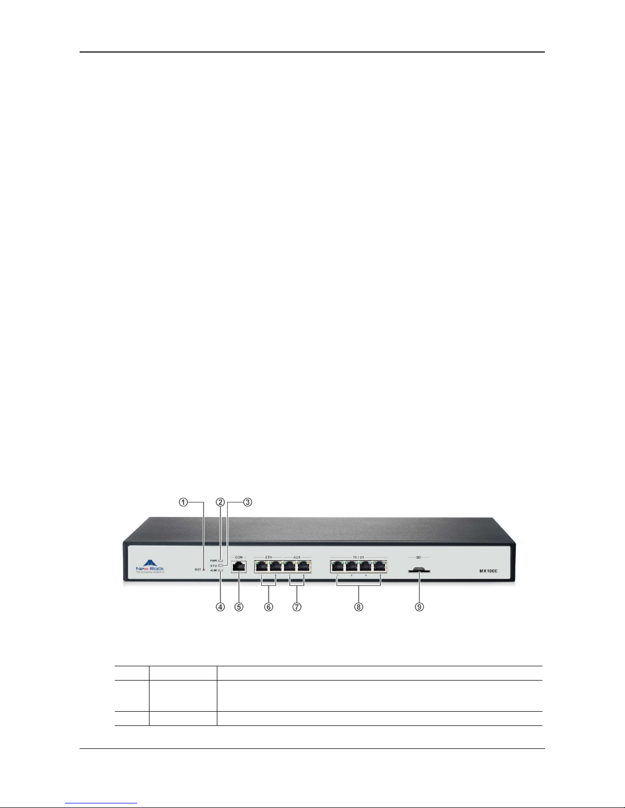
Figure 1-1 Front Panel
Table 1-1 Front Panel
# Mark Description
① RST
Pressing the RST button for less than three seconds: no action will be taken.
Pressing the RST button for more than three seconds: the factory settings will be restored.
② PWR Indicators for power supply, system status and alarm, respectively.
Page 9

MX100E SIP-ISDN Gateway Series User Manual
New Rock Technologies, Inc. 1-3
# Mark Description
③ STU
④ ALM
⑤ CON A configuration interface.
⑥ ETH
Specifies an RJ45 module interface.
Interfaces ETH1 and ETH2 share the same IP address for allowing access to the external
network. Dual-LAN redundancy is supported.
⑦ AUX
An RJ45 interface.
Interfaces AUX1 and AUX2 share the same IP address for local management and
configuration.
⑧ T1/E1
An RJ45 interface, in support of 1 T1/E1, 2 T1/E1, and 4 T1/E1. Each T1 interface
supports the maximum 24 voice channels; each E1 interface supports the maximum 30
voice channels with ISDN PRI signalling.
⑨ SD A SD card socket.
Table 1-2 Indicators
Mark Function Status Description
PWR
Power
Indication
Green Power on
Off Power off
STU
Status
Indication
Off System locked and inactive
Green Flash Normal operation
Red
System in the process of power up and not in the normal operation
mode
Red Flash System in a diagnostic mode and able to execute limited operation
ALM
Alarm
Indication
Green No alarms
Red Flash New alarms occurred but not confirmed
Red Alarms existed and all alarm information confirmed
ETH
Interface state
indicator
Long green The link has been established but no service traffic is transmitted.
Blinking green Service traffic is being transmitted on the link.
Off The link is not established.
AUX
Interface state
indicator
Long green The link has been established but no service traffic is transmitted.
Blinking green Service traffic is being transmitted on the link.
Off The link is not established.
T1/E1
Interface state
indicator
Long green The connection works normally.
Blinking red A remote alarm is generated.
Long red A local alarm is generated.
Off No connection is established.
Table 1-3 Pinouts of Ethernet Ports
RJ45 Pin-out 1 2 3 6
Description TX+ TX- RX+ RX-
Page 10
User Manual MX100E SIP-ISDN Gateway Series
1-4 www.newrocktech.com
Table 1-4 Pinouts of T1/E1 Module
RJ45 Pin-out 1 2 3 4 5 6 7 8
Description RXRing RXTip NC TXRing TXTip NC NC NC
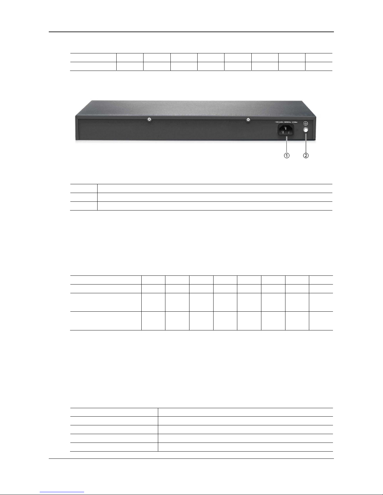
Figure 1-2 Back Panel
Table 1-5 Description of Back Panel
#
Description
① AC power socket, 100-240 VAC voltage input.
② Ground pole.
1.3.2 CON Port
The MX100E provides one configuration interface (CON) of RJ45 interface for local management and
debugging.
Table 1-6 Standard Table for Lead Wire of Pin at Configuration Port (CON)
Pin number of RJ45 plug 1 2 3 4 5 6 7 8
Description NC NC TXD GND GND RXD NC NC
Pairing connection with DB9
female plug
2 5 3
Pairing connection with DB25
male plug
3 7 2
The configured interface is connected to the RS232 port on the PC, allowing the PC to establish the
connection with the MX100E by configuring a terminal emulator. The configured interface of MX100E is
in a 3-wire configuration: one TXD (data transmission terminal), one RXD (data reception terminal), and
one GND (ground terminal).
A female adapter of RJ45 to DB9 can be prepared by yourself.
Table 1-7 Attributes of CON Port
Attributes Description
Connector RJ45
Interface count 1
Interface standard RS232
Baud rate 115200
Page 11

MX100E SIP-ISDN Gateway Series User Manual
New Rock Technologies, Inc. 1-5
Attributes Description
Data bit 8
Parity No
Stop bit 1
Traffic control No
1.3.3 Specifications
Table 1-8 Specifications
Item Description
Basic
Ethernet RJ45, 4×10/100M Base-T, self-adaptive
E1/T1Interface 4, 120 simultaneous VoIP calls
SD Interface 1
CON Interface RJ45
System Memory 256 MB
System Flash 32 MB
Processor
TI AM3352
DSP
TI C5509
Power ~100-240V, 50/60Hz, 1A
Power Consumption
60 W (Max)
Size (H×W×D) 44×440×300 mm, 1U formfactor
Weight net weight: 3 kg gross weight(with box): 5 kg
Environment Requirements
Operating Environment
0 to 40℃, Non-Condensing Humidity 10% to 95%
Storage Environment
-10 to 60℃, Non-Condensing Humidity 10% to 95%
Page 12

MX100E SIP-ISDN Gateway Series User Manual
www.newrocktech.com 2-1
2 Installation Preparation
For avoidance of personal injury and device damage, please read this cha pter carefully before installation.
2.1 Installation Precautions
For your safety, please follow the precautions when MX100E is installed and used.
Keep the site far from the heat and humidity
Take precautions with use of high-voltage electricity
Please let the experienced or trained operator to install and maintain MX100E
Wear static discharge wrist strap
Ensure the proper electric ground of installed equipment
Properly connect the power cable to MX100E
Do not plug the power cable when in use
UPS is advised
2.2 Site Requirements
2.2.1 Temperature and Humidity
Check the temperature and humidity of equipment room. To ensure the normal operation and long service
life of the gateway, the temperature and humidity in the room should be kept at the proper range.
The humidity in the equipment room should be kept between 10% and 90% (non-condensing). Abnormal
humidity condition may cause problems to the gateway:
Long term high humidity may lead to bad insulation and even cause electricity leakage, mechanical
property change and corrosion.
Low humidity is likely to leave captive screws to loose due to static electricity built up and the
insulation washer shrunk.
The temperature in the equipment room should be kept between 0℃ and 40℃. Abnormal temperature
condition may cause problems to the gateway:
High temperature acceralets aging of electrical parts and insulation materials.
Low temperature, however, may destabilize the operation of gateway.
2.2.2 Cleanliness
Dust is very harmful to the safe operation of the gateway. Dust that is adsorbed by static electricity acts as
insulator, which not only affects the service life of the gateway but also leads to communication failure.
Therefore, the room for the gateway must be kept clean.
Page 13

User Manual MX100E SIP-ISDN Gateway Series
2-2 www.newrocktech.com
To ensure adequate ventilation to keep the gateway from overheating, there should be adequate clearance
for the air intake and the air exhaust vents. Keep at least 6 cm clearance at the left and right side of the
chassis where the air intake is and at least 15 cm clearance at the rear of the chassis where the exhaust
vents located.
The rack for MX100E should have a good ventilation system.
2.2.3 Power Supplier
Check the power supply system against the electrical specification of the gateway.
2.2.4 Grounding
To maintain good voice quality, proper grounding of the AC supply is critical to minimize the noise from
the AC interference. Therefore, the following conditions must be ensured:
The AC power outlet has a protection ground contact.
The ground contact of AC supplier must be grounded properly.
Avoid sharing the multi-outlet power strip with other devices that may generate electrical interference.
MX100E is chassis based with ground tab.
In a site that can provide ground for the chassis, the ground tab at the rear panel of chassis for MX100E
must be properly grounded.
2.2.5 Electromagnetic Environment
Any possible interference source, wherever it is from, impacts the gateway negatively. To resist the
interference, make sure that:
Keeping the gateway far from radio transimitting station, radar station, and high-frequency devices.
Use electromagnetic shielding when necessary.
The gateway is capable for secondary lighten protection on wires and cables that connected to outside
buildings.The site must provide the primary lighten protection.
The power supply system should be used independently as much as possible and effective measures of
preventing electric grid from interference should be adopted.
Ensure a good power grounding effect of equipment or add a lightning protector.
2.2.6 Other Facilities
Rack/Workbench
MX100E is designed to be installed in a standard 19-inch rack, which should provide adequate
air-flow to cool down the gateway, and should be firm enough to support the weight of the gateway. It
is also recommended the rack is earth grounded properly.
PSTN Line
If the gateway is equipped with T1/E1 interface, be sure to subscribe PSTN lines from local telephone
company and activate the lines prior to the installation.
IP Network
The gateway is connected to IP network through its 10/100 base-T Ethernet port and communicate
with other equipments through the network. Inspect IP network on the site, including router, switch,
cable wiring and etc, and make sure they are ready for the gateway.
AC Power Outlets
Page 14

MX100E SIP-ISDN Gateway Series User Manual
New Rock Technologies, Inc. 2-3
The gateway needs AC power supply, and sometimes the power is provided through a power strip
with extension cord. Verify that each socket outlet on the power strip is equipped with protective earth
contact and the protective action is not negated by using extension power cord.
2.3 Opening Inspection
After the completion of installation preparation, you should open the box for inspection. Make sure the
gateway and all in-box accessories match the description below.
An MX100E with basic configuration should include components as shown in fowling table.
Table 2-1 Standard Configuration
Description Quantity Unit
MX100E 1 Set
Power Cord 1 Set
Grounding Cable 1 Set
Rack Mounting Kits 1 Set
T1/E1 Cable
1~4
Set
The package list is only for reference. Changes may be made without notification. The detailed
inclusions are on the shipping list enclosed in the device package. Please contact your supplier if you
have any question.
Page 15
MX100E SIP-ISDN Gateway Series User Manual
www.newrocktech.com 3-1
3 Installation
3.1 Tools and Meters
Screwdriver
Antistatic wrist strap
Ethernet and console port cables
Power cable
Terminals (a PC running terminal program can be used)
Universal electric meter
Multimeter
3.2 Rack Mounting
The MX100E series chassis are designed to be mounted on a standard 19-inch rack with 1U height.
3.2.1 Attaching the Brackets
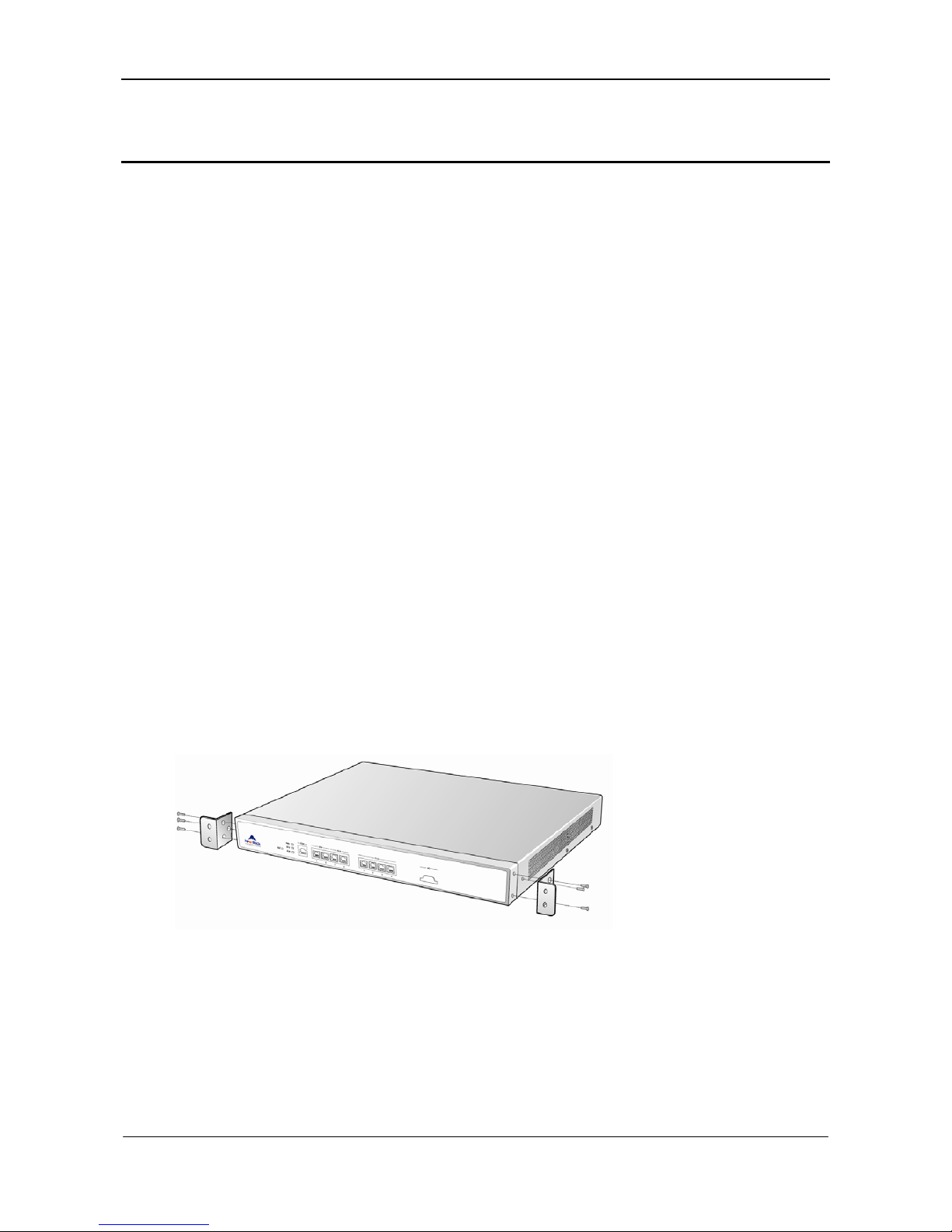
Place the MX100E series chassis on the workbench, take two L-shape rack mounting brackets and screws,
install the brackets at the left and right sides of the equipment, as shown in the fowling figure.
The L-shape brackets are used to secure the gateway to the rack. The brackets cannot support the weight
of the equipment alone. Prior to install the MX100E series chassis into rack, a supporting shelf must be
installed in place where the gateway will sit.
Figure 3-1 Installation of MX100E Series L-shape Brackets
3.2.2 Mounting the Gateway
Attention should be paid during the installation:
Ensure that the rack is firmly attached to the ground and stable.
If the gateway is installed in a closed cabinet shelf, the cabinet must provide adequate air-flow so the
equipments inside can be well ventilated.
If multiple gateways are installed in a rack, it is recommended to keep at lease 1/2U space between
gateways for heat dissipation.
Page 16
User Manual MX100E SIP-ISDN Gateway Series
3-2 www.newrocktech.com
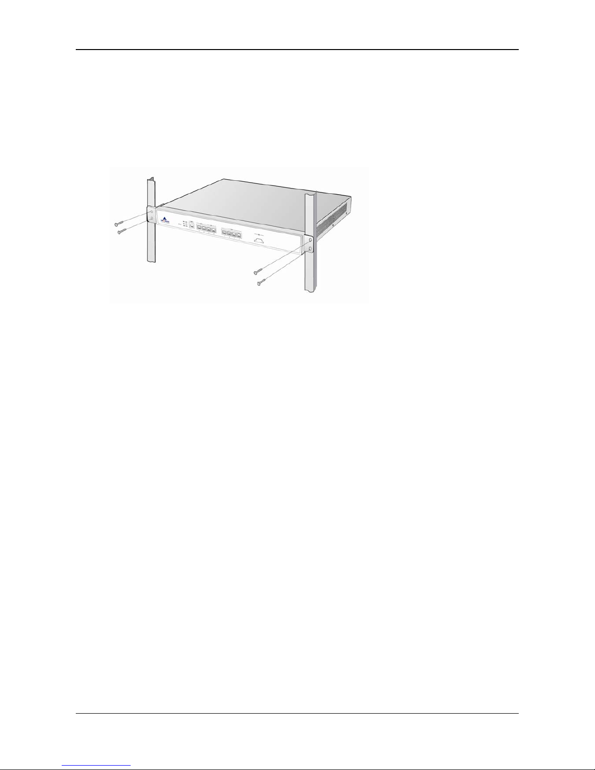
Follow the steps to install the gateway:
Place the gateway on a shelf in the rack.
Slide it to a proper position along the guide rails.
Fix the rack-mount brackets to the rack posts with supplied Phillips screws. Make sure that the
gateway is in level position and securely fixed as shown in fowling figure.
Figure 3-2 Mount MX100E to Rack
The gateway chassis is securely attached to the rack by the rack mounting brackets and the supporting
shelf.
3.3 Installing Cables
3.3.1 Connecting Console Port
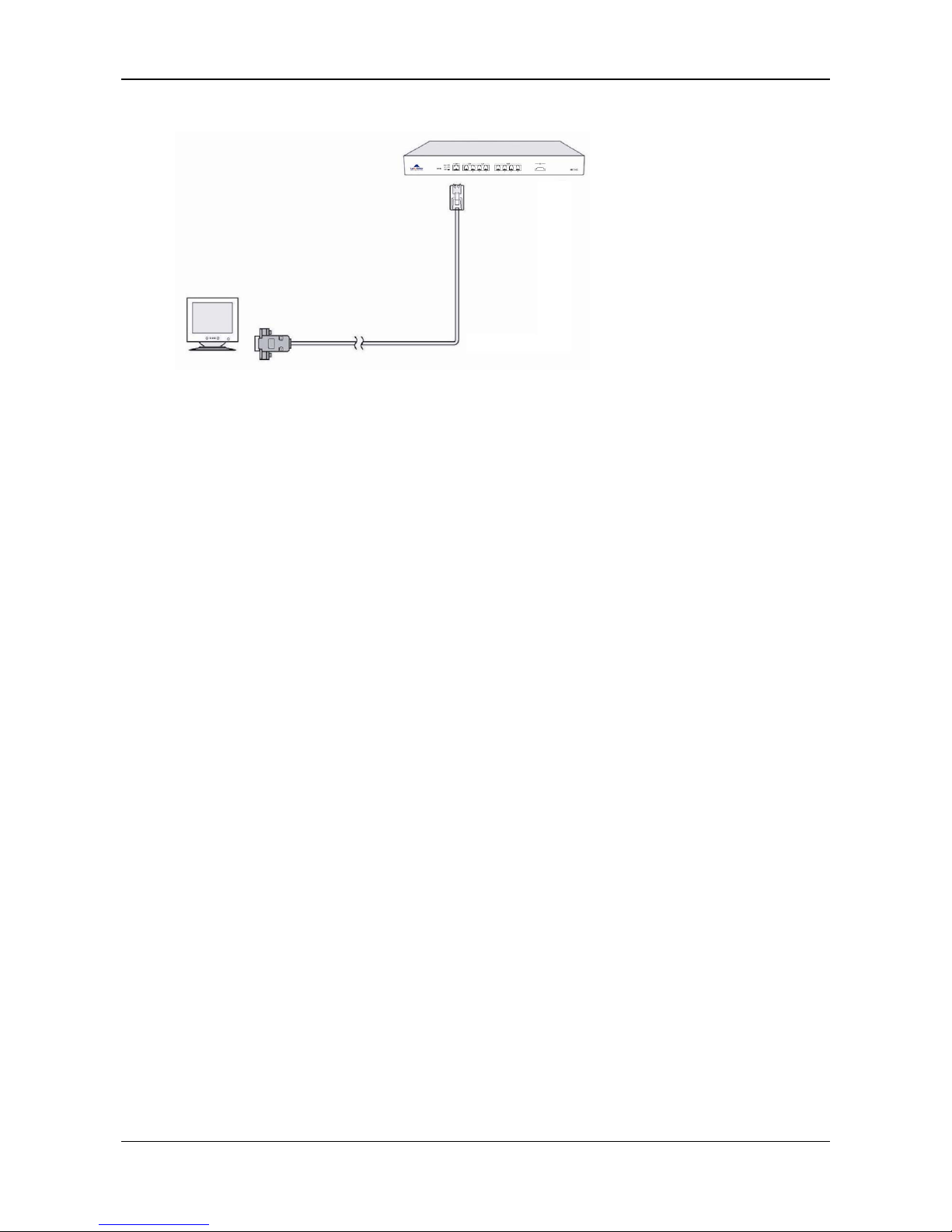
A CON should be provided by MX100E to check errors of the device. Connect the CON with computer’s
RS232 serial ports, then local computers can interwork with the device through simulating terminal
program.
As to MX100E, RJ45 Plug is used. One port is applied for connecting CON, while the other is applied for
DB9 Adapter to insert serial ports of configuration terminal. CON Ratio: 115200.
Console Port cable installation procedure is as followed:
Step1 Choose a terminal (PC).
Step2 Power off the terminal and connect RS232 port with the Console port.
Page 17
MX100E SIP-ISDN Gateway Series User Manual
New Rock Technologies, Inc. 3-3
Figure 3-3 Cable of Connecting MX100E CON
3.3.2 Connecting the Ethernet Cable
The MX100E has the dual-network-interface redundancy function. When one of the network interfaces is
disconnected or does not work well, traffic services can be switched seamlessly to the other one.
The MX100E has two service interfaces, namely ETH1 and ETH2 for your choice. These two interfaces
need to be connected to the same hub, LAN, or WAN. Only one of them works at a time. After Ethernet
cables are inserted, check the indicator state of the interface that is connected first. If the indicator is long
green or blinking green, it indicates that the connection is established properly.
The MX100E has two auxiliary interfaces, namely AUX1 and AUX2. In most cases, no connection is
required for auxiliary interfaces.
3.3.3 Connecting the T1/E1 Cable
MX100E offers RJ45 jack as T1/E1 connector for making ISDN connection with PBX or PSTN.
Please identify the connector type and interface impedance of the other side equipment before making
T1/E1 connection.
If the other side equipment offers same RJ45 jack, use CAT5 cable with RJ45 plugs on both side to make
T1/E1 cable connection. Be sure to mach TX and PX pair according to the PIN specification when
making the CAT5 cable.
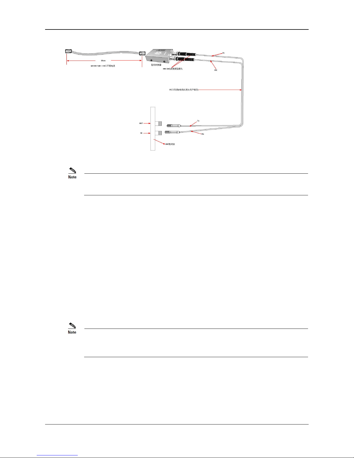
If the other side equipment offers separate TX/RX coax connectors for T1/E1connection, use
RJ45-Balum-Coax cable sets and follow the figure to make the connection.
Page 18
User Manual MX100E SIP-ISDN Gateway Series
3-4 www.newrocktech.com
Figure 3-4 Connecting the T1/E1 Cable
The T1/E1 ports are numbered 1 to 4 from left to right. If the hardware configuration is 1 T1/E1, insert
one end of the T1/E1 cable to the leftmost T1/E1 port on the MX100E.
3.3.4 Connecting the Grounding Cable
When install in equipment room facility providing independent grounding, it is required to connect the
chassis ground tab on MX100E with the protective grounding system in this environment. Proper
grounding not only provides a guarantee for safe operation of the equipment but also enhances the
capacity of the equipment to resist disturbance and ensures the quality of voice communication.
The MX100E series main chassis and expansion chassis are equipped with a M4 grounding screw with a
mark in their backs. Please use the M4 screw to connect the grounding wire.
3.3.5 Connecting the Power Cord
Before connect the power cord, make sure the AC power outlet is provided with a protective earth contact
and the earth contact of the AC power source is proper grounded.
Please contact the gateway supplier if the power LED does not light up after the power is turned on.
Never install and uninstall the gateway or plug and unplug any cable on the gateway when the power
is turned on.
Follow the steps to connect power cord:
Turn the switch of AC power outlet to OFF position.
MX100E use the shipped power cord to connect between the AC input at rear of the chassis and the AC
power outlet.
Page 19

MX100E SIP-ISDN Gateway Series User Manual
New Rock Technologies, Inc. 3-5
3.3.6 Verifying Installation
Installation verification is extremely important, because operations of the gateway depend on its stability,
grounding, and power supply.
Each time you turn on the power during the installation, verify that:
Enough clearance has been reserved around the ventilation openings of the gateway and the
workbench/rack is stable enough.
The protection ground is connected properly.
Proper power is used as specified.
The gateway is correctly connected to console terminal and other devices.
Page 20

MX100E SIP-ISDN Gateway Series User Manual
www.newrocktech.com 4-1
4 Powering up the Gateway
4.1 Verification before Power-up
4.1.1 Checking Appearance
This is a review process of the installation work, including the chassis, wiring, connectors, ports, labels
and site as described in the subsections.
Gateway
Check whether there is adequate clearance around the gateway for thermal, and whether the
workbench or rack for the mounting of the gateway is firm enough.
Check whether the gateway is correctly connected to the configuration terminal and other devices.
Cable
Check whether the Ethernet cable, the T1/E1 cables are connected properly.
Check whether the grounding cable is connected properly.
Check whether the power cord is connected to the proper power supply as required.
Port and Connector
Check whether the ports and connectors are secured.
Equipment Room
Check whether the temperature and humidity in the equipment room are within the proper range. The
humidity should be kept at 10% to 90% non-condensing and the temperature should be kept at 0-40℃.
4.1.2 Checking Power Supply
Check whether the power supply is in normal operation with a multimeter.
4.1.3 Powering up the Gateway
Turn the power switch to ON position. Check the status of PWR LED, and if it is lit the gateway is
powered properly.
Page 21
MX100E SIP-ISDN Gateway Series User Manual
www.newrocktech.com 5-1
5 Parameter Setting
5.1 Login
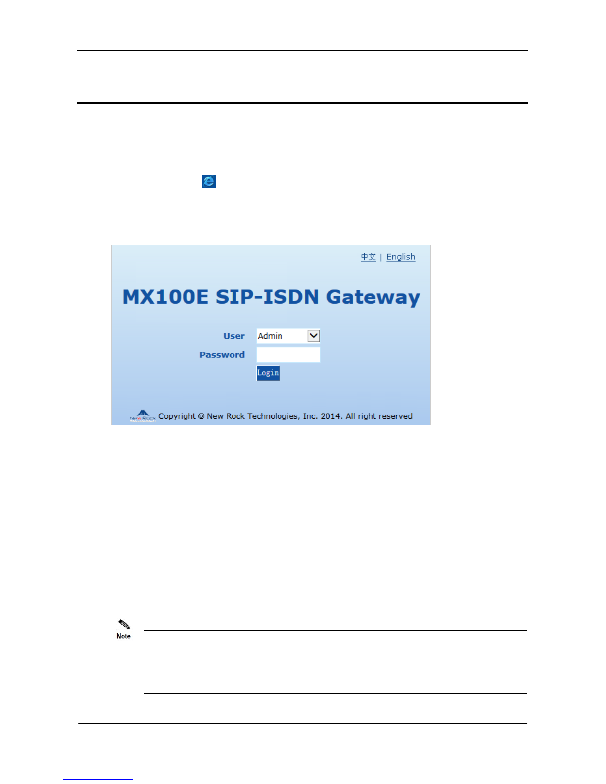
Double-click the icon to open IE browser, and enter the gateway IP address in the browser address
bar (eg. 192.168.2.240), you can enter the login interface for gateway configuration by entering a
password on the login interface.
Figure 5-1 Login Interface for MX100E Gateway Configuration
Both Chinese and English Languages are provided for the Web interface.
Logon users are classified into administrator and operator. The default passwords are mx100
(lowercase letters required) and operator. The password is shown in a cipher for safety.
The administrator can browse and modify all configuration parameters, and modify login passwords.
The operator can browse and modify part of configuration parameters.
The gateways allow multiple users to log in:
The administrator has permission for modification and the operator has permission for browsing;
When multiple users with same level of permission log in, the first has permission for modification,
while the others only have permission for browsing.
The system will confirm timeout if users do not conduct any operation within 10 minutes after login.
They are required to log in again for continuing operations.
Upon completion of configuration, click the Logout button to return to the login page, so as not to
affect the login permission of other users.
Page 22
User Manual MX100E SIP-ISDN Gateway Series
5-2 www.newrocktech.com
5.2 Buttons Used on Gateway Management Interface
Submit buttons are at the bottom of the configuration screens.
Submit Button: Submit configuration information. Users click Submit button after completion of
parameter configuration on a page. A success prompt will appear if configuration information is
accepted by the system; if a “The configuration takes effect after the system is restarted” dialog box
appears, it means that the parameters are valid only after a system restart; it is recommended that users
press the Restart button on the Tool page to enable the configuration after changing all parameters to
be modified.
5.3 Basic Configuration
5.3.1 Network Configuration
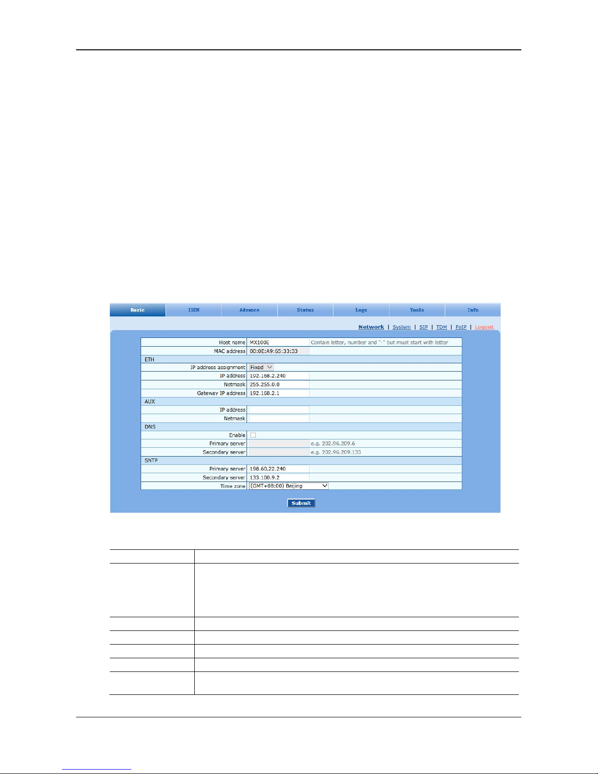
After login, click Basic > Network tab to open the configuration interface.
Figure 5-2 Network Configuration Interface
Table 5-1 Network Configuration Interface
Name Description
Host name
This is the equipment name of a configuration gateway. The default value is MX100E. Users
can set a different name for each gateway to distinguish from each other according to the
deployment plan.
A host name can be a maximum of 48 characters, either letters (A-Z or a-z), numbers (0-9) and
minus sign (-). It may not be null or space and it must start with a letter.
MAC address Display the MAC address of gateway.
ETH
IP address assignment Static IP address is used.
IP address The IP address used by an ETH interface to access the network gateway.
Netmask
The subnet mask is used with an IP address. When the gateways use a static IP address of
ETH, this parameter must be entered.
Page 23

MX100E SIP-ISDN Gateway Series User Manual
www.newrocktech.com 5-3
Name Description
Gateway IP address LAN gateway IP address where the gateways are located.
AUX
IP address
The IP address used by an AUX interface to access the network gateway, which must be in
different network segment with the IP address of the ETH interface.
Netmask
The subnet mask is used with an IP address. When the gateways use a static IP address of
AUX, this parameter must be entered.
DNS
Enable Activate DNS service.
Primary Server
If DNS service is activated, the network IP address of preferred DNS server must be entered,
and there is no default value.
Secondary Server
If DNS service is activated, the network IP address of standby DNS server can be entered here.
It is optional and there is no default value.
SNTP
Primary Server
Enter the IP address of preferred time server here. This parameter must be set due to no default
value.
Secondary Server
Enter the IP address of standby time server here. This parameter must be set due to no default
value.
Page 24

User Manual MX100E SIP-ISDN Gateway Series
5-4 www.newrocktech.com
Name Description
Time Zone Select a time zone, and the parameter values include:
(GMT-11:00) Midway Island
(GMT-10:00) Honolulu. Hawaii
(GMT-09:00) Anchorage, Alaska
(GMT-08:00) Tijuana
(GMT-06:00) Denver
(GMT-06:00) Mexico City
(GMT-05:00) Indianapolis
(GMT-04:00) Glace_Bay
(GMT-04:00) South Georgia
(GMT-03:30) Newfoundland
(GMT-03:00) Buenos Aires
(GMT-02:00) Cape_Verde
(GMT) London
(GMT+01:00) Amsterdam
(GMT+02:00) Cairo
(GMT+03:00) Moscow
(GMT+03:30) Teheran
(GMT+04:00) Muscat
(GMT+04:30) Kabul
(GMT+05:30) Calcutta
(GMT+05:00) Karachi
(GMT+06:00) Almaty
(GMT+07:00) Bangkok
(GMT+08:00) Beijing
(GMT+09:00) Tokyo
(GMT+10:00) Canberra
(GMT+10:00) Adelaide
(GMT+11:00) Magadan
(GMT+12:00) Auckland
5.3.2 System Configuration
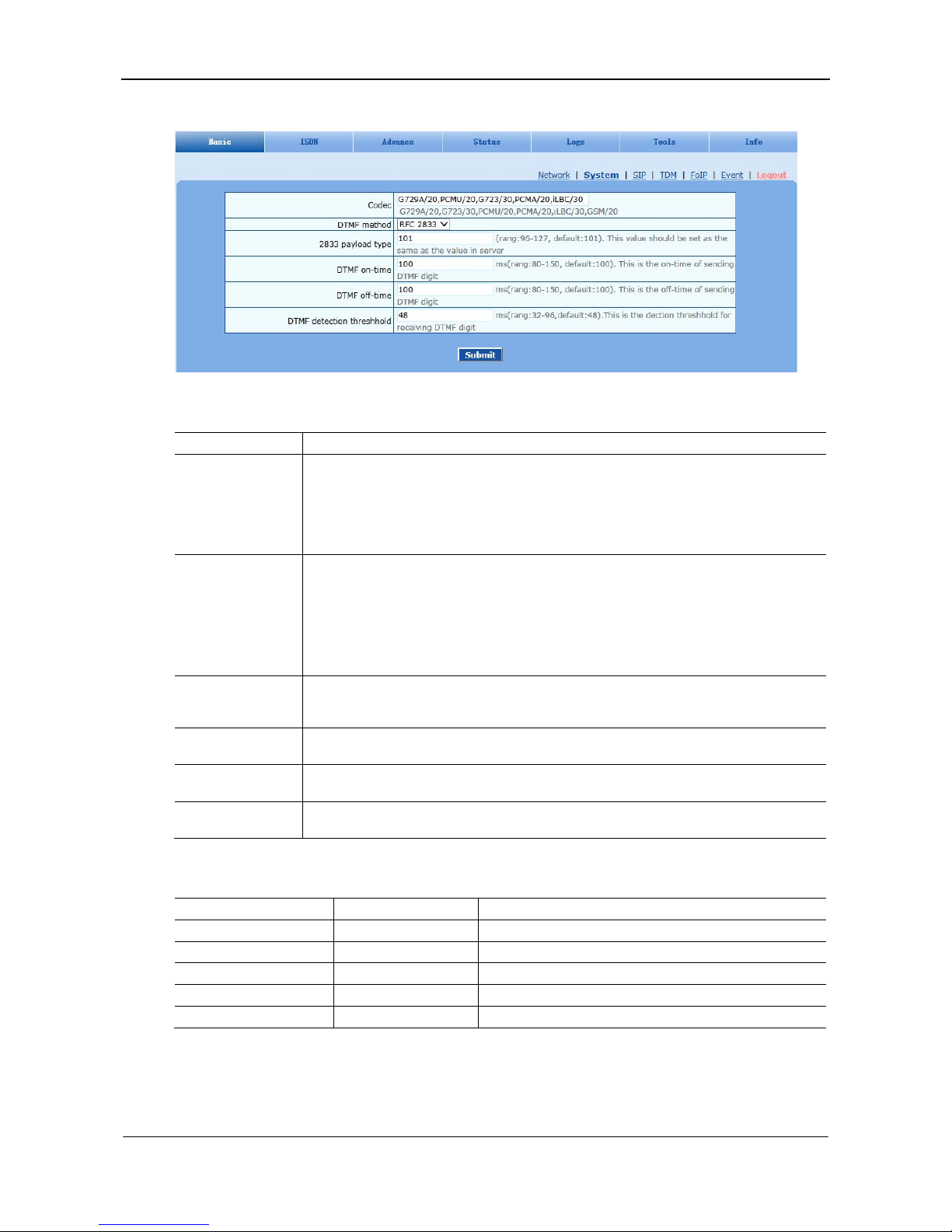
After login, click Basic > System tab to open the system configuration interface.
Page 25
MX100E SIP-ISDN Gateway Series User Manual
www.newrocktech.com 5-5
Figure 5-3 System Configuration Interface
Table 5-2 System Configuration Parameters
Name Description
Codec
Codecs methods supported by the gateways include G729A/20, G723/30, PCMU/20, PCMA/20,
iLBC/30 and GSM/20 (as shown in table 2-5). This parameter must be set due to no default
value.
Several encoding methods can configure in this item at the same time, separated with “,” in the
middle; the gateways will negotiate with the platform in the order from front to back when
configuring the codec methods
DTMF method
Transmission modes of DTMF signal supported by the gateways include Audio, RFC 2833 and
SIP INFO. The default value is Audio.
Audio: DTMF signal is transmitted to the platform with sessions;
SIP INFO: Separate DTMF signal from sessions and transmit it to the platform in the form
of SIP INFO messages;
RFC 2833: Separate DTMF signal from sessions and transmit it to the platform through
RTP data package in the format of RFC2833.
2833 payload type
Used with RFC 2833 in the DTMF transmission modes. The default value of 2833 payload type
is 101. The effective range available: 96-127. This parameter should match the setting of
far-end device (e.g. platform).
DTMF on-time
This parameter sets the on time (in ms) of DTMF signal sent from FXO port. The default value
is 100 ms. Generally, the duration time should be set in the range of 80-150 ms.
DTMF off-time
This parameter sets the off time (ms) of DTMF signal sent from FXO port. The default value is
100 ms. Generally, the interval time should be set in the range of 80-150 ms.
DTMF detection
threshold
Minimum duration time of effective DTMF signal. Its effective range is 32-96 ms and the
default value is 48 ms. The greater the value is set, the more stringent the detection is.
Table 5-3 Codec Methods Supported by Gateway
Codec Supported Bit Rate (Kbit/s) Time Intervals of RTP Package Sending (ms)
iLBC 13.3/15.2 20/30
GSM 13 20
G729A 8 10/20/30/40
G723 5.3/6.3 30/60
PCMU/PCMA 64 10/20/30/40
5.3.3 SIP Configuration
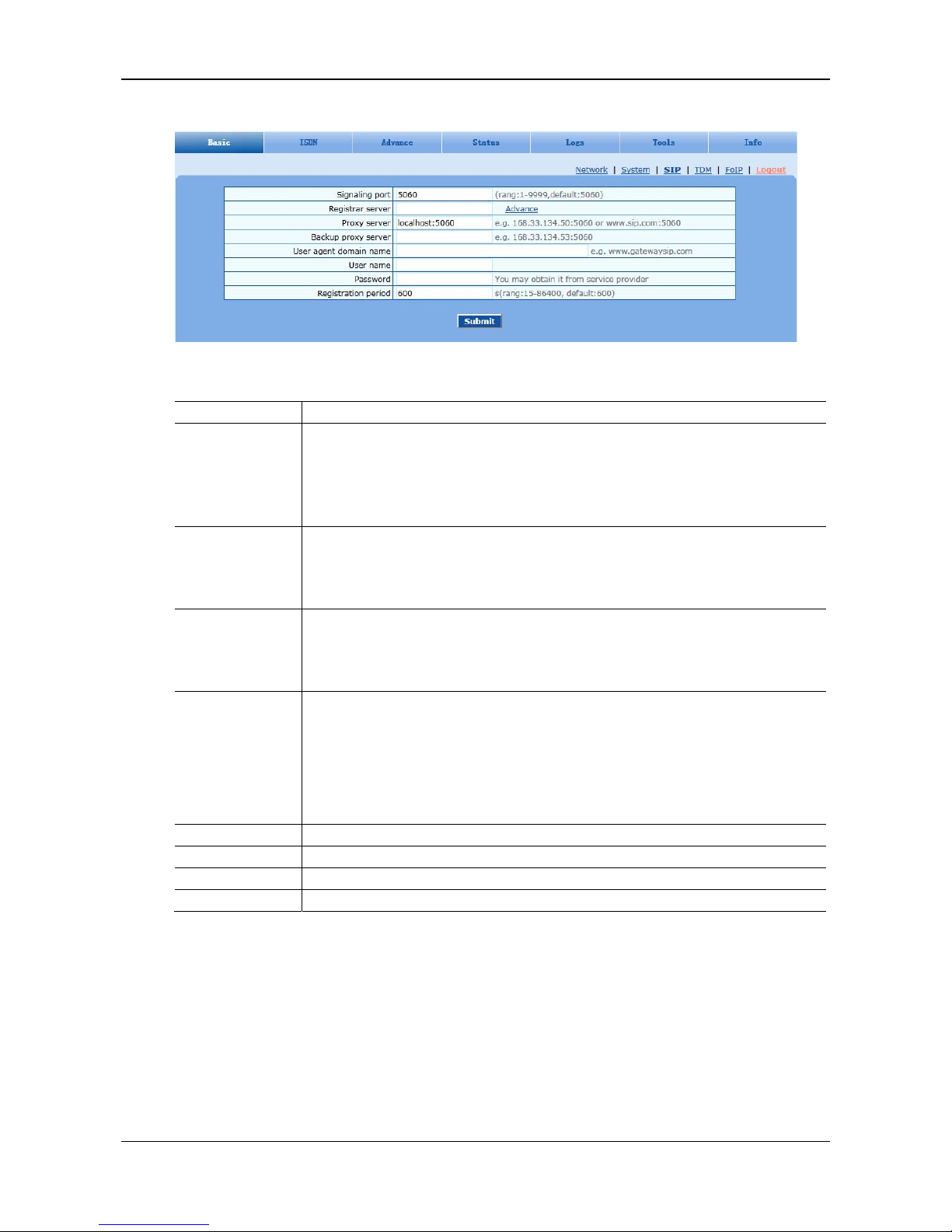
After login, click Basic > SIP tab to open the SIP configuration interface.
Page 26
User Manual MX100E SIP-ISDN Gateway Series
5-6 www.newrocktech.com
Figure 5-4 SIP Configuration Interace
Table 5-4 SIP Configuration Parameters
Name Description
Signaling port
Configure the UDP port for transmitting and receiving SIP messages, with its default value
5060.
If the MX100E is connected directly to the Internet, it’s recommended to change the default
port value to prevent hacker attacks.
Note: The signaling port number can be set in the range of 1-9999, but cannot conflict with the
other port numbers used by the equipment.
Register server
Configure the address and port number of SIP register server, and the address and port number
are separated by “:”. The register server address can be an IP address or a domain name. When a
domain name is used, it is required to activate DNS service and configure DNS server
parameters on the page of configuring network parameters. For example: 201.30.170.38:5060,
register.com:5060.
Proxy server
Configure the IP address and port number of SIP proxy server, and the address and port number
are separated by “:”. The proxy server address can be set to an IP address or a domain name.
When a domain name is used, it is required to activate DNS service and configure DNS server
parameters on the page of configuring network parameters. Examples of complete and effective
configuration: 201.30.170.38:5060, softswitch.com:5060.
Backup proxy server
Configure the IP address and port number of backup proxy server. Add the address of calling
proxy server here, and the gateways can support selection function of multiple softswitch
addresses through IP address. The format must be IP address format and complete and effective
configuration, e.g. 202.202.2.202:2727. The proxy and register severs must be identical.
Conditions for falling over to the backup proxy server (any):
Gateway register is timeout.
No response to master server calls is timeout.
User name Configure the user name as part of the account for registration.
Password Password as part of account information is used for authentication by platform.
Password Password as part of account information is used for authentication by platform.
Registration period Valid time of SIP re-registration in second. Its default value 3600.
5.3.4 TDM Configuration
In case of full configurations, the MX100E has one 4T1/E1 card, with four interfaces numbering TDM1
to TDM4 from left to right. You are recommended to set parameters corresponding to the interface
configured. Parameters for each interface are identical. You can set different parameter values for each
interface as needed. For parameter setting, take the TDM1 as an example:
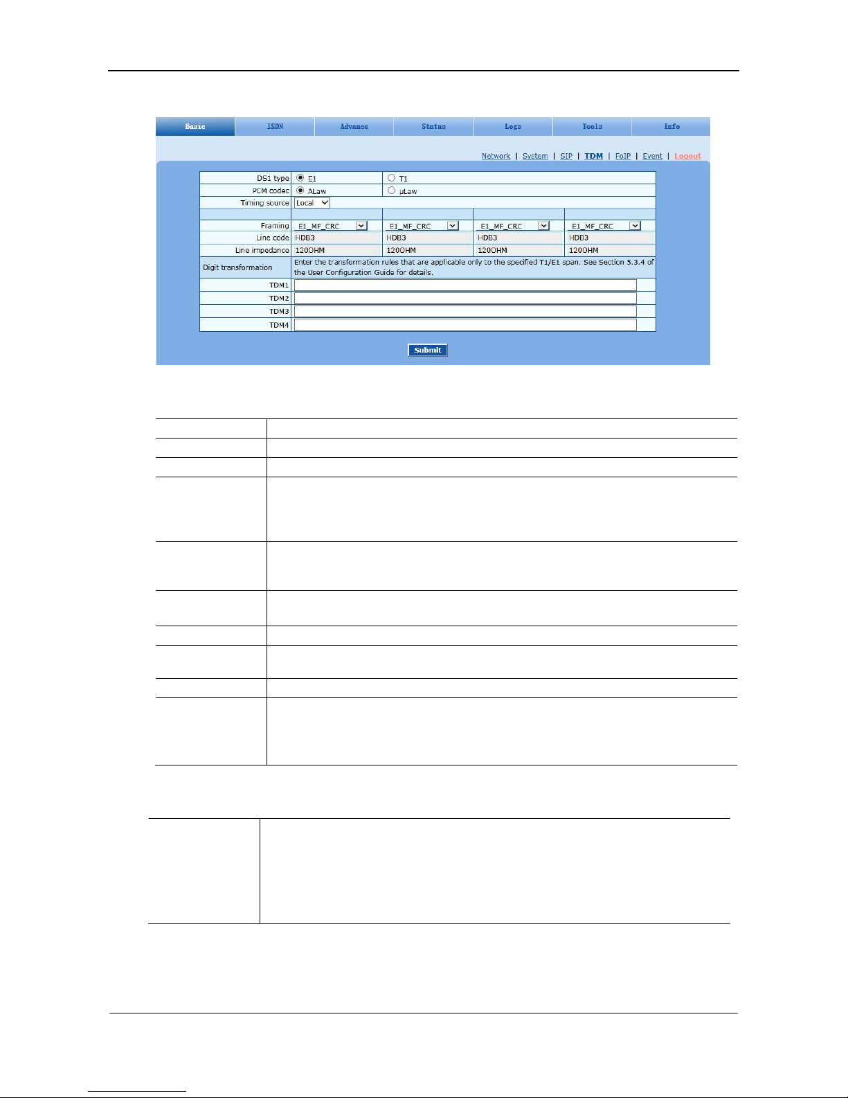
After login, click Basic > TDM tab to open the configuration interface.
Page 27
MX100E SIP-ISDN Gateway Series User Manual
www.newrocktech.com 5-7
Figure 5-5 TDM Configuration Interface
Table 5-5 TDM Configuration Parameters
Name Description
DS1 type DS1 Type configures if the T1/E1 interface operates as a T1 or E1 interface.
PCM codec Allows configuring the PCM encoding type. Allowed settings are ULaw and ALaw.
Timing source Set the clock synchronization source.
If the TDM1 is chosen, it indicates that the MX100E synchronizes its clock with the opposite
device connected to the first TDM interface.
If the Local is chosen, it indicates that the MX100E synchronizes with the local device.
Framing
If the MX100E DS1 Type is set to T1 then Line Framing can be set to D4, SF (Superframe), ESF
(Extended Superframe) mode.
If the MX100E DS1 Type is set to E1 then Line Framing can be set to E1_MF_CRC mode.
Line code If the MX100E DS1 Type is set to T1 then Line Code can be set to B8ZS or AMI.
If the MX100E DS1 Type is set to E1 then Line Code can be set to HDB3.
Line impedance The configuration is displayed when E1 is chosen, with the value of 120 OHM.
Line length
The configuration is displayed when T1 is chosen, with 0 db and 7.5 db for long haul and 36.67
m for short haul.
Digit adjust Its configuration process is complicated. If necessary, please contact the technical support.
Number
Transformation
Number Transformation on each T1/E1 link.
Rule format for number transformation on a single T1/E1 link:
Operated number: Operation rule set/Operated number: Operation rule set
For details about operated numbers and translation rules, see Table 5-6.
Table 5-6 Operated Numbers and Translation Rules
Operated Number
The four following types of operated numbers exist:
InCPN: Operates the calling numbers of calls from ISDN.
InCDPN: Operates the called numbers of calls from ISDN.
OutCPN: Operates the calling numbers of calls to ISDN.
OutCDPN: Operates the called numbers of calls to ISDN.
Page 28

User Manual MX100E SIP-ISDN Gateway Series
5-8 www.newrocktech.com
Operation Rue Set
There are four types of operation rules: matching rules, substitution rules, insertion rules, and
deletion rules.
The operation rule set is a combination of the four types of rules. If the user does not set a
matching rule in the operation rule set, the operation applies to all numbers corresponding to the
operated number.
Different types of rules are separated by a slash. Rules are executed in sequence from left to
right.
Matching Rule
Matching rule CnSmmm or C-nSmmm, where n is an integer greater than or equal to 1, and
mmm is a number string.
CnSmmm: Matches the number string mmm behind S from left t o right, starting from the nth
digit of the number on the left.
C-nSmmm: Matches the number string mmm behind S from right to left, sta rting from the
nth digit of the number on the right.
Replacing Rule
Replacing rule RnSmmm or R-nSmmm, where n is an integer gre ater t han or equal to 1, mmm i s
a number string, and Y is assumed to be the length of mmm.
RnSmmm: Replaces the number string of the Y
th
digit starting from the left nth digit of the
number with the number string mmm behind S from left to right.
R-nSmmm: Replaces the number string of the Y
th
digit starting from the right nth digit with
the number string mmm behind S from right to left.
Inserting Rule
Inserting rule InSmmm or I-nSmmm, where n is an integer greater than or equal to 1, and mmm
is a number string.
InSmmm: Inserts the number string mmm behind S from left to right into the number of the
Y
th
digit starting from the left nth digit.
I-nSmmm: Inserts the number string mmm behind S from right to left into the number of t he
Y
th
digit starting from the right nth digit.
Deleting Rule
Deleting rule DnSy or D-nSy, where n is an integer greater than or equal to 1, and y is the
number of digits of the number string.
DnSy: Deletes the number of the Y
th
digit, starting from the nth digit on the left.
D-nSy: Deletes the number of the Y
th
digit, starting from the nth digit on the right.
Requirements
Substitute the prefix 66 in the called numbers of calls to ISDN1 with the prefix 71.
For calls from ISDN1, delete the first two digits of the calling numbers that start with the prefix 88.
The TDM1 rule is as follows:
OutCDPN:C1S66/R1S71/InCPN:C1S88/D1S2
Description
In this rule, OutCDPN:C1S66/R1S71 is used to operate the called numbers of calls to ISDN1.
If the called number of a call is 6602, it conforms to the matching rule C1S66. Then, the substitution
rule R1S71 is applicable; that is, the called number 6602 is substituted by 7102.
In this rule, InCPN:C1S88/D1S2 is used to operate the calling numbers of calls from ISDN1.
If the calling number of a call is 88123, it conforms to the matching rule C1S88. Then, the deletion
rule D1S2 is applicable; that is, the first two digits of 88123 are deleted so that the calling number
88123 is translated to 123.
5.3.5 FoIP
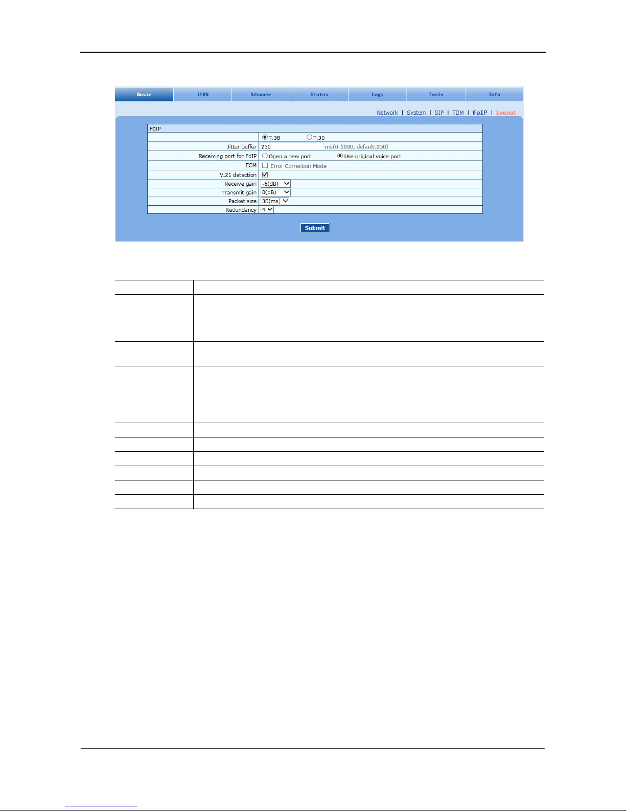
After login, click Basic > FoIP tab to open the configurati on in terface .
Page 29
MX100E SIP-ISDN Gateway Series User Manual
www.newrocktech.com 5-9
Figure 5-6 FoIP Configuration Interface
Table 5-7 FoIP Configuration Parameters
Name Description
Both T.38 and T.30 fax services are supported. It’s recommended to use T.38 fax services.
For T.30, no other parameters need to be configured.
For T.38, parameters available are as follows
Jitter buffer
Set the extent of T.38 jitter buffer, and the default is 250. The valid range is 0 ~ 1000 in
milliseconds.
Receiving port for
FoIP
Set whether to open a new port when the gateway is switching to T.38 mode, and by default,
original voice port will be used.
Open a new port: Use the new RTP port;
Use original voice port: Use the original RTP port that created on call set.
ECM Determine whether to use corrective mode of fax. By default, it is not selected.
V.21 detection Choose whether to enable V.21 signal detection. The function is enabled by default.
Receive gain Set the receiving gain of T.38 fax, with the default of -6dB.
Transmit gain Set the transmission gain of T.38 fax, with the default of 0dB.
Packet size Set the packet size of T.38. 30 milliseconds is the default value.
Redundancy Set the number of the redundant frames in T.38 data package, default is 4.
5.3.6 ISDN
In case of full configurations, the MX100E has one 4T1/E1 card, with four interfaces numbering ISDN1
to ISDN4 from left to right. You are recommended to set parameters corresponding to the interface
configured. Parameters for each interface are identical. You can set different parameter values for each
interface as needed. For parameter setting, take the ISDN1 as an example.
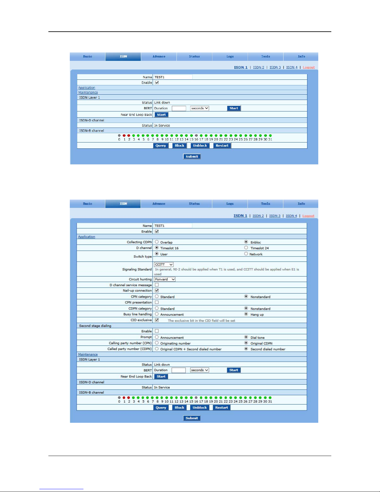
After login, click ISDN > ISDN1 tab to open the configuration interface.
Page 30
User Manual MX100E SIP-ISDN Gateway Series
5-10 www.newrocktech.com
Figure 5-7 ISDN Configuration Interface 1
If it’s necessary to configure link data, click Application to display the following configuration page:
Figure 5-8 ISDN Configuration Interface 2
Page 31

MX100E SIP-ISDN Gateway Series User Manual
www.newrocktech.com 5-11
Table 5-8 ISDN Configuration Parameters
Name Description
Name
Display the name of an ISDN interface.
Enable
Enable an ISDN interface.
Application
Collecting CDPN
Choose a collecting mode: Overlap or En-bloc.
D channel
A signalling channel. The default value is timeslot 16 for E1 services and timeslot 24
for T1 services.
Switch type
Set the interface protocol on the user side or network side. If the opposite terminal uses
network side, the local terminal should choose user side.
Signaling Standard
The variation of ISDN PRI signalling standards: CCITT, NI-2, DMS100, DMS250 and
5ESS.
You are recommended to select NI-2 for T1 card and CCITT for E1 card.
Circuit hunting
Search mode of idle timeslot: Forward, Backward and Cycle. Users can choose from the
drop-down box.
Forward: In the case of an incoming call, the MX100E first checks whether timeslot
1 is idle. If not, the MX100E checks whether timeslot 2 is idle. The process
proceeds in the ascending order until an idle timeslot is found.
Backward: The MX100E searches for an idle timeslot in the descending order.
Cycle: The MX100E searches for the next idle timeslot from left to
right.
D channel service message
Setting for enabling the D channel service message.
Nail-up connection
Setting for enabling P2P connection (the called party number and channel ID are not
required).
CPN category
Setting the Standard CPN calling party number category subfield. For the details, please
refer to the ITU-T Q.931 protocol.
CPN presentation
Setting CPN calling party number presentation subfield. For the details, please refer to
the ITU-T Q.931 protocol.
CDPN category
Setting the Standard CDPN called party number category subfield.
Busy line handing
The call processing mode for busy line is Announcement or Hang up.
CID exclusive
For the opposite terminal to change the line, choose Exclusive in CID.
Second stage dialing
Enable
Enable the second dial tone and detect the DTMF number.
Prompt
Set the mode of second dial tone: Announcement or Dial tone.
Calling party number(CPN)
Set the display mode of calling party number: Originating number or Original CDPN.
Called party number
(CDPN)
Set the display mode of called party number: Original CDPN + Second dialled number
or Second dialled number.
Maintenance
Page 32
User Manual MX100E SIP-ISDN Gateway Series
5-12 www.newrocktech.com
Name Description
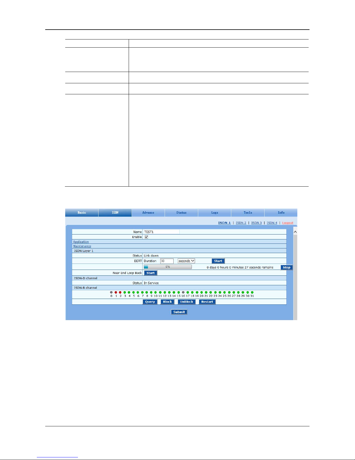
BERT
Set the duration, in the unit of seconds, minutes, hours, or days. After that, you can click
Start to view the progress bar and the Stop button, as shown in the following figure.
You can click Stop to cancel the testing process.
Near End Loop Back
Enable the loop back function for the remote device by clicking Start.
ISDN-D channel
Display the state of the ISDN-D channel: In service or Out of service.
ISDN-B channel
Displays the indicator state of a specific ISDN-B channel.
If you click the channel in green, the indicator turns yellow and the call from IP to
ISDN on the T1/E1 line is prohibited. The call from ISDN is not affected.
If you click Block and choose a specific channel, the indicator of the chosen
channel turns red.
If you click Unblock and choose a blocked channel, the indicator of the chosen
indicator turns green.
If you click Query and choose a channel, the channel state is refreshed.
If you click Restart and choose a channel, the choose channel restarts.
Figure 5-9 ISDN configuration Interface 3
5.4 Advanced Configuration
5.4.1 Routing Table
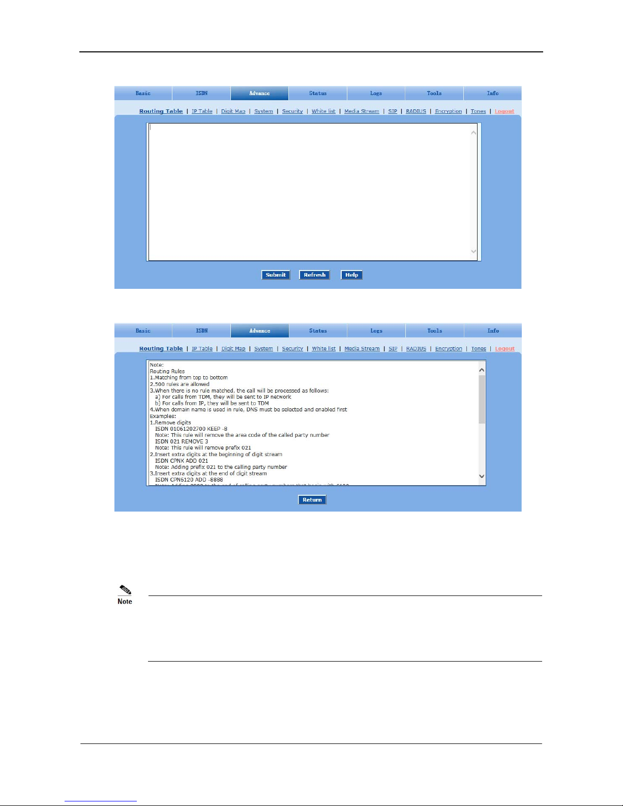
After login, click Advanced > Routing Table tab to open the configuration interface.
Page 33
MX100E SIP-ISDN Gateway Series User Manual
www.newrocktech.com 5-13
Figure 5-10 Configuration Interface for Routing Table
Click Help to open the illustrative interface for routing configuration
The routing table with 500 rules in capacity provides two functions including digit transformation and call
routing assignment. Here are the general rules applied by gateways when executing the routing table.
Rules must be filled out without any blank at the beginning of each line; otherwise the data can’t be
validated even if the system prompts successful submittal.
The routing table is empty by default. The gateways will point a call to the SIP proxy server when
there is no matched rule for the call.
The format of number transformation is
Source Number Handle [Parameter]
Or
Page 34

User Manual MX100E SIP-ISDN Gateway Series
5-14 www.newrocktech.com
Source Number ROUTE Destination [Parameter]
The format of number transformation is
Source Number Replacement Method
For example: FXS 021 REMOVE 3 means remove the prefix 021 of the called number for calls from
the IP.
The format of routing rules is:
Source Number ROUTE Destination
For example:
IP 8621 ROUTE ISDN 1
Indicates that the call with the called party number starting with 8621 is sent from the IP network to the
first E1 interface.
Detailed definitions of source and number, number transformation methods and routing destination are
shown below.
Table 5-9 Routing Table Format
Name Description
Source
Source can be ISDN or IP. When source is IP, an address can optionally be specified, e.g.,
[xxx.xxx.xxx.xxx] or [xxx.xxx.xxx.xxx:port].
There are two source types: IP and ISDN.
The IP source can be any of the following:
Any IP address, represented by IP.
A specified IP address, represented by IP[xxx.xxx.xxx.xxx].
A specified IP address and port number, represented by IP[xxx.xxx.xxx.xxx:port] (port
specifies a source port number, such as 5060).
Number
It could be a calling party number with the form of CPN + number, such as CPN6034340633 or
a called party number with the form of number. The number may be denoted with digit 0-9,
“*”, “.”, “#”, “x”, etc., and uses the same regular expression as that of dialing rules. Here are
examples of the form of number:
Designate a specific number: eg.114, 61202700
Designate a number matching a prefix: such as 61xxxxxx. Note: the matching effect of
61xxxxxx is different from that of 61x or 61. Number matching follows the principle of
minimum priority matching
Specify a number scope. For example, 268[0-1, 3-9] specifies any 4-digit number starting
with 268 and followed by a digit between 0-1or 3-9
Note: Number matching follows the principle of minimum matching. For example: x matches
any number with at least one digit; xx matches any number with at least two-digit; 12x matches
any number with at least 3-digit starting with 12.
Page 35

MX100E SIP-ISDN Gateway Series User Manual
www.newrocktech.com 5-15
Table 5-10 Number Transformations
Processing Mode Description and Example
KEEP
Keep number. The positive number behind KEEP means to keep several digits in front of the
number; the negative number means to keep several digits at the end of the number.
Example: IP 02161202700 KEEP -8
Keep the last 8 digits of the called number 02161202700 for calls from IP. The transformed
called number is 61202700.
REMOVE
Remove number. The positive number behind REMOVE means to remove several digits in the
front of the number; the negative number means to remove several digits at the end of the
number.
For example: IP 021 REMOVE 3
Any number start with 021, the 021 prefix is removed.
ADD
Add prefix or suffix to number. The positive number behind ADD is the prefix; the negative
number is suffix.
Example 1:
IP CPN6120 ADD 021
CPN number start with 6120, prefix 021 is added.
Example 2:
IP CPN6120 ADD -8888
CPN number start with 6120, 8888 is appended.
REPLACE
Number replacement. The replaced number is behind REPLACE.
Example:
ISDN CPN88 REPLACE 2682000
CPN number started with 88, the prefix “88” is replaced with 2682000.
Other use of REPLACE is to replace the specific number based on other number associated
with the call. For example, replacing the calling party number according to the called party
number.
Examples:
ISDN 12345 REPLACE CPN-1
Indicates that the tail digit is deleted from the caller number in correspondence with the called
party number 12345 from ISDN.
END or ROUTE
End of number transformation. From top to bottom, number transformation will be stopped
when END or ROUTE is encountered; the gateways will route the call to the default routing
after meeting END, or route the call to the designed routing after meeting ROUTE.
Example 1:
IP 12345 ADD -8001
IP 12345 REMOVE 4
IP 12345 END
Indicates that the called party number from an IP network starting with 12345. The first order
indicates it is suffixed with 8001, the second order indicates it removes 4 digits and the third
order indicates it ends the previous operations.
Example 2:
IP[222.34.55.1] CPNX REPLACE 2680000
IP[222.34.55.1] CPNX HIDE
IP[222.34.55.1] CPNX ROUTE ISDN 2
Indicates that any calling party number from the IP address 222.34.55.1 is replaced by 2680000.
The calling party number is hidden and the call is sent to the second E1.
Note: The hiding of the calling party number can be enabled only when the operator can
provide the corresponding support as well.
Page 36

User Manual MX100E SIP-ISDN Gateway Series
5-16 www.newrocktech.com
Processing Mode Description and Example
CODEC
Designate the use of codec, such as PCMU/20/16, where PCMU denotes G.711, /20 denotes
RTP package interval of 20 milliseconds, and /16 denotes echo cancellation with 16
milliseconds window. PCMU/20/0 should be used if echo cancellation is not required to
activate.
Example:
IP 6120 CODEC PCMU/20/16
PCMU/20/16 codec will be applied to calls from IP with called party number starting with
6120.
RELAY
Insert prefix of called party number when calling out. The inserted prefix number follows
behind REPLAY.
Example:
IP 010 RELAY 17909
For calls from IP with called party number starting with 010, digit stream 17909 will be
outpulsed before the original called party number is being sending out.
SEND180
Force send 180 on ring back
Example: IP CPN2 SEND180
CPN number start with 2, always send 180 on ring back.
SEND183
Force send 183 on ring back.
Example: IP CPN3 SEND183
CPN number start with 3, always send 183 on ring back (voice cut through).
HIDE
Calling party number presentation.
Example:
IP[61.2.44.53:5060] CPNX HIDE
Any call from 61.2.44.53:5060, calling party number presentation restriction is applied.
Note: The hiding of the calling party number can be enabled only when the operator can
provide the corresponding support as well.
Table 5-11 Routing Destination
Destination Description and Example
ROUTE NONE
Calling barring.
Example:
IP CPN[1,3-5] ROUTE NONE
Bar all calls from IP, of which the calling numbers start with 1, 3, 4, 5.
ROUTE ISDN
Route a call to ISDN.
IP 8621 ROUTE ISDN 1
IP CPN8620 ROUTE ISDN 2
call has 8621 prefix, route to ISDN span 1
calling party number started with 8620, route to ISDN span 2
ROUTE IP
Route a call to the IP platform.
Example:
FXS 021 ROUTE IP 228.167.22.34:5060
228.167.22.34:5060 is the IP address of the platform.
ISDN 021 ROUTE IP 228.167.22.34:5060
ISDN 020 ROUTE IP 61.234.67.89:5060
Indicates that the call from the PSTN, with the called party number starting with 021 will be sent
to the platform with the IP address of 228.167.22.34; the call with the called party number
starting with 020 will be sent to the platform with the IP address of 61.234.67.89.
5.4.2 Application Examples of Routing Table
Application requirements
Page 37
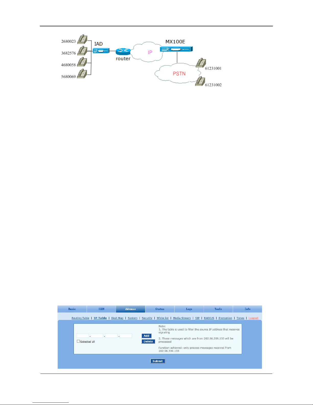
MX100E SIP-ISDN Gateway Series User Manual
www.newrocktech.com 5-17
Selecting an E1 line based on calls from the IP network.
Replacing the calling party number section of an IP call with a shared number.
Permitting the IP call with the number only in the calling party number section, not other ID
sections.
Hiding the calling party number of an IP call by replacing the entire calling party number section
with one digit number.
Specifying a voice coding for a certain kind of clients.
Routing setting
IP CPNX REPLACE 18710095 (B)
IP CPN2 CODEC PCMU/20/64 (E)
IP CPNX HIDE (D)
IP[221.38.112.26] CPN2 ROUTE ISDN 3 (A)
IP CPN[1,4-5] ROUTE NONE (C)
Calls from 2680023 to 61231001 are matched with configurations of (B), (E), (D), and (A). The
calling party number 2680023 is replaced with 18710095, with the codec of pcmu/20/64. The calling
party number is hidden and the call is sent to the third E1 line.
Calls from 3682576 calls 61231002 are matched with configurations of (B) and (D). The calling
party number 3682576 is replaced with 18710095 and is then hidden. Configurations (A), (E), and
(C) are not matched.
Calls from 4680058 and 5680069 to 61231001 are matched with the configuration (C), and calls are
prohibited.
5.4.3 IP Table
After login, click Advanced > IP Table tab to open the configuration interface.
Figure 5-11 Configuration Interface for IP Table
Page 38
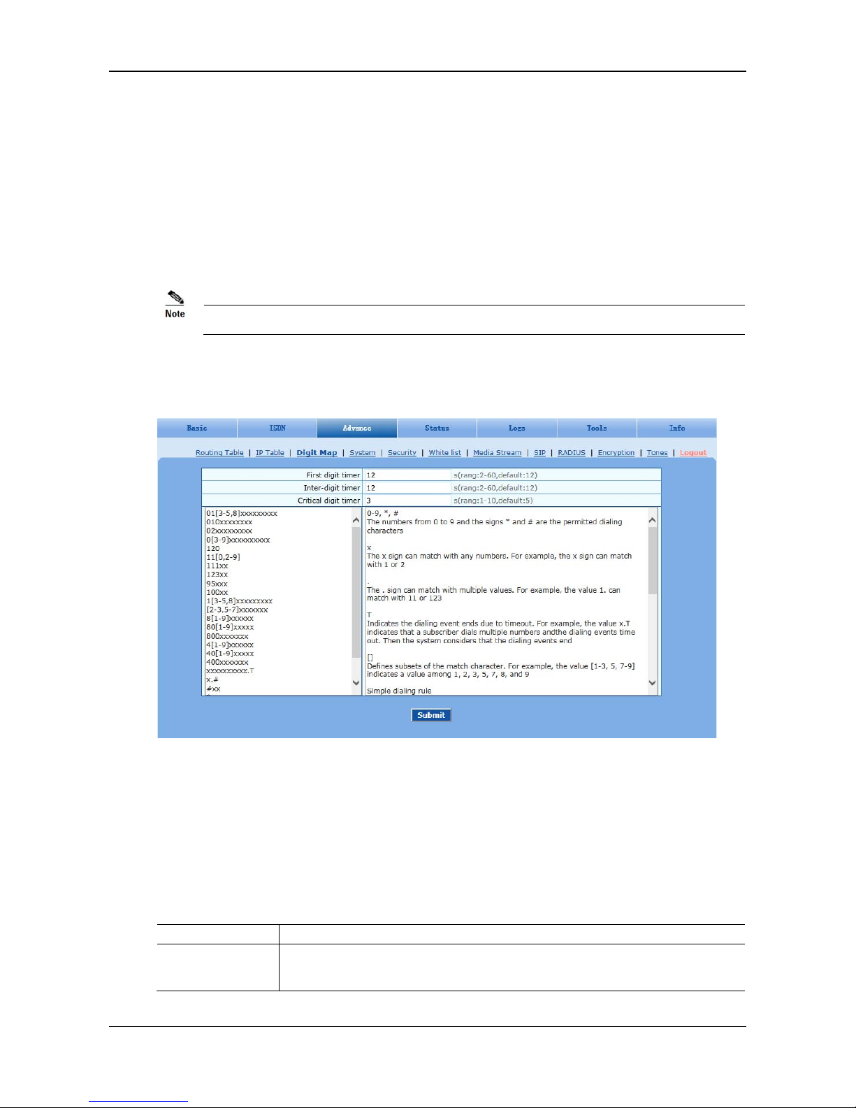
User Manual MX100E SIP-ISDN Gateway Series
5-18 www.newrocktech.com
This table is designed to ensure the safe use of gateways. Administrators can add the authorized IP
addresses to this table, and the gateways will only process the information from authorized IP addresses.
If the IP table is empty, the gateways will not perform IP address-based message filtering.
For example: the gateway will only process the messages from 202.96.209.133 after adding
202.96.209.133 to its IP table.
5.4.4 Digit Map
In most situations, dialing rules need to be configured only for second dial on the MX100E.
After login, click Advanced > Digit Map tab to open the dialing rules interface.
Figure 5-12 Configuration Interface for Digit Map
Dialing rules are used to effectively judge if the received number sequence is completed, for the purpose
of ending up receiving numbers and sending out the received numbers. The proper use of dialing rules
can help to reduce the connection time of telephone calls.
The maximum number of rules that can be stored in gateways is 520. The total length of dialing rules
table (the total length of all dialing rules) cannot be more than 3000 bytes.
The following provides a description of typical rules:
Table 5-12 Description of Digit map
Digit map Description
First digit timer
If a subscriber hasn’t dialed any number within a specified time by this parameter after
offhook, the gateways will consider that the subscriber has given up the call and prompt to
hang up in busy tone. Unit: second, default value: 12 seconds.
Page 39

MX100E SIP-ISDN Gateway Series User Manual
www.newrocktech.com 5-19
Digit map Description
Inter-digit timer
If a subscriber hasn’t dialed the next number key from the time of dialing the last number key
to the set time by this parameter, the gateways will consider that the subscriber has ended
dial-up and call out the dialed number. The default value is 12 seconds, unit: second.
Critical digit timer
This parameter is used with the “x.T” rule set in dialing rules. For example, there is “021.T” in
the dialing rules table. When a subscriber has dialed 021 and hasn’t dialed the next number
within a set time by this parameter (e.g. 5 seconds), the gateways will consider that the
subscriber has ended dial-up and call out the dialed number 021.
The default value is 5 seconds, unit: second.
x Represents any number between 0-9.
The x sign can match with any numbers. For example, the x sign can match with 1 or 2.
. Represents more than one digit between 0-9.
The sign can match with number with any length. For example, the value 1. can match with 11
or 123.
##
End after receiving two-digit dialing “##”. “##” is a special dialing for users to receive
gateway IP address and version number of firmware by default.
x.T
The gateways will detect any length of telephone number starting with any number between
0-9. The gateways will send the detected number when it has exceeded the dialing end time set
in system parameter configuration and hasn’t received a new number.
x.#
Any length of telephone number starting with any number between 0-9. If subscribers press #
key after dial-up, the gateways will immediately end up receiving numbers and send all the
numbers before # key.
*xx
End after receiving * and any two-digit number. “* xx” is primarily used to activate function
keys for supplementary services, such as CRBT, Call Transfer, Do not Disturb, etc.
#xx
End after receiving # and any two-digit number. “#xx” is primarily used to stop function keys
for supplementary services, such as CRBT, Call Transfer, Do not Disturb, etc.
[2-8]xxxxxx A 7-digit number starting with of any number between 2-8, used to end the dialing.
02xxxxxxxxx A 11-digit number starting with 02, used to end the dialings starting with “02”.
13xxxxxxxxx A 11-digit number starting with 13, used to end the dialings.
11x A 3-digit number starting with 11, used to end the special service calls.
9xxxx A 5-digit number starting with 9, used to end special service calls.
17911 (used as an
example)
The MX100E sends out the call with a specified number (such as 17911) immediately after
receiving it. This example is used to demonstrate how the MX100E handles calls with a
specified number.
Dial rules by default as follows:
01[3, 5, 8] xxxxxxxxx
010xxxxxxxx
02xxxxxxxxx
0[3-9] xxxxxxxxxx
120
11[0, 2-9]
111xx
123xx
95xxx
100xx
1[3-5, 8] xxxxxxxxx
[2-3, 5-7] xxxxxxx
Page 40
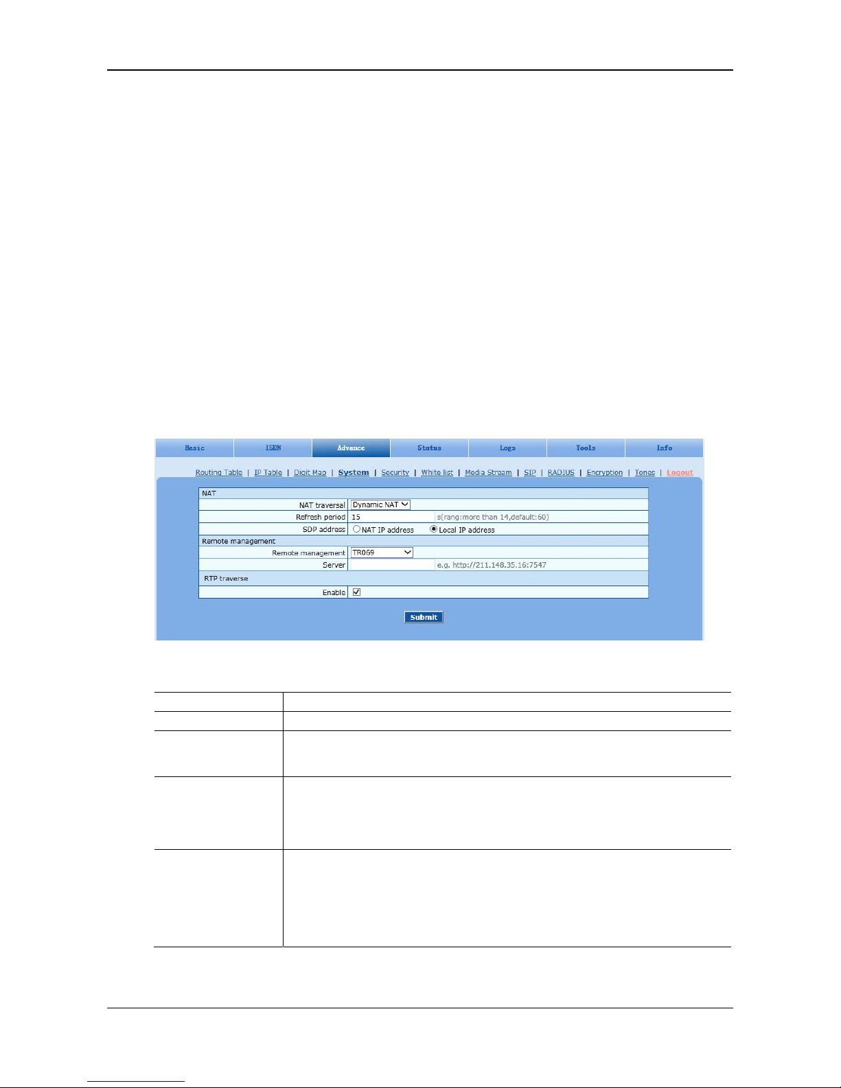
User Manual MX100E SIP-ISDN Gateway Series
5-20 www.newrocktech.com
8[1-9] xxxxxx
80[1-9] xxxxx
800xxxxxxx
4[1-9] xxxxxx
40[1-9] xxxxx
400xxxxxxx
xxxxxxxxxx.T
x.#
#xx
*xx
##
5.4.5 System
After login, click the label of Advanced > System to open this interface.
Figure 5-13 System Advanced Configuraiton Interface
Table 5-13 Advanced System Configuration Parameters
Name Description
NAT
NAT traversal
Gateways support several mechanisms for NAT traversal. Usually, static NAT is used when
fixed public IP address is available. It’s necessary to perform port mapping or DMZ function
on router when choosing dynamic or static NAT.
Refresh period
The refresh time must be filled in here when choosing dynamic NAT or STUN traversal.
Besides, refresh time interval shall be determined by giving consideration into the NAT
refresh time of the LAN router which the gateway is located. Gateway’s NAT holding
function and STUN function will carry out periodically operation according to this
parameter. With second as its unit, default value of 60 seconds.
SDP Address
This parameter determines the IP address used in transmitted SDP.
NAT IP Address: Apply NAT address into the transmitted SDP;
Local IP Address: Apply the gateway’s IP address into the transmitted SDP.
Note: The parameter should come into effect only on condition that gateway successfully
obtained NAT address.
Page 41
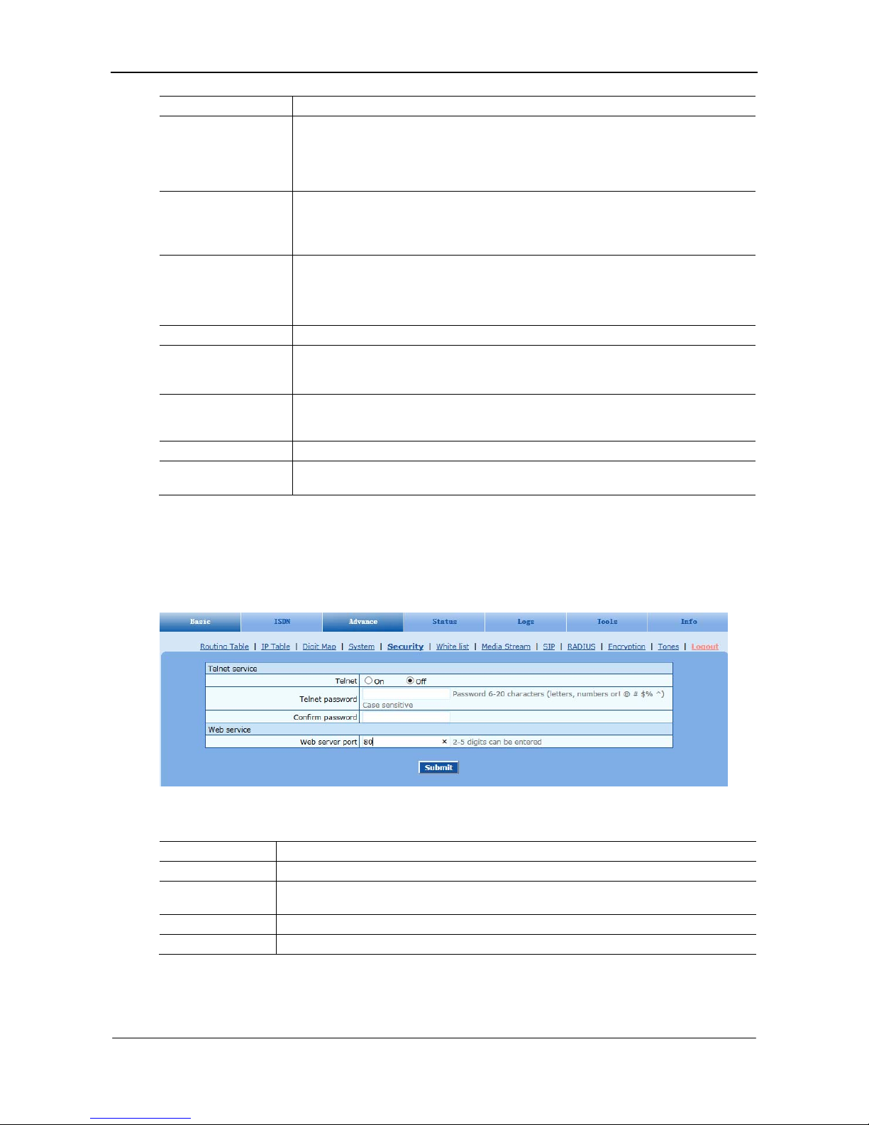
MX100E SIP-ISDN Gateway Series User Manual
www.newrocktech.com 5-21
Name Description
NAT IP address
This parameter must be filled when using static NAT traversal, in which IAD works under
LAN and the WAN address is fixed. The WAN address should be filled in this field, which
will be used in SDP. This parameter can be set in IP address format or hostname format
(note: DNS service should be activated when hostname format is used). There is no default
value for this field.
STUN server
Set the IP or domain name of STUN server. No default value. If the set is empty, the
gateway will adopt the STUN server address configured at factory.
When choosing STUN for NAT traversal, the gateway will carry out STUN operation
periodically according to the configured interval time of NAT refresh.
RTP Receiving Port
The gateways will send the RTP receiving port selected here to the remote side.
NAT port: Use NAT mapped port,which is obtained through STUN, for example;
Local port: Use local SIP and RTP port.
Remote management
Remote management
TR069
Auto Provision
Server
Gateways may download software upgrade packages and configuration files automatically
through auto-provision server. Once the auto provision is selected, you have to enter the IP
address of ACS here.
Remote management
Remote management
The gateways support EMS which is a centralized gateway management server provided by
New Rock, and Auto-provision.
5.4.6 Security
After login, click Advanced > Security tab to open this interface.
Figure 5-14 Security Configuration Interface
Table 5-14 Security Configuration Parameters
Name Description
Telnet Choose whether to enable the Telnet function.
Telnet password
The Telnet password consists of 6-20 bit case-sensitive characters (letters, digits, or marks such
as !, @, #, $, %, and ^).
Confirm password Re-input the Telnet password.
Web server port Specifies the port number of the Web server. The value is a 2-4 bit digit number.
Page 42
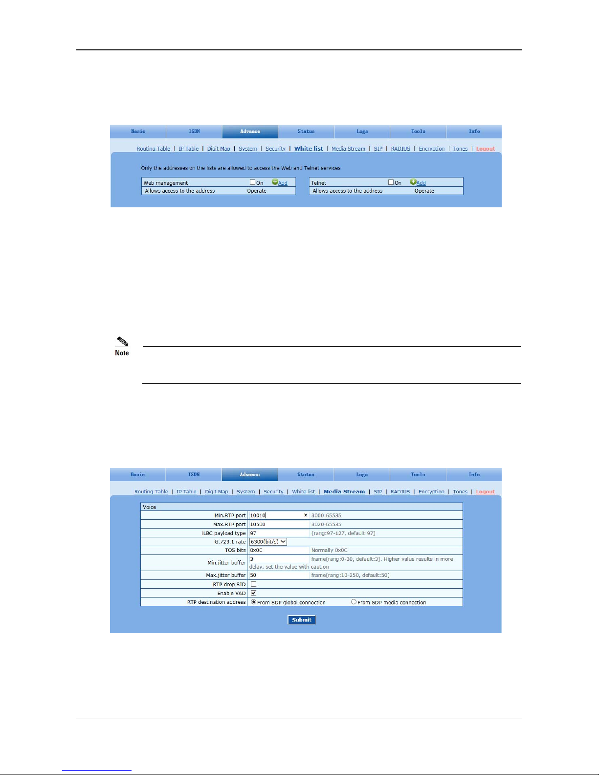
User Manual MX100E SIP-ISDN Gateway Series
5-22 www.newrocktech.com
5.4.7 White List
After login, click Advanced > White list tab to open this interface.
Figure 5-15 White List Configuration Interface
Procedures for configuring the whitelist are as follows (the Web management configuration is used as
an example):
Step1 Click Add.
Step2 Enter the address allowed to access in the dialog box displayed, and click OK.
Step3 Tick off On.
This function takes effect after the system reboots.
The maximum 20 entries can be added to the whitelist on the MX100E.
5.4.8 Media Stream
After login, click the label of Advanced > Media Stream to open this interface.
Figure 5-16 Media Stream Configuration Interface
Page 43

MX100E SIP-ISDN Gateway Series User Manual
www.newrocktech.com 5-23
Table 5-15 Media Stream Configuration Parameters
Name Description
Min. RTP port
The minimum value of UDP ports for RTP transmission and receiving, and the parameter
must be greater than or equal to 3000.
The value is recommended to be equal or greater than 10000.
Note: each phone call will occupy RTP and RTCP ports.
Max. RTP port The maximum values of UDP ports for RTP’s transmission and receiving.
It’s advisable to be greater than or equal to “2× number of lines + min. RTP port”.
iLBC payload type
Set the RTP payload type of iLBC, and the default value is 97. Accepted value is 97-127.
The parameter shall be configured in conformity to that of platform.
G.723.1 rate
Set G.723.1 coding rate,the default value is 6300. The optional parameters are followings:
5300: the Bit rate is 5.3k per second;
6300: the Bit rate is 6.3k per second
TOS bits
This parameter specifies the quality assurance of services with different priorities. The
factory setting is 0x0C.
For example, TOS=0xB8 indicates that the priority of the service quality is 5, with a
requirement on low delay and high throughput. There is no requirement on the reliability.
Min. Jitter buffer
RTP Jitter Buffer is constructed to reduce the influence brought by network jitter. This
default value is 3.
Max. Jitter buffer
RTP Jitter Buffer helps to reduce the influence brought by network jitter. The default value
is 50.
RTP drop SID
Determine whether to discard received RTP SID voice packets. By default, SID voice
packets will not be dropped.
Note: RTP SID packets should be dropped only when they are in unconformity to the
specifications. Nonstandard RTP SID data could generate noise for calls.
Enable VAD
Only applicable to G.723, GSM, iLBC. In case of selecting this parameter, it will not send
any voice packet during mute period. By default, this is selected.
RTP destination address
This parameter determines where to obtain the IP address of the receiving side for RTP
packets. By default, the IP address is obtained “From SDP global connection”.
From SDP global connection: Obtain the IP address from SDP global connection;
From SDP media connection: Obtain the IP address from SDP Media Description.
5.4.9 SIP Related Configuration
After login, click the label of Advanced > SIP to open this interface.
Page 44
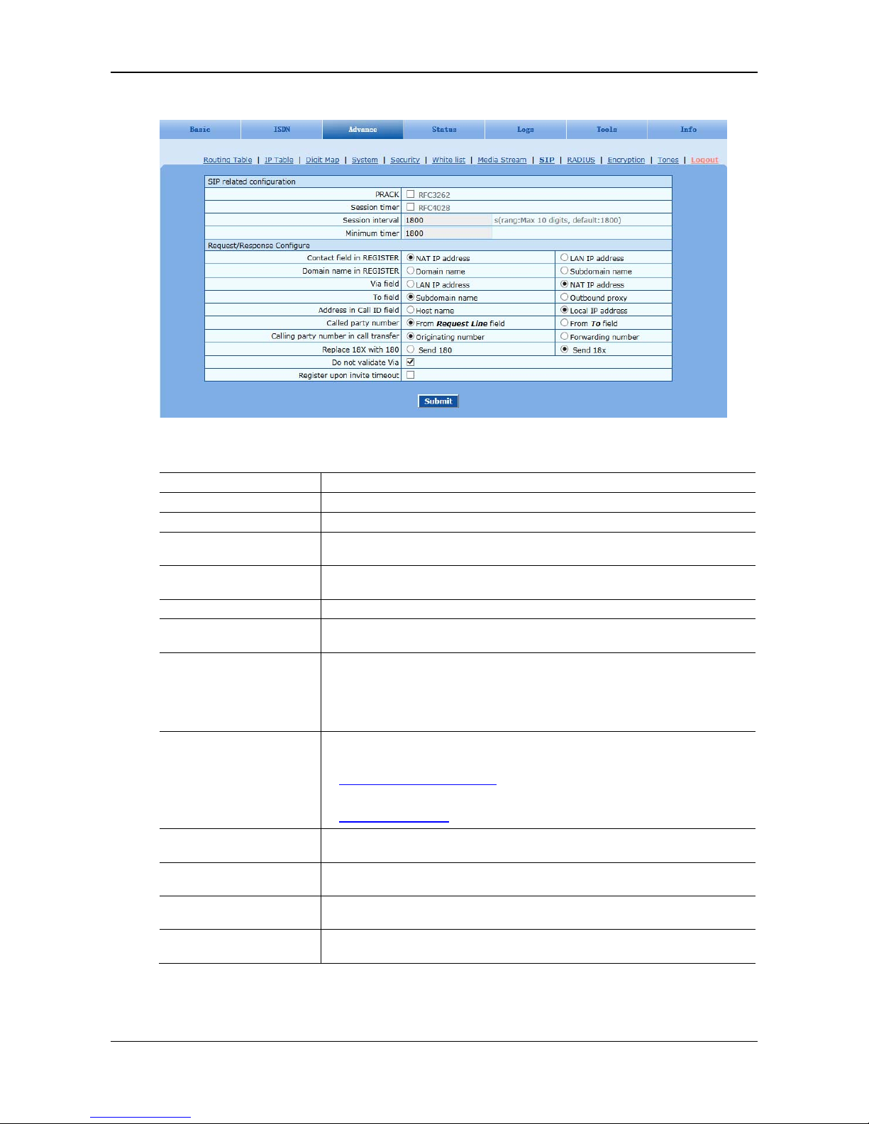
User Manual MX100E SIP-ISDN Gateway Series
5-24 www.newrocktech.com
Figure 5-17 SIP Related Configuration Interface
Table 5-16 SIP Related Configuration Parameter
Name Description
SIP related configuration
PRACK Determine whether to activate Reliable Provisional Responses. (RFC 3262)
Session timer
Choose to activate session refresh (Session Timer, RFC 4028). By default, session
timer is not activated.
Session interval
Set the session refresh interval, the gateway will enclose the value of Session-Expires
into INVITE or UPDATE messages. Default value is 1800 in second.
Minimum timer Set the minimum value of session refresh interval.
Request/Response
Configure
Contact field in REGISTER
Choose the registration mode of gateway under LAN traversal circumstance, the
default is NAT IP Address.
LAN IP address: Keep original content of Contact when register;
NAT IP address: Use the NAT information returned by registration server.
Domain name in REGISTER The default is Domain name.
Domain name: Complete domain name used for registration (for example:
);
Subdomain name: Only use the common part of the name of domain (for example:
).
Via field
Choose whether to use NAT IP address or LAN IP address for “Via” header field
value, the default is NAT IP address.
To field
Choose whether to apply Domain name or Outbound proxy to “To” header field, the
default is Domain name.
Address in Call ID field
Choose whether to fill Call ID field with host name or local IP, the default is local IP
address.
Called party number
Choose whether the gateway acquires the called number from Request Line header
field or To header field. The default is from Request Line.
Page 45
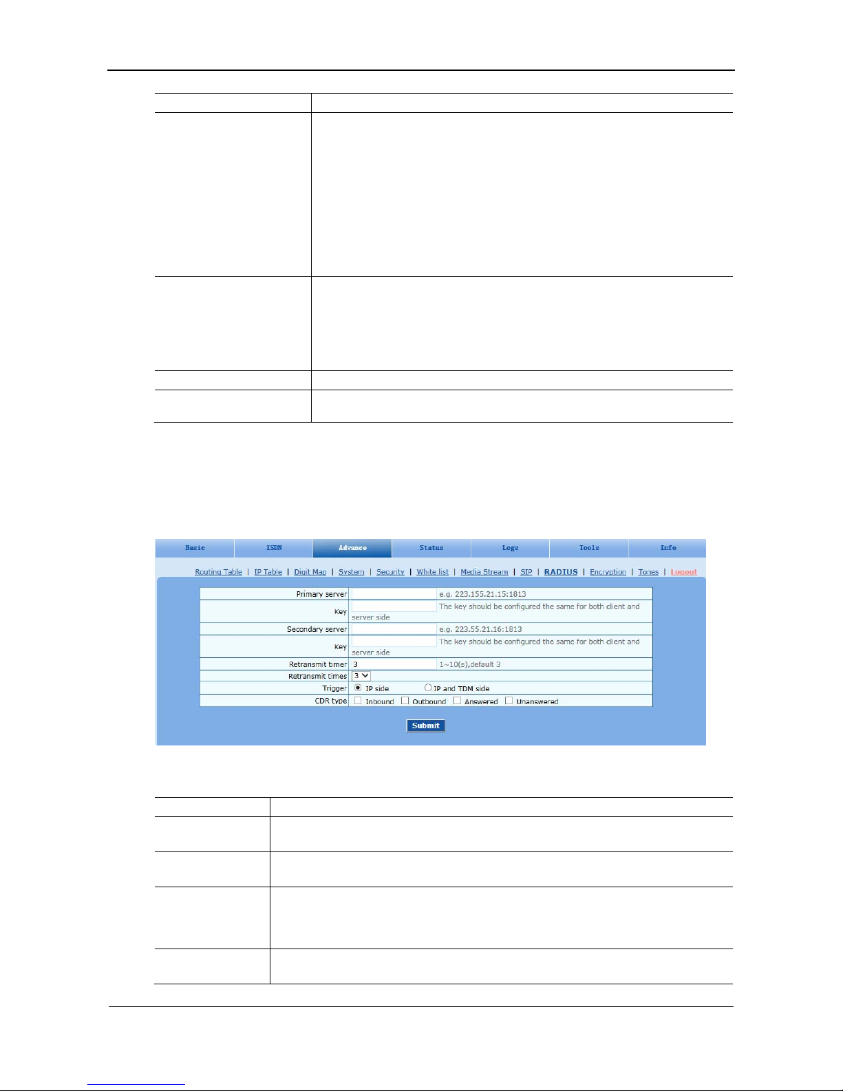
MX100E SIP-ISDN Gateway Series User Manual
www.newrocktech.com 5-25
Name Description
Calling party number in call
transfer
Under call forwarding, the calling party number sent can be choose from Originating
number or Forwarding number being set for sending, the default is Forwarding
number.
For example: the subscriber line 2551111 on the gateway activates call forwarding
feature and set the destination to 3224422. When caller with 13055553333 calls
2551111, the call will be forwarded to 3224422:
If choose Originating number, the number 13055553333 will be sent to 3224422
as calling party number.
If choose Forwarding number, the number 2551111 will be sent to 3224422 as
calling party number.
Replace 18X with 180
Send 180: If this parameter is set to enable, the gateway will map all alerting
messages (ALERTING with and without in-band indicator) to 180. An example of
when this parameter would be enabled is when an IAD does not support a 183
message.
Send 18x: If this parameter is set to enable, the 18x message will be sent.
Do not validate Via Set whether to ignore Via field, By default, Via is ignored.
Register upon INVITE
timeout
Set whether to activate registration when SIP message of INVITE is failed or time
expired, and by default, re-registration is not selected.
5.4.10 RADIUS
After login, click the label of Advanced > RADIUS to open this interface.
Figure 5-18 RADIUS Configuration Interface
Table 5-17 RADIUS Configuration Parameter
Name Description
Primary server Set IP address and port number of preferred Radius server.
Note: if the port number is not configured yet, please use Radius default port number of 1813.
Key Set the share key to be used for encrypted communications between Radius client and server.
Note: the share key should be configured the same for both client and server side
Secondary server
Set the IP address and port number of standby Radius server. When the fault appears in
communications between gateway and preferred Radius server, the gateway will automatically
activate standby Radius server.
Note: in case of no configuration of port number, use default port number of 1813.
Key The share key for communications between Radius client and standby Radius server.
Note: the key should be configured the same for both client and server side
Page 46
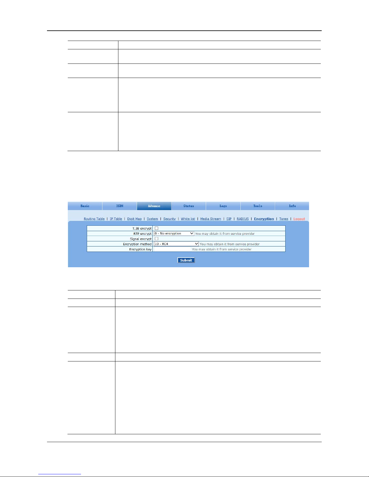
User Manual MX100E SIP-ISDN Gateway Series
5-26 www.newrocktech.com
Name Description
Retransmit timer
Set the amount of overtime on response after transmission of Radius message, the default is 3
seconds. The retransmission will be performed If no response is given after the timeout.
Retransmit times
Set the times of retransmission of Radius message when no response is received default is 3
times.
Trigger
IP side: when this is selected the call information on the SIP side will be sent to the Radius
server.
IP and TDM side: when this is selected the call information on the SIP side as well as on the
ISDN side will be sent to the Radius server.
CDR type
Outbound: Set whether to send RADIUS charge message for outbound calls;
Inbound: Set whether to send RADIUS charge message for inbound calls;
Answered: Set whether to send RADIUS charge message when calls are connected;
Unanswered: Set whether to send RADIUS charge message for unanswered calls.
5.4.11 Encryption
After login, click the label of Advanced > Encryption to open this interface.
Figure 5-19 Encryption Configuration Interface
Table 5-18 Encryption Configuration Interface
Name Description
T.38 encrypt Choose whether to encrypt T38 data. By default, this is not selected.
RTP encrypt Choose whether to encrypt RTP voice pack, the default is 0.
0: No encryption
1: Entire message
2: Header only
3: The data body only
Signal encrypt Choose whether to encrypt signaling. By default, this is not selected.
Encryption method Set the gateway encryption method, default is 8. The optional parameters as below:
10: RC4
14: Encrypt14
16: Word reverse(263)
17: Word exchange(263)
18: Byte reverse(263)
19: Byte exchange(263)
20:VOS
Page 47
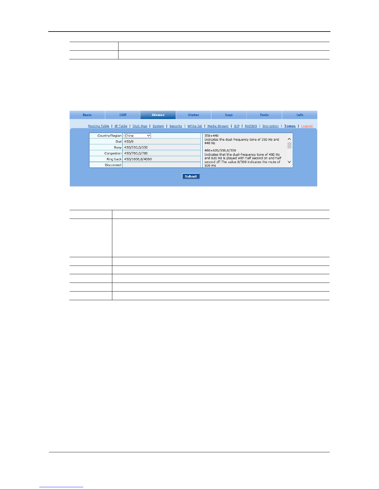
MX100E SIP-ISDN Gateway Series User Manual
www.newrocktech.com 5-27
Name Description
Encryption key You may obtain it from service provider.
5.4.12 Tones
After login, click the label of Advanced > Tones to open this interface.
Figure 5-20 Tones Configuration Interface
Table 5-19 Tones Configuration Parameters
Name Description
Country/region
There are progress tone plans for several countries and regions which are pre-programmed in
gateways. Users may also specify the tone plan according to the national standard. Gateways
provide tone plan for the following countries and regions:
China; the United States; France; Italy; Germany; Mexico; Chile; Russia; Japan; South Korea; Hong
Kong; Taiwan; India; Sudan; Iran; Algeria; Pakistan; Philippines; Kazakhstan;
Dial Prompt tone of off-hook dialup
Busy Used for busy line prompt
Congestion Used for notification of call set up failure due to resource limit
Ring back The prompt tone sent to caller when ring
Disconnect Used for reminding the subscriber of off-hook and no dialup status of the phone
Here are examples that illustrate the various call-progress tones
350+440 (dial tone)
Indicates the dual–frequency tone consisting of 350 and 440 Hz
480+620/500,0/500 (busy)
Indicates the dual–frequency tone consisting of 480 and 620 Hz, repeated playing with 500
milliseconds on and 500 milliseconds off.
Note: 0/500 indicates 500 milliseconds mute.
440/300,0/10000,440/300,0/10000
Indicates 440 Hz single frequency tone, repeated twice in terms of 300 milliseconds on and 10
seconds off.
950/333,1400/333,1800/333,0/1000
Indicates repeated playing 333 milliseconds of 950 Hz, 333 milliseconds of 1400 Hz, 333 milliseconds
of 1800 Hz, and mute of 1 second.
Page 48
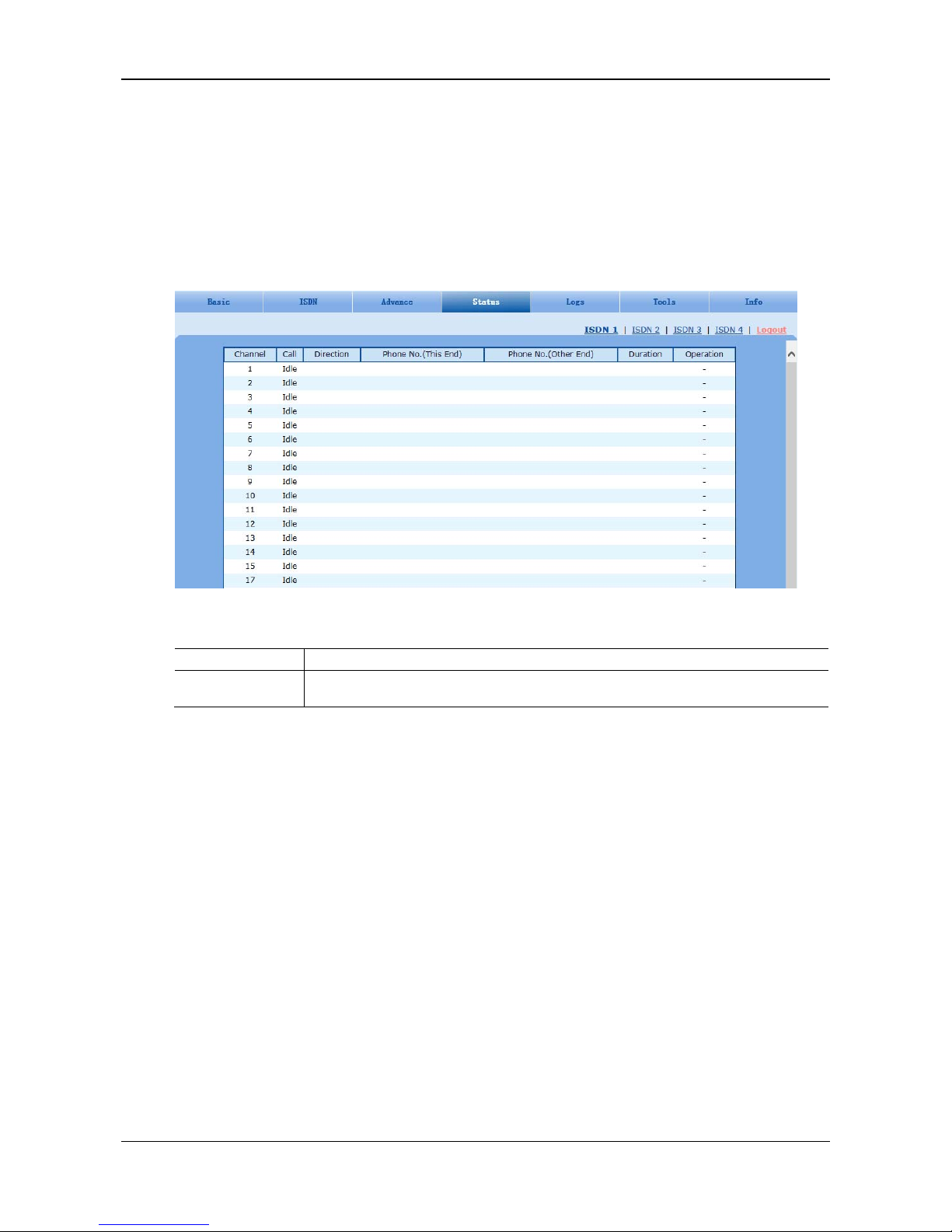
User Manual MX100E SIP-ISDN Gateway Series
5-28 www.newrocktech.com
5.5 Status
In case of full configurations, the MX100E has one 4T1/E1 card, with four interfaces numbering
ISDN1 to ISDN4 from left to right. Users can view the ISDN calling state on the interface in usage.
The calling information about ISDN (1) is used as an example.
After login, click Status > ISDN1 tab to open the interface.
Figure 5-21 ISDN Status Interface
Table 5-20 Status Parameters
Name Description
Call
The call state involves idle, outpulsing, ringing, dialling, initiating a call, ring back, talking,
on-hook on the local end, and on-hook on the opposite terminal.
5.6 Log Management
5.6.1 System Status
Critical runtime information of gateways can be obtaine d in this interface, includi ng:
The information about login interface (including IP address and permissions of the user)
SIP registration status
Call-related signaling and media (RTP) information
After login, click the label of Logs > System Status to open this interface.
Page 49
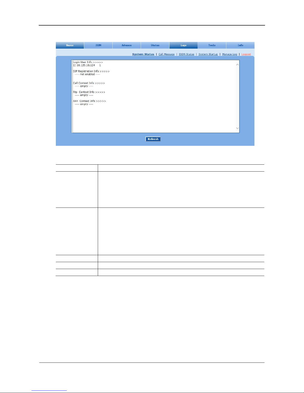
MX100E SIP-ISDN Gateway Series User Manual
www.newrocktech.com 5-29
Figure 5-22 System Status Interface
Table 5-21 System Status Parameters
Name Description
Login User Info
Show the IP address and jurisdiction of login user. The numbers following the IP address show
the online jurisdiction of the user: 1- administrator; 2 - operator; 3 – viewer. The viewer can
only read the configuration, but is not allowed to modify it.
When more than one administrator log in at the same time, the first login’s jurisdiction is 1,
others are 3; also, when more than one operators log in at the same time, the first one’s
jurisdiction is 2, others are 3.
SIP Registration Info
Show registration status:
Not enabled: The registration server’s address is not entered yet;
Latest response: The latest response message for the registration. 200 means
registered successfully;
No response: No response from registration server. The cause may contribute to 1)
incorrect address for the registration server; 2) IP network fault; or, 3) the
registration server is not reachable.
Call Context Info Show the call status.
Rtp Context Info Show the voice channel related to the calls.
Ann Context Info Display the playing voice message.
5.6.2 Call Message
After login, click the label of Logs > Call Message to open this interface.
Page 50
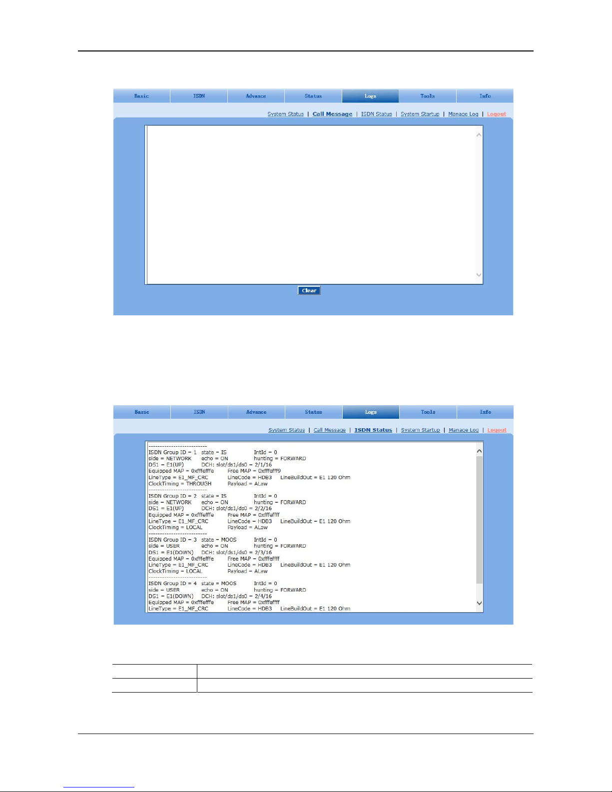
User Manual MX100E SIP-ISDN Gateway Series
5-30 www.newrocktech.com
Figure 5-23 Call Message Interface
5.6.3 ISDN Status
After login, click Logs > ISDN Status tab to open this interface.
Figure 5-24 ISDN Status Interface
Table 5-22 ISDN Status Parameters
Name Description
ISDN Group ID The ID of an ISDN group.
Page 51

MX100E SIP-ISDN Gateway Series User Manual
www.newrocktech.com 5-31
Name Description
state
State.
IS indicates the in-service state.
OOS indicates the out-of-service state.
MOOS indicates the manually taken-out-of service state, i.e. the backup signaling channel
is disabled.
Int Id The ID of an interface card, which is 0.
side
Two sides of the ISDN: user and network side, which must be set in pairs, with one side being
User and the other side being Network.
echo
The echo cancellation function.
On: indicates that the echo cancellation is enabled.
Off: indicates that the echo cancellation is disabled.
hunting
Two search modes of idle timeslot:
FORWARD
BACKWARD
DS1
The type of an interface card: T1 or E1. The connection state of the interface card can be:
UP
DOWN
slot/ds1/ds0
One of interfaces (represented by ds1) on a certain slot (represented by slot) into which the T1
or E1 interface card is inserted. ds0 specifies a signaling channel. The signaling channel for the
E1 card is 16 timeslots and the signaling channel for the T1 card is 24 timeslots .
Equipped MAP
The available state of the remaining 30 timeslots on the E1 card, except timeslots 0 and 16. If
the binary value in 0xfffefffe is 1, the timeslot is available.
Free MAP The state of an idle timeslot.
LineType
The frame format, including SF, D4, T1_UNFRAMED, SF, E1, E1_MF, E1_CRC and
E1_UNFRAMED.
LineCode The line code, including B8ZS, AMI, JBZS, HDB3, ZBTSI, B6ZS, JBZS, etc.
LineBuildOut The line build-out, which is 120 or 75 Ohm.
ClockTiming The clock source: Local or Through.
Payload The PCM encoding type: ALAW or ULAW.
5.6.4 System Startup
After login, click Logs > System Startup tab to open this interface. The gateway boot up information is
available in this page, including the hardware configuration.
Page 52
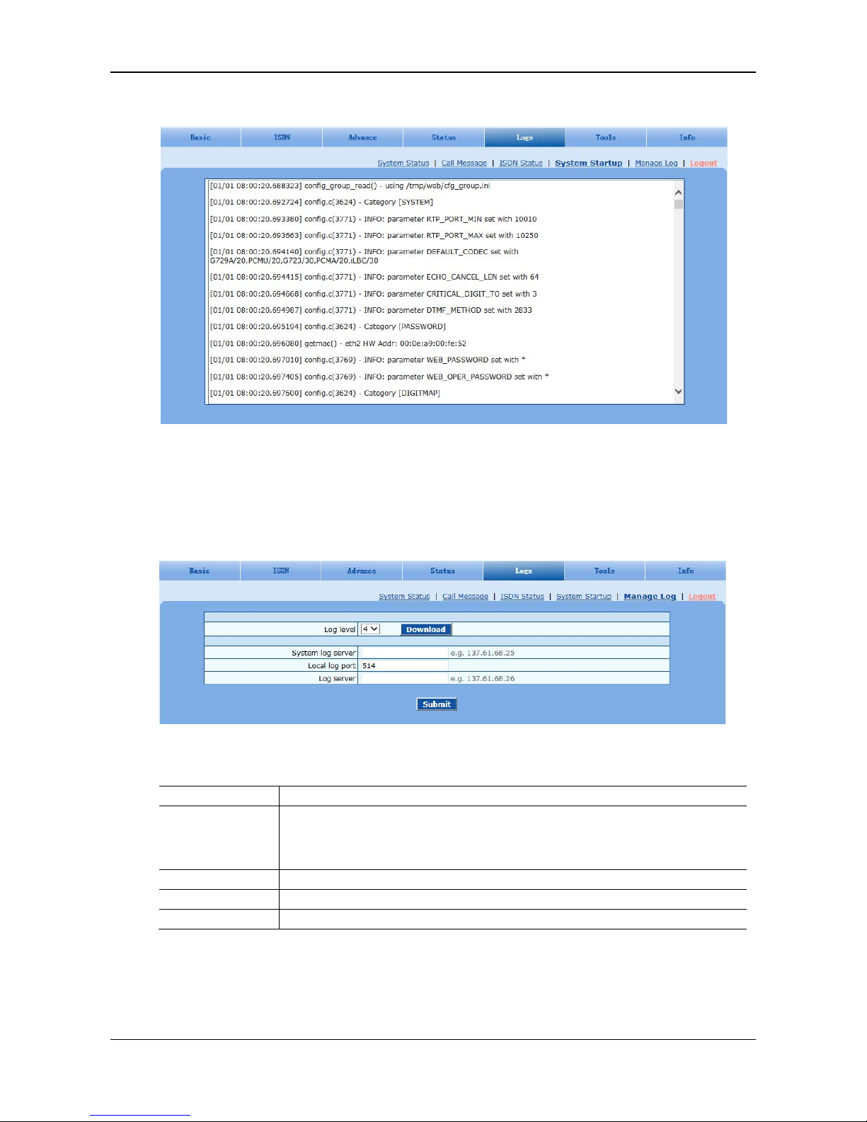
User Manual MX100E SIP-ISDN Gateway Series
5-32 www.newrocktech.com
Figure 5-25 System Startup Interface
5.6.5 Manage Log
After login, click the label of Logs > Manage Log to open this interface. Log files can be downloaded
through this interface.
Figure 5-26 Manage Log Interface
Table 5-23 Manage Log Parameters
Name Description
Log level
Select the log file level of gateway, default is 4. The higher the level goes, the more details the
log file will be.
Note: log level should be set to be 4 or lower when gateway is used in normal operation,
avoiding influencing the system performance.
System log server Set the IP address of system log server.
Local log port The port for sending system logs.
Log server IP address of debugging log server.
Procedure for downloading the log:
Step1 Click Download, the gateway begins to assemble the logs.
Step2 After a few seconds, the interface of log saving will appear.
Page 53
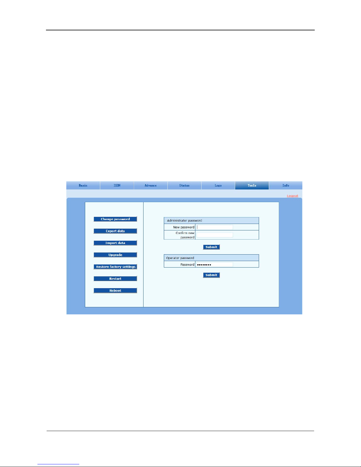
MX100E SIP-ISDN Gateway Series User Manual
www.newrocktech.com 5-33
Step3 Click Save, and select path to save.
Step4 The user may review the log from the server.
5.7 System Tool
5.7.1 Change Password
After login, click Tools to open this interface. Only administrator is entitled to change the password of
login.
For changing administrator password, it’s required to enter new password into New password field and
Confirm new password field, then click Submit.
The password being used by the operator will be displayed as hidden codes, which could be changed by
the administrator at any time. The administrator is allowed to change the operator’s password by
entering the new password into Operator password > password.
Figure 5-27 Change Password Interface
5.7.2 Configuration Export
After login, click Tools > Export data tab to open this interface. It’s allowed to download the
configuration files from the gateway through this interface. The downloading procedure is similar to the
downloading procedure of log files.
Page 54
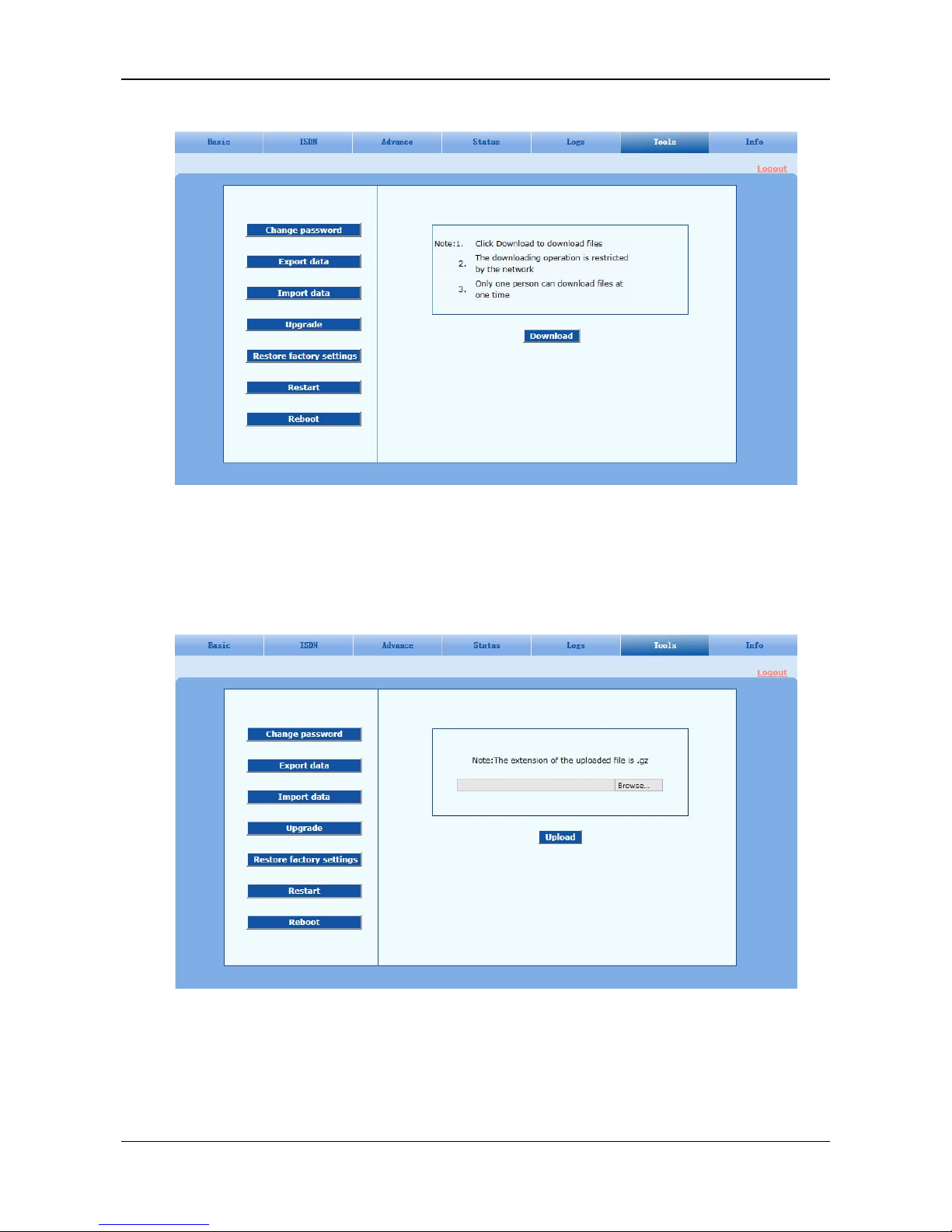
User Manual MX100E SIP-ISDN Gateway Series
5-34 www.newrocktech.com
Figure 5-28 Configuration Export Interface
5.7.3 Configuration Import
After login, click Tools > Import data tab to open this interface. Operating procedure is the same as that
of software upgrade.
Figure 5-29 Configuration Import Interface
5.7.4 Software Upgrade
After login, click Tools > Upgrade to open this interface. The software upgrading procedure is presented
as below:
Page 55
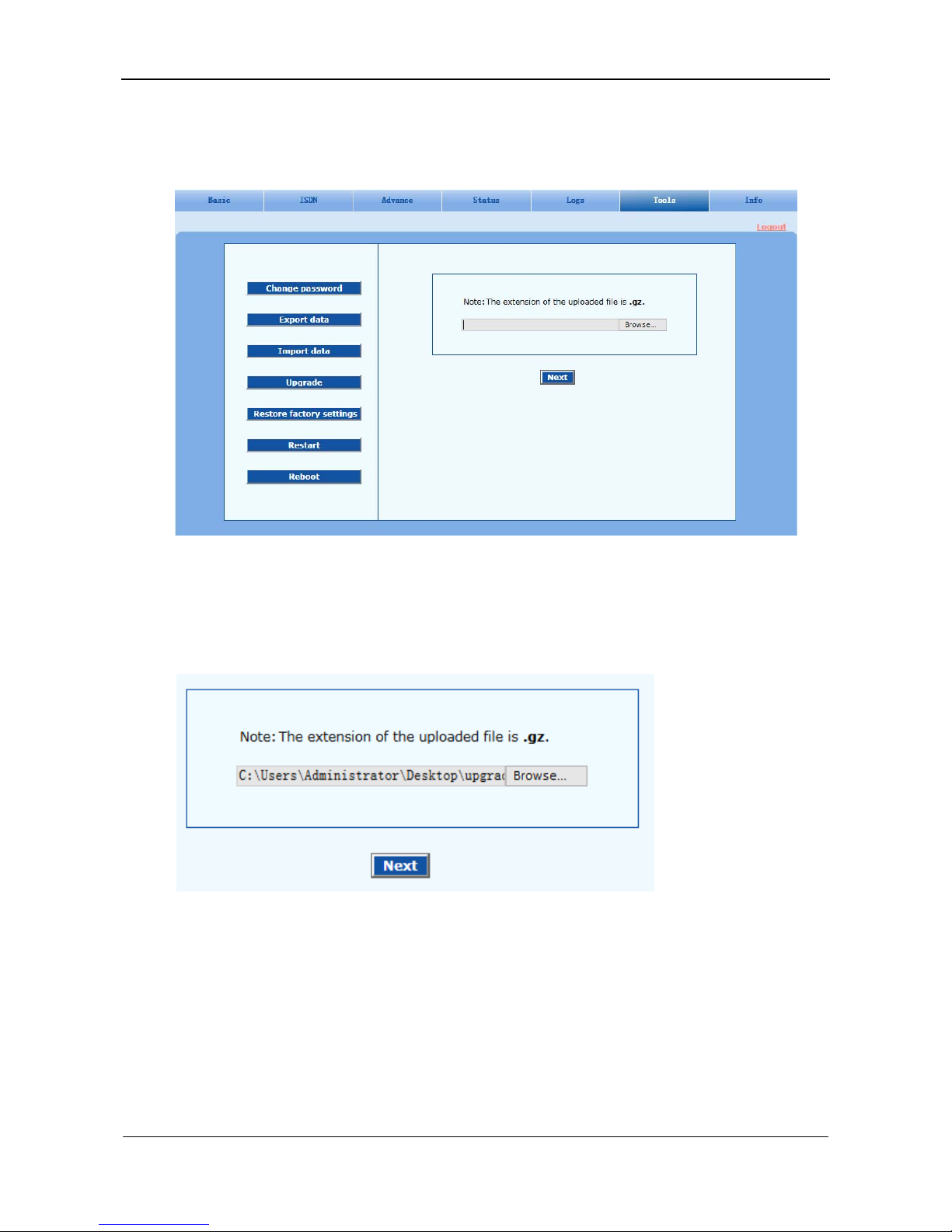
MX100E SIP-ISDN Gateway Series User Manual
www.newrocktech.com 5-35
Step1 Obtain the upgrade files (tar.gz file), and save the file onto a local computer.
Step2 Click Tools > Upgrade to access to the page of software upgrade.
Figure 5-30 Interface of Upgrade
Step3 Click Browse to select the upgrade files.
Step4 Click Next when the following interface appears, and start uploading the upgrade files to the
gateway.
Figure 5-31 File Upload Interface
Step5 Uploading will be completed in about 30 seconds, and click Upgrade on following dialog.
Page 56
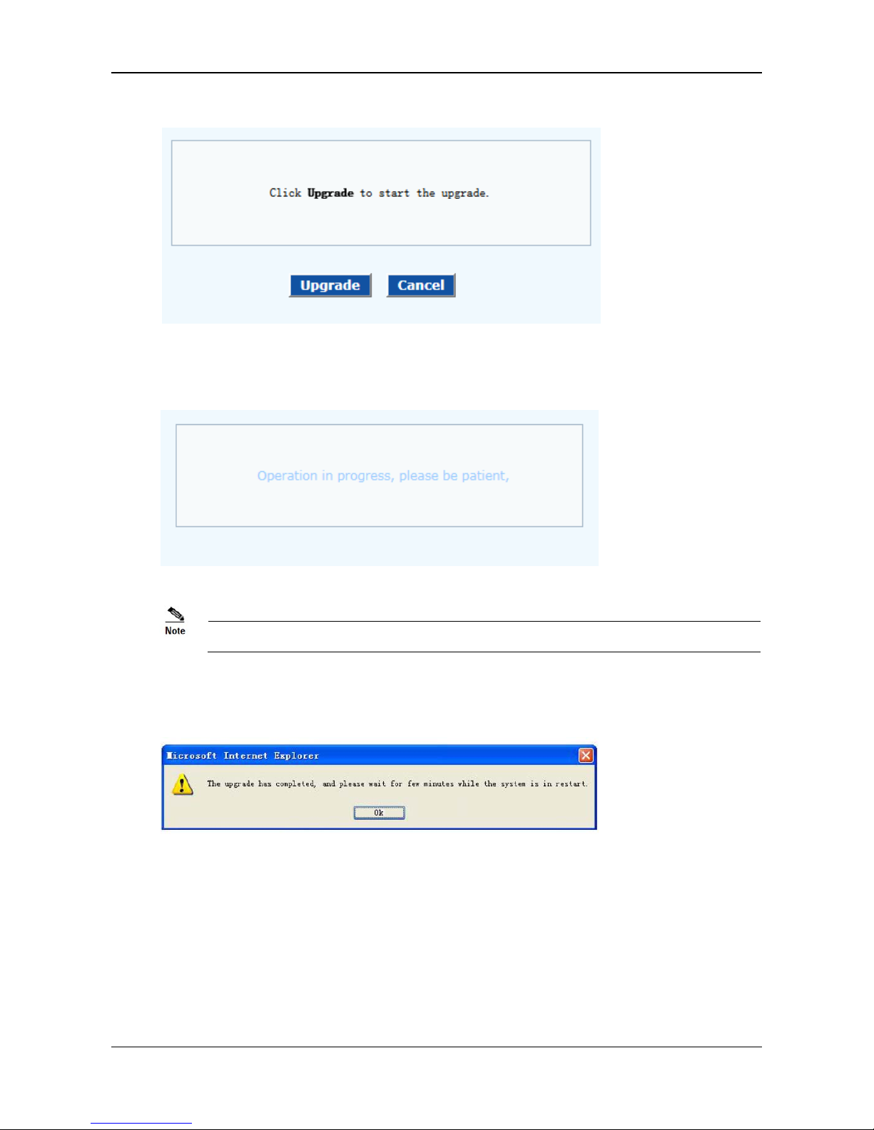
User Manual MX100E SIP-ISDN Gateway Series
5-36 www.newrocktech.com
Figure 5-32 Upgrade Interface
Step6 The following prompt appears during the upgrade.
Figure 5-33 Prompt of Upgrade Process
A few minutes are needed to upgrade the gateway. Don’t operate the gateway during this period.
Step7 After success in upgrade, the following dialog will appear, click OK.
Figure 5-34 Interface of Successful Upgrade
Step8 The gateway will reboot, and the interface will be disappeared.
Step9 Wait for about 2 minutes, and access to the interface of gateway management system, click Info
and check the software version.
5.7.5 Restore Factory Settings
After login, click Tools > Restore factory settings to restore the parameters of gateway into the facto ry
settings.
The factory settings are designed based on common applications, and therefore, no need to modify
Page 57
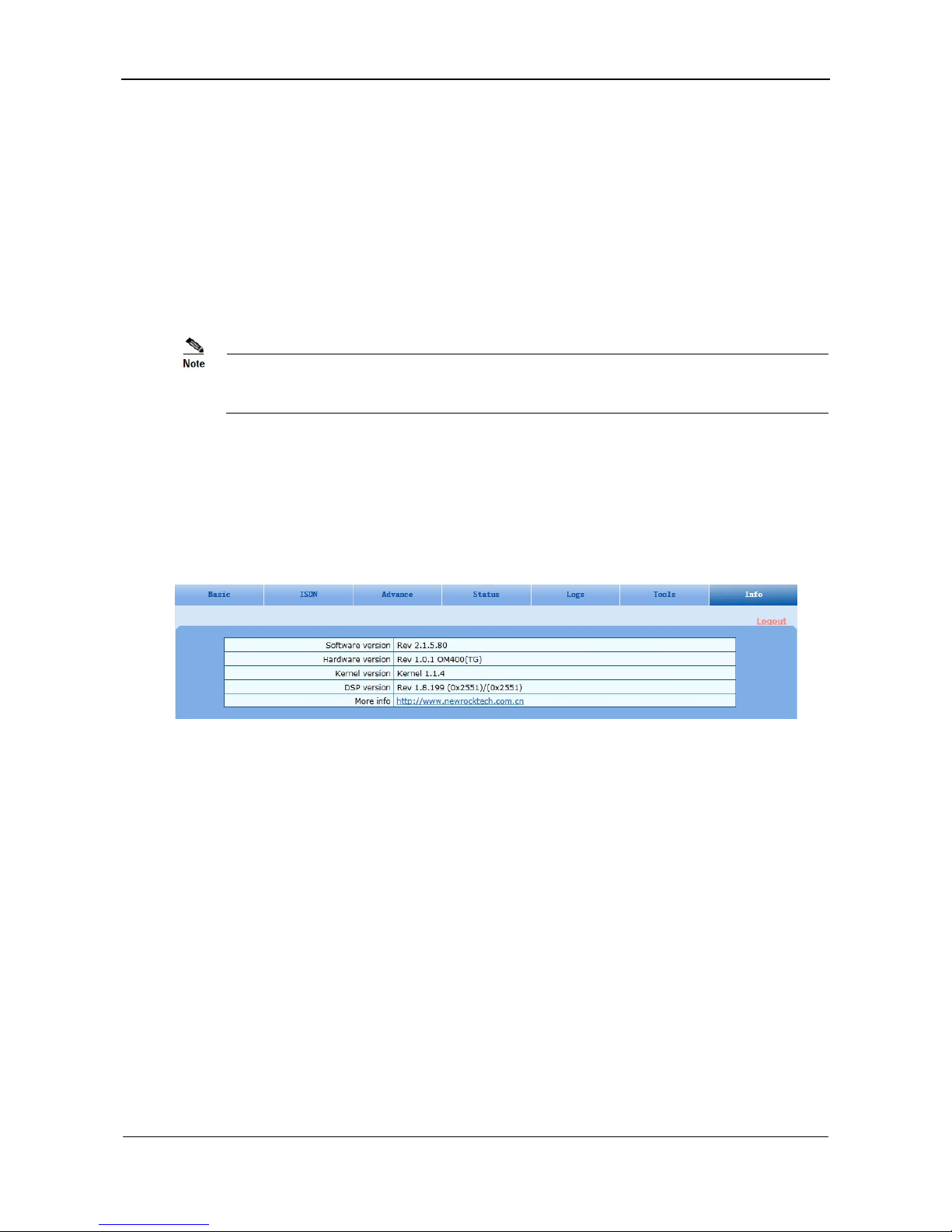
MX100E SIP-ISDN Gateway Series User Manual
www.newrocktech.com 5-37
them in many deployment situations.
5.7.6 Software Restart
After login, click Tools > Restart to restart the gateway, making modified configuration come into effect.
5.7.7 System Reboot
After login, click Tools > Reboot to restart the gateway. As this is a system wide reset, it takes longer
time.
Generally, it’s sufficient to restart software when the gateway confirms to reset; the system reboot will
be required only when network settings of the gateway are changed.
5.8 Version Information
After login, click Info to view the gateway hardware and software version information.
Figure 5-35 Version Information Interface
5.9 Logout
After login, click the Logout at top right to exit the gateway management system an d return to the login
interface.
 Loading...