

Newport Medical Instruments e360S, e360P, e360 User Manual

Newport Medical Instruments, Inc.
NEWPORT
e360 VENTILATOR
Operating Manual
For Model e360S and e360P
OPR360 WW Rev. B
05/06
NEWPORT MEDICAL INSTRUMENTS, INC.
1620 Sunflower Avenue
Costa Mesa, CA 92626 USA
Tel: 1.714.427.5811
Tel: 1.800.451.3111 (USA only)
Fax: 1.714.427.0489
Customer Service ext. 282
www.Ventilators.com
email: Info@ventilators.com
0050


Section 1 ........................................INTRODUCTION
Section 2 ........................VENTILATOR OVERVIEW
Section 3 ..........................VENTILATOR ASSEMBLY
Section 4 ........................VENTILATOR OPERATION
Section 5 ..........................STARTING VENTILATION
Section 6 ......................................................ALARMS
Section 7 ..............CLEANING and MAINTENANCE
Section 8 ......................................SPECIFICATIONS
Section 9..............EXPLANATION OF MODES AND
SPECIAL FUNCTIONS
Section 10 ......................................SAFETY CHECK
PROCEDURE
OPR360-WW B0506


TABLE OF CONTENTS
Section 1 . . . . . . . . . . INTRODUCTION
• Intended Use
• Warranty and Responsibility
• Typing Conventions
• Warnings, Cautions, and Notes
• General Cautions
• General Warnings
• Copyright Information
• Contact Information
Section 2 . . . . . . . . . . VENTILATOR OVERVIEW
• e360 Control Panel
• Graphical User Interface Display
• Patient Connections Panel
• Rear Panel
• Breath Types and Modes
• Ventilation Controls
– Control Panel
– Graphical User Interface (GUI)
• Extended Functions
• Advanced Settings
• Alarms Management
– Alarm Silence and Reset
– 360º Alarm Lamp
– Alarms & Messages display bar
– Alarms Screen button
– Alarms Setting Screen (on GUI))
• Monitored Patient Data
– Pressure Bar Graph
– Data Sets (on GUI)
– Main Screen
– Numerics
• Power Indicators
– Mains
– Int. Battery
– Device Alert
• GUI Misc. Indicators
– Patient Selection
– Breath Type & Mode Selection
– Trigger Indicator
– Alarms and Messages Display
– Internal Battery Charge Level
– Date/Time
– Hour Meter
OPR360-WW B0506

• Setup and Calibration (on GUI)
– Circuit Check
– Sensors
– Patient Setup
– Technical Setup
Section 3 . . . . . . . . . . VENTILATOR ASSEMBLY
• Unpack the Ventilator
• Mount e360 to Cart
• Check Exhalation Valve and Flow Sensor
• Connect Air and Oxygen to the Ventilator
• Connect to AC Power
• Install the Support Arm
• Assemble Patient Breathing Circuit
Section 4 . . . . . . . . . . VENTILATOR OPERATION
• Operating Principles
• Turning the Ventilator On
– Power Switch
– Standby Condition
• Setup and Calibration
– Circuit Check
– Sensors
– Patient Setup
– Technical Setup
• Preparing to Start Ventilation
– Standby Condition
– Patient Category
– Adjusting Ventilator Settings on the Control Panel
– Selecting Breath Type / Mode
– Choosing Ventilation Parameters
• Trigger
• Flow and Insp Time
• Non Invasive Ventilation (NIV)
• Adjusting Ventilator Settings on the Graphical User Interface
(GUI)
– Advanced Data Set
– Extended Functions
• Insp/Exp Hold
• Event History
• Using Other Ventilator Controls
– Manual Inflation Button
– O
2
(3 min) Button
– Accept Button
– Alarm Reset
– Alarm Silence
– Suction Disconnect Function
OPR360-WW B0506

• Managing Alarms
• Viewing Monitored Data
– Pressure Bar Graph
– Graphical User Interface (GUI)
• Using the Waves and Loops Display
– Waves & Loops
– Trends
– Scale
– Freeze
– Save & Download
Section 5 . . . . . . . . . STARTING VENTILATION
• Preparing for Patient Ventilation
– Volume Control Breath Type
– Pressure Control Breath Type
– * Volume Target Pressure Control/Volume Target
Pressure Support
* Available on e360 Plus model
Section 6 . . . . . . . . . . ALARMS
• The Alarm Silence Button
• The Alarm Reset Button
• Alarm Indicators
– 360º Alarm Lamp
– Alarms & Messages Bar Display
– Device Alert LED
• Adjustable Alarms
• Non-Adjustable Alarms
• Alarm, Violation and Remedy Guide
Section 7 . . . . . . . . . . CLEANING and MAINTENANCE
• Introduction
• Cleaning and Sterilization
• General Guidelines
– Cleaning
– Sterilization
• Maintenance Interval Summary
• Maintenance Procedures
– Rear Panel Fan Filter
– Reusable Patient Breathing Circuit
– Ventilator Exterior Cleaning
– Inspiratory Manifold
– Exhalation Valve
– Exhalation Flow Sensor
OPR360-WW B0506

– Oxygen Sensor
– Internal Battery
– Fuses
• Storing the Ventilator
• Repackaging the Ventilator
Section 8 . . . . . . . . . . SPECIFICATIONS
• Control Panel Functions and Controls
• Graphical User Interface Functions and Controls
– Main Screen
– Extended Functions
– Advanced Settings
• Setup and Calibration Controls
– Patient Setup
– Circuit Check
– Sensors
– Technical Setup
• Monitored Data
– Graphical User Interface
• Scales Specifications
• Alarms
– Adjustable
– Non-adjustable
– Alarm Features
– Informational Messages
• Physical Specifications
Section 9 . . . . . . . . . . EXPLANATION OF MODES AND SPECIAL FUNCTIONS
• Breath Types
– Volume Control
– Pressure Control
– * Volume Target Pressure Control
• Ventilation Modes
– A/CMV
– SIMV
– SPONT
• Spontaneous Breath Management in SIMV and SPONT
Modes
– Pressure Support
– * Volume Target Pressure Support
• Advanced Features and Special Functions
– Slope/Rise
– Expiratory Threshold
– Leak Compensation
– Compliance Compensation
OPR360-WW B0506

– Non Invasive Ventilation
– * Open Exhalation Valve
* Available on e360 Plus model
Section 10 . . . . . . . . . SAFETY CHECK PROCEDURE
• Set Up and Inspection
• Emergency Intake Valve
• Circuit Check
• Gas Supply Alarms
• AC Power Loss/Battery Backup Alarm
• High/ Low Airway Pressure Alarms, Disconnect and Alarm
Silence
• Minute Volume, Back Up Ventilation and Apnea Alarms
• Trigger/Pressure Support
• Volume/Flow/Rate Accuracy
• Shut Down Alarm
• e360 Safety Check Record
OPR360-WW B0506


1. INTRODUCTION
Intended Use ........................................................ 1-1
Warranty and Responsibility ................................ 1-1
Typing Conventions .............................................. 1-3
Warnings, Cautions and Notes ............................ 1-3
General Cautions .................................................. 1-4
General Warnings.................................................. 1-4
Copyright Information .......................................... 1-6
Contact Information .............................................. 1-6
OPR360-WW B0506

INTENDED USE
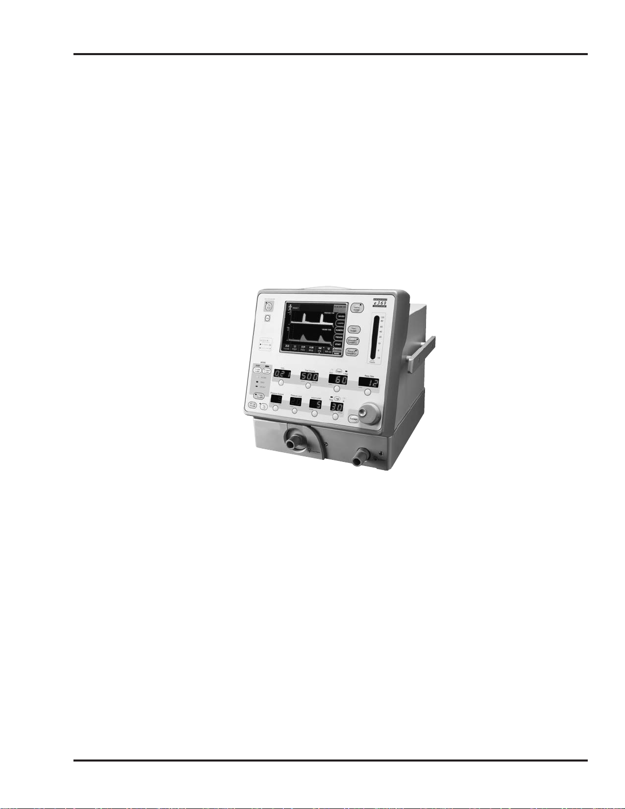
The e360 Ventilator System is intended to provide continuous
(endotracheal or tracheostomy [ET] tube) or non-continuous
(mask) ventilatory support and monitoring for infant, pediatric, and
adult patients requiring tidal volumes equal to or greater than 20
milliliters (mL). The device is for use by prescription only. The
intended environments include hospital, hospital-type, and intrahospital transport environments. Hospital use typically includes
general care floors, operating rooms, special procedure areas,
emergency rooms, and intensive and critical care areas within the
hospital. Hospital-type use includes facilities such as or similar to
surgicenters, sub-acute centers, and special nursing facilities
outside of the hospital. Intra-hospital transport includes patient
transport within the hospital or hospital-type facility.
WARRANTY AND RESPONSIBILITY
WARRANTY
The Newport e360 Ventilator System is guaranteed to be free of
defects for a period of one (1) year from date of delivery. The
following are exceptions to this warranty:
• Defects caused by misuse, mishandling, tampering, or by
modifications not authorized by Newport or its representatives
are not covered.
• Rubber and plastic components and materials are warranted
to be free of defects at time of delivery.
Figure 1-1.
e360 Ventilator System
SECTION 1
OPR360-WW B0506 1-1

• The O2sensor is covered for a period of one year from
purchase date.
Any product, which proves to be defective in workmanship or
material will be replaced, credited, or repaired with Newport
holding the option. Newport is not responsible for deterioration,
wear, or abuse. In all cases, Newport will not be liable beyond the
original selling price.
Federal Law in the United States requires traceability of this
equipment. Please fill out the self-addressed Warranty
Registration Card included with the product and return it to
Newport promptly.
Application of this warranty is subject to the following conditions:
• Newport or its authorized representatives must be promptly
notified upon detection of the defective material or equipment.
• Defective material or equipment must be returned to Newport
or its authorized representative.
• Examination by Newport or its authorized representatives
must confirm that the defect is covered by the terms of this
warranty.
In order to assure complete protection under this warranty, the
Warranty Registration Card must be returned to Newport within
ten (10) days of receipt of equipment.
The above is the sole warranty provided by Newport. No other
warranty expressed or implied is intended. Representatives of
Newport are not authorized to modify the terms of this warranty.
RESPONSIBILITY FOR PATIENT SAFETY
To use this product correctly and effectively and to avoid
hazards, carefully read and observe all sections of this
manual prior to use.
Because the design, operating manual, and labeling of the e360
Ventilator System assume that its sale and use are restricted to
qualified, trained professionals under the direction of a physician
who understand the general operating characteristics of
ventilators, this manual includes instructions, warnings, and
cautions that are specific to the design of this ventilator. This
manual excludes references to hazards that are obvious to
medical professionals, the consequences of product misuse, or to
potentially adverse effects in patients with abnormal conditions.
INTRODUCTION
1-2 OPR360-WW B0506

Product modification or misuse can be dangerous. Newport
disclaims all liability for the consequences of product alterations
or modifications, as well as for the consequences that might
result from the combination of this ventilator with other products,
whether supplied by Newport or by other manufacturers, if such a
combination is not endorsed by Newport.
Federal Law and Regulations in the United States and Canada
restrict this device to sale by or on the order of a physician.
It is the responsibility of the ventilator operator to choose
appropriate monitoring of equipment performance and patient
condition. Electronic surveillance of equipment performance and
patient condition cannot take the place of directly observing
clinical signs. The ventilator operator is solely responsible for
selecting the optimum level of patient monitoring.
LIMITATION OF LIABILITY
The liability of Newport, whether arising out of, or related to
manufacture and sale of the goods, their installation,
demonstration, sales representation, use, performance, or
otherwise, including any liability based upon Newport’s product
warranty, is subject to and limited to the exclusive terms and
conditions as set forth, whether based upon breach of warranty or
any other cause of action whatsoever, regardless of any fault
attributable to Newport and regardless of the form of action
(including, without limitation, breach of warranty, negligence, strict
liability, or otherwise).
The stated expressed warranties are in lieu of all other warranties,
expressed or implied, including, without limitation, warranties of
merchantability, fitness for any purpose, or noninfringement.
Newport shall not be liable for, nor shall the buyer be entitled to
recover, any special incidental or consequential damages or any
liability incurred by buyer to any third party in any way arising out
of or relating to the goods.
TYPING CONVENTIONS
Controls, buttons, and alarms are shown in this manual as
italicized text, written as they appear on the ventilator (for
example, SPONT for spontaneous mode).
WARNINGS, CAUTIONS, AND NOTES
Please review all WARNINGS and CAUTIONS outlined in this
manual before operating the ventilator.
SECTION 1
OPR360-WW B0506 1-3

Strictly follow this Operating Manual. Any use of the product
requires full understanding and strict observation of all sections of
these instructions. The equipment is only to be used for the
purpose specified under INTENDED USE and in conjunction with
appropriate patient observation and monitoring. Observe all
WARNINGS and CAUTIONS that appear in this manual and on
equipment labels.
WARNING A warning describes a condition that can cause
personal injury.
Caution A caution describes a condition that can cause
damage to equipment.
NOTE: A note emphasizes information that is important or
convenient.
GENERAL CAUTIONS
• Use only dry clean compressed air and medical grade oxygen.
• Use only fuses with the correct rating.
• Do not place liquids on or near the ventilator.
GENERAL WARNINGS
• Danger: there is a risk of explosion if used in the presence of
flammable anesthetics.
• All ventilator controls and alarm limits must be appropriate for
the patient’s condition, according to the therapy prescribed by
a physician.
• Newport cannot warrant or endorse the safe performance of
third party humidifiers for use with the e360 Ventilator.
• Contact the manufacturers/distributors of third party
humidifiers about the compliance and performance
characteristics of their products.
•A patient connected to a ventilator requires the constant
attention of medical staff to the patient’s condition, and to any
significant difference between monitored and set values that
may indicate a fault in ventilator operation.
• Before and during the use of the e360 Ventilator, make sure
that all connections in the patient circuit are secure. Ensure
the integrity of each part of the patient circuit, humidifier
connections, and humidifier chamber.
• Always use appropriate monitors to ensure sufficient
oxygenation and ventilation (such as a pulse oximeter and
capnograph) when the e360 Ventilator is in use on a patient.
INTRODUCTION
1-4 OPR360-WW B0506

• Have an alternate method of ventilation available for use when
using the e360 Ventilator. If the ventilator’s operation or
monitoring functions are in doubt, discontinue ventilator use
and employ an alternate method of ventilation.
• Have an alternate method of oxygen monitoring with high and
low alarms available for use when using the e360, in the event
the built-in oxygen monitor is unavailable due to a defective or
missing oxygen sensor.
• Use a bacteria filter between the inspiratory (TO PATIENT) port
and the inspiratory limb of the breathing circuit to prevent
contaminants in the patient exhaled gas from entering the
inspiratory manifold when the emergency relief valve opens
(when there is a Device Alert, Both Air/O
2
Supply Loss, or
Sustained High Baseline Pressure Alarm). If a filter is not used,
the inspiratory manifold will have to be cleaned and sterilized
between patients.
• Use of a bacteria filter between the expiratory limb of the
breathing circuit and the e360 Ventilator to prevent
contaminants in the exhaled gas from entering the exhalation
system is recommended. If a filter is not used, the exhalation
valve will have to be cleaned and sterilized and the flow
sensor will have to be replaced between patients.
• Use an additional single patient use bacteria filter between the
expiratory limb of the breathing circuit and the primary
expiratory bacterial filter when nebulized medications are
delivered through the breathing circuit. Failure to do so could
lead to expiratory volume monitoring inaccuracies, damage to
the expiratory flow sensor, increased resistance to patient
exhalation and even exhalation system obstruction. Discard
the filter at the completion of nebulized drug delivery or more
frequently as needed to minimize expiratory resistance. Follow
filter manufacturer’s instructions.
NOTE: Install bacteria filters, water traps and/or heated wires as
required. Newport recommends the use of a bacteria filter on both
the inspiratory and expiratory limbs of the breathing circuit to
speed ventilator turnover and protect ventilator components.
This equipment has been tested and found to comply with the
EMC limits for the Medical Device Directive 93/42/EEC (EN 55011
Class 1 and EN 60601-1-2). These limits are designed to provide
reasonable protection against harmful interference in a typical
medical installation. The equipment generates, uses, and can
radiate radio frequency energy and, if not installed and used in
accordance with these instructions, may cause harmful
interference to other devices in the vicinity. However, there is no
guarantee that interference will not occur in a particular
SECTION 1
OPR360-WW B0506 1-5

installation. If this equipment does cause harmful interference with
other devices, which can be determined by turning the equipment
off and on, the user is encouraged to try to correct the
interference by one or more of the following measures:
• Reorient or relocate the receiving device.
• Increase the separation between the equipment.
• Connect the equipment into an outlet on a circuit different
from that to which the other device(s) is connected.
• Consult the manufacturer or field service technician for help.
Accessory equipment connected to the analog and digital
interfaces must be certified according to the respective IEC
standards (e.g. IEC 60950 for data processing equipment and IEC
60601 for medical equipment). Furthermore, all configurations shall
comply with the system standard IEC 60601-1-1. Any person who
connects additional equipment to the signal input or output parts
“configures” a medical system, and is therefore responsible for
ensuring that the system complies with the requirements of the
system standard IEC 60601-1-1. If in doubt, consult the Technical
Service department or your local representative.
Dispose of waste products, residue, etc., in accordance with the
appropriate national requirements.
COPYRIGHT INFORMATION
Copyright 2006 Newport Medical Instruments, Inc. All rights
reserved. The Newport e360 Ventilator system is manufactured in
accordance with Newport Medical Instruments, Inc. proprietary
information.
The information in this manual is the sole property of Newport
Medical Instruments, Inc. and may not be duplicated without
permission. This manual may be revised or replaced by Newport
Medical Instruments, Inc. at any time and without notice.
CONTACT INFORMATION
For more information about parts or ordering, contact Newport
Customer Service:
Telephone (voice mail): 714.427.5811 Extension: 282
Fax: 714.427.0489
Email: Customers@NewportNMI.com
Internet: www.NewportNMI.com or www.ventilators.com
Customer Service Hours: Monday through Friday,
8:00 am to 5:00 pm (USA Pacific Standard Time)
Shipping Address: Attn: Receiving Dept.
1620 Sunflower Avenue, Costa Mesa, CA 92626 USA
INTRODUCTION
1-6 OPR360-WW B0506

EU Representative:
Newport Medical Instruments, Inc.
Att: Robert Brink
c/o Braun & Co.
19 Pasture Rd.
Barton-on-Humber, North Lincolnshire
DN18 5HN, England
Tel:44.7768.231311
Fax:44.1652.633399
SECTION 1
OPR360-WW B0506 1-7


2. VENTILATOR OVERVIEW
e360 Control Panel................................................ 2-1
Graphical User Interface Display .......................... 2-2
Patient Connections Panel .................................. 2-3
Rear Panel ............................................................ 2-4
Breath Types and Modes .................................... 2-5
Ventilation Controls
Control Panel .................................................. 2-6
Graphical User Interface .................................. 2-7
Extended Functions
Advanced Settings
Alarms Management ............................................ 2-7
Alarm Silence and Reset
360º Alarm Lamp
Alarms & Messages display bar
Alarms Screen button
Alarms Setting Screen (on GUI)
Monitored Patient Data ........................................ 2-9
Pressure Bar Graph
Data Sets (on Graphical User Interface)
Main Screen – Waves, Loops & Trends display
Numerics
Power Indicators ..................................................2-10
Mains
Int battery
Device Alert
GUI Misc. Indicators ............................................2-10
Patient Selection
Breath Type & Mode Selection
Trigger Indicator
Alarms and Messages Display
OPR360-WW B0506

Internal Battery Charge Level
Date/Time
Hour Meter
Setup and Calibration (on GUI) ............................2-11
Circuit Check
Sensors
Patient Setup
Technical Setup
OPR360-WW B0506
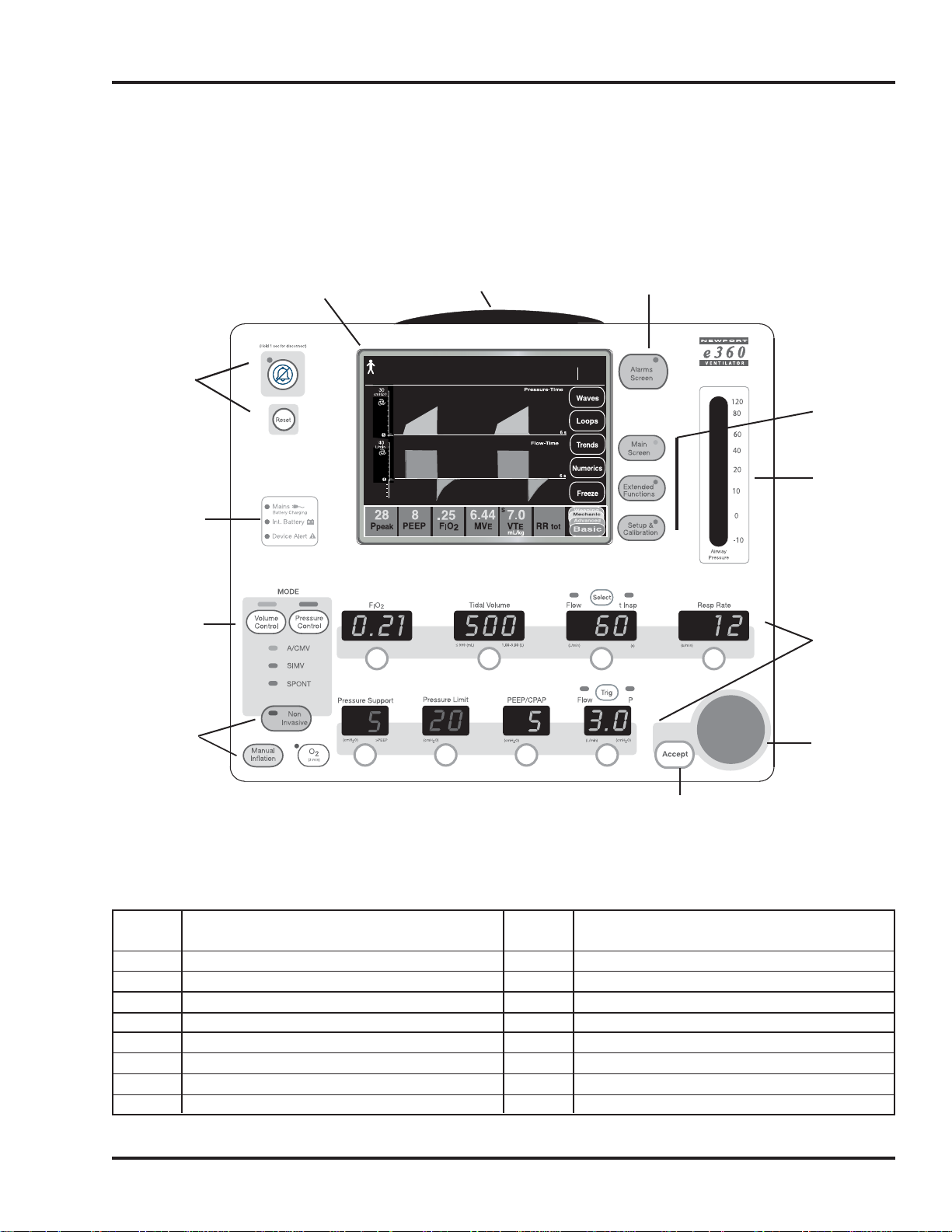
e360 Control Panel
The e360 Control Panel is clearly labeled with standard ventilation
terminology, following ISO standards. Figure 2-1 shows the e360
Control Panel and the following table provides descriptions of
each area.
SECTION 2
OPR360-WW B0506 2-1
No. Description
1. Alarm Silence and Reset Buttons
2. Graphical User Interface (GUI)
3. 360º Alarm Lamp
4. Alarms Screen Menu Button
5.
Graphical User Interface Menu Buttons
6. Pressure Bar Graph
7. Ventilation Controls
No. Description
8. Adjustment Knob
9. Accept Button
10. Special Functions
Non Invasive Button
Manual Inflation Button
O
2
(3 min) Button
11. Modes/Breath Types Button
12. Power Indicators
Figure 2-1. e360 Control Panel
1.
12.
11.
10.
2. 3.
ADULT
PC-SPONT
05-01-2006 15:30
18
4.
Hours
Int
999999.7
Bat
5.
6.
7.
8.
9.
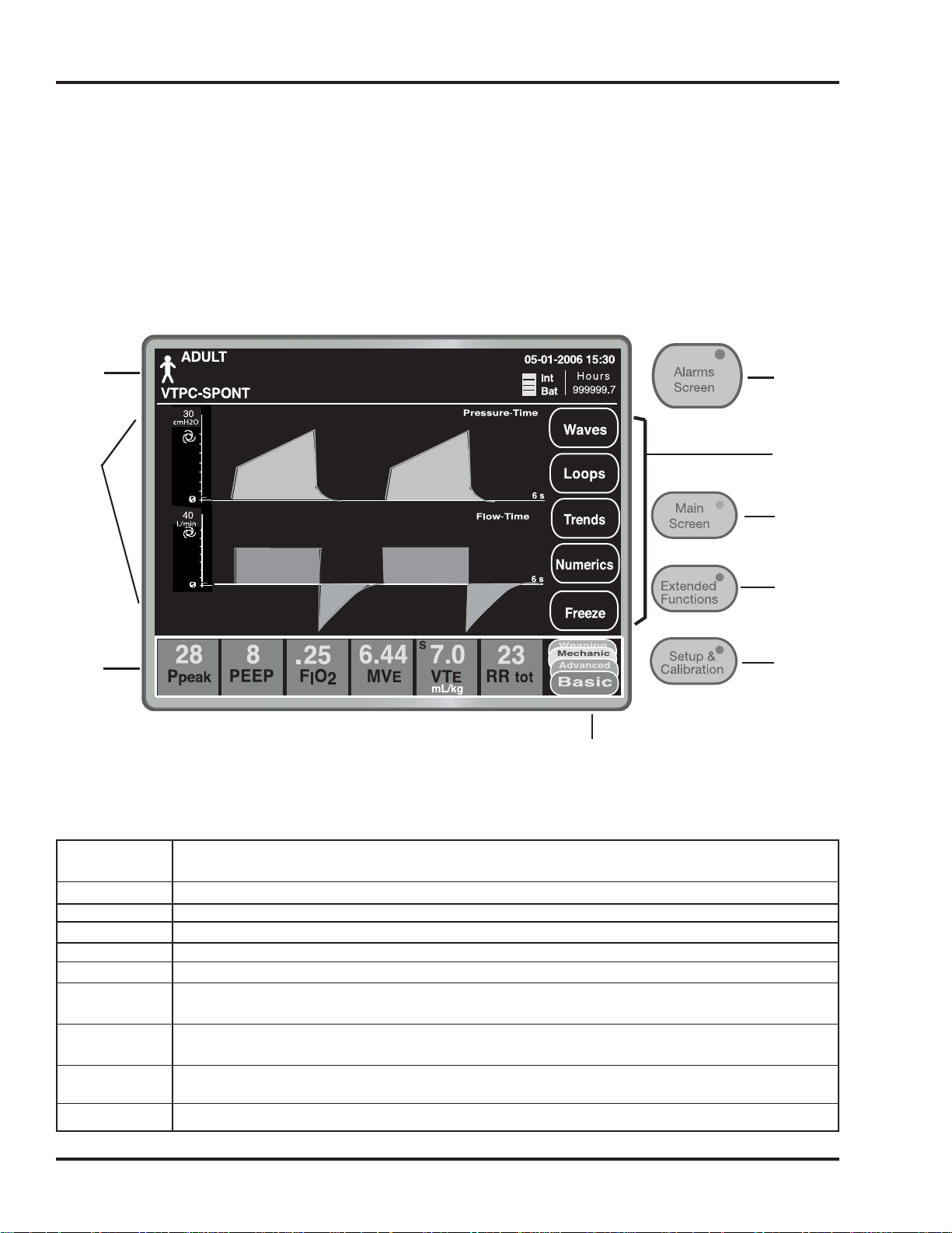
Graphical User Interface Display (GUI)
The e360 Graphical User Interface allows the user to quickly
navigate through a number of screens to access extensive data
including monitoring, custom set-up, automated calibrations,
numerics, wave forms and loops. Figue 2-2 shows the e360 GUI
main screen and the following table provides a description of
each area.
VENTILATOR OVERVIEW
2-2 OPR360-WW B0506
Item No. Description
1. GUI Status Bar
2. Main Display Area
3. Data Sets Bar (4 data sets display monitored data & Advanced Settings)
4. Alarms Screen Menu Button (press to access Alarms settings touch screen)
5. GUI Menu Touch Buttons
6. Main Screen Menu Button (press to access Waves, Loops, Trends &
Numerics touch screen)
7. Extended Functions Menu Button (press to access Extended Functions
touch screen)
8. Setup & Calibration Menu Button (press to access Circuit Check, Sensors
(calibration) Patient Setup, and Technical Setup touch screen)
9. Data Set Touch Button
Figure 2-2. e360 GUI
1.
2.
3.
4.
5.
6.
7.
8.
9.
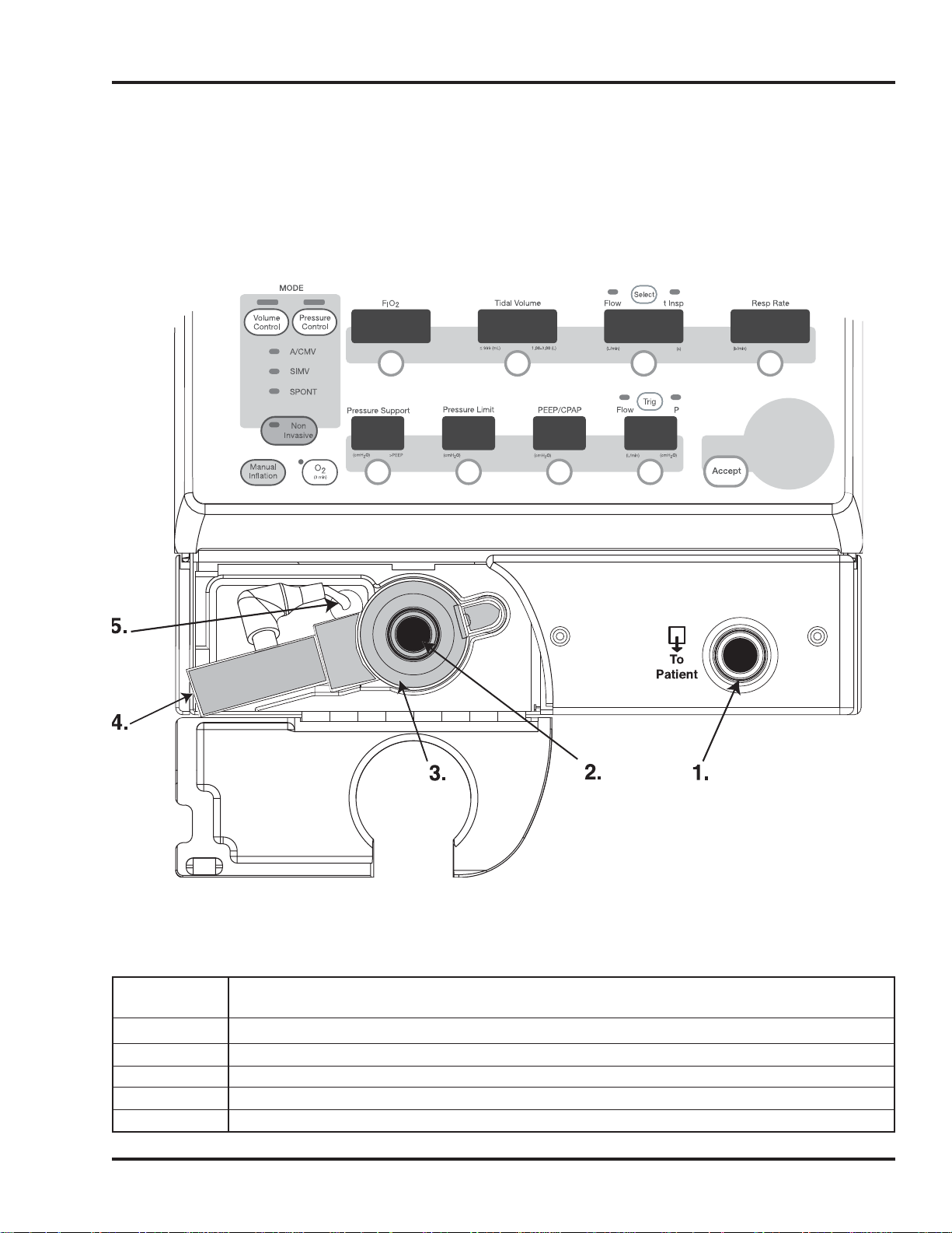
Patient Connections Panel
The lower panel area on the front of the e360 contains patient
connection ports and provides easy access to the exhalation
valve and flow sensor. Figure 2-3 shows the Patient Connections
Panel and the following table describes each connector.
SECTION 2
OPR360-WW B0506 2-3
Item No. Description
1. Inspiratory Port (To Patient) 22 mm OD
2. Expiratory Port (From Patient) 22 mm OD
3. Exhalation Valve
4. Exhalation Flow Sensor
5. Flow Sensor Cable connection
Figure 2-3. e360 Patient Connection Panel
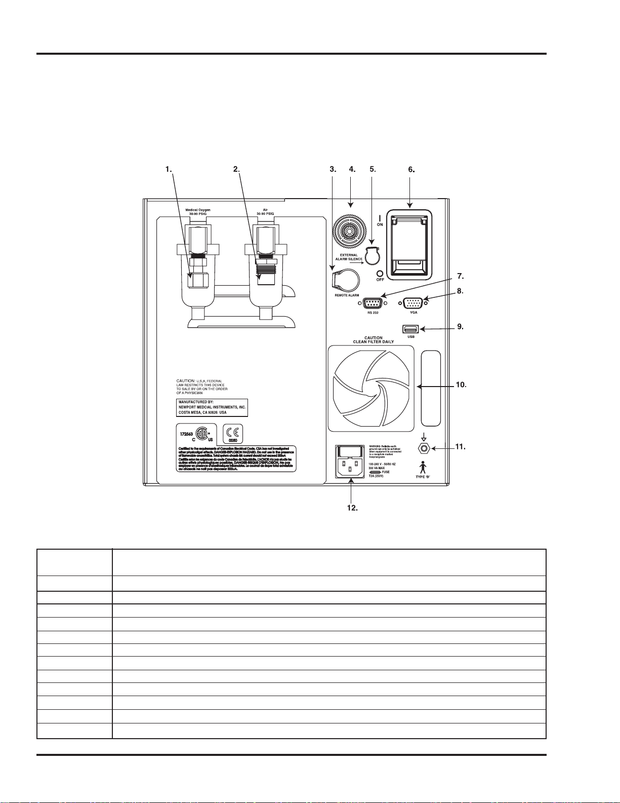
Rear Panel
The e360 rear panel contains the on/off power switch and other
connectors to provide access to various external devices. Figure
2-4 shows the e360 rear panel and the following table provides a
description of each area.
VENTILATOR OVERVIEW
2-4 OPR360-WW B0506
Item No. Description
1. Oxygen Inlet
2. Air Inlet
3. Remote Alarm connection
4. Alarm speaker
5. External Alarm Silence connection
6. On/ Off power switch
7. RS232 connection
8. VGA connection
9. USB connection
10. Cooling Fan Filter housing
11. Equipotential grounding stud
12. AC power connection
Figure 2-4. e360 Rear Panel
Serial # XXXXXX
Newport Model e360
This section provides an overview of the buttons, controls and
functions of the ventilator and where they are located. Before
using the e360 Ventilator on patients, please read and understand
all of the information in this manual.
NOTE: Ventilation controls (on the Control Panel and on the GUI)
are adjusted with the Touch-Turn-Accept method. Touch the
desired selection, Turn the Adjustment Knob to make a change
and press the Accept button to confirm or invoke the change. If
the Accept button is not pressed within 10 seconds the setting
will not be changed and will revert to the previous condition/value.
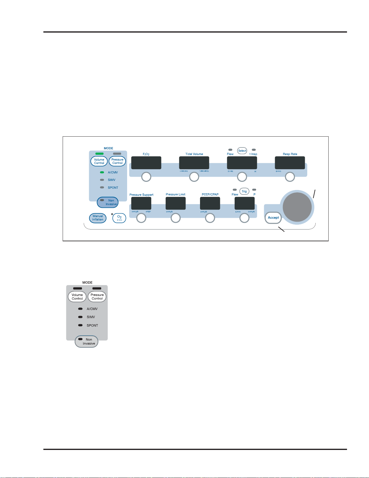
BREATH TYPE / MODE
Breath Type Selection
To select a breath type, press Volume Control or Pressure Control.
The LED will continue to flash until the Accept button is pressed
or 10 seconds has passed. If Accept is not pressed within 10
seconds the setting will not be changed and will revert to the
previous condition/value.
Mode Selection
To select a mode, press the selected breath type button, Volume
Control or Pressure Control, repeatedly until the desired mode
indicator is flashing. Press Accept to invoke the change.
NOTE: On the e360 Plus model: To select a Volume Target
Pressure Control breath type, Select Pressure Control breath type
and then access the Advanced Data Set on the GUI. Press the
Volume Target touch button and use the Adjustment knob to
select On. Press Accept button to confirm. (See “Advanced
Settings”).
SECTION 2
OPR360-WW B0506 2-5
Adjustment Knob
Accept Button
0.21 500 60 1 2
5
20
5
3.0
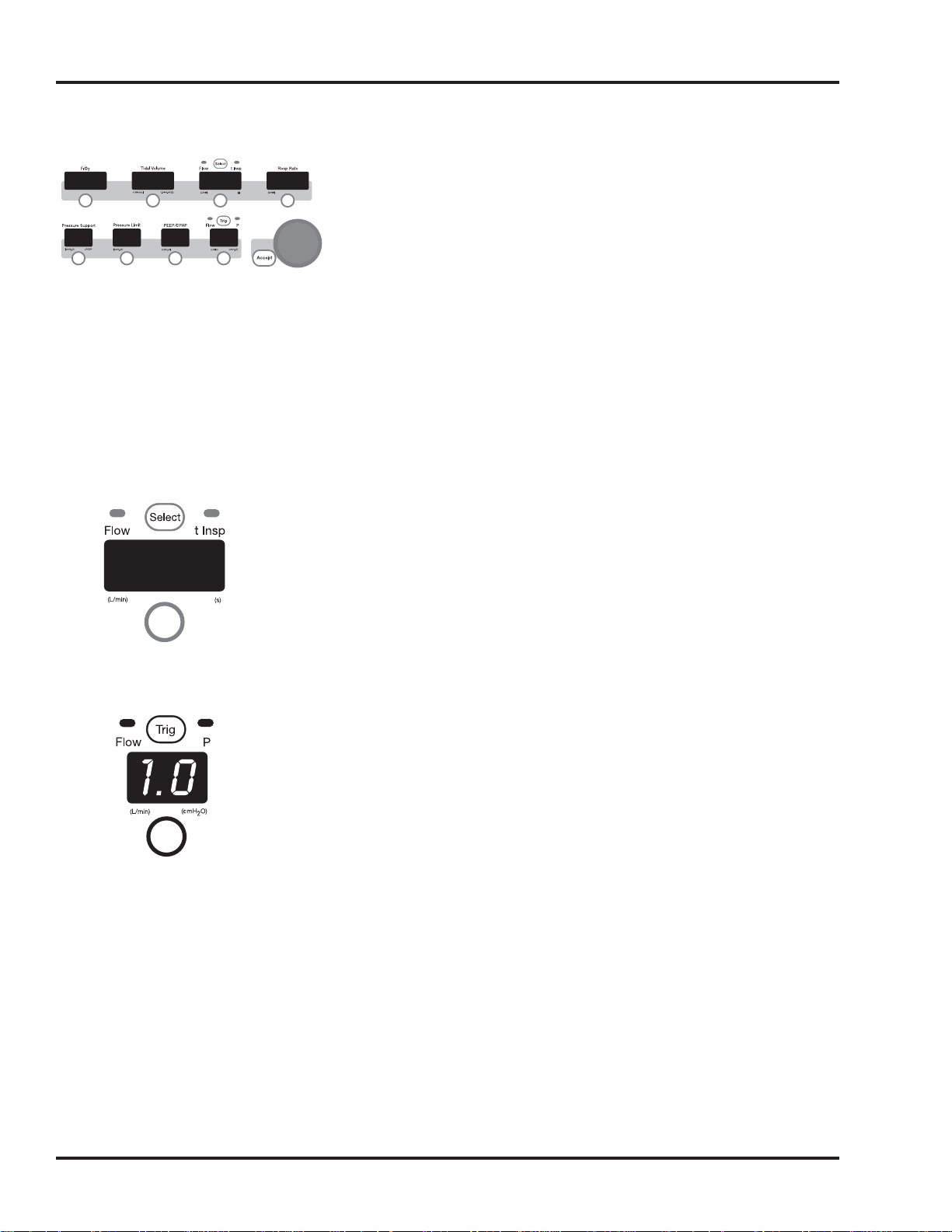
VENTILATION CONTROLS / CONTROL PANEL
FIO2, Tidal Volume, Flow, Inspiratory Time (t Insp), Respiratory
Rate (Resp Rate), Pressure Support, Pressure Limit, PEEP/CPAP
and Trigger (flow or pressure) can be set via the membrane
buttons on the Control Panel.
Press the button below the corresponding display to select
parameter. The display will flash. Rotate the Adjustment Knob to
adjust setting. Press the Accept button to invoke the change. The
display will stop flashing and the setting will take effect.
Before pressing the Accept button to invoke the new change, the
user can select and adjust multiple other controls in the same
area and then press the Accept button, thereby accepting all of
the changes.
In Volume Control, you can choose to set either Flow or
Inspiratory Time (see t insp) for mandatory breaths.
Press the “Select” button above the display to toggle between
Flow and t Insp. An LED above the display will indicate the
current selection.
To change the Flow or t Insp setting: Press the button below the
control display and use the Touch-Turn-Accept method.
To change the trigger sensitivity type: Press the Trig button at the
top of the display to toggle between Trigger Flow or Pressure (P)
trigger. An LED above the display will indicate the current
selection.
To change the trigger setting: Press the button below the control
display and use the Touch-Turn-Accept method.
VENTILATOR OVERVIEW
2-6 OPR360-WW B0506
60
0.21 500 60
20
5
3.0
5
12
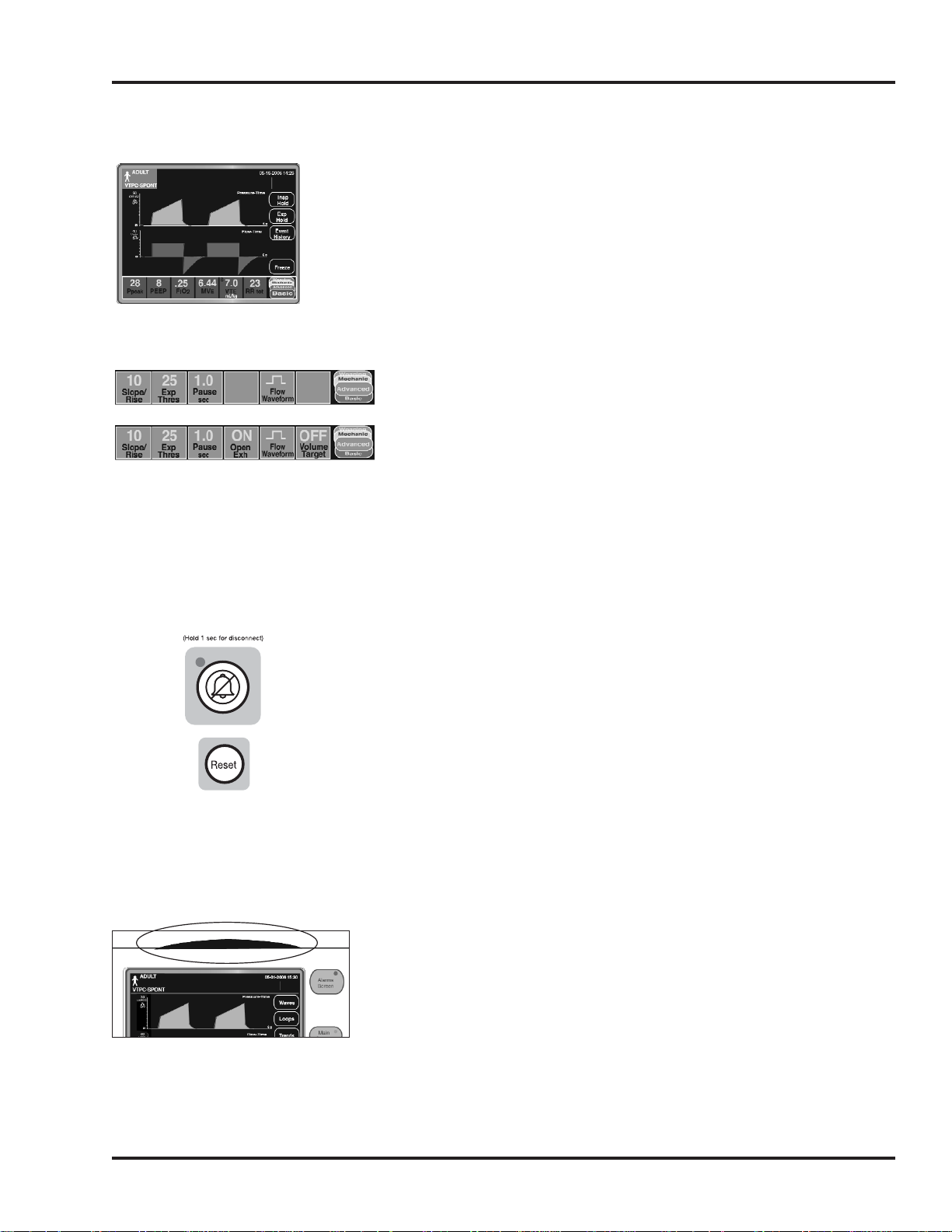
VENTILATION CONTROLS – GRAPHICAL USER INTERFACE (GUI)
Extended Functions
Pressing the Extended Functions menu button on the control
panel reveals new GUI menu buttons: Insp Hold, Exp Hold, Event
History and Freeze. Touch and hold Insp or Exp Hold to start the
maneuver for the current or following breath (the Accept button is
not needed). Touch the Event History button to access the Event
History log that records up to 1000 events.
Advanced Settings
Additional ventilation controls can be found on the Graphical User
Interface. Touch the button on the lower right hand corner of the
screen to change the lower display “Data Set Bar” to the
Advanced Data Set. Here the user can adjust and enable settings
for Slope/Rise, Expiratory Threshold, Pause, Flow Wave. If you
have the e360 Plus model, Volume Target and Open Exhalation
Valve are also adjustable. Adjust or enable/disable these settings
the same way as other ventilator controls; Touch-Turn-Accept.
ALARM MANAGEMENT
Alarm Silence / Reset
Pressing the Alarm Silence button mutes silenceable audible
alarms for 120 seconds and cancels the Shutdown alarm that
occurs after the power is switched to Off. (It does not silence
Device Alert alarms until after power is switched off.)
The LED lights while alarm silence is active. Press again to cancel
the silence. To perform Suction Disconnect Function, press and
hold Alarm Silence until two tones sound. See Section 6/Alarms
for details.
Pressing the Reset button clears all visual indicators for alarms
that are no longer violated.
360º Alarm Lamp
The 360º Alarm Lamp (located on the top center of e360 bezel)
flashes to indicate an alarm violation. It flashes Yellow for low and
medium level alarms, Red for high level alarms.
SECTION 2
OPR360-WW B0506 2-7
*e360 Plus model
*
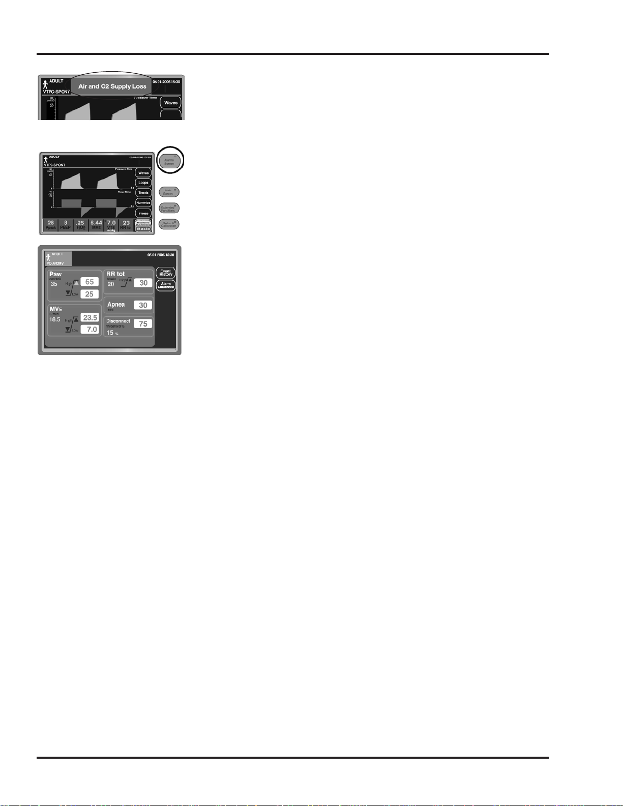
Alarms & Messages Display Bar
The Alarms & Messages bar, located at the top, center of the
Graphical User Interface status bar, shows user prompt messages
and alarm violation messages.
Alarms Screen Menu Button
Pressing the Alarms Screen menu button opens the Alarm
Settings screen on the Graphical User Interface. From this screen
the user can modify all adjustable alarm settings, view Event
History and adjust Alarm Loudness.
Alarm Settings Screen
The Alarm Settings screen allows the user to adjust high and low
Paw, high and low MVE, high Respiratory Rate (RRtot), Apnea
time and Disconnect Threshold % alarm limit settings in relation
to a monitored displayed value.
To change an alarm setting: Press the displayed value button of
the desired alarm, the number in the display will flash, rotate the
Adjustment Knob to the desired setting and press the Accept
button to invoke the change. The display will stop flashing and
the setting will take effect.
Multiple alarms can be adjusted before touching the Accept
button as long as there is not a pause of 10 seconds or more
between changes. If Accept button is not pressed, after 10
seconds all adjusted alarms will revert to their original values.
• Event History
Touching the Event History button takes you to the Event History
Log where the user can view up to 1000 of the most recent
events including alarm violations, setting changes and power
On/Off sequences.
• Alarm Loudness
To adjust the alarm tone volume, touch the Alarm Loudness
button. Use the Adjustment Knob to adjust the loudness up or
down (a lower number is quieter and a larger number is louder).
Press the Accept button to invoke the change.
To exit either of these screens, touch any menu button on the
Control Panel.
VENTILATOR OVERVIEW
2-8 OPR360-WW B0506
 Loading...