

Newport Medical Instruments e360 Service Manual

Newport Medical Instruments, Inc.
0050
NEWPORT e360 VENTILATOR
Service Manual
SER360 Rev. A
11/06
MEDICAL
NEWPOR
1620 Sunflower Avenue
Costa Mesa, CA
Tel: 714.427.5811
el: 800.451.3111 (USA only)
T
Fax: 714.427.0489
Customer Service ext. 282
www
email:
T
92626 USA
.NewportNMI.com
Info@NewportNMI.com
INSTRUMENTS, INC.


TABLE OF CONTENTS
Section 1..........................................INTRODUCTION
Section 2 ..................MAINTENANCE, OVERHAUL
& SOFTWARE UPGRADE
Section 3 ..................TROUBLESHOOTING GUIDE
Section 4 ..........................COMPONENT REMOVAL
& REPLACEMENT
Section 5 ................CALIBRATION PROCEDURES
Section 6................OPERATIONAL VERIFICATION
PROCEDURE
Section 7 ..............CLEANING and MAINTENANCE
Appendix A ....................THEORY OF OPERATION
Appendix B ......................ORDERING & CONTACT
INFORMATION
Appendix C ............................................DIAGRAMS
SER360 A1106


1. INTRODUCTION
Introduction............................................................ 1-1
Definitions.............................................................. 1-1
General Warnings.................................................. 1-1
General Cautions .................................................. 1-2
Warranty ................................................................ 1-2
Factory Service...................................................... 1-3
Copyright Information............................................ 1-3
Contact Information .............................................. 1-3
SER360 A1106


INTRODUCTION
DEFINITIONS
SECTION 1
It is very important to read and understand all of the information in
this manual before attempting to service the e360 Ventilator.
Please review all warnings and cautions in this manual before
attempting to service the e360 ventilator.
WARNING A WARNING describes a condition that can cause
personal injury.
Caution A Caution describes a condition that can cause
damage to equipment.
NOTE: A NOTE emphasizes information that is important or
convenient.
Inspection: examination of actual condition.
GENERAL WARNINGS
Service: measures to maintain specified condition.
Repair: measures to restore to specified condition.
Maintenance: inspection, service, and repair where necessary.
Preventive Maintenance: maintenance performed at regular
intervals.
Operational Verification: a routine verification procedure to
ensure proper operation.
Overhaul Procedure: a procedure for replacing key components
at regular intervals
Please review all warnings and cautions in this manual before
attempting to service the ventilator.
Warnings and Cautions appear throughout this manual where they
are relevant. The Warnings and Cautions listed here apply
generally any time you work on the ventilator.
SER360 A1106 1-1

INTRODUCTION
GENERAL CAUTIONS
WARNING
To maintain grounding integrity, connect only to a hospital
grade receptacle. Always disconnect power supply before
servicing the e360 ventilator.
DANGER: there is a risk of explosion if used in the presence of
flammable anesthetics.
Before returning to patient use, the e360 ventilator must pass
the operational verification procedure.
All e360 ventilator service or repair must be performed by a
technician authorized and trained by Newport Medical
Instruments.
Use extreme caution when working inside the e360 ventilator
while it is connected to a power source.
Caution
Use standard antistatic techniques when working inside the
e360 ventilator or handling any electronic parts.
Clean all external parts of the e360 ventilator prior to service.
Use only dry, clean compressed air and medical grade oxygen.
Water in the air or oxygen supply can cause equipment
malfunction and damage.
Mains voltage must correspond to the voltage range selected
on the power module of the e360 ventilator. Always replace an
open fuse with one of correct type and rating.
Do not place containers of liquids near the e360 ventilator.
Liquids that get into the e360 ventilator can cause equipment
malfunction or damage.
NOTE: Use the tools specified in the manual to perform specific
Procedures.
WARRANTY
The e360 ventilator comes with a two (2) year conditional
The warranty covers any defect or malfunction that
warranty
occurs due to normal use. The warranty does not cover any
1-2 SER360 A1106
.

FACTORY SERVICE
SECTION 1
scheduled maintenance. See the e360 Ventilator Operating
Manual for the conditions of this warranty.
Federal Law in the United States requires traceability of this
equipment. Please fill out the self-addressed Warranty Registration
Card included with the product and return it to Newport promptly.
Or register online at www.NewportNMI.com.
Scheduled maintenance or repair services are available from the
Newport Technical Service department. See Appendix B for
instructions on returning your ventilator for service. Newport’s
annual price list includes current pricing for scheduled
maintenance and labor rates. To obtain a copy of the price list,
please contact your local Newport representative or contact our
Customer Service department.
COPYRIGHT INFORMATION
CONTACT INFORMATION
Copyright 2006 Newport Medical Instruments, Inc. all rights
reserved.
accordance with Newport Medical Instruments, Inc. proprietary
information and is covered by the following Patent, #6,439,229.
The information in this manual is the sole property of Newport
Medical Instruments, Inc. and may not be duplicated without
permission. This manual may be revised or replaced by Newport
Medical Instruments at any time and without notice.
Address: Newport Medical Instruments
Phone numbers: T
Fax numbers: Main Fax: 1.714.427.0489
The Newport e360 V
1620 Sunflower
Costa Mesa, California, USA 92626
oll-free within the United States: 800.451.31
Worldwide: 1.714.427.5811
Technical Service Fax: 1.714.427.0572
entilator system is manufactured in
venue
A
1
1
Website: www.NewportNMI.com/
www.Ventilators.com
Email: Customers@NewportNMI.com
TechService@NewportNMI.com
SER360 A1106 1-3

INTRODUCTION
Department Customer Service: 282
extensions: Technical Service: 500 (24-hour pager activated)
Clinical Support: 123 (24-hour pager)
Corporate Office Monday through Friday, 8:00 am to 5:00 pm
hours: (USA Pacific Time)
EU Representative: Newport Medical Instruments
Att. Robert Brink
c/o Braun & Co.
19 Pasture Rd.
Barton-on-Humber
North Lincolnshire
DN18 5 HN, England
tel: ++44.77 68 23131
Fax: ++44.1652.633399
1
1-4 SER360 A1106

2. MAINTENANCE, OVERHAUL
& SOFTWARE UPGRADE
Maintenance & Overhaul Intervals........................ 2-1
General Warnings.................................................. 2-1
General Cautions .................................................. 2-2
Parts Required / Tools Required .......................... 2-2
Maintenance Procedures ...................................... 2-3
– Inlet Water Trap Filters & O-rings Assembly 2-3
– Exhalation Valve Adapter .............................. 2-4
– Exhalation Valve Diaphragm, Seal
& O-Ring........................................................ 2-5
– Emergency Relief Diaphragm ...................... 2-5
Overhaul Procedures ............................................ 2-6
– Inlet Water Trap Filters & O-rings Assembly 2-6
– Air and Oxygen Inlet Regulator Rebuild ...... 2-7
– Exhalation Valve Adapter .............................. 2-7
– Exhalation Valve Diaphragm/Poppet
Assembly ...................................................... 2-8
– Cooling Fan Filter & Guard .......................... 2-8
– Emergency Relief Diaphragm ...................... 2-9
– Emergency Intake Diaphragm ...................... 2-9
– Inhalation Outlet Check Valve...................... 2-10
– Internal Battery ............................................ 2-10
– Tubing .......................................................... 2-10
Software Upgrade Procedure .............................. 2-11
General Information ............................................ 2-11
Upgrade Procedure.............................................. 2-11
Circuit Test & Diagnostic ...................................... 2-13
Software Upgrade Form ...................................... 2-19
SER360 A1106


MAINTENANCE & OVERHAUL INTERVALS
The Level I Preventive Maintenance procedure should be
performed once a year or every 5000 hours, whichever comes first.
Perform the Level 2 Overhaul Procedure, every 5 years or 25,000
hours, whichever comes first.
GENERAL WARNINGS
WARNING
All servicing or repair of the e360 ventilator must be carried out
off patient.
Hazardous voltages are present inside the e360 ventilator. Use
extreme caution if it is necessary to work inside the ventilator
while it is connected to a power source. Disconnect electrical
power, air and oxygen sources before attempting any
disassembly. Failure to do so could result in injury to service
personnel or equipment.
SECTION 2
To maintain grounding integrity, the e360 ventilator must be
connected to a hospital grade receptacle when in use.
DANGER: There is a risk of explosion if the e360 ventilator is
used in the presence of flammable anesthetics.
Before returning to patient use, the e360 ventilator must pass
the Operational V
All service repairs of the e360 ventilator must be performed by
a service technician authorized and trained by Newport Medical
Instruments.
To prevent damage from ESD and possible failure of the e360
ventilator, use standard anti-static techniques when working
inside the e360 ventilator, handling circuit boards or other
electronic components.
erification Procedure.
SER360 A1106 2-1

MAINTENANCE, OVERHAUL & SOFTWARE UPGRADE
GENERAL CAUTIONS
Caution
Clean all external parts of the e360 ventilator prior to service.
Use only dry, clean compressed air and medical grade oxygen.
Water in the air or oxygen supply can cause ventilator
malfunction or damage.
Mains voltage must correspond to the voltage range specified
on the e360 ventilator Power Entry Module. Always replace
fuses with those of correct type and rating.
Keep all liquids away from the e360 ventilator. Liquids in the
e360 ventilator can cause malfunction or damage.
Always use standard antistatic techniques when working inside
the e360 ventilator or handling any electronic parts.
TOOLS REQUIRED
PARTS REQUIRED
Preventive Maintenance Kit
NOTE: Use the tools specified in the manual to perform specific
procedures.
• Large Phillips screwdriver
• Medium Phillips screwdriver
• Needle Nose pliers
The Preventive Maintenance Kit (PMK360A) includes the following
items:
Part Number Quantity Description
JFK100P 2 JAR Filter Kit
ADP2105M 1 Exhalation Valve Adapter
DIA1800M 1 Emergency Relief Diaphragm
SEL1800M 1 Exhalation Valve Seal
ORG1200P 1 O-Ring, Exhalation Flow Sensor
DIA1810M 1 Exhalation Valve Diaphragm
2-2 SER360 A1106
Overhaul Kit
SECTION 2
The Overhaul Kit (OVL360A) includes the following items:
Part Number Quantity Description
JFK100P 2 JAR Filter Kit
RRK1800P 2 Regulator Rebuild Kit
GRD1800P 1 Cooling Fan Filter & Guard
ADP2105M 1 Exh. Valve Adapter
PPT1805A 1 Exh. Valve Dia & Poppet Assy
ORG1200P 1 O-Ring, Exhalation Flow Sensor
DIA1800M 1 Emergency Relief Diaphragm
VLV100P 1 Emergency Intake Diaphragm
VLV2100M 1
BAT1800P 1 Internal Battery
MAINTENANCE PROCEDURES
WARNING: Disconnect electrical power, air and oxygen
sources before attempting any disassembly
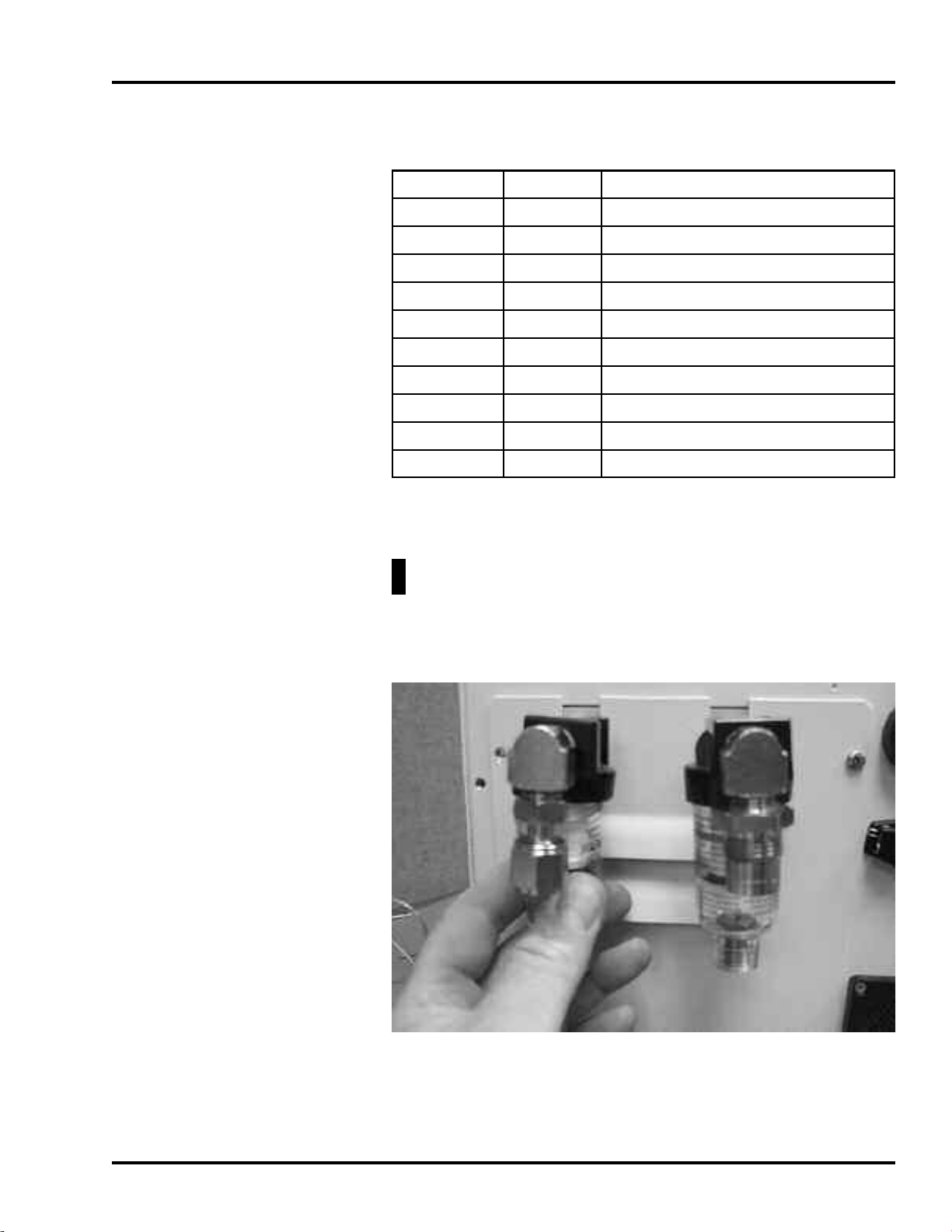
Inlet Water Trap Filters & O-ring Assembly
Inhalation Outlet Check Valve Diaphram
.
Figure 2-1 Inlet W
1
Unscrew the collection bowl from the inlet water trap.
2 Unscrew the filter holder.
SER360 A1106 2-3
ater Trap Filter Replacement
MAINTENANCE, OVERHAUL & SOFTWARE UPGRADE
3 Remove and replace the inlet filter and O-ring.
4 Reinstall the filter holder and reassemble the water trap
assembly.
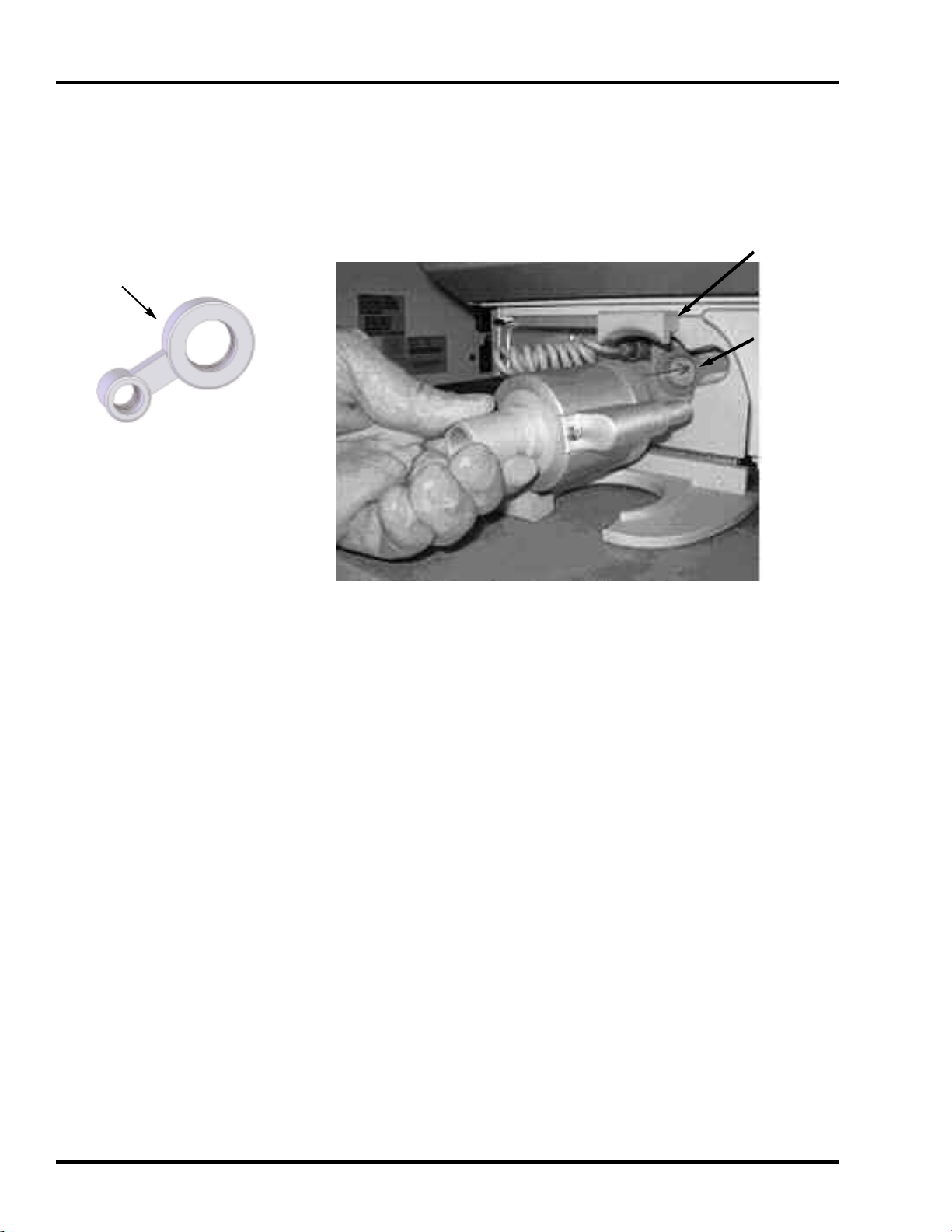
Adapter Lip
ADP2105M
Exhalation Valve Adapter
Retaining
Latch
Valve
Adapter
Figure 2-2 Exhalation Valve Adapter Replacement
1
Access the Exhalation Valve
Adapter by lifting the Retaining
Latch and removing the Exhalation Valve and Exhalation Flow
Sensor, see Figure 2-2 above.
2 To remove the silicon Exhalation Valve Adapter, use your finger
to grasp the Adapter and pull it straight out.
3 To replace the Exhalation Valve Adapter, orient the Adapter lip
towards the inside of the instrument and press into place.
4 Ensure that the Adapter is properly seated before re-installing
the Exhalation Valve and Exhalation Flow Sensor.
2-4 SER360 A1106
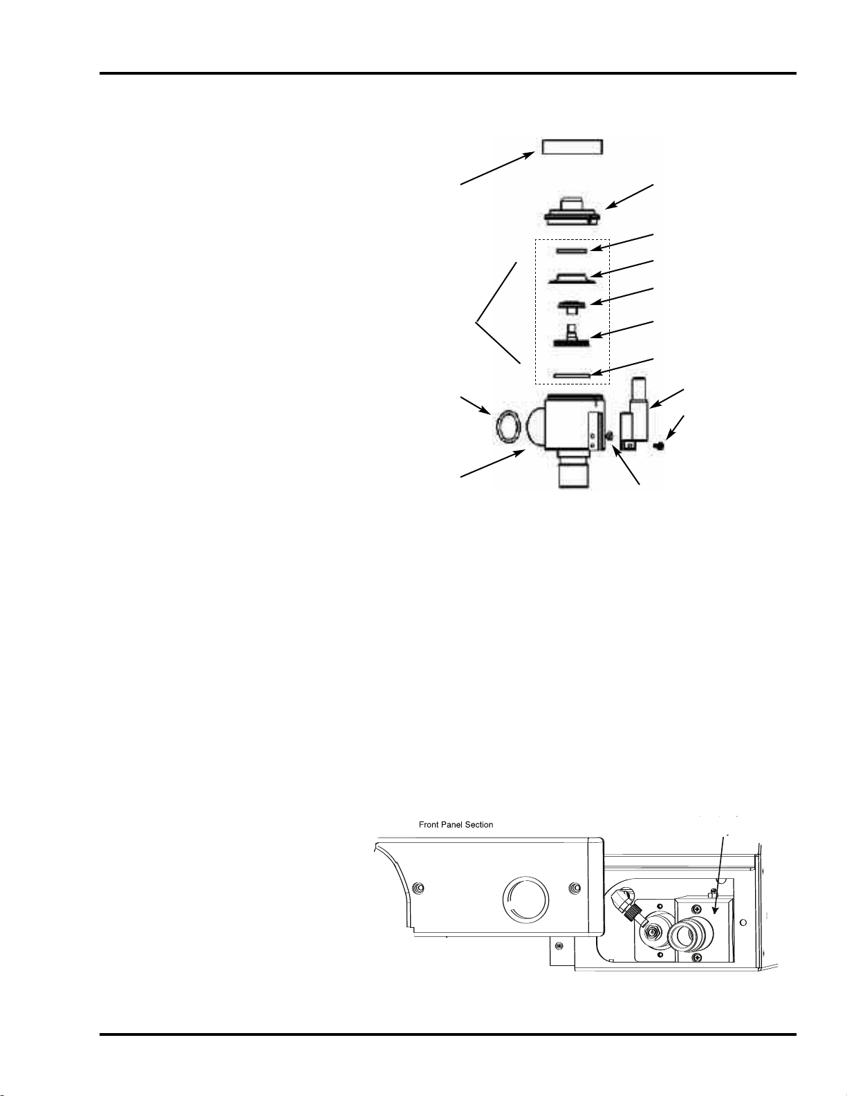
Exhalation Valve Diaphragm, Seal & O-Ring
Exh. Valve
Nut Collar
UT1802M
N
SECTION 2
xh. Valve Cap
E
CAP2112M
CAP1803M
IA1810M
D
Diaphragm
Poppet Assy
PPT1805A
ORG1200P
Exh. Valve Body
BDY2103M
PPT1800M
PPT1801M
SEL1800M
SLD2110M
SCR1830P
ORG2127P
Figure 2-3 Diaphragm, Seal & O-Ring Replacement
1
Unscrew the Exhalation Valve Nut Collar and lift off. Then lift
off the Exhalation Valve Cap and Diaphragm/Poppet Assy.
2 Disassemble the Diaphragm/Poppet Assy.
3 Reverse step 2 to install the new DIA1810M and SEL1800M.
4 Reverse step 1 to reassemble the Diaphragm/Poppet Assy,
Exhalation Valve Cap, and Exhalation Valve Nut Collar.
5 Locate and replace O-ring (ORG1200P) inside the Exhalation
alve Body
V
, see Figure 2-3.
Emergency Relief Diaphragm
Inh. Outlet
Figure 2-4 Inhalation Outlet Assembly
SER360 A1106 2-5
Assy

MAINTENANCE, OVERHAUL & SOFTWARE UPGRADE
Outlet Retaining
Screws
Emergency
Relief
Diaphragm
DIA1800M
Emergency
Valve Cap
Inhalation
Adapter
Inhalation
Outlet Block
Figure 2-5 Emergency Relief Diaphragm Replacement
1
Access the Inhalation Outlet
Assembly by removing the Lower
Right Front Panel, see Figure 2-4 above.
2 Remove the Inhalation Outlet Assembly by removing the two
retaining screws, see Figure 2-5 above.
3 Remove 4 screws from Emergency Valve Cap to expose the
Emergency Relief Valve.
4 Insert finger and pull the Emergency Relief Diaphragm
(DIA1800M) out of Inhalation Outlet Block.
5 Replace the Emergency Relief Diaphragm.
6 To reinstall components and assembly, reverse the above
procedure.
OVERHAUL PROCEDURES
WARNING: Disconnect electrical power, air and oxygen
sources before attempting any disassembly.
Inlet Water Trap Filter and O-ring Assembly
o replace the Inlet Filter and O-ring assemblies, follow the
T
procedures given in the Preventive Maintenance at the beginning
of this section.
2-6 SER360 A1106
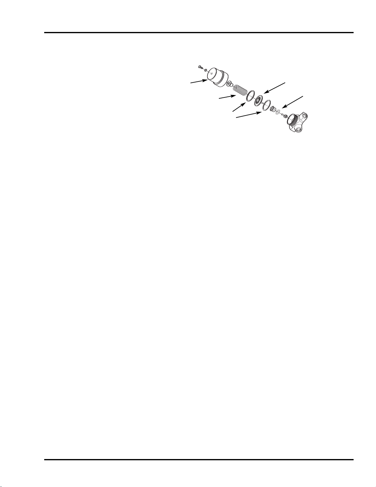
Air and Oxygen Inlet Regulator Rebuild
Cover
iaphragm
D
SECTION 2
Spring
S
lip Ring
O-Ring
Figure 2-6 Inlet Regulator Rebuild
To remove/install the Air and Oxygen Inlet Regulator, follow the
procedures in Section 4 of this manual, “Removal of Servo Valves,
Regulators, Inlet Block and Flow Sensor Block”.
NOTE: Inlet Regulators must be outside of the V
entilator for dis-
assembly and re-assembly.
To install the Air and Oxygen Inlet Regulators Rebuild Kits, refer to
Figure 2-6 and do the following:
1 Unscrew the brass cover from the regulator (no tool should be
needed) and remove the spring, diaphragm, diaphragm
washer, seat with O-ring, small spring, and ball (see Figure
2-6).
Exhalation Valve Adapter
2 Replace the used parts, reversing the disassembly, with the
parts from the Regulator Rebuild Kit P/N (RRK1800P).
NOTE: The Regulator must be in a vertical position in order to
reassemble the Kit components.
3 Install the Regulator brass cover, hand tight and ensure all
components are aligned.
NOTE: This procedure is the same for both the air and the oxygen
regulators.
o replace the Exhalation V
T
alve
Adapter
, follow the procedures
given in the Preventive Maintenance at the beginning of this
section.
SER360 A1106 2-7
MAINTENANCE, OVERHAUL & SOFTWARE UPGRADE
Exhalation Valve Diaphragm/Poppet Assembly
Refer to Drawing 2-3
1 Unscrew the Exhalation Valve Nut Collar and lift off. Then lift
off the Exhalation Valve Cap and Diaphragm/Poppet Assembly.
2 Replace complete Diaphragm/Poppet Assembly (p/n PPT1805A).
3 Reverse step 1 to reassemble the Diaphragm/Poppet Assembly,
Exhalation Valve Cap, and Exhalation Valve Nut Collar.
4 Locate and replace O-ring (ORG1200P) inside the Exhalation
Valve Body, see Figure 2-3.
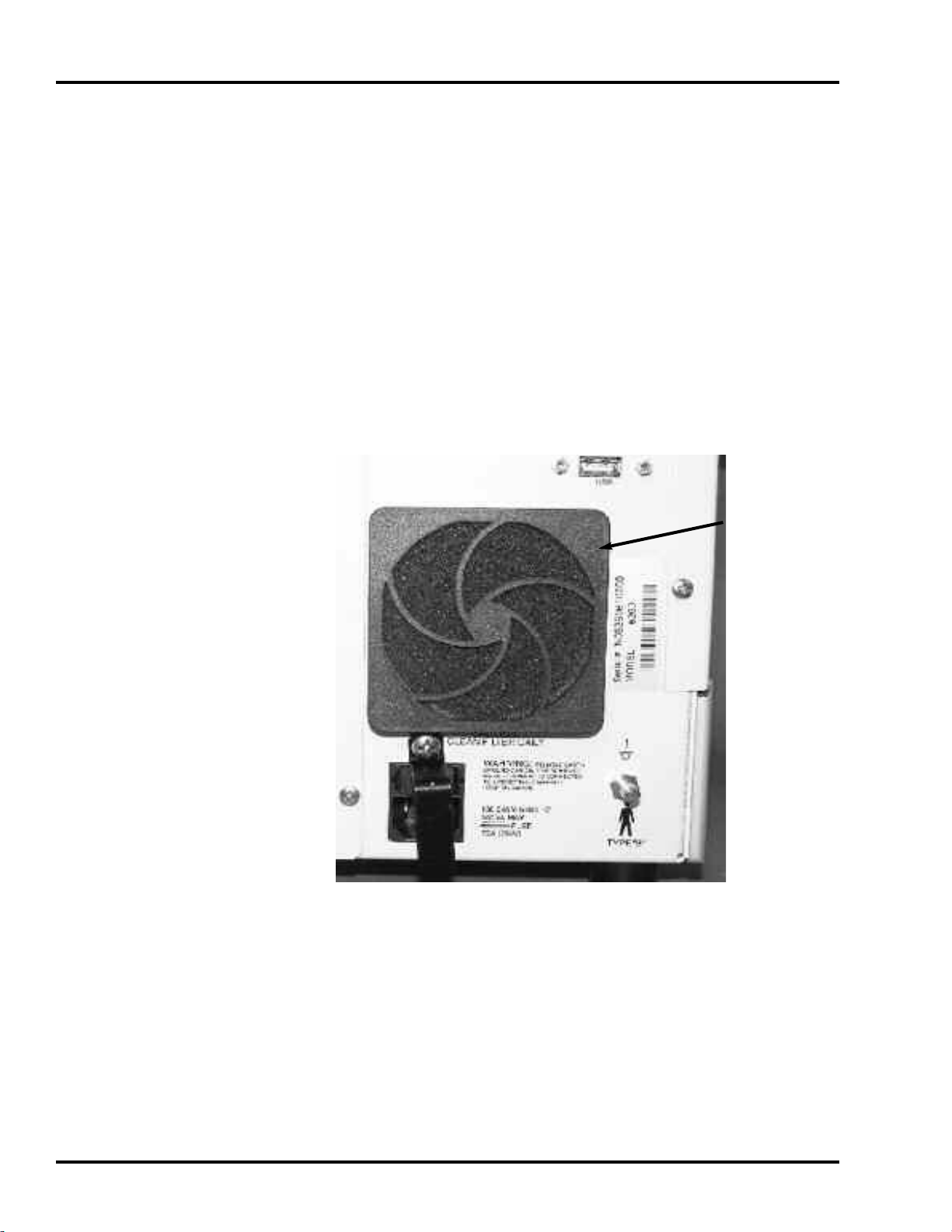
Cooling Fan Filter & Guard
Cooling Fan
Filter & Guard
Figure 2- 7 Filter and Guard Assembly Replacement
Replace the Cooling Fan Filter and Guard Assembly (GRD1800P),
see Figure 2-7.
2-8 SER360 A1106
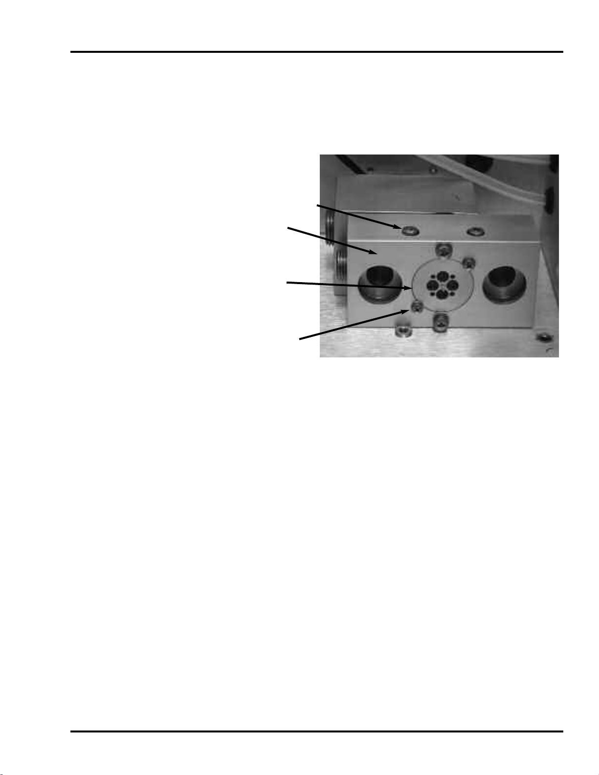
Emergency Relief Diaphragm
Emergency Intake Diaphragm
SECTION 2
To replace the Emergency Relief Diaphragm, follow the
procedures given in the Preventive Maintenance at the beginning
of this section.
Mixing Block
Retaining Screws (2)
Mixing Block
Emergency
Intake Valve
Emergency Intake
Valve Retaining
Screws (2)
Figure 2-8 Emergency Intake Diaphragm Replacement
Remove Top Cover following procedure in Section 4 of this
1
manual, “Removal of
Top cover”.
2 Remove Pneumatics Panel following procedure in Section 4 of
this Manual, “Removal of Pneumatics Panel Assembly”.
3 Remove Inspiratory Flow Sensors following procedure in
Section 4 of this manual, “Removal of Inspiratory Flow
Sensors”.
4 Remove two Emergency Intake Valve retaining screws, see
Figure 2-8
5 Remove the Emergency Intake V
above.
alve using Needle Nose
Pliers.
6 Replace the Emergency Intake Diaphragm (VLV100P) and
reinstall assembly by reversing procedure above.
SER360 A1106 2-9
MAINTENANCE, OVERHAUL & SOFTWARE UPGRADE
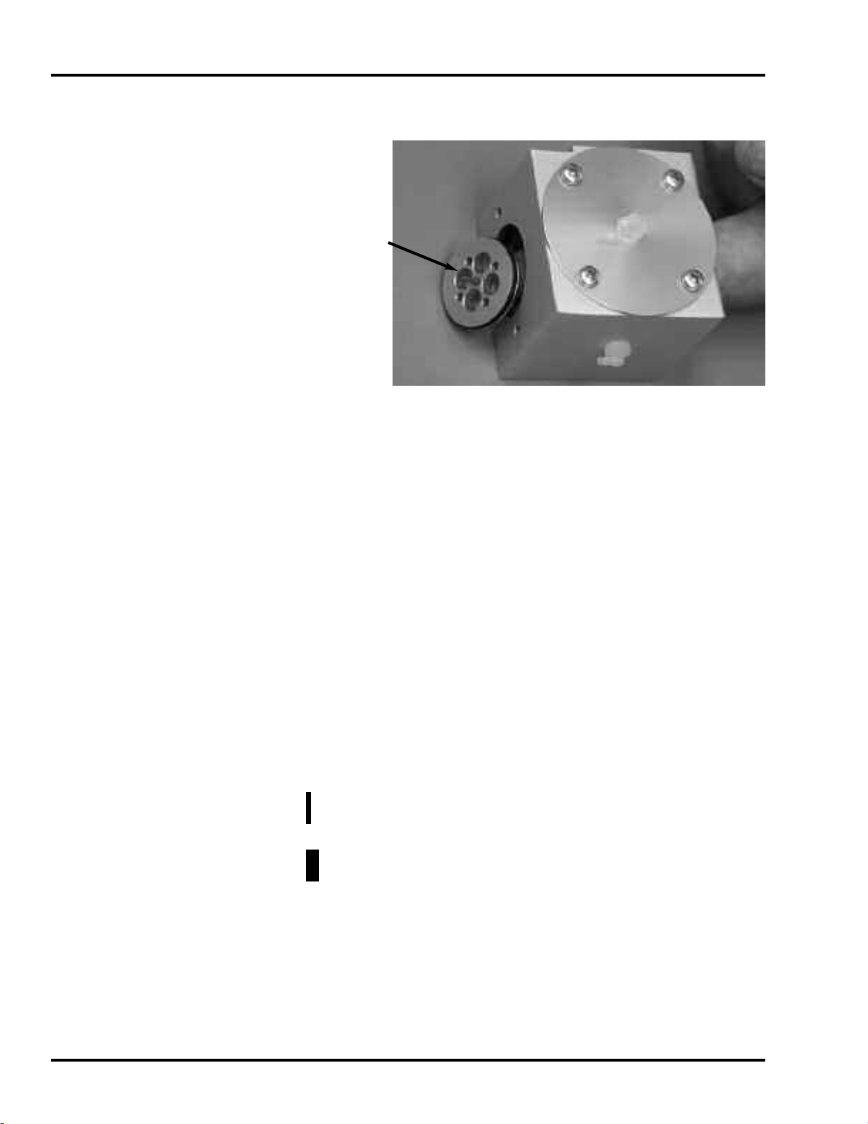
Inhalation Outlet Check Valve
Inhalation Outlet
Check Valve
Figure 2-9 Inhalation Outlet Check Valve
Remove the Mixing Block by removing the two retaining
1
screws, see Figure 2-8.
Internal Battery
2 Remove the Inhalation Adapter from the Inhalation Outlet
Assembly
3 Insert finger and push out the Inhalation Outlet Check V
see Figure 2-9.
4 Replace the Inhalation Outlet Check Valve Diaphragm
V2100M).
(VL
5 To reinstall components and assembly, reverse above
procedure.
o remove/install the Internal battery
T
Section 4 of this manual, “Removal of Internal Battery”.
Caution: T
any metal object (including tools) to touch battery connectors.
Warning: Observe correct polarity when reconnecting battery
connectors.
, see Figure 2-5.
alve,
, follow the procedures in
o avoid discharging battery voltage, do not allow
Tubing
The tubing inside the e360 ventilator does not need to be replaced
at any predetermined time interval; however, Newport is aware
that tubing may occasionally need replacing. During the overhaul
procedure, carefully inspect all tubing for degradation, cracks, or
2-10 SER360 A1106

brittleness. If the tubing indicates any of those symptoms, replace
as necessary.
If tubing needs to be replaced, please contact Customer Service
and order the e360 Tube Replacement Kit.
Refer to the e360 System Pneumatic Diagram (SPD2100A)
located in Appendix C to cut each tube to length and replace the
worn tubing in the e360 ventilator.
Upon Completion
After overhaul is completed, perform a complete electronic and
pneumatic calibration as outlined in Section 5 of this manual and
the Operation Verification Procedure as provided in Section 6.
e360 SOFTWARE UPGRADE PROCEDURE
GENERAL INFORMATION
SECTION 2
UPGRADE PROCEDURE
The following items are required for software upgrade:
• Latest Software on USB Flash Drive
• Software Upgrade Instructions
• NMI Reusable Patient Circuit (PBC340A) or equivalent
• Cap to plug end of patient circuit (CAP100P) or equivalent
Note: Follow this procedure to reload software after performing a
Main Board, Display Board or Single Board Computer component
replacement.
1 Confirm the e360 ventilator is OFF and connect
cord to the AC wall outlet (see Figure 2-13 for Power Entry
Module location).
2 Press and hold the “Accept” button and turn ON the power.
3 Release the “Accept” button when NMI Logo Screen is
displayed.
4 Wait for few minutes until the Software Download/Diagnostics
Mode screen is displayed, see Figure 2-11.
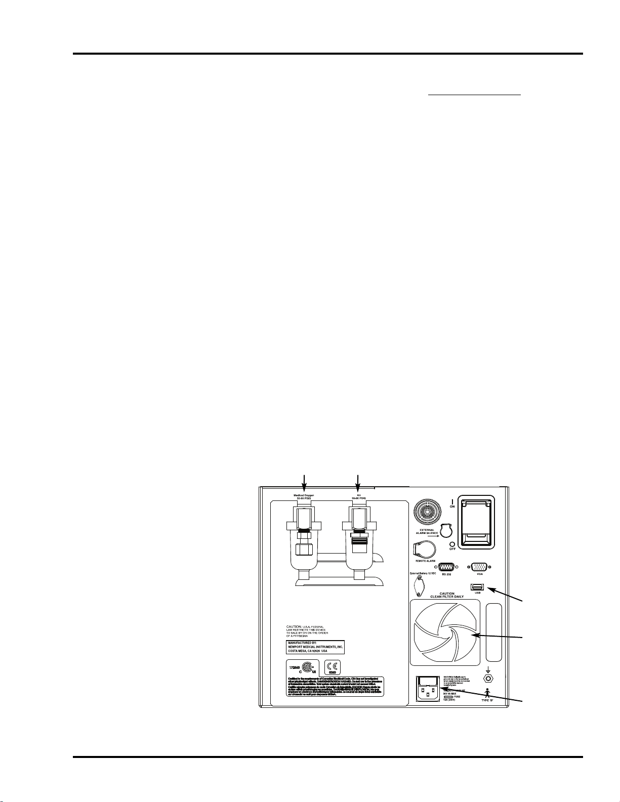
5 Connect USB Flash Drive (with latest software) to the USB
port on the Back Panel of the e360 ventilator (see Figure 2-13
for USB port location).
AC power
6 Press “Start Download” on touch screen (Figure 2-11). The
e360 ventilator will sound a short beep. “
Begin
“
download to complete.
SER360 A1106 2-11
” message on screen will change to a flashing message:
downloading….
” Wait 15 – 20 minutes for software
Touch Selection to
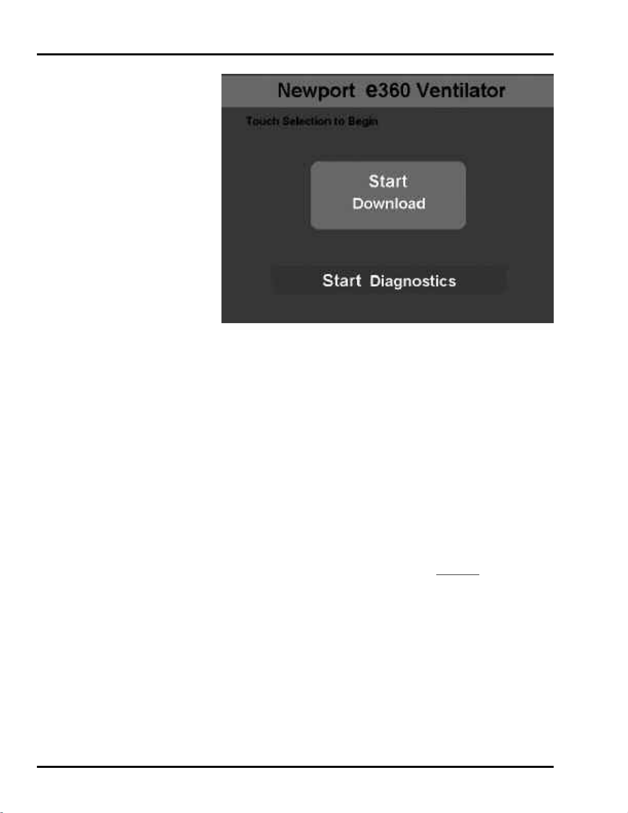
MAINTENANCE, OVERHAUL & SOFTWARE UPGRADE
Figure 2-11 Software Download/Diagnostics Mode Screen
7
When software download is completed, ventilator will sound a
short beep. “
the screen and flashing stops.
8 Turn OFF the power of the e360 ventilator.
9 Wait at least 10 seconds and turn the e360 ventilator power
back ON.
10 Wait until “Ventilation Standby” screen appears.
11 Press “Start V
12 NOTE: Because Air/O2gas supplies are not connected you
will get an “Air/O
software is installed correctly.
13 After “Start Ventilation” button is pressed, confirm that
“
Incompatible Software ….” Message does not show up on
the screen. If this message appears on the LCD touch screen,
then the software download was NOT completed successfully.
Repeat 1 – 6 again. If the same problem still remains, then
contact NMI representative for further assistance.
14 Press “Extended Functions” button on the Front control
panel.
Download Complete
entilating
2
” to begin ventilating.
Loss” alarm. Disregard alarm while verifying
” message will appear on
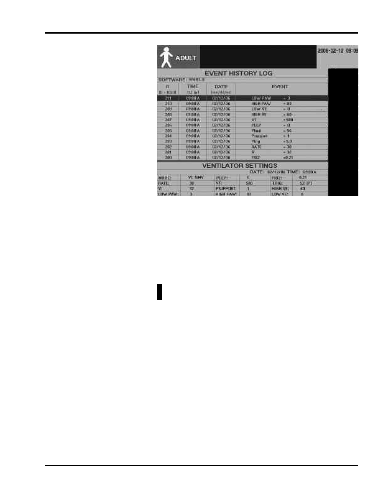
15 Press “Event History” button on LCD touch screen.
16 Confirm software is properly upgraded by checking software
version number (see Figure 2-12, left upper corner).
2-12 SER360 A1106
SECTION 2
Figure 2-12 Event History Log Screen
17
18 Remove USB Flash Drive from the USB Port on the back of
Circuit Check Test and Diagnostic
1 Turn OFF the power of the e360 ventilator.
2 Connect medical grade air source to Air Inlet on the Back
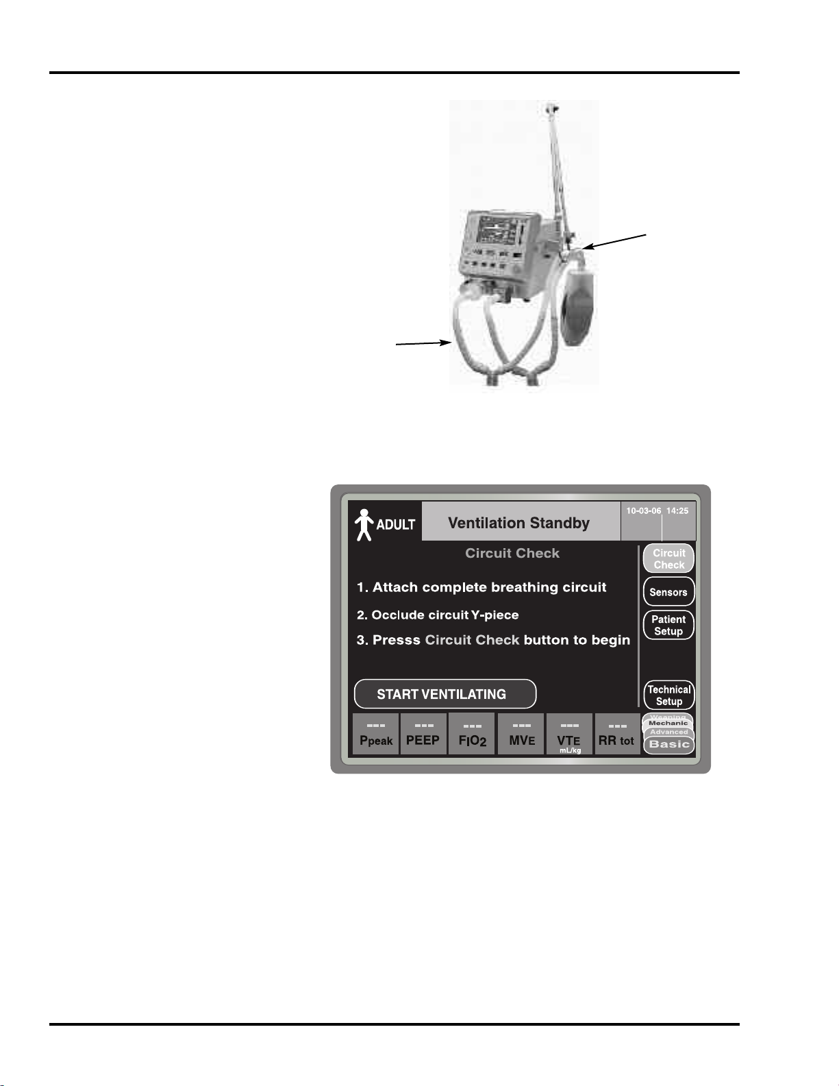
3 Connect appropriate patient circuit to the e360 ventilator as
4 Turn the power of the e360 ventilator back ON.
The new Software version is now downloaded successfully.
the e360 ventilator.
WARNING: Before returning the e360 ventilator back for patient
use after the software upgrade, you must perform the following:
Panel of the e360 ventilator and make sure that medical grade
air source can provide at least 30 psi and does not exceed
more than 90 psi. (see Figure 2-13 for
shown in Figure 2-14. Occlude the patient circuit using a CAP.
filter and test lung are not required for this instruction.
A
Air Inlet).
ait until “Ventilation Standby
5 W
6 Follow the instructions that appear on LCD touch screen as
shown in Figure 2-15.
SER360 A1106 2-13
” screen appears.

MAINTENANCE, OVERHAUL & SOFTWARE UPGRADE
7 Press “Circuit Check” button on LCD touch screen, and
Circuit Check Test in Progress
“
touch screen as shown in Figure 2-16.
” massage appears on LCD
8 When circuit test is completed successfully, “
PASSED
9 If circuit test failed, “
appears on LCD touch screen. Please check the breathing
circuit for leaks and press “
touch screen and repeat Circuit Check. If circuit check does
not pass, please contact NMI representative for further
assistant.
10 Press “Setup & Calibration” button on the Control Panel.
11Press “TECHNICAL” button on LCD touch screen, see Figure
2-17.
12 Press “Regional Settings” button on LCD touch screen, see
Figure 2-17.
13 Press “Altitude” button on LCD touch screen and “_ ft/_ m”
setting will start flashing.
14 While the numbers are flashing, rotate the Encoder
Adjustment Knob to change the Altitude level to where this
instruction is going to be performed. (For example if the
location is at the sea level, then set Altitude setting to “
”).
ft
” message appears on LCD touch screen.
Circuit Check FAILED
Circuit Check” button on LCD
Circuit Check
” message
0 m / 0
15 Press “Accept” button to set the new Altitude setting and
flashing will stop.
16 Wait for 15 ~ 20 seconds.
17 Turn “OFF” the power of the e360 ventilator.
18 Press and hold “Accept” button and then turn “ON” the
power of the e360 ventilator to enter into Software Download
screen on the e360 ventilator shown in Figure 2-11. “
button can be released once the ventilator sounds a short
beep.
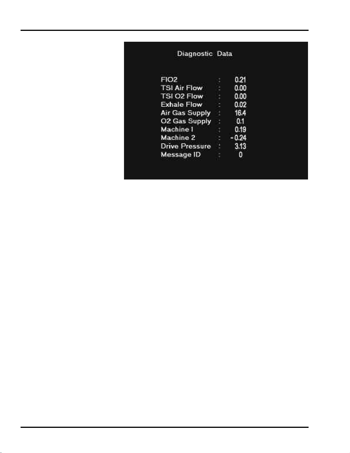
19 Press “Start Diagnostics” button on LCD touch screen and
the Diagnostic Data screen will appear as shown in Figure 2-
18.
20 Press “Trig Button” on the Control Panel. Rotate the Encoder
Adjustment Knob to change value in display window to “d9”
and press “
21 Occlude the breathing circuit from the y-piece using a CAP
(
Do not use test lung).
Accept” button.
Accept”
.
2-14 SER360 A1106
SECTION 2
Newport Model e360
Serial # XXXXXX
22 Press “Manual Inflation” button to start Exhalation Flow
Sensor calibration,
Air flow
:“ and “Exhale Flow:“ numbers start to increase
d9. Wait for
gradually and the air flow is delivered from the e360 ventilator.
It requires 6 ~ 10 minutes to complete Exhalation Flow Sensor
calibration, see Figure 2-18).
23 When flow delivered from the e360 ventilator stops and
“Message ID:” number changes to “41”, then the Exhalation
Flow Sensor calibration is successfully completed, see Figure
2-18.
24 Turn OFF the power of the e360 ventilator.
25 Disconnect medical grade air source from Air Inlet on the
Back Panel of the e360 ventilator.
26 Disconnect AC power cord from AC wall outlet.
27 Upon completion of the installation of software upgrade, you
must complete the attached “Newport e360 Ventilator
Software Update Form” with serial numbers, part numbers
and signatures and return it to Newport Regulatory
Department via Fax at +1.714.427. 0839.
30 sec ~ 1 minute
until “TSI
If you have any questions please contact Newport Technical
Service Department:
Tel: +1.714.427.5811 ext. 500, Fax: +1.714.427-0572
Email: TechService@NewportNMI.com
O2Inlet Air Inlet
USB
Connection
0
Cooling Fan
Filter
Power Entry
Module
Figure 2-13 Back Panel of e360 V
SER360 A1106 2-15
entilator
MAINTENANCE, OVERHAUL & SOFTWARE UPGRADE
Breathing Circuit
Figure 2-14 Patient Circuit Setup
Y-Piece
Figure 2-15 Ventilation Standby Screen
2-16 SER360 A1106

SECTION 2
Figure 2-16 Circuit Check Screen
Figure 2-17 Technical Screen
SER360 A1106 2-17
MAINTENANCE, OVERHAUL & SOFTWARE UPGRADE
Figure 2-18 Diagnostic Data Screen
2-18 SER360 A1106
 Loading...