

Page 1
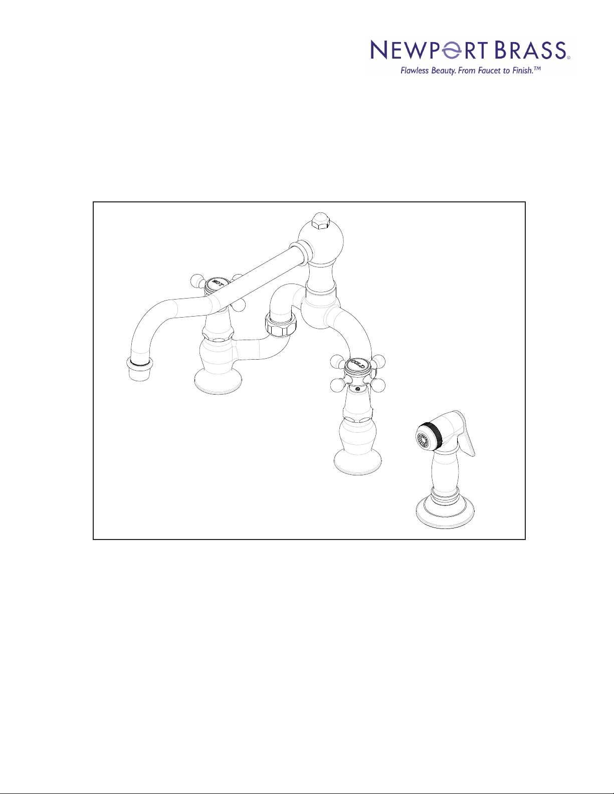
INSTALLATION INSTRUCTIONS
KITCHEN BRIDGE FAUCET
WITH SIDE SPRAY
Model No's: 9452-1
Congratulations on the purchase
of this Newport Brass product,
an excellent choice, that will give you
years of quality service and enhance
the look and style of your home.
Page 2

Recommended Installation by a Professional Plumbing Contractor
Note: The use of petroleum base plumbers putty on our products will nullify the warranty.
We recommend the use of clear silicone sealing materials. Use plumbers tape or equivalent
to seal all threaded joints. If mounting faucet to a stainless steel rim, an under-mounting support, (e.g. wood, appropriate size x 1/2” thick), should be utilized.
Recommended deck hole Ø1.25. Drill holes in mounting surface, center spacing for bridge
faucet to be between 8” - 9-11/16” and the side spray hole to be a minimum of 4-3/4” away
from the nearest mounting hole of faucet.
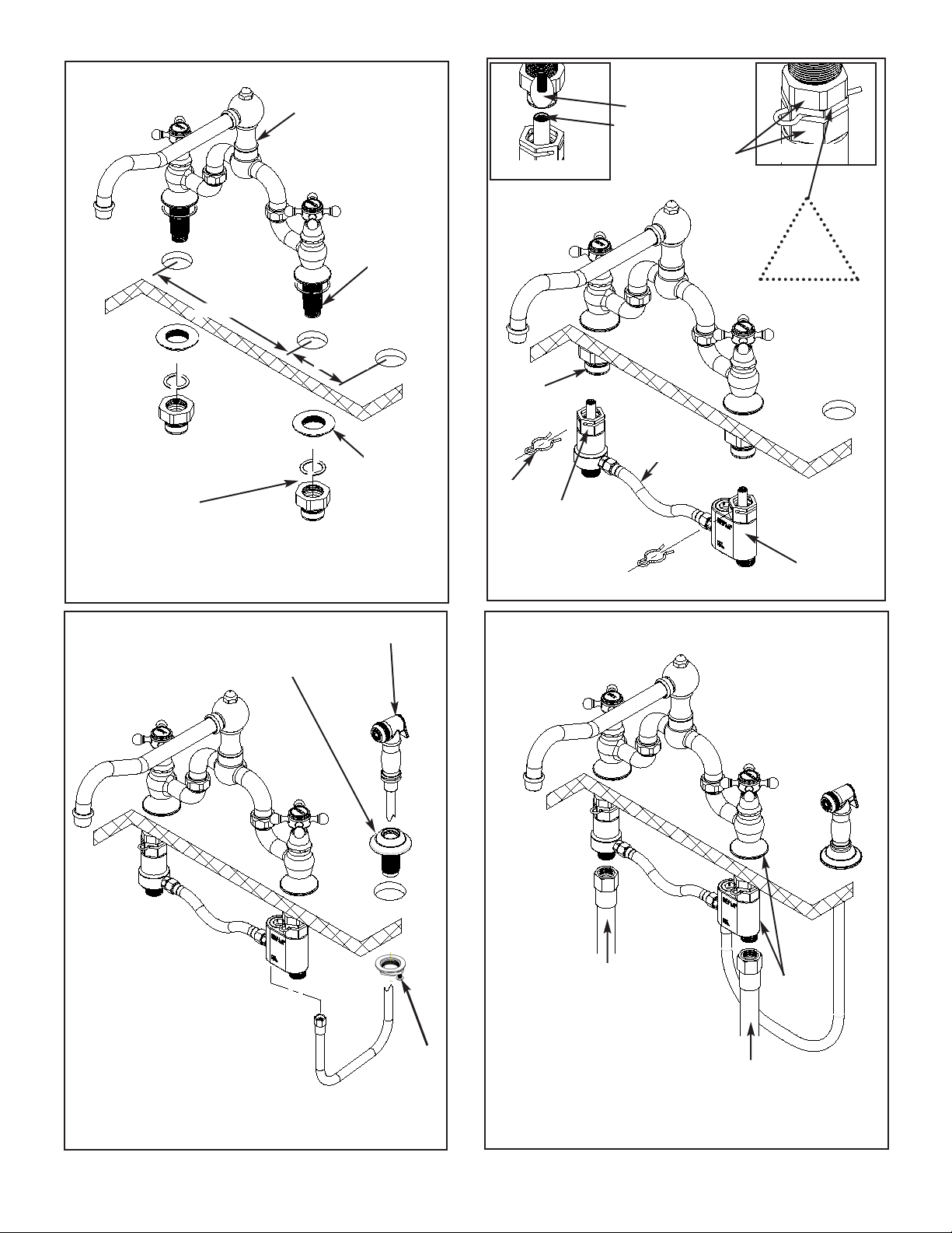
1. Place bridge faucet body through holes on mounting surface and secure into place with flange
nuts. See Fig. 1.
2. Using a 13/16" Drive Socket and socket extension as needed, torque the Quick connect
adapter with o-ring inserted to 6-12 LB-FT, onto the base of each shank. See Fig. 1.
3. Attach the diverter assembly to quick connect adapters - one side at a time (cold block
to the cold side of faucet) as follows: Reference Fig. 2
a. Engage stem connector on to broached stem extention, located inside shank. See
Detail A.
b. Rotate to align exterior hex of upper and lower adapters and mate together so there
is NO GAP between the two. See Detail B.
c. Check the alignment of the clip groove of upper adapter and the side slots of lower
adapter. Secure position by pushing clips though slot and into groove. See Fig. 2.
4. Place the side spray escutcheon with shank through mounting surface and secure into place
with mounting kit. See Fig. 3.
5. Drop side spray hose through escutcheon and thread onto diverter assembly. See Fig. 3.
6. Attach hot and cold water supply hoses (1/2-14NPS, not included) to appropriate valve, See
Fig. 4.
7. Adjust handle alignment as required by, removing set screws on handle base. Lift handle from
stem, rotate to proper alignment and lower back onto stem. Secure into place with setscrews.
8. Remove aerator from spout, turn on water supply, and flush valves until water is clear. Check
for leaks and make any final adjustments required. Re-attach aerator to the spout.
Important:
1. If the cold block of the diverter assembly is installed on the hot side of the faucet, the faucet
will have no flow.
Faucet can operate without side spray by replacing the side spray connection to cold block
2.
with 1/4-18 NPSM or 1/4-18 NPT thread cap.
NWP-9452-1
REV D
Page 3
8” - 9-11/16”
Bridge faucet
assembly
4-3/4” min.
Flange nut
Shank
Detail A
Clip
groove
Stem extention
Stem connection
Align hex-sides
(No gap between)
Diverter
assembly
Detail B
NO
GAP
Quick connect
adapter w/ o-ring
Figure 1
Escutcheon / shank
Side spray / hose
Clip
Figure 2
Slot
Cold
block
Figure 3
NWP-9452-1
REV D
Mounting
Kit
Hot water supply
1/2-14NPS
(Not included)
Figure 4
Cold
side
Cold water supply
1/2-14NPS
(Not included)
Page 4
Adjust Handle Alignment:
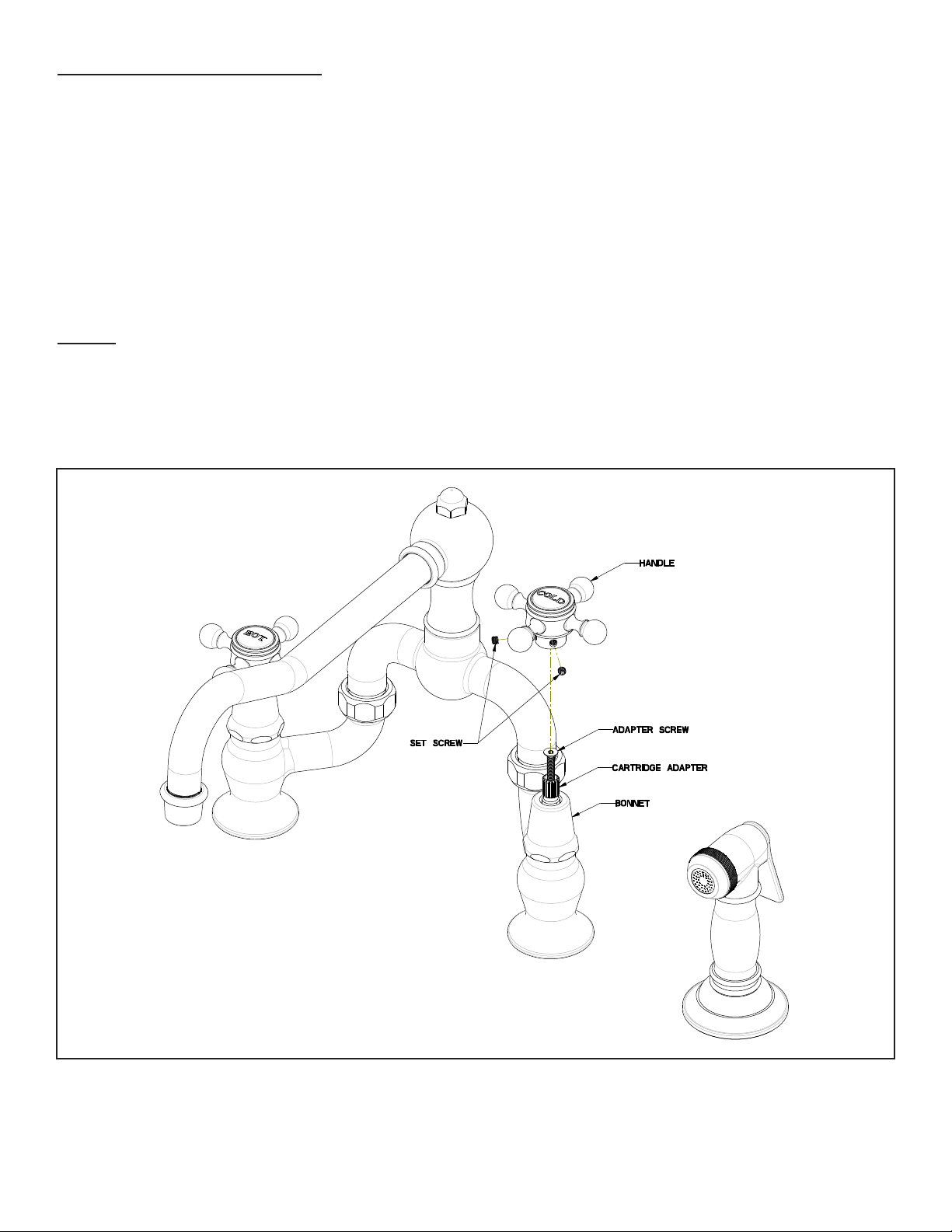
1. In Figure 5, ensure cartridges in full closed position and check HANDLE alignment. If the
HANDLE is not correctly aligned, temporary remove the HANDLE, loosen up (but do not
completely remove) the ADAPTER SCREW and rotate CARTRIDGE ADAPTER one tooth
clockwise (18 degrees), reassemble the HANDLE and recheck alignment. Repeat until the
HANDLE is aligned.
2. Remove the HANDLE and tighten the ADAPTER SCREW to firmly secure the CARTRIDGE
ADAPTER to cartridge. Reattach the HANDLE to the CARTRIDGE ADAPTER and secure the
HANDLE in place with set screw(s).
Note:
When reattaching the HANDLE, assure a small gap between HANDLE and BONNET to
prevent from metal-to-metal contact.
NWP-9452-1
REV D
Figure 5
2001 CARNEGIE AVE, SANTA ANA CA 92705
(949) 417-5207
WWW.NEWPORTBRASS.COM
09/30/2019
 Loading...