

Page 1
INSTALLATION INSTRUCTIONS
W
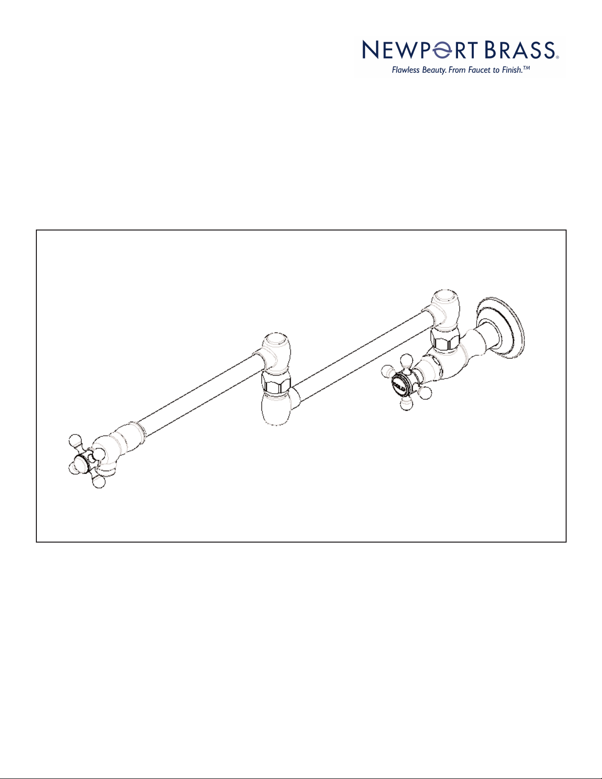
ALL MOUNT POT FILLER
Model No’s:
9481, 9482, 9485, 2470-5503, 1200-5503
1030-5503, 2500-5503, 2940-5503,
3170-5503, 3200-5503, 3210-5503,
3160-5503, 3180-5503, 3190-5503,
3220-5503,3290-5503
9481
Congratulations on the purchase
of your Newport Brass product,
an excellent choice, that will give you
years of quality service and enhance
the look and style of your home.
Page 2
Recommended Installation by a Professional Plumbing Contractor
Note:
I. Framing support is required for mounting flange to ensure sufficient strength of installation.
II. While drilling, extreme care should be taken to avoid damage to hidden electrical or plumbing lines.
III. Pot filler may get hot when arm is positioned above the stove’s burner. Swing the pot filler arm away
from the stove after use.
IV. The use of petroleum based plumbers putty on this product will nullify the warranty. We recommend
the use of silicone based sealing materials as needed.
Installation:
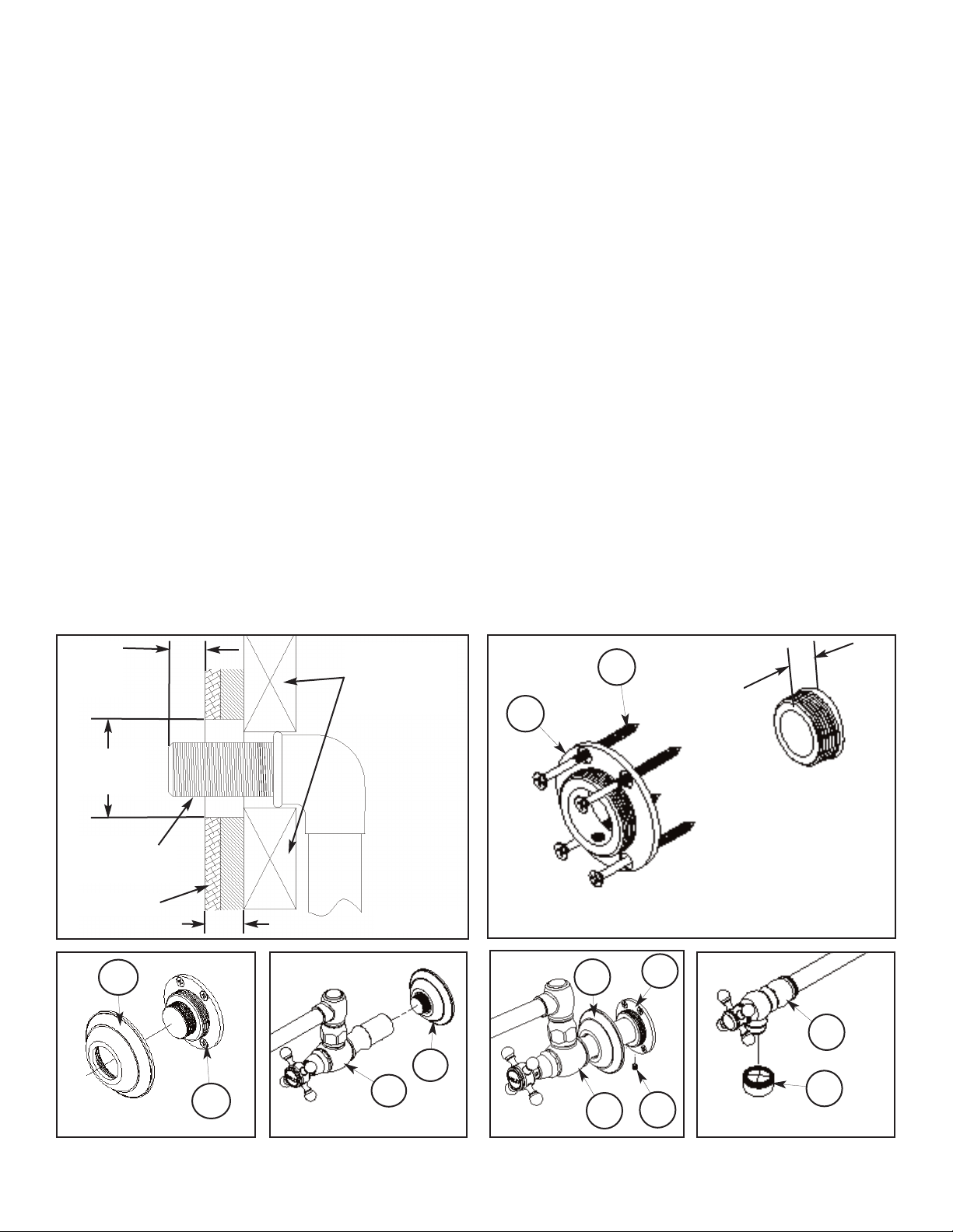
1. Shut off water supply. Tap into existing cold water supply and run to desired location on the wall. 1/2 NPT
connection (not supplied) is required and should protrude 1/2” out from finished wall. Apply thread
sealant to protruding end of 1/2 NPT. See Figure 1.
2. Center and secure the mounting FLANGE (1) over 1/2 NPT water supply with SCREWS (2) provided.
See Figure 2.
3. Temporarily thread ESCUTCHEON with O-RING (3) onto mounting FLANGE (1). See Figure 3.
4. Thread SPOUT ASSEMBLY (4) through ESCUTCHEON/O-RING (3) and onto 1/2 NPT water supply.
See Figure 4.
5. Remove ESCUTCHEON/O-RING (3) to expose mounting FLANGE (1). See Figure 5. Tighten the
SETSCREW (5) to secure SPOUT ASSEMBLY (4) to mounting FLANGE (1). Re-attach ESCUTCHEON/ORING (3) to mounting FLANGE (1) until flush against finish wall.
6. Remove AERATOR (7) from SPOUT ASSEMBLY (4). See Figure 6. Turn on water supply and check for leaks.
Repair as needed. Open valve and run water through SPOUT ASSEMBLY (4) to remove debris. Check for
leaks and make any final adjustments required. Re-attach AERATOR (7) to SPOUT (4).
1/2”
MAX
Ø1-3/16”
(30mm)
1/2 NPT
(not included)
Face of tile
1-1/2” MAX
3
Figure 3
Stud supports
for mounting
Flange
2
1/2”
MAX
1
Figure 1
3
1
Figure 2
4
3
1
Figure 4
4
Figure 5
4
5
Figure 6
7
NWP-9481 Rev E
EN-3
881a
2001 CARNEGIE AVE, SANTA ANA CA 92705
(949) 417-5207
WWW.NEWPORTBRASS.COM
11/07/19
 Loading...