

Page 1
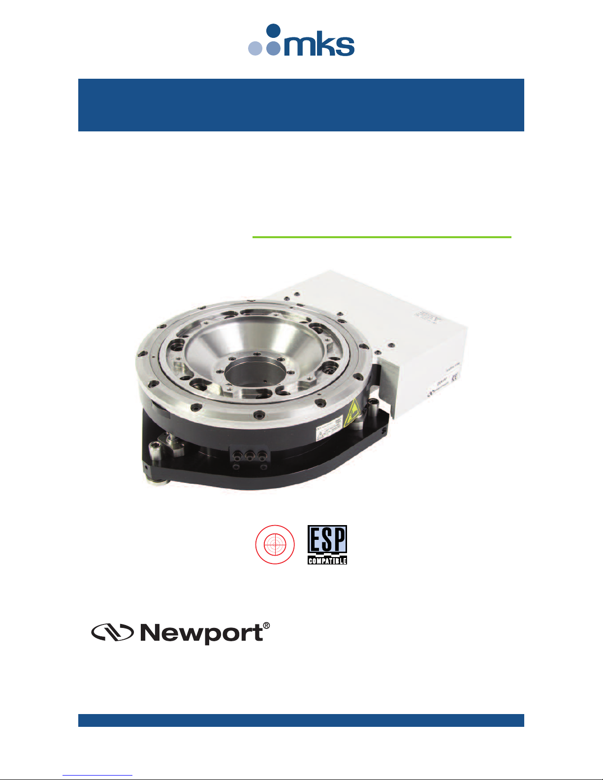
Integrated
Vertical and Rotation Stages
for Wafer Positioning
ZVR Series
USER’S MANUAL
G
U
A
R
A
N
T
E
E
D
S
P
E
C
I
F
I
C
A
T
I
O
N
S
Page 2

EDH0316En1031 — 11/18 ii
ZVR Series Integrated Vertical and Rotation Stages for Wafer Positioning
Warranty
Newport Corporation warrants this product to be free from defects in
material and workmanship for a period of 1 year from the date of
shipment. If found to be defective during the warranty period, the product
will either be repaired or replaced at Newport’s discretion.
To exercise this warranty, write or call your local Newport representative,
or contact Newport headquarters in Irvine, California. You will be given
prompt assistance and return instructions. Send the instrument,
transportation prepaid, to the indicated service facility. Repairs will be
made and the instrument returned, transportation prepaid. Repaired
products are warranted for the balance of the original warranty period, or
at least 90 days.
Limitation of Warranty
This warranty does not apply to defects resulting from modification or
misuse of any product or part.
This warranty is in lieu of all other warranties, expressed or implied,
including any implied warranty of merchantability or fitness for a
particular use. Newport Corporation shall not be liable for any indirect,
special, or consequential damages.
by Newport Corporation, Irvine, CA. All rights reserved.
Original instructions.
No part of this document may be reproduced or copied without the prior
written approval of Newport Corporation. This document is provided for
informa ti on only, and pro du ct specifications are subject to change without
notice. Any change will be reflected in future publishings.
CAUTION
Warranty does not apply to damages resulting from:
• Incorrect usage:
– Load on the stage greater than maximum specified load.
– Carriage speed higher than specified speed.
–Improper grounding.
¬ Connectors must be properly secured.
¬ When the load on the stage represents an electrical risk, it must
be connected to ground.
– Excessive or improper cantilever loads.
• Modification of the stage or any part thereof.
CAUTION
Please return equipment in
the original (or equivalent)
packing.
You will be responsible for
damage incurred from
inadequate packaging if the
original packaging is not
used.
© 2018
Page 3

iii EDH0316En1031 — 11/18
ZVR Series Integrated Vertical and Rotation Stages for Wafer Positioning
Table of Contents
Warranty .................................................................................................................ii
EC Declaration of Conformity...............................................................................v
Definitions and Symbols.......................................................................................vi
Warnings ...............................................................................................................vii
Caution .................................................................................................................viii
1.0 — Introduction.................................................................................1
2.0 — Description ...................................................................................2
2.1 Design Details ............................................................................................2
3.0 — Characteristics............................................................................3
3.1 Definitions ..................................................................................................3
3.2 Mechanical Specifications .......................................................................4
3.3 Load Specification Definitions.................................................................4
3.4 Load Characteristics and Stiffness .........................................................5
3.5 Stage Weights ............................................................................................5
4.0 — Drives and Motors ....................................................................5
4.1 Stepper Drive Axes ...................................................................................5
4.2 DC-Servo Drive Axis ..................................................................................6
4.3 Sensor Position..........................................................................................6
4.4 Feedback Signal Position .........................................................................7
4.5 Pinouts........................................................................................................7
4.6 MCAB-3 Cable ............................................................................................8
5.0 — Connection to Newport Controllers ................................9
5.1 Warnings on Controllers ..........................................................................9
5.2 Connection ...............................................................................................10
5.3 Cables .......................................................................................................10
5.4 MSCABLE-3 Cable ....................................................................................10
6.0 — Connection to Non-Newport Electronics ....................11
6.1 Connections .............................................................................................11
7.0 — Disabling Limit Switches of the Rotation Axis.........12
Page 4

EDH0316En1031 — 11/18 iv
ZVR Series Integrated Vertical and Rotation Stages for Wafer Positioning
8.0 — Dimensions.................................................................................13
8.1 ZVR-PP Stage............................................................................................13
8.2 ZVR-PC Stage ...........................................................................................14
9.0 — Maintenance ..............................................................................15
9.1 Maintenance ............................................................................................15
9.2 Repair .......................................................................................................15
9.3 Calibration ...............................................................................................15
Service Form .........................................................................................................17
Page 5
v EDH0316En1031 — 11/18
ZVR Series Integrated Vertical and Rotation Stages for Wafer Positioning
ZVR Series
EU Declaration of Conformity
following Annex II-1A
of Directive 2006/42/EC on machinery
The manufacturer:
MICRO-CONTROLE Spectra-Physics,
9, rue du Bois Sauvage
91055 Évry CEDEX, FRANCE
Hereby declares that the machinery:
y Description: " ZVR"
y Function: Integrated Vertical and Rotation Stage for Wafer Positioning
y Models: ZVR-PC/-PP
– the technical file of which was compiled by:
Mr Hervé LE COINTE , Quality Director,
MICRO-CONTROLE Spectra-Physics, Zone Industrielle - B.P.29
F-45340 Beaune La Rolande France
– complies with all the relevant provisions of the Directive 2006/42/EC on machinery.
– complies with all the relevant provisions of the Directive 2014/30/EU relating to electromagnetic compatibility.
– complies with all the relevant provisions of the Directive 2011/65/EU relating to RoHS2.
– was designed and built in accordance with the following harmonised standards:
y NF EN 61326-1:2013 « Electrical equipment for measurement, control and
laboratory use – EMC requirements – Part 1: General requirements »
y NF EN 55011:2010/A1:2011 Class A
– was designed and built in accordance with the following other standards:
y NF EN 61000-4-2
y NF EN 61000-4-3
y NF EN 61000-4-4
y NF EN 61000-4-5
y NF EN 61000-4-6
ORIGINAL DECLARATION
Done in Beaune La Rolande on 16 May 2017
Hervé LE COINTE
Quality Director
DC1-EN rev:A
EC Declaration of Conformity
Page 6
EDH0316En1031 — 11/18 vi
ZVR Series Integrated Vertical and Rotation Stages for Wafer Positioning
Definitions and Symbols
The following terms and symbols are used in this documentation and also
appear on the product where safety-related issues occur.
General Warning or Caution
The exclamation symbol may appear in warning and caution tables in this
document. This symbol designates an area where personal injury or
damage to the equipment is possible.
The following are definitions of the Warnings, Cautions and Notes that may
be used in this manual to call attention to important information regarding
personal safety, safety and preservation of the equipment, or important
tips.
WA RN IN G
Warning indicates a potentially dangerous situation which can result in
bodily harm or death.
CAUTION
Caution indicates a potentially hazardous situation which can result in
damage to product or equipment.
NOTE
Note indicates additional information that must be considered by the
user or operator.
European Union CE Mark
The presence of the CE Mark on Newport Corporation equipment means
that it has been designed, tested and certified as complying with all
applicable European Union (CE) regulations and recommendations.
Warnings and Cautions
ATTENTIO N
This stage is a Class A device. In a residential environment, this device
can cause electromagnetic interference. In this case, suitable measures
must be taken by the user.
Page 7
vii EDH0316En1031 — 11/18
ZVR Series Integrated Vertical and Rotation Stages for Wafer Positioning
Warnings
W
ARNING
The motion of objects of all types carries potential risks for operators.
Ensure the protection of operators by prohibiting access to the dangerous
area and by informing the personnel of the potential risks involved.
WA RN IN G
Do not use this stage when its motor is emitting smoke or is unusually
hot to the touch or is emitting any unusual odor or noise or is in any
other abnormal state.
Stop using the stage immediately, switch off the motor power and then
disconnect the electronics power supply.
After checking that smoke is no longer being emitted contact your
Newport service facility and request repairs. Never attempt to repair the
stage yourself as this can be dangerous.
WA RN IN G
Make sure that this stage is not exposed to moisture and that liquid does
not get into the stage.
Nevertheless, if any liquid has entered the stage, switch off the motor
power and then disconnect the electronics from power supply.
Contact your Newport service facility and request repairs.
WA RN IN G
Do not insert or drop objects into this stage, this may cause an electric
shock, or lock the drive.
Do not use this stage if any foreign objects have entered the stage.
Switch off the motor power and then disconnect the electronics power
supply.
Contact your Newport service facility for repairs.
WA RN IN G
Do not place this stage in unstable locations such as on a wobbly table or
sloping surface, where it may fall or tip over and cause injury.
If this stage has been dropped or the case has been damaged, switch off
the motor power and then disconnect the electronics power supply.
Contact your Newport service facility and request repairs.
WA RN IN G
Do not attempt to modify this stage; this may cause an electric shock or
downgrade its performance.
WA RN IN G
Do not exceed the usable depth indicated on the mounting holes (see
section “Dimensions”). Longer screws can damage the mechanics or
cause a short-circuit.
Page 8
EDH0316En1031 — 11/18 viii
ZVR Series Integrated Vertical and Rotation Stages for Wafer Positioning
Caution
C
AUTION
Do not place this stage in a hostile environment such as X-Rays, hard
UV,… or in any vacuum environment.
CAUTION
Do not place this stage in a location affected by dust, oil fumes, steam or
high humidity. This may cause an electric shock.
CAUTION
Do not leave this stage in places subject to extremely high temperatures
or low temperatures. This may cause an electric shock.
• Operating temperature: +10 to +35 °C
• Storage temperature: -10 to +40 °C (in its original packaging)
CAUTION
Do not move this stage if its motor power is on.
Make sure that the cable to the electronics is disconnected before
moving the stage. Failure to do so may damage the cable and cause an
electrical shock.
CAUTION
Be careful that the stage is not bumped when it is being carried. This
may cause it to malfunction.
CAUTION
When handling this stage, always unplug the equipment from the power
source for safety.
CAUTION
When the carriage is in its end-of-run position, it is strongly recommended
not to go beyond this point as this may damage the stage mechanism.
CAUTION
Contact your Newport service facility to request cleaning and
specification control every year.
Page 9

1 EDH0316En1031 — 11/18
ZVR Series Integrated Vertical and Rotation Stages for Wafer Positioning
Integrated Vertical and Rotation Stages
for Wafer Positioning
ZVR Series
1.0 —Introduction
This manual provides operating instructions for the ZVR series stages:
ZVR stage.
RECOMMENDATION
We recommend you read carefully the chapter “Connection to
electronics” before using the ZVR stage.
• ZVR-PC
(Stepper motor vertical, DC rotation)
• ZVR-PP
(Stepper motor vertical and rotation)
Page 10

EDH0316En1031 — 11/18 2
ZVR Series Integrated Vertical and Rotation Stages for Wafer Positioning
2.0 —Description
Newport’s new ZVR stages are integrated vertical and rotation positioning
s
tages designed primarily to precisely elevate and rotate wafer chucks,
and other samples or objects that would require adjustments to align the
object's orientation or to focus. These applications are not limited to
inspection or laser machining.
The ZVR's design takes the unconventional approach of most vertical
(
elevation) stage designs on the market today. The payload is supported
and driven at three points (separated by 120 degrees) along the outer
circumference of the stage. Ordinary designs use a single cam, wedge, or
screw located at the centre of the stage. Newport’s three point design
benefits applications that have slight to extreme unbalanced loading such
as wafer probing which can impart vertical forces at locations along the
outer edges of the chuck. Angular deflections due to these off-centre loads
are minimized and binding during vertical motion is eliminated. The ZVR’s
unique design also permits convenient height and tip/tilt adjustment, and
allows the centre of the stage to remain open through the bottom plate,
important for routing utilities to the wafer chuck. The clear aperture with
the integrated rotary stage is 50 mm in diameter.
Guiding the stage through its vertical trajectory are three miniature, ultraquiet, recirculating bearing guides. Like the drive screws that actuate
vertically, these three guides are located 120 degrees apart and are in-line
with the drive screws. The upper limit switch has a 4 mm adjustment
range enabling the user to set the upper limit of travel. The ZVR stages are
equipped with a hardware origin that serves as an absolute reference
(home) position.
For optimum performance and compatibility, use the Newport family of
controllers for these devices. The ZVR stages are ESP compatible allowing
the user to take advantage of Newport’s smart-stage features when used
with Newport controllers. Each stage axis is supplied with a 3-meter,
shielded cable with 25-pin sub-D connectors for direct connection to a
Newport motion controller (XPS, ESP301, SMC100) or other OEM motion
controller and driver.
2.1 Design Details
Base Material Aluminum and Stainless Steel
Bearings Stainless steel ball bearing
Drive Mechanism Vertical: 3 ballscrews with 1 mm pitch.
Rotation: Self-compensating, preloaded, precision worm gear with 1÷90 ratio
Reduction Gear ZVR-PC: Belt reduction 16÷44
Feedback ZVR-PC: 8,000 cts/rev. rotary encoder
Feedback (Vertical) ZVR-PP, ZVR-PC: Optional linear encoder 0.1 µm
Limit Switches Optical
±165° (Limit switches can be disabled)
Origin Centered on both rotation and vertical movements
Cable 3-meter, shielded cable
MTBF 20,000 hours
Page 11

3 EDH0316En1031 — 11/18
ZVR Series Integrated Vertical and Rotation Stages for Wafer Positioning
3.0 —Characteristics
3.1 Definitions
Specifications of our products are established in reference to ISO 230
standard part II “Determination of accuracy and repeatability of
positioning numerically controlled axes”.
T
his standard gives the definition of position uncertainty which depends
on the 3 following parameters:
Absolute Accuracy
Difference between ideal position and real position.
Accuracy
Difference between ideal position and real position after the compensation
of linear errors.
Linear errors include: cosine errors, inaccuracy of screw or linear scale
pitch, angular deviation at the measuring point (Abbe error) and thermal
expansion effects. All Newport motion electronics can compensate for
linear errors.
The relation between absolute accuracy and on-axis accuracy is as follows:
Absolute Accuracy = Accuracy + Correction Factor
x Travel
Repeatability
Ability of a system to achieve a commanded position over many attempts.
Reversal Value (Hysteresis)
Difference between actual position values obtained for a given target
position when approached from opposite directions.
Minimum Incremental Motion (MIM or Sensitivity)
The smallest increment of motion a device is capable of delivering
consistently and reliably.
Resolution
The smallest increment that a motion device can theoretically move
and/or detect. Resolution is not achievable, whereas MIM, is the real
output of a motion system.
Eccentricity
Displacement of the geometric center of a rotation stage from the rotation
axis in the plane defined by bearings.
Wobble
Tilt of rotation axis during rotation of a stage, measured on a reference
surface.
The testing of accuracy, repeatability, and reversal error are made
systematically with test equipment in controlled environment (20±1°C).
A linear cycle with 21 data points on the travel and 4 cycles in each
direction gives a total of 168 points.
Page 12

EDH0316En1031 — 11/18 4
ZVR Series Integrated Vertical and Rotation Stages for Wafer Positioning
3.2 Mechanical Specifications
CAUTION
To reach specifications stated, stages must be fixed on a plane surface
with a flatness of 50 µm.
3.3 Load Specification Definitions
Normal Load Capacity (Cz)
Maximum load a rotation stage can move while maintaining specifications.
This value is given with speed and acceleration specified for each rotation
stage, and with a load perpendicular to the bearings.
Off-Centered Load (Q)
Maximum cantilever-load a rotation stage can move: Q ≤ Cz ÷ (1 + D/a)
D: Cantilever distance.
a: Construction parameter.
G
U
A
R
A
N
T
E
E
D
S
P
E
C
I
F
I
C
A
T
I
O
N
S
Theta Rotation Stage Specifications ZVR-PP ZVR-PC
Travel Range (°) ±165 or continuous 360
Minimum Incremental Motion
(1)
(°) 0.0002 0.002
Accuracy
(3)
, Typical (Guaranteed) (°) ±10 (±17) ±10 (±15)
Unidirectional Repeatability
(3)
, Typical (Guaranteed) (°) ±0.001 (±0.0015) ±0.0005 (±0.0015)
Bidirectional Repeatability
(3)
, Typical (Guaranteed) (°) ±0.003 (±0.006) ±0.0013 (±0.003)
Max. Speed (°/s) 40 80
Wobble
(3)
, Typical (Guaranteed) (µrad) ±22 (±40)
Eccentricity
(
3)
, Typical (Guaranteed) (µm) ±2.2 (±4)
Z Vertical Stage Specifications
Travel (mm) 10
Minimum Incremental Motion
(
1)
(µm) 0.5
Accuracy
(3)
, Open Loop, Typical (Guaranteed) (µm) ±0.5 (±2)
Unidirectional Repeatability
(3)
, Open Loop, Typical (Guaranteed) (µm) ±0.4 (±2)
Bidirectional Repeatability
(
3)
, Open Loop, Typical (Guaranteed) (µm) ±1.2 (±2)
XY Cross Talk
(2)
, Typical (µm) ±0.1
Max. Speed (mm/s) 10
Pitch, Yaw
(
3)(4)
, Typical (Guaranteed) (µrad) ±17 (±35)
1
)
Depends on controller, see www.newport.com for more information.
2)
XY deviation when Z direction of motion is reversed.
3
)
For the definition of Typical and Guaranteed specifications see “Motion Basics Terminology & Standards” Tutorial
at www.newport.com
4
)
To obtain arcsec units, divide µrad value by 4.8.
Guaranteed and Typical Specifications
Guaranteed maximum performance values are verified per Newport's A167
metrology test procedure. For more information, please consult the
metrology tutorial section in the Newport catalog or at www.newport.com
Page 13

5 EDH0316En1031 — 11/18
ZVR Series Integrated Vertical and Rotation Stages for Wafer Positioning
3.4 Load Characteristics and Stiffness
3.5 Stage Weights
The stage weight below does not include the cables.
The weight difference between drive units is not significant.
4.0 —Drives and Motors
4.1 Stepper Drive Axes
The ZVR-PP rotation axis and both ZVR-PP and ZVR-PC vertical axes are
equipped with a stepper motor.
Stepper Motor Performance Specifications and Characteristics
Command Signals for the Stepper Motor
Weight [lb (kg)]
ZVR 9.3 (4.2)
3-meter MSCABLE-3 Cable 0.66 (0.3)
Cz, Normal center load capacity on bearings 100 N
Mz, Nominal torque 1 Nm
Jz, Max. load inertia 0.050 kg.m
2
Q, Off-center load (N) Q ≤ Cz ÷ (1 + D/40)
Where D = Cantilever distance (mm)
D
C
z
k
α
Z
Mz
Q
Resolution Speed Angle by Step RMS Current Resistance Inductance
(°) per Phase (A) (Ω) (mH)
ZVR-PP Rotaion Axis 0.0002°
(1)
40 °/s 1.8 0.71 1.7 2.8
ZVR-PP & PC Vertical Axis 50 nm
(1)
10 mm/s 1.8 0.5 4.8 4.6
1)
When used with an XPS motion controller.
0 2
-1
1
10.5 1.5
Step 1 2 3 4 5 8 7 8
+ Phase 1
+ + – – + + – –
– Phase 1
– – + + – – + +
+ Phase 2
– + + – – + + –
– Phase 2
+ – – + + – – +
Direction – MOTION
+
+ Phase 1
– Phase 1
+ Phase 2
– Phase 2
Direction +
Page 14

EDH0316En1031 — 11/18 6
ZVR Series Integrated Vertical and Rotation Stages for Wafer Positioning
4.2 DC-Servo Drive Axis
T
he ZVR-PC rotation axis is equipped with a DC-motor.
DC-Motor Performance Specifications and Characteristics
Command Signals for the DC-Motors
In the above drawings, + Motor signal is referenced to – Motor signal.
➀
When the stage moves in + Direction, the + Motor voltage is higher than
– Motor voltage.
➁
When the stage moves in – Direction, the + Motor voltage is lower than
– Motor voltage.
4.3 Sensor Position
End-of-Run and Mechanical Zero are 5 V open collector type.
The Index Pulse provides a repeatable Home Position at ±1 step.
CAUTION
“End-of-Run” and “Mechanical Zero” are active signals and should not
be connected to any other source.
Resolution Speed Nominal Max RMS Max. Peak Resistance Inductance Tachometer
(°) (°/s) Voltage (V) Current (A) Current (A) (Ω) (mH) Const. (V/krpm)
ZVR-PC Rotaion Axis 0.002
(1)
80 48 0.9 1.8 2.58 0.52 –
1)
When used with an XPS motion controller.
D
irection +
+V
+ Motor
– Motor
–V
MOTION Direction +
M
OTIONDirection –
– EOR Limit
Mechanical
Zero
Stage Travel Range
Index Pulse
Index Pulse
+
EOR Limit
H
ome Position (Origin)
a
t Center of Travel Range
Direction – MOTION Direction +
Page 15

7 EDH0316En1031 — 11/18
ZVR Series Integrated Vertical and Rotation Stages for Wafer Positioning
4.4 Feedback Signal Position
The incremental sensor consists of an optical scale and an encoder head.
When the carriage moves, the encoder head generates square signals in
quadrature and sends to pins #19, #20, #23 and #24 of the SUB-D25
connector.
“Encoder” and “Index Pulse” are “differential pair” (type RS-422) type
output signals. Using these signals permits a high immunity to noise.
Emission circuits generally used by Newport are 26LS31 or MC3487.
Reception circuits to use are 26LS32 or MC3486.
4.5 Pinouts
The pinout diagrams for the ZVR stages SUB-D15M connectors are shown
below.
Direction +
0
1
Encoder
Phase A
0
1
E
ncoder
P
hase A
1234
0
1
Encoder
Phase B
0
1
Encoder
Phase B
Direction – MOTION Direction +
SUD-D25 OR SUB-D15
Encoder Phase A 19 13
Encoder Phase A 23 6
Encoder Phase B 20 14
Encoder Phase B 24 7
Index Pulse Phase I 15 15
Index Pulse Phase I 25 8
21 12
22 5
N
EWPORT
S
TAGE
U
SER
C
ONNECTOR PIN #
O
utput Signals
Encoders
& Sensors
Power Supply
+5 V 5%
150 mA max.
0 V
}
8
15
9
1
ZVR-PP
(Rotation Axis)
1 + Phase 1
2 + Phase 2
3 Mechanical Zero
4 – End-of-Run
5 0 V
6 N.C.
7 N.C.
8 N.C.
9 – Phase 1
10 – Phase 2
11 + End-of-Run
12 +5 V
13 N.C.
14 N.C.
15 N.C.
ZVR-PP & ZVR-PC
(Vertical Axis)
1 + Phase 1
2 + Phase 2
3 Mechanical Zero
4 – End-of-Run
5 0 V
6 N.C.
7 N.C.
8 N.C.
9 – Phase 1
10 – Phase 2
11 + End-of-Run
12 +5 V
13 N.C.
14 N.C.
15 N.C.
ZVR-PC
(Rotation Axis)
1 N.C.
2 + Motor
3 Mechanical Zero
4 – End-of-Run
5 0 V
6 Encoder Phase /A
7 Encoder Phase /B
8 Index Pulse /I
9 N.C.
10 – Motor
11 + End-of-Run
12 +5 V
13 Encoder Phase A
14 Encoder Phase B
15 Index Pulse I
Page 16

EDH0316En1031 — 11/18 8
ZVR Series Integrated Vertical and Rotation Stages for Wafer Positioning
4.6 MCAB-3 Cable
Two 3-meter MCAB-3 cables are supplied with each ZVR stage (see section
5
.3: ”Cables”).
C
ONNECTED
T
O THE CAP
C
ONNECTED
T
O THE CAP
S
UB-D25M
C
ONNECTOR
1
2
3
4
5
6
7
8
1
4
2
2
2
1
1
6
1
9
2
3
2
0
2
4
1
5
2
5
1
7
1
8
1
3
S
UB-D25F
C
ONNECTOR
1
2
3
4
5
6
7
8
1
4
2
2
2
1
1
6
1
9
2
3
2
0
2
4
1
5
2
5
1
7
1
8
1
3
(0.6 MM2) WHITE 1
(
0.6 MM
2
)
WHITE 2
(0.6 MM
2
) WHITE 3
(0.6 MM2) WHITE 4
(0.6 MM2) WHITE 6
(
0.6 MM
2
)
WHITE 7
(0.6 MM
2
) WHITE 8
(0.6 MM2) WHITE 9
(0.6 MM2) WHITE 5
(0.6 MM2) WHITE 10
(0.6 MM2) WHITE 11
(
0.6 MM
2
)
WHITE 12
(0.09 MM
2
) WHITE
(0.09 MM2) BROWN
(0.09 MM2) GREEN
(
0.09 MM
2
)
YELLOW
(0.09 MM
2
) GREY
(0.09 MM2) PINK
(0.09 MM2) BLUE
(0.09 MM2) RED
(
0.09 MM
2
)
BLACK
(0.09 MM
2
) PURPLE
(0.09 MM2) ORANGE
(0.09 MM2) BLUE
(AWG20) WHITE 1
(
AWG20) WHITE 2
(AWG20) WHITE 3
(AWG20) WHITE 4
(AWG20) WHITE 6
(
AWG20) WHITE 7
(AWG20) WHITE 8
(AWG20) WHITE 9
(AWG20) WHITE 5
(AWG20) WHITE 10
(AWG20) WHITE 11
(
AWG20) WHITE 12
(AWG28) WHITE
(AWG28) BROWN
(AWG28) GREEN
(
AWG28) YELLOW
(AWG28) GREY
(AWG28) PINK
(AWG28) BLUE
(AWG28) RED
(
AWG28) BLACK
(AWG28) PURPLE
(AWG28) ORANGE
(AWG28) BLUE
Page 17

9 EDH0316En1031 — 11/18
ZVR Series Integrated Vertical and Rotation Stages for Wafer Positioning
5.0 —Connection to Newport Controllers
5.1 Warnings on Controllers
Controllers are intended for use by qualified personnel who recognize
shock hazards and are familiar with safety precautions required to avoid
p
ossible injury. Read the controller user’s manual carefully before
operating the instrument and pay attention to all written warnings and
cautions.
WA RN IN G
Disconnect the power plug under the following circumstances:
• If the power cord or any attached cables are frayed or damaged in
any way.
• If the power plug is damaged in any way.
• If the unit is exposed to rain, excessive moisture, or liquids are spilled
on the unit.
• If the unit has been dropped or the case is damaged.
• If you suspect service or repair is required.
• Whenever you clean the electronics unit.
CAUTION
To protect the unit from damage, be sure to:
• Keep all air vents free of dir t and dust.
• Keep all liquids away from the unit.
• Do not expose the unit to excessive moisture (85% humidity).
• Read this manual before using the unit for the first time.
WA RN IN G
All attachment plug receptacles in the vicinity of this unit are to be of
the grounding type and properly polarized.
Contact your electrician to check your receptacles.
WA RN IN G
This product is equipped with a 3-wire grounding type plug.
Any interruption of the grounding connection can create an electric
shock hazard.
If you are unable to insert the plug into your wall plug receptacle,
contact your electrician to perform the necessary alterations to ensure
that the green (green-yellow) wire is attached to ear th ground.
WA RN IN G
This product operates with voltages that can be lethal.
Pushing objects of any kind into cabinet slots or holes, or spilling any
liquid on the product, may touch hazardous voltage points or short out
parts.
Page 18

EDH0316En1031 — 11/18 10
ZVR Series Integrated Vertical and Rotation Stages for Wafer Positioning
5.2 Connection
There is a label on every stage indicating its part and serial numbers.
W
ARNING
Always turn the controller's power OFF before connecting to a stage.
NOTE
These stages are ESP compatible. Enhanced System Performance is
Newport's exclusive technology that enables Newport ESP motion
controllers to recognize the connected Newport ESP stage and upload
the stage parameters. This ensures that the user can operate the motion
system quickly and safely.
5.3 Cables
All ZVR stages are delivered with two MSCABLE-3 3-meter cables with a
SUB-D25M connector for direct connection to Newport Controllers.
5.4 MSCABLE-3 Cable
CABLE
CONNECTOR
STAGE
BENDING
STATIC CABLE: ≥.94 (24)
CABLE IN MOTION: ≥2.76 (70)
L
OCKING
K
NOBS
2
.24 (57)
DISCONNECTED
ø
.24
(
6)
SUB-D15 CONNECTOR SHOWN
DIMENSIONS IN INCHES (AND MILLIMETERS)
WA RN IN G
This cable is shielded correctly. For a correct operation, make sure to
lock connectors (ground continuity provided by the cable).
For applications where the standard 3-meter cable (MSCABLE-3) included
with your stage is not adequate, Newport offers a 10-m longer length cable
(MSCABLE-10) designed to ensure the integrity of your positioning
application.
REMARK
The cross section of the MSCAB-10 cable is different from the one of the
MSCABLE-3 cable to allow a longer length. The MSCAB-10 cable has the
same mechanical properties as the MCAB-10 cable.
These cables are specially shielded and terminated with Newport’s
standard SUB-D15 and SUB-D25 connectors.
WA RN IN G
Keep the motor cables at a safe distance from other electrical cables in
your environment to avoid potential cross talk.
Page 19

11 EDH0316En1031 — 11/18
ZVR Series Integrated Vertical and Rotation Stages for Wafer Positioning
6.0 —Connection to Non-Newport Electronics
6.1 Connections
WARNING
N
ewport is not responsible for malfunction or damage of ZVR stages
when used with non-Newport controllers.
WARNING
Newport guarantees
“”compliance of ZVR stages only if used with
Newport cables and controllers.
It is the customer's responsibility to modify the cable and take care of
sensor signal connections, when using the stage with non-Newport
controllers.
End-of-Runs and Mechanical Zero are open collector type with a 5.6 V
protective Zener diode.
I
i
n
max.: 16 mA
V max.: 5.25 V
NEWPORT
STAGE
5
.6 V
Page 20

EDH0316En1031 — 11/18 12
ZVR Series Integrated Vertical and Rotation Stages for Wafer Positioning
7.0 —Disabling Limit Switches of the Rotation Axis
The rotation stage of the ZVR is equipped with optical limit switches set to
±
165°. These limit switches can be disabled for continuous 360° rotation.
WARNING
The movement of objects of all types carries potential risks for operators.
Ensure the protection of operators by prohibiting access to the dangerous
area and by informing the personnel of the potential risks involved.
NOTE
To access and activate or inhibit the limit switches, the Z-stage of the
ZVR must be in its highest position.
Disconnect the ZVR, then set the limit switch as required.
ACTIVED LIMIT SWITCHES:
±165° TRAVEL
INHIBITED LIMIT SWITCHES:
CONTINUOUS TRAVEL
Page 21

13 EDH0316En1031 — 11/18
ZVR Series Integrated Vertical and Rotation Stages for Wafer Positioning
8.0 —Dimensions
8.1 ZVR-PP Stage
2.36
(60)
ø
1.97
(
50)
6.30
(160)
3 ADJUSTMENT
SCREWS M4 TO
ADJUST TOP PLATE
6
HOLES M6 THD
A
T 60° ON ø2.36 (60)
3 STRAIGHT UNIONS
FOR VACCUM TUBE ø.15 (4)
ø7.32
(186)
10.59
(269)
11.13
(282.8)
6.26
(159)
5.91
(150)
7
.32
(
186)
6.30
(160)
2 SUB-D15M CONNECTORS
.33 (8.4)
ADJUSTMENT
2.59 (65.5): +EOR
2.37 (60.2): MZ
2.16 (54.9): -EOR
MODEL SHOWN: ZVR-PP
DIMENSIONS IN INCHES (AND MILLIMETERS)
Page 22

EDH0316En1031 — 11/18 14
ZVR Series Integrated Vertical and Rotation Stages for Wafer Positioning
8.2 ZVR-PC Stage
2.36
(60)
ø
1.97
(
50)
6.30
(160)
3 ADJUSTMENT
SCREWS M4 TO
ADJUST TOP PLATE
6
HOLES M6 THD
A
T 60° ON ø2.36 (60)
3 STRAIGHT UNIONS
FOR VACCUM TUBE ø.15 (4)
ø7.32
(186)
10.59
(269)
11.22
(285)
6.26
(159)
5.91
(150)
7
.32
(
186)
6.30
(160)
2 SUB-D15M CONNECTORS
.33 (8.4)
ADJUSTMENT
2
.59 (65.5): +EOR
2
.37 (60.2): MZ
2
.16 (54.9): -EOR
M
ODEL SHOWN: ZVR-PC
DIMENSIONS IN INCHES (AND MILLIMETERS)
Page 23

15 EDH0316En1031 — 11/18
ZVR Series Integrated Vertical and Rotation Stages for Wafer Positioning
9.0 —Maintenance
R
ECOMMENDATION
Please contact Technical Sales Support team for recommendations on
application specific maintenance.
9.1 Maintenance
The ZVR stage requires no particular maintenance. Nevertheless, this is a
precision mechanical device that must be kept and operated with caution.
PRECAUTIONS
The ZVR stage must be used or stocked in a clean environment, without
dust, humidity, solvents or other substances.
RECOMMENDATION
It is recommended to return the stage to Newport for re-lubrication after
2000 hours of use.
If the ZVR stage is mounted on a workstation and cannot be easily
removed, please contact Newport's After Sales Service for further
instructions.
9.2 Repair
CAUTION
Never attempt to disassemble a component of the stage that has not
been covered in this manual.
To disassemble a non specified component can cause a malfunction of
the stage.
If you observe a malfunction in your stage, please contact us immediately
to arrange for a repair.
CAUTION
Any attempt to disassemble or repair a stage without prior
authorization will void your warranty.
9.3 Calibration
CAUTION
It is recommended to return your ZVR stage to Newport once a year for
recalibration to its original specifications.
Page 24

EDH0316En1031 — 11/18 16
ZVR Series Integrated Vertical and Rotation Stages for Wafer Positioning
Page 25

17 EDH0316En1031 — 11/18
Your Lo ca l Rep re se nt at iv e
Tel .:
F
ax:
N
ame:
Company:
Address:
Country:
P. O . N u m b e r :
Item(s) Being Returned:
Model #:
Description:
Reasons of return of goods (please list any specific problems):
R
eturn authorization #:
(Please obtain prior to return of item)
Date:
Phone Number:
Fax Number:
Serial #:
Service Form
Page 26

Visit Newport Online at:
www.newport.com
North America & Asia
Newport Corporation
1791 Deere Ave.
Irvine, CA 92606, USA
Sales
Tel.: (800) 222-6440
e-mail: sales@newport.com
Technical Support
Tel.: (800) 222-6440
e-mail: tech@newport.com
Service, RMAs & Returns
Tel.: (800) 222-6440
e-mail: service@newport.com
Europe
MICRO-CONTROLE Spectra-Physics S.A.S
9, rue du Bois Sauvage
91055 Évry CEDEX
France
Sales & Technical Support
Tel.: +33 (0)1.60.91.68.68
e-mail: france@newport.com
Service & Returns
Tel.: +33 (0)2.38.40.51.55
 Loading...