

Page 1
XPS-Q8
U
ser’s Manual,
Software Tools
and
Tutorial
V1.4
.x
Universal High-Performance
Motion Controller/Driver
Page 2

XPS-Q8 Universal High-Performance Motion Controller/Driver
Warranty
Newport Corporation warrants that this product will be free from defects in material and
workmanship and will comply with Newport’s published specifications at the time of
sale for a period of one year from date of shipment. If found to be defective during the
warranty period, the product will either be repaired or replaced at Newport's option.
To exercise this warranty, write or call your local Newport office or representative, or
contact Newport headquarters in Irvine, California. You will be given prompt assistance
and return instructions. Send the product, freight prepaid, to the indicated service
facility. Repairs will be made and the instrument returned freight prepaid. Repaired
products are warranted for the remainder of the original warranty period or 90 days,
whichever comes first.
Limitation of Warranty
The above warranties do not apply to products which have been repaired or modified
without Newport’s written approval, or products subjected to unusual physical, thermal
or electrical stress, improper installation, misuse, abuse, accident or negligence in use,
storage, transportation or handling. This warranty also does not apply to fuses, batteries,
or damage from battery leakage.
THIS WARRANTY IS IN LIEU OF ALL OTHER WARRANTIES, EXPRESSED OR
IMPLIED, INCLUDING ANY IMPLIED WARRANTY OF MERCHANTABILITY
OR FITNESS FOR A PARTICULAR USE. NEWPORT CORPORATION SHALL
NOT BE LIABLE FOR ANY INDIRECT, SPECIAL, OR CONSEQUENTIAL
DAMAGES RESULTING FROM THE PURCHASE OR USE OF ITS PRODUCTS.
©2017 by Newport Corporation, Irvine, CA. All rights reserved.
Original instructions.
No part of this document may be reproduced or copied without the prior written
approval of Newport Corporation. This document is provided for information only, and
product specifications are subject to change without notice. Any change will be
reflected in future publishings.
XPSDocumentation V1.4.x (EDH0301En1060 — 10/17) ii
Page 3

XPS-Q8 Universal High-Performance Motion Controller/Driver
Table of Contents
Waranty ............................................................................................................................ii
EU Declaration of Conformity ......................................................................................... x
Preface ............................................................................................................................. xi
User’s Manual
1.0 Introduction .................................................................................................. 1
1.1 Scope of the Manual ................................................................................................................ 1
1.2 Definitions and Symbols .......................................................................................................... 3
1.2.1 General Warning or Caution ................................................................................ 3
1.2.2 Electric Shock ...................................................................................................... 3
1.2.3 European Union CE Mark.................................................................................... 3
1.2.4 “ON” Symbol ....................................................................................................... 3
1.2.5 “OFF” Symbol ..................................................................................................... 3
1.3 Warnings and Cautions ............................................................................................................ 4
1.4 General Warnings and Cautions .............................................................................................. 4
2.0 System Overview........................................................................................... 6
2.1 Specifications ........................................................................................................................... 6
2.2 Drive Options .......................................................................................................................... 7
2.3 Compatible Newport Positioners and Drive Power Consumption ........................................... 8
2.4 XPS Hardware Overview......................................................................................................... 9
2.5 Front Panel Description ........................................................................................................... 9
2.6 Rear Panel Description .......................................................................................................... 10
2.6.1 Axis Connectors (AXIS 1 – AXIS 8) ................................................................. 10
2.7 Ethernet Configuration .......................................................................................................... 11
2.7.1 Communication Protocols .................................................................................. 11
2.7.2 Addressing ......................................................................................................... 12
2.8 Sockets, Multitasking and Multi-user Applications ............................................................... 12
2.9 Programming with TCL ......................................................................................................... 12
iii XPSDocumentation V1.4.x (EDH0301En1060 — 10/17)
Page 4

XPS-Q8 Universal High-Performance Motion Controller/Driver
3.0 Getting Started ............................................................................................ 14
3.1 Unpacking and Handling ....................................................................................................... 14
3.2 Inspection for Damage ........................................................................................................... 14
3.3 Packing List ........................................................................................................................... 14
3.4 System Setup ......................................................................................................................... 14
3.4.1 Installing Driver cards ........................................................................................ 15
3.4.2 Power ON .......................................................................................................... 15
3.5 Connecting to the XPS ........................................................................................................... 16
3.5.1 Straight through cables (black) .......................................................................... 16
3.5.2 Cross-over cables (gray) .................................................................................... 16
3.5.3 Direct Connection to the XPS Controller ........................................................... 17
3.5.4 Connecting the XPS to a Corporate Network using Static IP Configuration ..... 19
3.5.5 Configuring the XPS for Connection to a Corporate Network Using Dynamic IP
Configuration ................................................................................................. 21
3.5.6 Recovering a lost IP configuration ..................................................................... 24
3.6 Testing your XPS-PC Connection and Communication ........................................................ 26
3.7 Connecting the Stages ............................................................................................................ 27
3.8 Configuring the Controller ..................................................................................................... 28
3.8.1 Auto Configuration ............................................................................................ 29
3.8.2 Manual Configuration for Newport Positioners ................................................. 31
3.8.3 Manual Configuration for non Newport stages .................................................. 35
3.9 System Shut-Down ................................................................................................................ 35
Software Tools
4.0 Software Tools............................................................................................. 36
4.1 Software Tools Overview ...................................................................................................... 36
4.2 CONTROLLER CONFIGURATION – Users Management................................................. 37
4.3 CONTROLLER CONFIGURATION – IP Management ...................................................... 38
4.4 CONTROLLER CONFIGURATION – General ................................................................... 38
4.5 SYSTEM – Error file display ................................................................................................ 39
4.6 SYSTEM – Last error file display ......................................................................................... 39
4.7 SYSTEM – Auto Configuration ............................................................................................ 40
4.8 SYSTEM – Manual Configuration ........................................................................................ 40
4.9 SYSTEM – Manual Configuration – Gantries (Secondary Positioners) ................................ 44
4.9.1 Home search of gantries ..................................................................................... 45
4.9.2 Gantries with linear motors ................................................................................ 46
4.9.3 Gantries with linear motors and variable force ratio .......................................... 47
4.10 STAGE – Add from Data Base ............................................................................................ 49
XPSDocumentation V1.4.x (EDH0301En1060 — 10/17) iv
Page 5

XPS-Q8 Universal High-Performance Motion Controller/Driver
4.11
STAGE – Modify ................................................................................................................ 50
4.12 FRONT PANEL – Move ..................................................................................................... 52
4.13 FRONT PANEL – Jog ......................................................................................................... 53
4.14 FRONT PANEL – Spindle .................................................................................................. 53
4.15 FRONT PANEL – I/O View................................................................................................ 54
4.16 FRONT PANEL – I/O Set ................................................................................................... 54
4.17 FRONT PANEL – Positioner Errors ................................................................................... 55
4.18 FRONT PANEL – Hardware Status .................................................................................... 55
4.19 FRONT PANEL – Driver Status ......................................................................................... 56
4.20 TERMINAL ......................................................................................................................... 56
4.21 TUNING – Auto-Scaling ..................................................................................................... 59
4.22 TUNING – Auto-Tuning ..................................................................................................... 60
4.23 FUNCTIONAL TESTS ....................................................................................................... 63
4.24 FTP (File Transfer Protocol) Connection ............................................................................ 63
5.0 Maintenance and Service ........................................................................... 65
5.1 Enclosure Cleaning ................................................................................................................ 65
5.2 Obtaining Service .................................................................................................................. 65
5.3 Troubleshooting ..................................................................................................................... 65
5.4 Updating the Firmware Version of Your XPS Controller ..................................................... 66
Motion Tutorial
6.0 XPS Architecture ........................................................................................ 67
6.1 Introduction ........................................................................................................................... 67
6.2 State Diagrams ....................................................................................................................... 68
6.3 Motion Groups ....................................................................................................................... 70
6.3.1 Specific SingleAxis Group Features .................................................................. 71
6.3.2 Specific Spindle Group Features ........................................................................ 71
6.3.3 Specific XY Group Features .............................................................................. 71
6.3.4 Specific XYZ Group Features ............................................................................ 71
6.3.5 Specific MultipleAxes Features ......................................................................... 71
6.4 Native Units ........................................................................................................................... 71
7.0 Motion .......................................................................................................... 73
7.1 Motion Profiles ...................................................................................................................... 73
7.2 Home Search .......................................................................................................................... 75
7.3 Referencing State ................................................................................................................... 78
7.3.1 Move on sensor events ....................................................................................... 79
v XPSDocumentation V1.4.x (EDH0301En1060 — 10/17)
Page 6

XPS-Q8 Universal High-Performance Motion Controller/Driver
7.3.2 Moves of Certain Displacements ....................................................................... 80
7.3.3 Position Counter Resets ..................................................................................... 80
7.3.4 State Diagram .................................................................................................... 81
7.3.5 Example: MechanicalZeroAndIndexHomeSearch ............................................. 81
7.4 Move ...................................................................................................................................... 81
7.5 Motion Done .......................................................................................................................... 83
7.6 JOG ........................................................................................................................................ 85
7.7 Master Slave .......................................................................................................................... 86
7.8 Analog Tracking .................................................................................................................... 87
7.8.1 Analog Position Tracking .................................................................................. 88
7.8.2 Analog Velocity Tracking .................................................................................. 88
8.0 Trajectories ................................................................................................. 90
8.1 Line-Arc Trajectories ............................................................................................................. 90
8.1.1 Trajectory Terminology ..................................................................................... 90
8.1.2 Trajectory Conventions ...................................................................................... 91
8.1.3 Geometric Conventions ..................................................................................... 91
8.1.4 Defining Line-Arc Trajectory Elements ............................................................ 91
8.1.5 Define Lines ....................................................................................................... 92
8.1.6 Define Arcs ........................................................................................................ 93
8.1.7 Trajectory File Description ................................................................................ 93
8.1.8 Trajectory File Examples ................................................................................... 93
8.1.9 Trajectory Verification and Execution ............................................................... 94
8.1.10 Examples of the Use of the Functions.............................................................. 95
8.2 Splines ................................................................................................................................... 96
8.2.1 Trajectory Terminology ..................................................................................... 96
8.2.2 Trajectory Conventions ...................................................................................... 96
8.2.3 Geometric Conventions ..................................................................................... 96
8.2.4 Catmull-Rom Interpolating Splines ................................................................... 97
8.2.5 Trajectory Elements Arc Length Calculation..................................................... 97
8.2.6 Trajectory File Description ................................................................................ 98
8.2.7 Trajectory File Example .................................................................................... 98
8.2.8 Spline Trajectory Verification and Execution .................................................. 100
8.2.9 Examples .......................................................................................................... 101
8.3 PVT Trajectories .................................................................................................................. 101
8.3.1 Trajectory Terminology ................................................................................... 101
8.3.2 Trajectory Conventions .................................................................................... 101
8.3.3 Geometric Conventions ................................................................................... 102
8.3.4 PVT Interpolation ............................................................................................ 102
8.3.5 Influence of the Element Output Velocity to the Trajectory ............................ 103
8.3.6 Trajectory File Description .............................................................................. 104
8.3.7 Trajectory File Example .................................................................................. 105
8.3.8 PVT Trajectory Verification and Execution .................................................... 106
8.3.9 Examples of the Use of the functions .............................................................. 107
XPSDocumentation V1.4.x (EDH0301En1060 — 10/17) vi
Page 7

XPS-Q8 Universal High-Performance Motion Controller/Driver
9.0 Emergency Brake and Emergency Stop Cases ...................................... 108
10.0 Compensation.......................................................................................... 111
10.1 Backlash Compensation ..................................................................................................... 112
10.2 Linear Error Correction ..................................................................................................... 113
10.3 Positioner Mapping ............................................................................................................ 113
10.4 XY Mapping ...................................................................................................................... 116
10.5 XYZ Mapping .................................................................................................................... 118
10.6 “Yaw” Mapping (PP Firmware Version Only) .................................................................. 124
10.7 “Theta” Encoder and XY Correction ................................................................................. 127
11.0 Event Triggers......................................................................................... 128
11.1 Events ................................................................................................................................ 129
11.2 Actions ............................................................................................................................... 137
11.3 Functions ........................................................................................................................... 142
11.4 Examples ........................................................................................................................... 143
12.0 Data Gathering ....................................................................................... 147
12.1 Time-Based (Internal) Data Gathering .............................................................................. 148
12.2 Event-Based (Internal) Data Gathering .............................................................................. 150
12.3 Function-Based (Internal) Data Gathering ......................................................................... 153
12.4 Trigger-Based (External) Data Gathering .......................................................................... 153
13.0 Output Triggers ...................................................................................... 155
13.1 Triggers on Line-Arc Trajectories ..................................................................................... 155
13.2 Triggers on PVT Trajectories ............................................................................................ 157
13.3 Distance, Time Spaced Pulses or AquadB Position Compare ........................................... 158
13.3.1 Position compare settings and limits of use ................................................... 158
13.3.2 Even Distance Spaced Pulses Position Compare ........................................... 159
13.3.3 Compensated Position Compare .................................................................... 163
13.3.4 Time Spaced Pulses (Time Flasher) ............................................................... 166
13.3.5 AquadB Signals on PCO Connector .............................................................. 168
14.0 Control Loops ......................................................................................... 171
14.1 XPS Servo Loops ............................................................................................................... 171
14.1.1 Servo structure and Basics ............................................................................. 171
14.1.2 XPS PIDFF Architecture ............................................................................... 173
14.2 Filtering and Limitation ..................................................................................................... 177
14.3 Feed Forward Loops and Servo Tuning ............................................................................. 177
14.3.1 Corrector = PIDFFVelocity ........................................................................... 177
14.3.2 Corrector = PIDFFAcceleration ..................................................................... 179
14.3.3 Corrector = PIDDual FFVoltage .................................................................... 182
14.3.4 Corrector = PIPosition ................................................................................... 183
vii XPSDocumentation V1.4.x (EDH0301En1060 — 10/17)
Page 8

XPS-Q8 Universal High-Performance Motion Controller/Driver
15.0 Analog Encoder Calibration .................................................................. 185
16.0 Excitation Signal ..................................................................................... 190
16.1 Introduction........................................................................................................................ 190
16.2 How to Use the Excitation-Signal Function ...................................................................... 190
16.3 Group State Diagram ......................................................................................................... 191
16.4 Function Description.......................................................................................................... 191
17.0 Pre-Corrector Excitation Signal ............................................................ 192
17.1 Description ......................................................................................................................... 192
17.2 Pre-corrector excitation signal wave forms ....................................................................... 192
17.3 Technical Implementation ................................................................................................. 194
17.3.1 Use case ......................................................................................................... 194
17.3.2 Implementation .............................................................................................. 195
17.3.3 Group capsule state diagram modification ..................................................... 196
18.0 Introduction to XPS Programming ....................................................... 197
18.1 TCL Generator ................................................................................................................... 198
18.2 LabVIEW ........................................................................................................................... 199
18.3 DLL Drivers....................................................................................................................... 200
18.4 Running Processes in Parallel ............................................................................................ 201
XPSDocumentation V1.4.x (EDH0301En1060 — 10/17) viii
Page 9

XPS-Q8 Universal High-Performance Motion Controller/Driver
ix XPSDocumentation V1.4.x (EDH0301En1060 — 10/17)
Appendix
19.0 Appendix A: Hardware....................................................................... 204
19.1 Controller ........................................................................................................................... 204
19.2 Rear Panel Connectors ....................................................................................................... 205
19.3 Environmental Requirements............................................................................................. 205
20.0 Appendix B: General I/O Description .................................................. 206
20.1 Digital I/Os (All GPIO, Inhibit and Trigger In, and PCO Connectors) ............................... 206
20.1.1 Digital Inputs ................................................................................................. 206
20.1.2 Digital Outputs ............................................................................................... 207
20.2 Digital Encoder Inputs (Driver Boards & DRV00) ........................................................... 207
20.3 Digital Servitudes (Driver Boards, DRV00 & Analog Encoders Connectors) .................. 207
20.4 Analog Encoder Inputs (Analog Encoder Connectors) ...................................................... 207
20.5 Analog I/O (GPIO2 Connector) ......................................................................................... 208
20.5.1 Analog Inputs ................................................................................................. 208
20.5.2 Analog Outputs .............................................................................................. 208
21.0 Appendix C: Power Inhibit Connector ................................................. 209
22.0 Appendix D: GPIO Connectors ............................................................ 210
22.1 GPIO1 Connector .............................................................................................................. 2 1 0
22.2 GPIO2 Connector .............................................................................................................. 2 1 0
22.3 GPIO3 Connector .............................................................................................................. 2 1 1
22.4 GPIO4 Connector .............................................................................................................. 2 1 1
23.0 Appendix E: PCO Connector ................................................................ 212
24.0 Appendix F: Motor Driver Cards ......................................................... 213
24.1 DC and Stepper Motor Driver XPS-DRV01 ...................................................................... 213
24.2 Three phase AC brushless driver XPS-DRV02 ................................................................. 214
24.3 DC Motor Driver XPS-DRV03 ......................................................................................... 215
24.4 Pass-Through Board Connector (25-Pin D-Sub) XPS-DRV00 ......................................... 215
25.0 Appendix G: Analog Encoder Connector ............................................ 216
26.0 Appendix H: Trigger IN Connector ..................................................... 217
Service Form ...................................................................................................... 219
Page 10

XPS-Q8 Universal High-Performance Motion Controller/Driver
EU Declaration of Conformity
XPSDocumentation V1.4.x (EDH0301En1060 — 10/17) x
Page 11

XPS-Q8 Universal High-Performance Motion Controller/Driver
Preface
Confidentiality & Proprietary Rights
Reservation of Title
The Newport Programs and all materials furnished or produced in connection with them
(“Related Materials”) contain trade secrets of Newport and are for use only in the
manner expressly permitted. Newport claims and reserves all rights and benefits
afforded under law in the Programs provided by Newport Corporation.
Newport shall retain full ownership of Intellectual Property Rights in and to all
development, process, align or assembly technologies developed and other derivative
work that may be developed by Newport. Customer shall not challenge, or cause any
third party to challenge, the rights of Newport.
Preservation of Secrecy and Confidentiality and Restrictions to Access
Customer shall protect the Newport Programs and Related Materials as trade secrets of
Newport, and shall devote its best efforts to ensure that all its personnel protect the
Newport Programs as trade secrets of Newport Corporation. Customer shall not at any
time disclose Newport's trade secrets to any other person, firm, organization, or
employee that does not need (consistent with Customer's right of use hereunder) to
obtain access to the Newport Programs and Related Materials. These restrictions shall
not apply to information (1) generally known to the public or obtainable from public
sources; (2) readily apparent from the keyboard operations, visual display, or output
reports of the Programs; (3) previously in the possession of Customer or subsequently
developed or acquired without reliance on the Newport Programs; or (4) approved by
Newport for release without restriction.
Sales, Tech Support & Service
North America & Asia
Newport Corporation
1791 Deere Ave.
Irvine, CA 92606, USA
Sales
Tel.: (877) 835-9620
e-mail: sales@newport.com
Technical Support
Tel.: (800) 222-6440
e-mail: tech@newport.com
Service, RMAs & Returns
Tel.: (800) 222-6440
e-mail: service@newport.com
Europe
MICRO-CONTROLE Spectra-Physics S.A.S
9, rue du Bois Sauvage
91055 Évry CEDEX
France
Sales France
Tel.: +33 (0)1.60.91.68.68
e-mail: france@newport.com
Sales Germany
Tel.: +49 (0) 61 51 / 708 – 0
e-mail: germany@newport.com
Sales UK
Tel.: +44 (0)1635.521757
e-mail: uk@newport.com
Technical Support
e-mail: tech_europe@newport.com
Service & Returns
Tel.: +33 (0)2.38.40.51.55
xi XPSDocumentation V1.4.x (EDH0301En1060 — 10/17)
Page 12

XPS-Q8 Universal High-Performance Motion Controller/Driver
Service Information
The user should not attempt any maintenance or service of the XPS Series
Controller/Driver system beyond the procedures outlined in this manual. Any problem
that cannot be resolved should be referred to Newport Corporation. When calling
Newport regarding a problem, please provide the Tech Support representative with the
following information:
• Your contact information.
• System serial number or original order number.
• Description of problem.
• Environment in which the system is used.
• State of the system before the problem.
• Frequency and repeatability of problem.
• Can the product continue to operate with this problem?
• Can you identify anything that may have caused the problem?
Newport Corporation RMA Procedures
Any XPS Series Controller/Driver being returned to Newport must be assigned an RMA
number by Newport. Assignment of the RMA requires the item’s serial number.
Packaging
XPS Series Controller/Driver being returned under an RMA must be securely packaged
for shipment. If possible, re-use the original packaging.
XPSDocumentation V1.4.x (EDH0301En1060 — 10/17) xii
Page 13

XPS-Q8 Controller User’s Manual
1.0 Introduction
1.1 Scope of the Manual
The XPS is an extremely high-performance, easy to use, integrated motion
controller/driver offering high-speed communication through 10/100 Base-T Ethernet,
outstanding trajectory accuracy and powerful programming functionality. It combines
user-friendly web interfaces with advanced trajectory and synchronization features to
precisely control from the most basic to the most complex motion sequences. Multiple
digital and analog I/O's, triggers and supplemental encoder inputs provide users with
additional data acquisition, synchronization and control features that can improve the
most demanding motion applications.
To maximize the value of the XPS Controller/Driver system, it is important that users
become thoroughly familiar with available documentation:
The XPS Quick Start and XPS User’s Manual are delivered as paper copies with the
controller.
The Programmer’s, TCL, Software Drivers and Stage Configuration manuals are PDF
files accessible from the XPS web site.
DLLs and corresponding sources are available from the controller disk in the folder
Public/Drivers/DLL. DLLs can also be downloaded through the FTP.
LabVIEW VIs with examples are also available from the controller disk in the folder
Public/Drivers/LabView. They can also be downloaded through FTP.
To connect through FTP, please see chapter 5: “FTP connection”.
The first part of this manual serves as an introduction and also as a reference. It
includes:
1. Introduction
2. System Overview
3. Getting Started Guide
User’s Manual
1 XPSDocumentation V1.4.x (EDH0301En1060 — 10/17)
Page 14

XPS-Q8 Controller User’s Manual
The second part provides a detailed description of all software tools of the XPS
controller. It also includes an introduction to FTP connections and some general
guidelines for troubleshooting, maintenance and service:
4. Software Tools
5. FTP connection
6. Maintenance and Service
The third part provides an exhaustive description of the XPS architecture, its features
and capabilities. Complementing the programmer’s guide, this part
is educational and is
organized by features starting with the basics and getting to the more advanced features.
It provides a complete list of descriptions of different features including:
7. XPS Architecture
8. Motion
9. Trajectories
10. Compensation
11. Event Triggers
12. Data Gathering
13. Triggers
14. Control Loops
15. Analog Encoder Calibration
16. Introduction to XPS programming
XPSDocumentation V1.4.x (EDH0301En1060 — 10/17) 2
Page 15
XPS-Q8 Controller User’s Manual
1.2 Definitions and Symbols
The following terms and symbols are used in this documentation and also appear on the
XPS Series Controller/Driver where safety-related issues occur.
1.2.1 General Warning or Caution
Figure 1: General Warning or Caution Symbol.
The Exclamation Symbol in Figure 1 may appear in Warning and Caution tables in this
document. This symbol designates an area where personal injury or damage to the
equipment is possible.
1.2.2 Electric Shock
Figure 2: Electrical Shock Symbol.
The Electrical Shock Symbol in Figure 2 may appear on labels affixed to the XPS
Series Controller/Driver. This symbol indicates a hazard arising from dangerous
voltages. Any mishandling could result in damage to the equipment, personal injury, or
even death.
1.2.3 European Union CE Mark
Figure 3: CE Mark.
The presence of the CE Mark on Newport Corporation equipment means that it has
been designed, tested and certified to comply with all current and applicable European
Union (CE) regulations and recommendations.
1.2.4 “ON” Symbol
Figure 4: “ON” Symbol.
The “ON” Symbol in Figure 4 appears on the power switch of the XPS Series
Controller/Driver. This symbol represents the “Power On” condition.
1.2.5 “OFF” Symbol
Figure 5: “OFF” Symbol.
The “Off” Symbol in Figure 5 appears on the power switch of the XPS Series
Controller/Driver. This symbol represents the “Power Off” condition.
3 XPSDocumentation V1.4.x (EDH0301En1060 — 10/17)
Page 16
XPS-Q8 Controller User’s Manual
1.3 Warnings and Cautions
The following are definitions of the Warnings, Cautions and Notes that may be used in
this manual to call attention to important information regarding personal safety, safety
and preservation of the equipment, or important tips.
WARNING
Situation has the potential to cause bodily harm or death.
CAUTION
Situation has the potential to cause damage to property or
equipment.
WARNING
This product is equipped with a 3-wire grounding type plug. Any
interruption of the grounding connection can create an electric shock
hazard. If you are unable to insert the plug into your wall plug
receptacle, contact an electrician to perform the necessary alterations
to ensure that the green (green-yellow) wire is attached to earth
ground.
System earthing must be of type earthed neutral (TN-) as defined by
CEI60364.
NOTE
Additional information the user or operator should consider.
1.4 General Warnings and Cautions
The following general safety precautions must be observed during all phases of
operation of this equipment.
Failure to comply with these precautions or with specific warnings elsewhere in this
manual violates safety standards of design, manufacture, and the intended use of the
equipment.
• Heed all warnings on the unit and in the operating instructions.
• To prevent damage to the equipment, read the instructions in this manual for the
selection of the proper input voltage.
• Only plug the Controller/Driver unit into a grounded power outlet.
• Ensure that the equipment is properly grounded to earth ground through the
grounding lead of the AC power connector.
• Route power cords and cables where they are not likely to be damaged.
• Use Proper Power Cord
Use only the power cord specified for this product and certified for the country of
use.
• The system must be installed in such a way that the power switch and the power
connector remain accessible to the user.
• Disconnect or do not plug-in the AC power cord under the following conditions:
– If the AC power cord or any other attached cables are frayed or damaged.
– If the power plug or receptacle is damaged.
– If the unit is exposed to rain or excessive moisture, or liquids are spilled on it.
XPSDocumentation V1.4.x (EDH0301En1060 — 10/17) 4
Page 17

XPS-Q8 Controller User’s Manual
– If the unit has been dropped or the case is damaged.
– If the user suspects service or repair is required.
• Keep air vents free of dirt and dust and obstructions.
• Keep liquids away from unit.
• Do not expose equipment to excessive moisture (>85% humidity).
• Do not operate this equipment in an explosive atmosphere.
• Disconnect power before cleaning the Controller/Driver unit. Do not use liquid or
aerosol cleaners.
• Do not open the XPS Controller/Driver stand alone motion controller. There are no
user-serviceable parts inside the XPS Controller/Driver.
• Return equipment to Newport Corporation for service and repair.
• Dangerous voltages associated with the 100–240 VAC power supply are present
inside Controller/Driver unit. To avoid injury, do not touch exposed connections or
components while power is on.
• Follow precautions for static-sensitive devices when handling electronic circuits.
5 XPSDocumentation V1.4.x (EDH0301En1060 — 10/17)
Page 18

XPS-Q8 Controller User’s Manual
2.0 System Overview
2.1 Specifications
Number of Axes • 1 to 8 axes of stepper, DC brush, DC brushless motors or piezo-electric stacks using internal
drives
•
Other motion devices using external third-party drives
Communication Interfaces • Internet protocol TCP/IP
• One Ethernet 10/100 Base-T (RJ45 connector) with fixed IP address for local communication
• One Ethernet 10/100 Base-T (RJ45 connector) for networking, dynamic addressing with
DHCP and DNS
• Typically 0.3 ms from sending a tell position command to receiving the answer
• Optional XPS-RC remote control
Firmware Features
• Powerful and intuitive, object oriented command language
• Native user defined units (no need to program in encoder counts)
• Real time execution of custom tasks using TCL scripts
• Multi-user capability
• Concept of sockets for parallel processes
• Distance spaced trigger output pulses, max. 2.5 MHz rate, programmable filter
• Time spaced trigger output pulses, 0.02 Hz to 2.5 MHz rate, 50 ns accuracy
• Trigger output on trajectories with 100 µs resolution
• Data gathering at up to 8 kHz rate, up to 1,000,000 data entries
• User-defined “actions at events” monitored by the controller autonomously at a rate of 8 kHz
• User-definable system referencing with hardware position latch of reference signal transition
and “set current position to value” capability
• Axis position or speed controlled by analog input
• Axis position, speed or acceleration copied to analog output
• Trajectory precheck function replying with travel requirement and max. possible speed
• Auto-tuning and auto-scaling
Motion • Jogging mode including on-the fly changes of speed and acceleration
• Synchronized point-to-point
• Spindle motion (continuous motion with periodic position reset)
• Gantry mode including XY gantries with variable load ratio
• Line-arc mode (linear and circular interpolation incl. continuous path contouring)
• Splines (Catmull-Rom type)
• PVT (complex trajectory based on position, velocity and time coordinates)
• Analog tracking (using analog input as position or velocity command)
• Master-slave including single master-multiple slaves and custom gear ratio
Compensation • Linear error, Backlash, positioner error mapping
• XY and XYZ error mapping
• All corrections are taken into account on the servo loop
Servo Rate
• 8 kHz
Control Loop • Open loop, PI position, PIDFF velocity, PIDFF acceleration, PIDDualFF voltage
• Variable PID’s (PID values depending on distance to target position)
• Deadband threshold; Integration limit and integration time
• Derivative cut-off filter; 2 user-defined notch filters
XPSDocumentation V1.4.x (EDH0301En1060 — 10/17) 6
Page 19

XPS-Q8 Controller User’s Manual
I/O • 30 TTL inputs and 30 TTL outputs (open-collector)
• 4 synch. analog inputs ±10 V, 14 Bit
• 4 synch. uncommitted analog outputs, 16 Bit
• Watchdog timer and remote interlock
Trigger In • Hardware latch of all positions and all analog I/O’s; 8 kHz max. frequency
• <50 ns latency on positions
• <100 µs time jitter on analog I/O’s
Trigger Out • One high-speed position compare output per axes that can be either configured for position
synchronized pulses or for time synchronized pulses : <50 ns accuracy/latency, 2.5 MHz max.
rate
Dedicated Inputs Per Axis • RS-422 differential inputs for A, B and I, Max. 25 MHz, over-velocity and quadrature error
detection
• 1 Vpp analog encoder input up to x32768 interpolation used for servo; amplitude, phase and
offset correction; additional 2nd hardware interpolator used for synchronization; up to x200
interpolation
• Forward and reverse limit, home, error input
Dedicated Outputs Per Axis
(when using external drives)
2 channel 16-bit, ±10 V D/A
Drive enable, error output
Drive Capability
• Analog voltage, analog velocity, and analog acceleration (used with XPS-DRV01 and
XPS-DRV03 for DC brush motor control).
• Analog position (used with XPS-DRV01 for stepper motor control or with the XPS-DRVP1
for piezo control)
• Analog position (used with external drives for example 3rd party motors)
• Analog acceleration, sine acceleration and dual sine acceleration (used with XPS-DRV02 for
brushless motors control)
• Step and direction and +/- pulse mode for stepper motors (requires XPS-DRV00P and external
stepper motor driver)
• 500 W @ 230 VAC and 425 W @ 115 VAC total available power
AC Power Requirements • 100–240 VAC 60/50 Hz 10 A–5.5 A The controller should be connected to a power
installation that incorporates appropriate protection devices. Refer to the installation
requirements of your facility and local applicable Standards concerning the use of RCDs
(residual current device).
Dimensions (W x D x H)
•
19” – 4U, L: 508 mm
Weight
• 15 kg max
2.2 Drive Options
The XPS controller is capable of driving up to 8 axes of most Newport positioners using
driver cards that slide through the back of the chassis. These factory-tested drives are
powered by an internal 500 W power supply, which is independent of the controller
power supply. When used with Newport ESP stages, the configuration of the driver
cards is easy using the auto-configuration utility software. Advanced users can also
manually develop their own configuration files optimized for specific applications.
The XPS-DRV01 is a software configurable PWM amplifier that is compatible with
most of Newport’s and other companies’ DC brush and stepper motor positioners.
The XPS-DRV01 motor driver supplies a maximum current of 3 Amps and 48 Volts. It
has the capability to drive bipolar stepper motors in microstep mode (sine/cosine
commutation) and DC brush motors in velocity mode, for motors with tachometer, or
voltage mode, for motors without tachometer. Programmable gains and a programmable
PWM switching frequency up to 300 kHz allow a very fine adjustment of the driver to
the motor. For added safety, a programmable over-current protection setting is also
available.
7 XPSDocumentation V1.4.x (EDH0301En1060 — 10/17)
Page 20

XPS-Q8 Controller User’s Manual
The XPS-DRV02 is a software configurable PWM amplifier for 3-phase brushless
motors. It has been optimized for performance with XM, ILS-LM, IMS-LM linear
motor stages and RGV direct drive rotation stages. The XPS-DRV02 supplies a 100
kHz PWM output with a maximum output current of 5 A per phase and 44 Vpp. The
XPS-DRV02 requires 1 Vpp analog encoder input signals used also for motor
commutation. Motor initialization is done by a special routine measures the magnetic
position without the need for Hall or other sensors.
The XPS-DRV03 is a fully digital, programmable PWM-amplifier that has been
optimized for use with high-performance DC motors. The high switching frequency of
100 kHz and appropriate filter technologies minimize noise to enable ultra-precision
positioning in the nm-range. The XPS-DRV03 supplies a maximum current of 5 Amps
and 48 Volts. It is capable of driving DC motors in velocity mode (for motors with
tachometer), in voltage mode (for motors without tachometer), and in current mode (for
torque motors). All parameters are programmable in physical units (for instance the
bandwidth of the velocity loop). Furthermore, the XPS-DRV03 features individual
limits for the rms current and the peak current.
The XPS-DRVP1 is a programmable driver card for Newport's NanoPositioning line of
piezoelectric stack stages. This driver card has a range of -10 to 150 VDC with 30 mA
continuous. The drive features a 4 kHz update rate and resolution of 16 bits ADC and
DAC. It also accepts strain gage position feedback.
The XPS-DRV00 and XPS-DRV00P pass-through module can be used to pass control
signals to other external third-party amplifiers (drivers). By setting the controller’s dual
DAC output to either analog position, analog stepper position, analog velocity, analog
voltage or analog acceleration (including sine commutation), the XPS is capable of
controlling almost any motion device including 3
rd
party brushless motors and voice
coils.
In addition to conventional digital AquadB feedback encoder interface, the XPS
controller also features a high-performance analog encoder input (1 Vpp Heidenhain
standard) on each axis. An ultra-high resolution, very low noise, encoder signal
interpolator converts the sine-wave input to an exact position value with a signal
subdivision up to 32,768-fold. For example, when used with a scale with 4 µm signal
period the resolution can be as fine as 0.122 nm. This interpolator can be used for
accurate position feedback on the servo corrector of the system. An additional hardware
interpolator with 40 MHz clock frequency and programmable signal subdivision up to
200-fold is used for synchronization purposes. This fast interpolator latches the position
directly with less than 50 ns latency and provides a much higher level of precision for
synchronization than alternative time based systems. Unlike most high-resolution
multiplication devices, the XPS interpolators do not compromise positioning speed.
With a maximum input frequency ranging from 180 kHz to 400 kHz (depending on the
interpolation factor), the maximum speed of a stage with a 20 µm signal period scale
can be up to 3.6 m/s.
2.3 Compatible Newport Positioners and Drive Power Consumption
The list of all compatible Newport positioners and the corresponding drive module
needed is available from the Newport catalog or at www.newport.com
XPSDocumentation V1.4.x (EDH0301En1060 — 10/17) 8
Page 21
XPS-Q8 Controller User’s Manual
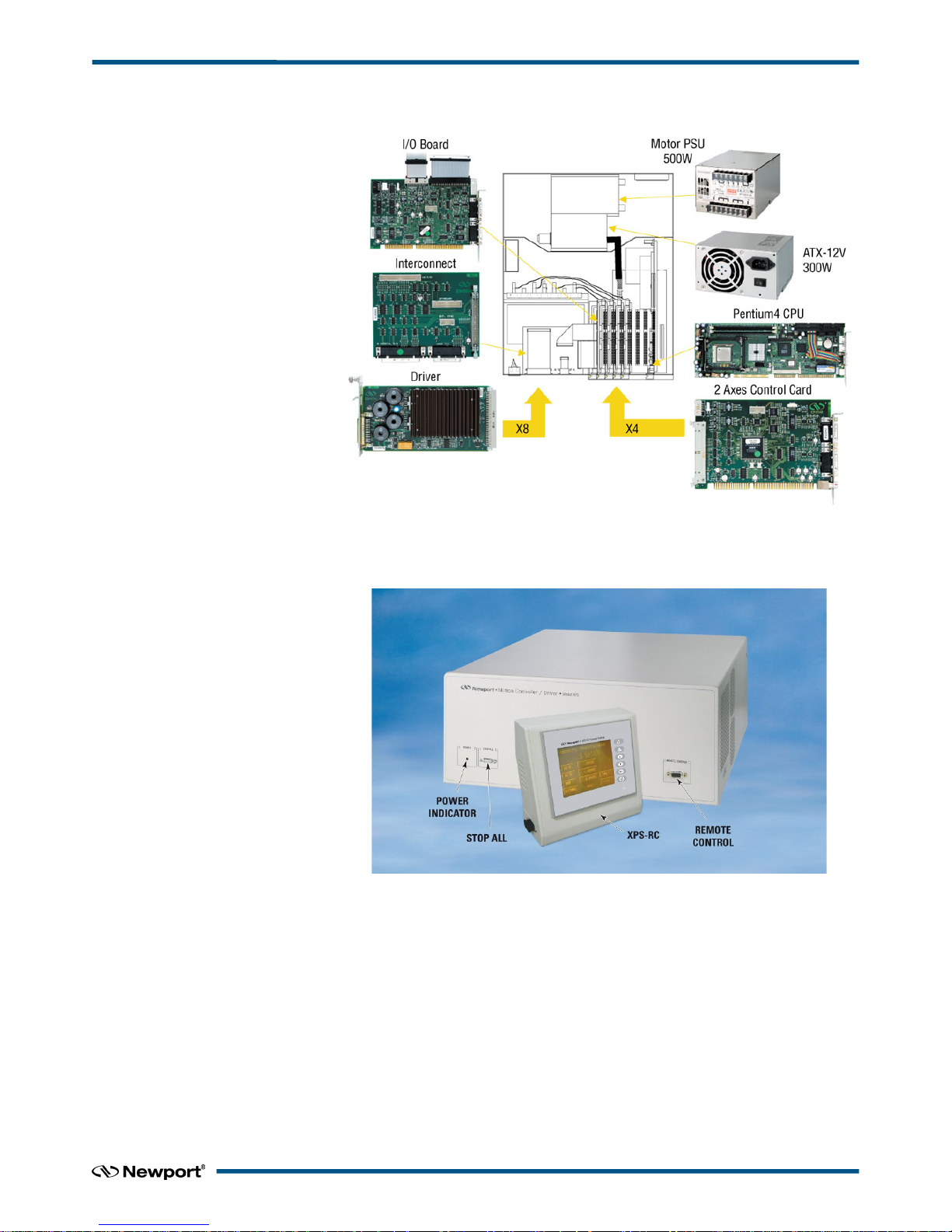
2.4 XPS Hardware Overview
Figure 6: XPS Hardware Overview.
2.5 Front Panel Description
Figure 7: Front Panel of XPS Controller/Driver.
The XPS-RC Remote Control plugs into the front panel of the XPS controller to enable
computer-independent motion and basic system diagnostics. For more information, refer
to the XPS data sheet and the XPS-RC manual.
9 XPSDocumentation V1.4.x (EDH0301En1060 — 10/17)
Page 22
XPS-Q8 Controller User’s Manual
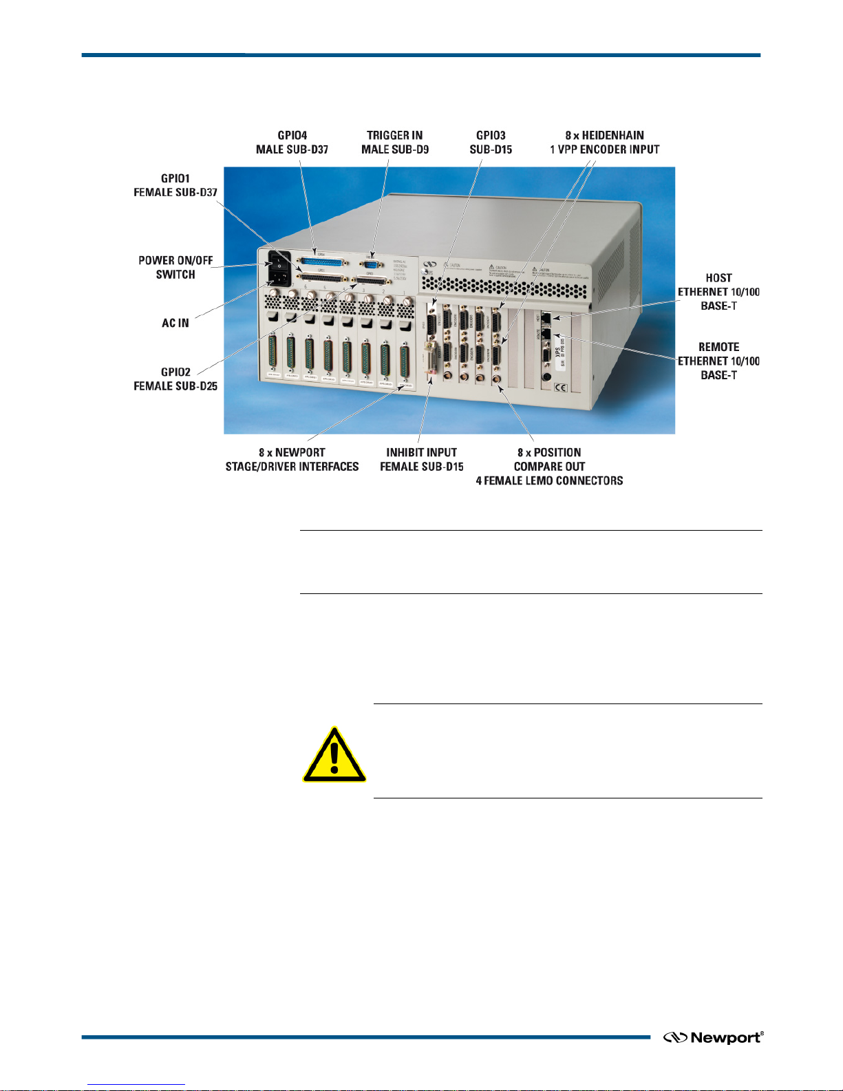
2.6 Rear Panel Description
Figure 8: Rear Panel of XPS Controller/Driver.
NOTE
The Main Power ON/OFF Switch is located above the inlet for the power cord. The
switch and the inlet must be accessible to the user.
2.6.1 Axis Connectors (AXIS 1 – AXIS 8)
Each installed axis driver card features a connector to attach a cable (supplied with
every Newport stage) between the controller and a motion device.
CAUTION
Carefully read the labels on the driver cards and make sure the
specifications (motor type, voltage, current, etc.) match those of the
motion devices you intend to connect. Severe damage could occur if a
stage is connected to the wrong driver card.
XPSDocumentation V1.4.x (EDH0301En1060 — 10/17) 10
Page 23
XPS-Q8 Controller User’s Manual
Figure 9: Axis Driver Card.
Please see the next section for installation instructions.
NOTE
Power Input: 100–240 V, 50–60 Hz, 11 A–5.5 A.
2.7 Ethernet Configuration
Figure 10: Ethernet Configuration.
2.7.1 Communication Protocols
The Ethernet connection provides a local area network through which information is
transferred in units known as packets. Communication protocols are necessary to dictate
how these packets are sent and received. The XPS Controller/Driver supports the
industry standard protocol TCP/IP.
TCP/IP is a “connection” protocol and in this protocol, the master must be connected to
the slave in order to begin communication. Each packet sent is acknowledged when
received. If no acknowledgment is received, the information is assumed lost and is
resent.
11 XPSDocumentation V1.4.x (EDH0301En1060 — 10/17)
Page 24
XPS-Q8 Controller User’s Manual
2.7.2 Addressing
There are two levels of addresses that define Ethernet devices. The first is the MAC
address. This is a unique and permanent 6 byte number. No other device will have the
same MAC address. The second level of addressing is the IP address. This is a 32-bit
(or 4 byte) number. The IP address is constrained by each local network and must be
assigned locally. Assigning an IP address to the controller can be done in a number of
ways (see section 3.5: “Connecting to the XPS“).
2.8 Sockets, Multitasking and Multi-user Applications
Based on the TCP/IP Internet communication protocol, the XPS controller has a high
number of virtual communication ports, known as sockets. To establish communication,
the user must first request a socket ID from the XPS controller server (listening at a
defined IP number and port number). When sending a function to a socket, the
controller will always reply with a completion or error message to the socket that has
requested the action.
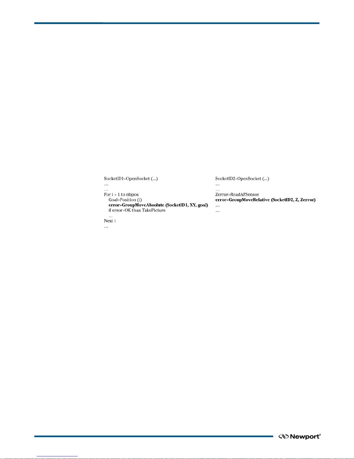
The concept and application of sockets has many advantages. First, users can split their
application into different segments that run independently on different threads or even
on different computers. To illustrate this, see below:
In this example, a thread on socket 1 commands an XY stage to move to certain
positions to take pictures while another thread on socket 2 independent of socket 1,
concurrently manages an auto-focusing system. The second task could even be run on a
different PC than the first task yet be simultaneously executed within the XPS.
Alternatively, if the auto-focusing system is providing an analog feedback, this task
could have been also implemented as a TCL script within the XPS (see the next topic).
Second, the concept of sockets has another practical advantage for many laboratory
users since the use of threads allows them to share the same controller for different
applications at the same time. With the XPS, it is possible that one group uses one axis
of the XPS controller for an optical delay line, while another group simultaneously uses
other axes for a totally different application. Both applications could run completely
independent from different workstations without any delays or cross-talk.
The XPS controller uses TCP/IP blocking sockets, which means that the commands to
the same socket are “blocked” until the XPS returns feedback about the completion of
the currently executed command (either '0' if the command has been completed
successfully, or an error code in case of an error). If customers want to run several
processes in parallel, users should open as many 84 parallel sockets. Please refer to
section 18.4: “Running Processes in Parallel“ for further information about sockets and
parallel processing.
2.9 Programming with TCL
TCL documentation is in a PDF file accessible from the XPS controller web site.
TCL stands for Tool Command Language and is an open-source string based command
language. With only a few fundamental constructs and relatively little syntax, it is very
easy to learn, yet it can be as powerful and functional as traditional C language. TCL
includes many different math expressions, control structures (if, for, foreach, switch,
etc.), events, lists, arrays, time and date manipulation, subroutines, string manipulation,
file management and much more. TCL is used worldwide with a user base approaching
XPSDocumentation V1.4.x (EDH0301En1060 — 10/17) 12
Page 25

XPS-Q8 Controller User’s Manual
one million users. It is quickly becoming a standard and critical component in thousands
of corporations. Consequently TCL is field proven, very well documented and has many
tutorials, applications, tools and books publicly available (www.tcl.tk).
XPS users can use TCL to write complete application code and the XPS allows them to
include any function in a TCL script. When developed, the TCL script can be executed
in real time in the background of the motion controller processor and does not impact
any processing requirements for servo updates or communication. The QNX hardware
real time multiprocessing operating system used on the XPS controller assures precise
management of the multiple processes with the highest reliability. Multiple TCL
programs run in a time-sharing mode with the same priority and will get interrupted
only by the servo, or communication tasks or when the maximum available time of 20
ms for each TCL program is over.
The advantage of executing application code within the controller over host run code is
faster execution and better synchronization, in many cases without any time taken from
the communication link. The complete communication link can be reserved for time
critical process interaction from or to the process or host controller.
NOTE
It is important to note that the XPS gives communication requests priority over
TCL script execution. When using TCL scripts for machine security or other time
critical tasks, it is therefore important to limit the frequency of continuous
communication requests from a host computer, which includes the XPS website,
and to verify the execution speed of repetitive TCL scripts.
13 XPSDocumentation V1.4.x (EDH0301En1060 — 10/17)
Page 26
XPS-Q8 Controller User’s Manual
3.0 Getting Started
3.1 Unpacking and Handling
It is recommended that the XPS Controller/Driver be unpacked in your lab or work site
rather than at the receiving dock. Unpack the system carefully; small parts and cables
are included with the equipment. Inspect the box carefully for loose parts before
disposing of the packaging. You are urged to save the packaging material in case you
need to ship your equipment.
3.2 Inspection for Damage
XPS Controller/Driver has been carefully packaged at the factory to minimize the
possibility of damage during shipping. Inspect the box for external signs of damage or
mishandling. Inspect the contents for damage. If there is visible damage to the
equipment upon receipt, inform the shipping company and Newport Corporation
immediately.
WARNING
Do not attempt to operate this equipment if there is evidence of
shipping damage or you suspect the unit is damaged. Damaged
equipment may present additional personnel hazard. Contact
Newport technical support for advice before attempting to plug in
and operate damaged equipment.
3.3 Packing List
Included with each XPS controller are the following items:
• User’s Manual and Motion Tutorial.
• XPS controller.
• Cross-over cable, gray, 3 meters.
• Straight-through cable, black, 5 meters.
• Power cord.
• Rack mount ears and handles.
If there are missing hardware or have questions about the hardware that were received,
please contact Newport.
CAUTION
Before operating the XPS controller, please read chapter 1.0 very
carefully.
3.4 System Setup
This section guides the user through the proper set-up of the motion control system. If
not already done, carefully unpack and visually inspect the controller and stages for any
damage. Place all components on a flat and clean surface.
CAUTION
No cables should be connected to the controller at this point!
First, the controller must be configured properly before stages can be connected.
XPSDocumentation V1.4.x (EDH0301En1060 — 10/17) 14
Page 27

XPS-Q8 Controller User’s Manual
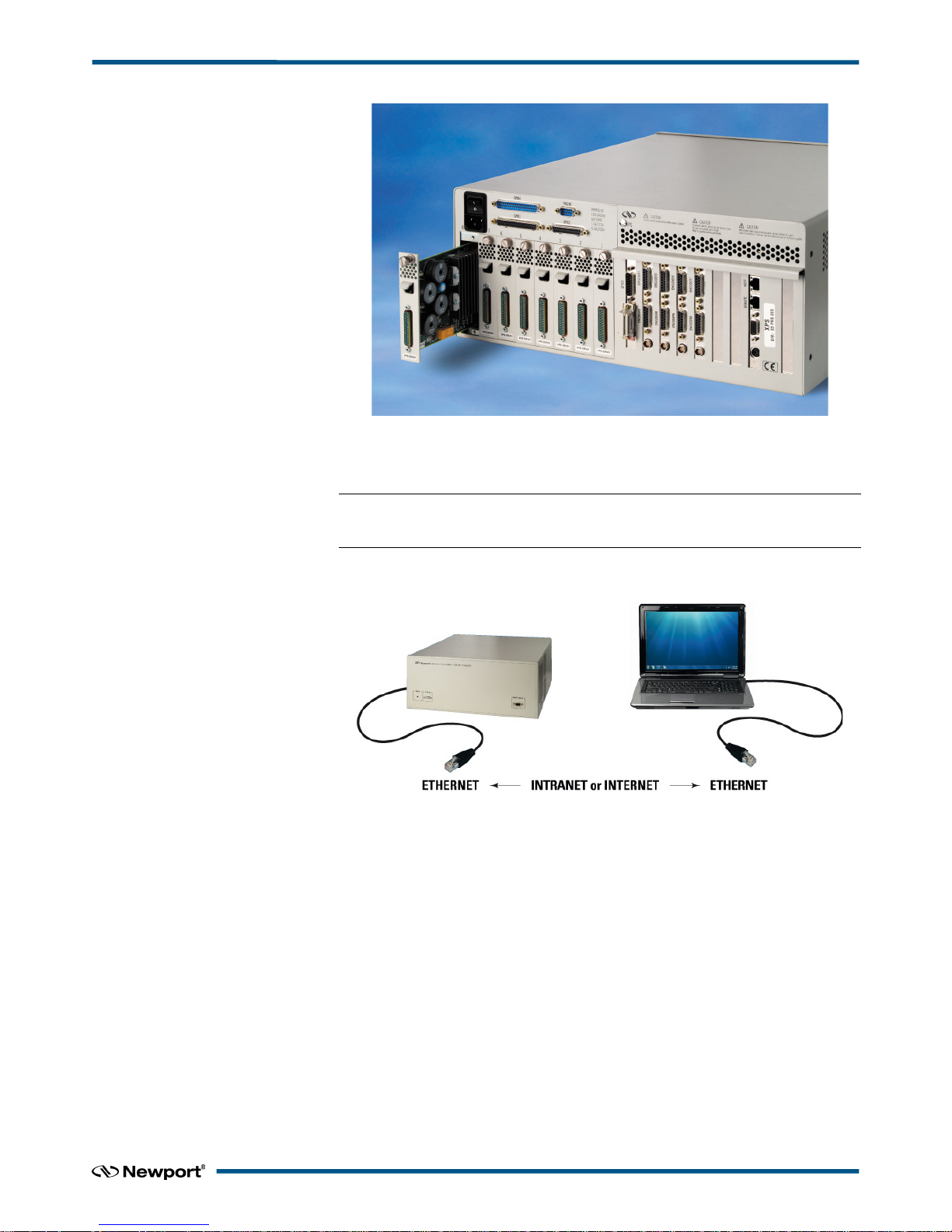
3.4.1 Installing Driver cards
Figure 11: Installing Driver cards.
Due to the high power of the XPS controller (300 W for the CPU and 500 W for the
drives), ventilation is very important.
To ensure a good level of heat dissipation, the following rules must be followed:
1. It is strictly forbidden to use the XPS controller without the cover properly mounted
on the chassis.
2. Driver boards must be inserted from right (driver 1) to left (driver 8) when looking
at the rear of the controller.
3. If less than eight are used, the remaining slots must be disabled with the appropriate
slot covers that were delivered with the controller.
4. The surrounding ventilation holes at the sides and back of the XPS rack must be free
from obstructions that prevent the free flow of air.
3.4.2 Power ON
• Plug the AC line cord supplied with the XPS into the AC power receptacle on the
rear panel.
• Plug the AC line cord into the AC wall-outlet. Turn the Main Power Switch to ON
(located on the Rear Panel).
• The system must be installed in such a way that power switch and power connector
are accessible by the user.
• After the main power is switched on, the LED on the front panel of the XPS will
turn green.
• There is an initial beep after power on and a second beep when the controller has
finished booting. If the controller boots properly, the second beep is happysounding, otherwise the sad-sounding beep is emitted. The time between the first
and the second beeps can be 12–18 seconds.
• There is also a STOP ALL button on the front panel that is used to stop any motion
in progress and then activate the inhibit input of all motor drivers. This is a software
function triggered by the inhibit input located on the rear panel or the STOP ALL
front panel button.
15 XPSDocumentation V1.4.x (EDH0301En1060 — 10/17)
Page 28
XPS-Q8 Controller User’s Manual
3.5 Connecting to the XPS
The Newport’s XPS Controller/Driver is a multi-axis motion controller system that is
based on a high performance 10/100 Base-T Ethernet connection using a CAT5 cable.
The controller can be connected in 2 different ways:
1. Direct connection-PC to XPS through a cross over cable (gray cable supplied).
2. Corporate Network connection – requires input from a Network Administrator
(black).
Two cables are provided with the motion controller:
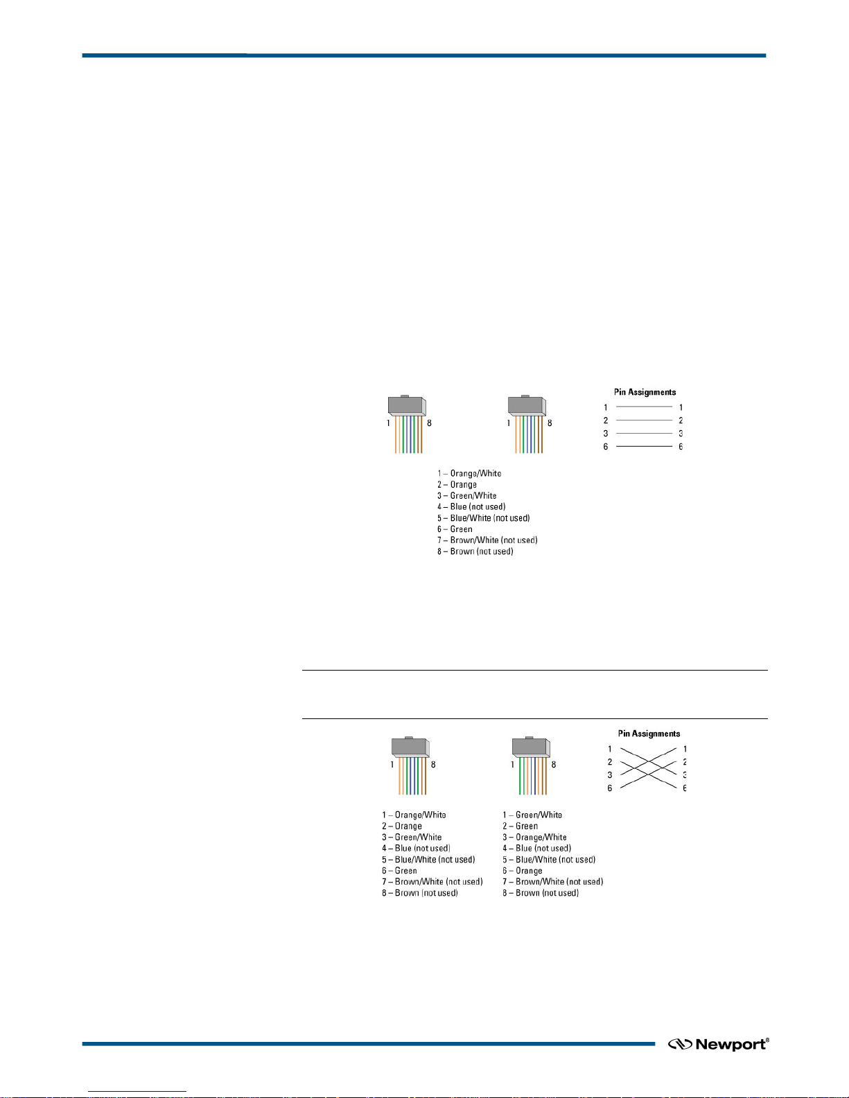
• Cross-over cable – used when connecting the XPS directly to a PC.
• Straight Ethernet cable – used when connecting the XPS through an intranet.
3.5.1 Straight through cables (black)
Standard Ethernet straight through cables are required when connecting the device to a
standard network hub or switch.
Figure 12: Straight through cables.
3.5.2 Cross-over cables (gray)
Standard Ethernet cross over cables are required when connecting the device directly to
the Ethernet port of a PC.
NOTE
Cross over cables are typically labeled (cross over or XO) at one or both ends.
Figure 13: Ethernet Cross Over Cables.
XPSDocumentation V1.4.x (EDH0301En1060 — 10/17) 16
Page 29
XPS-Q8 Controller User’s Manual
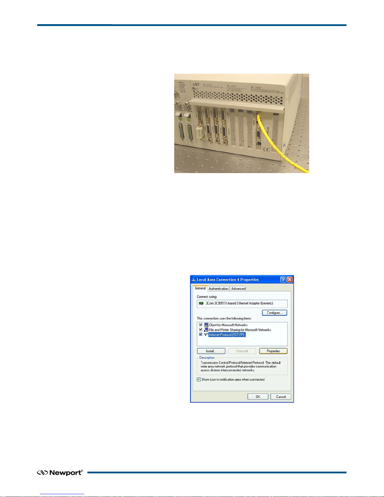
3.5.3 Direct Connection to the XPS Controller
For a direct connection between a PC and the XPS controller you need to use the
crossover cable and the HOST or REMOTE connector at the back of the XPS.
Figure 14: Direct Connection to the XPS using cross-over cable.
First, the IP address on the PC’s Ethernet card has to be set to match the default factory
XPS’s IP address 192.168.0.254 for the HOST connector or 192.168.254.254 for the
REMOTE connector.
Following is the procedure to set the Ethernet card address.
This procedure is for the Windows XP operating system (almost similar process
forWindow 7):
1. Start Button > Control Panel > Network Connections (Network and Sharing Center
=> Change adapter settings).
2. Right Click on Local Area Connection Icon and select Properties.
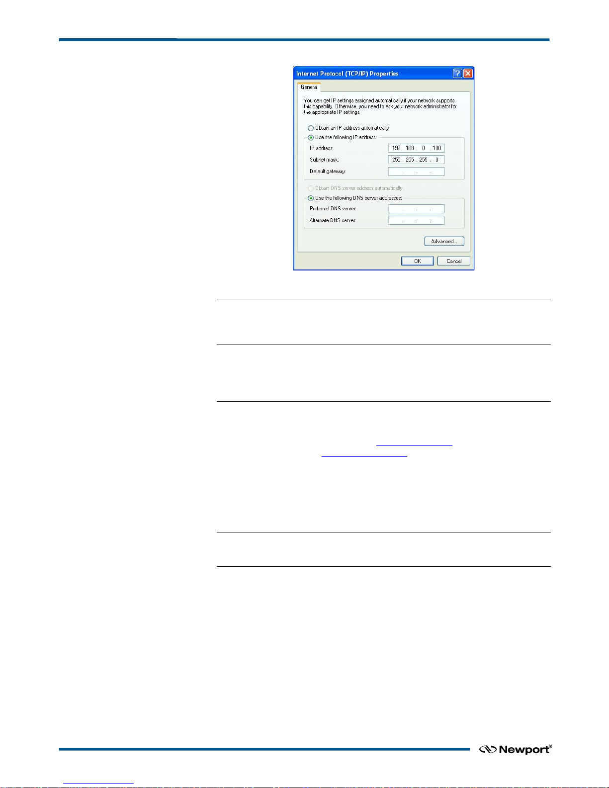
3. Highlight Internet Protocol (TCP/IP, TCP/IP4) and click on Properties.
4. In case using HOST connector type the IP address: 192.168.0.100 and Subnet Mask:
255.255.255.0.
In case using REMOTE connector type the IP address: 192.168.254.100 and Subnet
Mask: 255.255.255.0
17 XPSDocumentation V1.4.x (EDH0301En1060 — 10/17)
Page 30
XPS-Q8 Controller User’s Manual
5. Click “OK”.
NOTE
The The Last number of the IP address must be set to any number between 2 to
253: 100 for example.
NOTE
When configuring the controller to be on the network, the settings for the PC’s
Ethernet card will have to be set back to default under “Obtain an IP address
automatically”.
Once the Ethernet card address is set, you are ready to connect to the XPS controller.
Following is the procedure for connecting to the controller:
6. Open Internet Browser and connect to http://192.168.0.254
in case using HOST
connector or connect to http://192.168.254.254 in case using REMOTE connector
Login:
Name: Administrator
Password: Administrator (Please see the picture below).
Rights: Administrator
NOTE
Please note that the login text is case sensitive.
XPSDocumentation V1.4.x (EDH0301En1060 — 10/17) 18
Page 31

XPS-Q8 Controller User’s Manual
Once logged in, the XPS has established a direct connection to the local computer.
If you don’t want to connect the XPS controller through a Corporate Network you may
skip to section 3.7: “Connecting the Stages“.
NOTE
If you want to change the IP address of the XPS controller, follow the explanation
in the next section. It is necessary to keep using the gray cross-over Ethernet cable
to connect the XPS controller directly to the PC.
3.5.4 Connecting the XPS to a Corporate Network using Static IP Configuration
Once you are logged in using the previously described steps for direct connection, you
can change the IP configuration of the controller in order to connect the XPS over a
Network. Select “CONTROLLER CONFIGURATION” of the web-site and select the
sub-menu “IP Management”.
The static IP address, the subnet mask and the Gateway IP address must be provided by
your Network Administrator to avoid network conflicts. Once you have these addresses,
you can input them in the IP configuration window as shown above. The above shown
addresses are only examples.
19 XPSDocumentation V1.4.x (EDH0301En1060 — 10/17)
Page 32

XPS-Q8 Controller User’s Manual
NOTE
To avoid conflict with the REMOTE Ethernet plug, the IP address must be
different from 192.168.254…
NOTE
For the majority of Networks, the setting above for the Subnet Mask will work.
However, for larger networks (200 computers or more), the Subnet Mask address
must be verified with the IT department. In most cases and for larger networks,
the Subnet Mask is set to 255.255.0.0.
Once the appropriate addresses for the Static IP configuration are set, click on SET and
the following screen appears:
Go to the TERMINAL window, and double click on Reboot function, then press the
Execute button:
Wait for the end of the boot sequence. There is an initial beep a few seconds after power
on and a second beep when the controller has finished booting. The time between the
first beep and the second beep is approx. 12-18 seconds.
Connect the CAT-5 network cable (black) to the HOST connector of the XPS controller
and to your network.
After restarting the controller and restoring your PC’s Ethernet card default
configuration, open the Internet browser and connect using your given Static IP address.
If you don’t want to connect directly to the Corporate Network using the Dynamic IP
Configuration, skip to section 3.7: “Connecting the Stages“.
XPSDocumentation V1.4.x (EDH0301En1060 — 10/17) 20
Page 33

XPS-Q8 Controller User’s Manual
3.5.5 Configuring the XPS for Connection to a Corporate Network Using Dynamic IP
Configuration
It is recommended to ask your IT department to configure the XPS to your network to
avoid any issue with your network policies and rules.
• Configure your connection as described in §3.5.3 for REMOTE connection
• Connect the host plug to your network using a direct cable.
• Get to CONTROLLER CONFIGURATION=> IP management web page
• Select dynamic IP as shown below:
Click the SET button and the following screen appears:
Go to the TERMINAL window, double click on the Reboot function, then press the
Execute button:
21 XPSDocumentation V1.4.x (EDH0301En1060 — 10/17)
Page 34

XPS-Q8 Controller User’s Manual
Wait for controller to reboot, open the internet browser and connect to REMOTE
You can see the dynamic IP address in CONTROLLER CONFIGURATION =>
General
The IP address delivered by your DHCP is displayed above.
In case the XPS cannot negotiate an IP address from the DHCP the displayed address
will be 0.0.0.0. In that case contact your IT department.
XPSDocumentation V1.4.x (EDH0301En1060 — 10/17) 22
Page 35

XPS-Q8 Controller User’s Manual
Remove the REMOTE cable and, if needed, configure your PC back to its original
Ethernet configuration, you have saved before modification.
Make sure that the standard CAT-5 network cable (black) is connected to the HOST
connector of the XPS controller and to your network.
Open your internet browser and use the dynamic IP address.
Check with your IT department that the lease time set at the DHCP is longer than the
time you plan to leave the XPS switched off otherwise you will lose your dynamic
address and will need to connect to the REMOTE to know the new assigned one by the
DHCP.
NOTE
Do not use Dynamic IP configuration if your DHCP server uses Windows NT 4.0
23 XPSDocumentation V1.4.x (EDH0301En1060 — 10/17)
Page 36

XPS-Q8 Controller User’s Manual
3.5.6 Recovering a lost IP configuration
If you want to recover a lost IP configuration, you need to connect the PC directly to the
REMOTE connector at the back of the XPS with the gray cross-over cable.
Figure 15: Direct connection to the XPS
using a cross-over cable and the REMOTE connector.
First, the IP address on the PC’s Ethernet card must be set to match the fixed IP address
of the XPS in the REMOTE plug (192.168.254.254). Following is the procedure to set
the Ethernet card address.
This procedure is for the Windows XP operating system (almost similar process to
Windows 7):
1. Start Button > Control Panel > Network Connections (Network and Sharing).
2. Right Click on Local Area Connection Icon and select Properties.
3. Highlight Internet Protocol (TCP/IP, TCP/IP4) and click on Properties.
4. Type the following IP address and Subnet Mask as shown in the next figure.
XPSDocumentation V1.4.x (EDH0301En1060 — 10/17) 24
Page 37

XPS-Q8 Controller User’s Manual
5. Click “OK”.
NOTE
The last number of the IP address must be set to any number between 2 to 253:
100 in this example.
NOTE
When configuring the controller to be on the network, the settings for the PC’s
Ethernet card must be set back to default which is “Obtain an IP address
automatically”.
Once the Ethernet card address is set, you are ready to connect to the XPS controller.
Following is the procedure for connecting to the controller:
6. Open Internet Browser and connect to http://192.168.254.254
Login:
Name: Administrator
Password: Administrator (Please see the picture below).
Rights: Administrator
NOTE
Please note that the login text is case sensitive.
25 XPSDocumentation V1.4.x (EDH0301En1060 — 10/17)
Page 38

XPS-Q8 Controller User’s Manual
Once you are logged in, you can change the IP configuration by following the steps
described in section 3.5.4 or 3.5.5 depending on your configuration.
NOTE
If you want to reset the IP address to the default factory setting, follow the section
3.5.4
to set the IP address back to 192.168.0.254.
3.6 Testing your XPS-PC Connection and Communication
To check if the XPS communicates with to the host computer, send a ping message
from the computer to the XPS. This is done through the Windows menu: Start->Run->,
then type: ping + IP address of the XPS. See the example below for the IP address
192.168.33.236:
If the XPS is connected and communicates properly, it replies in the terminal window
that appears after clicking on the OK button:
XPSDocumentation V1.4.x (EDH0301En1060 — 10/17) 26
Page 39

XPS-Q8 Controller User’s Manual
If the XPS controller is not communicating, the window displays that the time delay of
the request is exceeded. Ensure that the correct cable and IP addresses are set properly.
3.7 Connecting the Stages
CAUTION
Never connect/disconnect stages while the XPS controller is powered
on.
CAUTION
Mount the stage(s) on a flat, stable surface before connecting to the
XPS controller.
With the power off, carefully connect the supplied cables to the stage and to the
appropriate axis connector at the rear of the controller. Secure both connections with the
locking thumbscrews.
When using stages with an analog encoder interface, a separate encoder cable must be
connected to the corresponding axis connector of the control board labeled “Encoder 1”
to “Encoder 8”.
Please note that the XPS controller will not detect cross-connection errors between the
motor of one stage and the encoder of another stage. Make sure that motor, encoder and
other cables are plugged to the appropriate axis driver card and encoder connectors.
CAUTION
It is strongly recommended that the user read section 3.4: “System
Setup
“ before attempting to turn the controller on. Serious damage
could occur if the system is not properly configured.
All Newport ESP-compatible stages are electrically and physically compatible with the
XPS controller. ESP-compatible stages are visually identified with a blue “ESP
Compatible” sticker on the stage. If an ESP-compatible motion system was purchased,
all necessary hardware to connect the stage with the XPS controller is included. The
stage connects to the XPS via a shielded custom cable that carries all the power and
control signals (encoder, limits, and home signals). The cable is terminated with a
standard 25-pin D-Sub connector.
“Dummy stages” might be used to simulate a stage. These allow users to configure and
test the system’s behavior without having real stages connected.
For a dummy stage, use a male 25-pin D-Sub connector with the signals for + and travel limits connected to ground, and plug this connector to the Newport stage interface
(see pinout description of the motor driver connectors in appendix F). Configure your
system with a number of these dummy stages. Dummy stages can be found in the
stages.ini file (see Admin/Config folder of the controller) under [DUMMY_STAGE].
27 XPSDocumentation V1.4.x (EDH0301En1060 — 10/17)
Page 40

XPS-Q8 Controller User’s Manual
3.8 Configuring the Controller
When the driver boards are installed and the IP address is configured, the controller can
be configured for the stages:
• Switch off the XPS controller.
• Connect the stages or motion devices.
• Switch on the XPS controller and wait for the end of the boot sequence. There is an
initial beep a few seconds after power on and a second beep when the controller has
finished booting. The time between the first beep and the second beep is approx. 1218 seconds.
• Open an internet browser and connect to http://<your fixed IP address>
Login: Administrator
Password: Administrator
Rights: Administrator
There are two possibilities to configure the controller: Auto configuration and manual
configuration. Auto Configuration is the simplest method to configure the controller,
but has some limitations:
• Auto configuration works only with Newport ESP compatible positioners.
• Auto configuration configures all detected positioners as single axis groups.
However, single axis groups provide limited functionality (no synchronized motion,
no trajectories, no XY or XYZ compensation). To take full benefit of the capabilities
of the XPS controller, a manual configuration is needed.
• For non-Newport stages or very old Newport stages, manual configuration is
required. See document ConfigurationWizard.pdf for details. This document is
accessible from the XPS web tools under the tab DOCUMENTATION.
• Manual configuration is also required for some vacuum compatible stages (no ESP
chip) and for stages with adjustable home position (-1, 0, +1), if the home position is
changed from the standard position 0 to -1 or +1. The positions +1 and -1 require
different settings in the stage data base, as the home switch position is not
recognized by the ESP chip.
XPSDocumentation V1.4.x (EDH0301En1060 — 10/17) 28
Page 41

XPS-Q8 Controller User’s Manual
3.8.1 Auto Configuration
When logged in as Administrator, select SYSTEM, then “Auto configuration”. The
following screen appears:
If you want to continue, click the "Yes, I confirm" button and the following page
appears:
Check, if all connected stages are recognized by the system. If yes, click “GENERATE
CONFIGURATION FILES”.
The controller reboots and the following screen appears (this may take up to 16
seconds):
Click “OK”.
When the controller has finished booting (a second beep after 12-18 seconds), press
“F5” to reload the page, select FRONT PANEL, and then select “Move”. The
following screen appears:
29 XPSDocumentation V1.4.x (EDH0301En1060 — 10/17)
Page 42

XPS-Q8 Controller User’s Manual
Click “Initialize”. The State number changes from 0 to 42 and the Action button
changes from “Initialize” to “Home”. Click “Home”. The stage starts moving to find its
reference position. When done, the state number is 11 and the action button changes to
disable. Enter an allowed position value in the “Abs move 1” field and click “Go”. The
stage moves to this absolute position.
Your system is now ready to use. For more advanced functions, please read the rest of
this manual.
NOTE
In “AUTO-CONFIGURATION” the default group is set as SingleAxis. To set the
positioners to a different group type, use manual configuration.
XPSDocumentation V1.4.x (EDH0301En1060 — 10/17) 30
Page 43

XPS-Q8 Controller User’s Manual
3.8.2 Manual Configuration for Newport Positioners
Manual configuration provides users access to all capabilities of the XPS controller.
For manual configuration, users first need to build the stage data base using the web
tool “Add from Database” under the main tab STAGE. When adding a new stage from
this web tool, the controller copies the parameters from its internal database (which
contains parameters for all Newport stages) and stores these parameters in a file called
stages.ini. Hence, the stages.ini file contains the parameters for only a subset of stages
as defined by the user. Users can assign any name for their stages. The default name is
the Newport part number, but in some cases it makes sense to use a different name. This
way, for instance, it is possible to add the same set of parameters several times in the
stage data base under different stage names. Later, you can modify certain parameters,
like travel ranges or PID settings, to optimize the stage for different applications.
All stage parameters can be modified using the Web Tool “Modify” under the main tab
STAGE. Alternatively, the stage parameters can be modified directly in the stages.ini
file using a text editor. The stages.ini file is located in the Config folder of the XPS
controller. This folder is accessible via ftp, see chapter 5 for details.
When all stages are added to the stages.ini file, build the system using the web tool
“Manual Configuration” under the main tab SYSTEM. In this tool, the stages get
assigned to positioners and the positioners get assigned to motion groups. Please refer to
chapter 6.3 for details on the different motion groups and their specific features. The
group name and positioner name can be any user given name. Once the system has been
built, all system information is stored in a file called system.ini. Also, the system.ini file
is located in the Config folder of the XPS controller.
The following describes the different steps needed to add a stage, to modify the stage
parameters and to build a manual configuration. Chapter 4.0 provides further
information about some of the steps described here.
Once you are logged in as Administrator, click on STAGE and then click on “Add
from database”.
1. The following screen appears:
2. Double click to select a family name from the list.
3. Double click to select the part number corresponding to your hardware.
31 XPSDocumentation V1.4.x (EDH0301En1060 — 10/17)
Page 44

XPS-Q8 Controller User’s Manual
4. Select the driver (corresponding to your hardware) and configuration.
For all continuous rotation stages, you can choose between a “regular” stage
configuration and a “Spindle” configuration. A Spindle is a specific rotary device
with a periodic position reset at 360° (by default), meaning 360° equals 0°. When
defining the stage as Spindle in the stages.ini, you must assign this stage also to a
Spindle group in the system configuration and vice versa. For details about Spindles,
please refer to section 6.3.
5. Once the stage name appears, you can modify it as needed(see comments above).
6. The box “Use ESP Compatibility for Hardware detection” is checked by default. If
your stage has an ESP chip inside (see the ESP-compatible sticker on the stage) this
box should remain checked. Otherwise, with vacuum compatible stages or with old
Newport stages, or with non-Newport stages, uncheck this box.
7. Click on “Add new stage” to add the stage.
Once all stages have been added, you can review or modify these parameters from
the screen “Modify” under the main tab STAGE.
NOTE
From this screen, you have access to all stage parameters. Only experienced
users should modify these parameters. For the exact meaning of the different
parameters, please refer to the document ConfigurationWizard.pdf, accessible
from the main tab DOCUMENTATION.
8. When finished with all stages, click on “Manual Configuration” under SYSTEM.
The following screen appears:
9. Enter a group name.
For example, if you are setting up two ILS stages, you can set them up as two Single
Axis groups, one XY group or one or two MulipleAxis groups. Any group name can
be given. In the example the name of the XY group is MyXYGroup.
10. Click on “ADD” to get to the next screen:
XPSDocumentation V1.4.x (EDH0301En1060 — 10/17) 32
Page 45

XPS-Q8 Controller User’s Manual
11. Enter the positioner names.
Any positioner name can be used. In this example the X positioner name is
ILS150CC_UPPER. The home sequence can be either “Together” or “X then Y”.
The other fields refer to the error compensation (mapping) of the XPS controller, see
chapter 10.0
for details. For the first configuration, don’t enter anything in these
fields.
12. Click on “VALID” to get following screen:
13. Enter the appropriate PlugNumber. The plug number is the axis number where the
stage is physically connected to the XPS controller. Looking at the rear of the
controller, plug number 1 is the first plug on the right and the number increases to
the left.
14. Select the StageName from the list of stages. These stage names refer to the stages
defined with the Web Tool “Stage Management”.
15. Specify the Time Flash Base Frequency value, the default is 40e
6
(must be between
39.5 e
6
and 40.5 e6 Hz).
16. Checking the box “Use a secondary Positioner” assigns a secondary positioner for a
gantry configuration. For details about gantries, please refer to section 4.9. Don’t
check this box for a regular XY group or for a regular SingleAxis group.
33 XPSDocumentation V1.4.x (EDH0301En1060 — 10/17)
Page 46

XPS-Q8 Controller User’s Manual
17. Click on “VALID” to return to the initial screen.
18. Continue the same way with the other motion groups.
19. When done, click on “Create new system.ini file” to complete the System
configuration. The controller re-boots and the following message appears:
Click on “OK”.
When the controller has finished booting (a second beep after 12-18 seconds), press
“F5” to reload the page, select FRONT PANEL, then select “Move”. The following
screen appears (Group names will be different according to your definition):
Click “Initialize”. The State number changes from 0 to 42 and the Action button
changes from “Initialize” to “Home”. Click “Home”. The stage starts moving to find its
reference position. When done, the state number is 11 and the action button is
“Disable”. Enter an allowed position value in the “Abs move 1” field and click “Go”.
The stage moves to this absolute position.
Your system is now ready to use. For more advanced functions, please read the rest of
this manual.
XPSDocumentation V1.4.x (EDH0301En1060 — 10/17) 34
Page 47

XPS-Q8 Controller User’s Manual
3.8.3 Manual Configuration for non Newport stages
For configuring the XPS controller to stages or positioning devices not made by
Newport, use the tool “Add Custom Stage” under the main tab STAGE. For detailed
information about this tool, please refer to the document ConfigurationWizard.pdf
provided under the main tab DOCUMENTATION.
3.9 System Shut-Down
To shut down the system entirely, perform the following procedure:
Wait for the stage(s) to complete their moves and come to a stop.
Turn off the power using the power switch located above the power cord at the back of
the controller.
35 XPSDocumentation V1.4.x (EDH0301En1060 — 10/17)
Page 48

XPS-Q8 Controller Software Tools
4.0 Software Tools
4.1 Software Tools Overview
The XPS software tools provide users a convenient access to the most common features
and functions of the XPS controller. All software tools are implemented as a web
interface. The advantage of a web interface is that it is independent from the user's
operating system and doesn't require any specific software on the host PC.
There are two options to log-in to the XPS controller: as “User” or as “Administrator”.
Users can log-in only with User rights. Administrators can log-in with User and with
Administrator rights. When logged-in with Administrator rights, you have an extended
set of tools available.
The predefined user has the log-in name Anonymous, Password Anonymous. The
predefined Administrator has the log-in name Administrator, Password
Administrator. Both the log-in name and the password are case sensitive.
Software Tools
XPSDocumentation V1.4.x (EDH0301En1060 — 10/17) 36
Page 49

XPS-Q8 Controller Software Tools
The main tab is displayed across the top of the XPS Motion Controller/Driver main
program window, and lists each primary interface option. Each interface option has its
own pull-down menu that allows the user to select various options by clicking the
mouse's left button.
On the following pages, a brief description of all available tools is provided.
Administrator Menus
Sub-Menu for CONTROLLER CONFIGURATION
Restricted set of User Menus
4.2 CONTROLLER CONFIGURATION – Users Management
This tool allows managing User accounts. There are two types of users: Administrators
and Users. Administrators have configurations rights. Users have restricted rights to use
the system.
The following steps are needed to create a new user:
1. Enter a new user name in the “login” field.
2. Choose the access rights: “User” or “Admin”.
3. Check the box “Reset PWD to XXXXXXXX”:
Your password is reset to XXXXXXXX.
4. Select the “VALID” button to add the new access account.
NOTE
The default password is XXXXXXXX and must be changed after the first log in.
37 XPSDocumentation V1.4.x (EDH0301En1060 — 10/17)
Page 50

XPS-Q8 Controller Software Tools
4.3 CONTROLLER CONFIGURATION – IP Management
See chapter 3.5 for details.
4.4 CONTROLLER CONFIGURATION – General
This screen provides valuable information about the firmware and the hardware of the
controller. It is an important screen for troubleshooting the controller.
XPSDocumentation V1.4.x (EDH0301En1060 — 10/17) 38
Page 51

XPS-Q8 Controller Software Tools
4.5 SYSTEM – Error file display
The Error File Display is another important screen for troubleshooting the XPS
controller. When the XPS encounters any error during booting, for instance due to an
error in the configuration files or because the configuration is not compatible with the
connected hardware, there are entries in the error log file that guides you to correct the
error.
When no error is detected during the system boot, this file is blank.
4.6 SYSTEM – Last error file display
The Last error file display shows errors encountered in the last XPS boot. When no
error is detected during the last system boot, this file is blank.
39 XPSDocumentation V1.4.x (EDH0301En1060 — 10/17)
Page 52

XPS-Q8 Controller Software Tools
4.7 SYSTEM – Auto Configuration
With the help of this screen, a quick, basic configuration of the XPS controller can be
done. Check/un-check those stage models that you want/don’t want the XPS controller
to configure to. When done, click “Generate Configuration Files”. The XPS controller
reboots. After re-booting, you are able to use the XPS controller in this basic
configuration. For further information, refer to chapter 3.8.1.
NOTE
“Generate Configuration Files” deletes your current system.ini configuration file.
For troubleshooting a system, make sure that you have a copy of the original
system.ini file for recovery.
Under Driver Model and Stage Model, all motor drivers and Newport ESP compatible
stages seen by the XPS controller are listed. This screen also provides valuable
information for diagnosing or troubleshooting the system.
4.8 SYSTEM – Manual Configuration
Manual Configuration allows you to review the current system configuration or to
define a new one. See also chapter 3.8.2 for further information.
To create a new system configuration, define all motion groups that should belong to
that system. It is not possible to append a motion group to an existing configuration
from this tool. To define a new motion group, do the following:
1. Enter the name of the new group (My_XY_Group in this case). Click on “ADD” to
confirm the new group.
XPSDocumentation V1.4.x (EDH0301En1060 — 10/17) 40
Page 53

XPS-Q8 Controller Software Tools
2. Enter the name for each positioner associated with the motion group (StepAxis and
ScanAxis in this case). Define the home sequence (“Together” or “XThenY” or
“YThenX”). For error compensation, define the name and structure of the correction
data, otherwise leave these fields blank. For details about error compensation, see
chapter 10.0
. When done, click on “VALID” to accept the configuration.
3. Specify the plug number. The plug number is the number of the drive card (1 to 8)
where the stage is physically connected to the XPS controller (see back of XPS
controller). Select the name of the Stage from the stage data base (scroll down
menu).
Checking the box “Use a secondary Positioner” assigns a secondary positioner for a
gantry configuration. A gantry is a motion device where two positioners, each of
them having a motor, an encoder, limits, etc., are used for a motion in one direction.
41 XPSDocumentation V1.4.x (EDH0301En1060 — 10/17)
Page 54

XPS-Q8 Controller Software Tools
Like most gantries, the two positioners are rigidly attached to each other. Hence, all
motions, including motor initialization, homing, and emergency stops must be done
in perfect synchronization. For details about Gantries and their configuration, please
refer to section 4.9.
Specify the Time Flash Base Frequency value, default is 40E6 (must be between
39.5E6 and 40.5E6 Hz).
When all positioners are configured, click on “VALID” to confirm the group
configuration.
4. When the configuration of each positioner is validated, the new group is listed in the
“New system build” window.
5. Do the same for all other motion groups. When done, click on “Generate config files
and Boot” to apply the new configuration.
XPSDocumentation V1.4.x (EDH0301En1060 — 10/17) 42
Page 55

XPS-Q8 Controller Software Tools
NOTE
“Generate config files and Boot” deletes the current system.ini file. To create a
copy of the current system.ini file, retrieve this from the “..admin\config” folder of
the XPS controller.
The following screen appears:
Click on “OK”.
6. When the controller has finished booting (second beep after 12-18 seconds), select
the SYSTEM tab, then “Error File Display”. When there is no entry in the error
file, your system is configured correctly and ready to use. If not, this file provides
some valuable information for troubleshooting; see also chapter 4.5.
This is an example of a system.ini file with one XY group and one Spindle group:
[GENERAL]
BootScriptFileName =
BootScriptArguments =
[GROUPS]
SingleAxisInUse =
SpindleInUse = Spin
XYInUse = My_XY_Group
XYZInUse =
MultipleAxesInUse =
[My_XY_Group]
PositionerInUse = StepAxis,ScanAxis
InitializationAndHomeSearchSequence = Together
;--- Mapping XY
XMappingFileName =
YMappingFileName =
[My_XY_Group.StepAxis]
PlugNumber = 3
StageName = VP-25XA-SECONDARY
[My_XY_Group.ScanAxis]
PlugNumber = 4
StageName = VP-25XA-PRIMARY
[Spin]
PositionerInUse = Rot
[Spin.Rot]
PlugNumber = 2
StageName = URS100CC_Spindle
43 XPSDocumentation V1.4.x (EDH0301En1060 — 10/17)
Page 56

XPS-Q8 Controller Software Tools
4.9 SYSTEM – Manual Configuration – Gantries (Secondary
Positioners)
This section is for experienced users of the XPS controller and addresses the
configuration of a gantry via a secondary positioner.
A gantry is a motion device where two positioners, each of them having a motor, an
encoder, limits, etc., are used for a motion in one direction. Like most gantries, the two
positioners are rigidly attached to each other, see example below. Hence, all motions,
including motor initialization, homing, and emergency stops must be done in perfect
synchronization.
Figure 16: Example of a gantry.
The XPS controller allows configuring single axis gantries (Xx configuration) and XY
gantries. For XY gantries, it is possible to define XxY, XYy and XxYy configurations.
Here, X and Y refer to the primary positioner and x and y to an assigned secondary
positioner.
To define a gantry, check the box “Use a secondary positioner” during the definition of
a Single Axis group or XY group. See chapter 4.8 for further instructions on how to
define a new motion group. When done, the following screen appears (example Single
Axis group):
XPSDocumentation V1.4.x (EDH0301En1060 — 10/17) 44
Page 57

XPS-Q8 Controller Software Tools
Define the plug number for the secondary positioner and the name from the stage data
base. The secondary positioner must have common values with the primary positioner
for the following parameters:
• MaximumVelocity
• MaximumAcceleration
• HomeSearchMaximumVelocity
• HomeSearchMaximumAcceleration
• MinimumTargetPosition
• MaximumTargetPositioner
The parameters “End referencing position” and “End referencing tolerance” refer to the
homing process of the gantry, see chapter 4.9.1 for details.
The parameter “Offset after initialization” is relevant only for gantries with linear
motors. See chapter 4.9.2 for details. For all other gantries, enter 0 for this parameter.
Furthermore, for certain XY gantries, it is also possible to apply a variable force ratio
for the two X positioners. This variable force ratio accounts for the different forces
required by the primary and the secondary X-axes positioners depending on the position
of the Y axis to ensure a torque-free motion. For details, see chapter 4.9.3.
NOTE
When using the gantry configuration, the secondary positioner is almost invisible
in the application. All functions are sent directly to the motion group or to the
(primary) positioner of that group. However, it is possible to get information about
the secondary positioner by data gathering and using “SecondaryPositioner” as
the positioner name. Example:
MySingleGantry.S1.SecondaryPositioner.FollowingError
For further details about data gathering, see chapter 12.0.
4.9.1 Home search of gantries
During the home search of a gantry, first, the secondary positioner is homed and the
primary positioner follows the motion. Then, the primary positioner is homed and the
secondary positioner follows the motion. At the end, the primary positioner is at its
home position, but the secondary positioner will be off its home position due to the
tolerances in the assembly of the gantry. This "ideal" position can be defined to be the
position of best orthogonality between the X and Y axis of the gantry. The parameter
“End referencing position” defines the “ideal” position of the secondary positioner
when the primary positioner is at its home position. The parameter “End referencing
tolerance” defines the maximum allowed distance from the secondary positioner’s ideal
position, when the primary positioner is at its home position.
When the actual distance is greater than the value of the “End referencing tolerance”,
homing is aborted. When the actual distance is less than the value for the “End
referencing tolerance”, then the secondary positioner moves to the “End referencing
position” while the primary positioner stays at its home position. Hence, this parameter
corrects the angle between the gantry's X and Y axes.
45 XPSDocumentation V1.4.x (EDH0301En1060 — 10/17)
Page 58

XPS-Q8 Controller Software Tools
The sketch below illustrates this process:
1) Search home of the Secondary positioner. The primary positioner follows
2) Search home of the Primary positioner. The secondary positioner follows.
3) If the distance of the secondary positioner’s position to the “End referencing
position” is greater than the value for the “End referencing tolerance”, homing is
aborted. If not, the Secondary positioner moves to the “End referencing position”
while the primary positioner stays at its home position.
The index difference refers to the difference of the secondary positioner’s position when
the primary positioner is at its home position to the home position of the secondary
positioner. The value for the Index difference can be queried by the function
PositionersEncoderIndexDifferenceGet().
When no other metrology tools are available, the following method can be used to
determine a value for the “End referencing position” of an assembled gantry:
Set the value for “End referencing position” and “End referencing tolerance” to 0.
Complete the configuration of your system. After reboot, initialize and home the gantry
group. With high probability, the homing will fail with error -85 due to the zero value
for the “End referencing tolerance”. Query the index difference with the function
PositionersEncoderIndexDifferenceGet(). Repeat the initialization, homing and
querying of the index difference several times and build the average and the standard
deviation from all values. Now, configure a new system with the same gantry. For “End
referencing position”, apply the average value of the index difference. For “End
referencing tolerance”, apply a value that is approximately equal to 6 times of the
standard deviation of the index difference. Complete your configuration and reboot your
system. Initialize and home the gantry group several times to confirm the gantry is
working properly.
4.9.2 Gantries with linear motors
The parameter “Offset after initialization” defines the offset of magnetic tracks of the
linear motors between the primary and the secondary positioners. This parameter is
important to optimize the performance of a gantry with linear motors. It ensures the
correct sinusoidal commutation of the two motor signals. An accurate measurement of
the offset can be done only with dedicated metrology tools.
For gantries NOT driven in acceleration mode, e.g. gantries with NO linear motors, this
value is set to 0.
Also, for stages driven in acceleration mode and are configured for gantries, it is
recommended to “force the initialization position” using the LMI mode (Large Move
Initialization). To do so, append LMI to the line
MotorDriverInterface=AnalogSinXAccelerationLMI (X = 60, 90 or 120) and add a line
InitializationCycleDuration=5 at the end of the section with driver command interface
parameters in the stages.ini. Example:
Secondary
1 2 Pos = 0
Pos = 0
Pos = End referencing Position
Pos = Index difference
3
Initial position
Primary
XPSDocumentation V1.4.x (EDH0301En1060 — 10/17) 46
Page 59

XPS-Q8 Controller Software Tools
;--- Driver command interface parameters
MotorDriverInterface=AnalogSin120AccelerationLMI
ScalingAcceleration=30641;--- units / s²
AccelerationLimit=27856;--- units / s²
MagneticTrackPeriod=24;--- units
InitializationAccelerationLevel=20;--- percent
InitializationCycleDuration=5;--- seconds
With the LMI setting, during initialization, the motor is energized and the stage moves
to the closest stable magnetic position. The result is a quick motion of the stage at most
by half of the length of the magnetic track. This behavior might be undesired, but
provides a more failure proof method for initialization than the default initialization
process, which applies only very small oscillations to the stage during initialization.
4.9.3 Gantries with linear motors and variable force ratio
For XY gantries, where the two X-axes are driven by linear motors (meaning driven in
acceleration mode), it is also possible to apply a variable force ratio for the two X axes
positioners. This variable force ratio accounts for the different forces required by the
primary and the secondary X-axes positioner depending on the position of the Y axis.
When correctly set, it ensures a torque-free acceleration and deceleration of the X-axis,
see picture below for illustration.
To apply a variable load ratio to an XY gantry, check the box “Use a force ratio” during
the group definition. See example below. There are three parameters to input:
• Y Offset for force ratio
• Primary Y Motor Force Ratio
• Secondary Y Motor Force Ratio
A correct definition of these three parameters is not simple. For additional information
about this function, please call Newport.
47 XPSDocumentation V1.4.x (EDH0301En1060 — 10/17)
Page 60

XPS-Q8 Controller Software Tools
This is an example of a system.ini file with one XY gantry:
[GROUPS]
SingleAxisInUse =
SpindleInUse =
XYInUse = MyXYGantry
XYZInUse =
MultipleAxesInUse =
[MyXYGantry]
PositionerInUse = X, Y
InitializationAndHomeSearchSequence = YThenX
XMappingFileName =
YMappingFileName =
;--- Gantry Force Ratio parameters
YOffsetForForceRatio = 0
PrimaryYForceRatio = 0
SecondaryYForceRatio = 0
[MyXYGantry.X]
PlugNumber = 1
StageName = IMS600LM
;---- Secondary positioner (X2)
SecondaryPlugNumber = 4
SecondaryStageName = IMS600LM
SecondaryPositionerGantryEndReferencingPosition = 10.2243
SecondaryPositionerGantryEndReferencingTolerance = 0.1
SecondaryPositionerGantryOffsetAfterInitialization = 7.47
[MyXYGantry.Y]
PlugNumber = 3
StageName = IMS400LM
XPSDocumentation V1.4.x (EDH0301En1060 — 10/17) 48
Page 61

XPS-Q8 Controller Software Tools
4.10 STAGE – Add from Data Base
With the help of this screen, a stage from the Newport stage data base can be added to
the personal stage data base, called stages.ini. In the lower left corner, you can review
the name of the stages that are already in this stage data base. To add a new stage, do
the following:
1. Double click to select a family name from the list.
2. Double click to select the part number corresponding to your hardware.
3. Select the driver (corresponding to your hardware) and group configuration.
For all continuous rotation stages, you can choose between a “regular” stage
configuration and a “Spindle” configuration. A Spindle is a specific rotary device
with a periodic position reset at 360°, meaning 360° equals 0°. When defining the
stage as Spindle in the stages.ini, you must assign this stage also to a Spindle group
in the system configuration and vice versa. For details about Spindles, please refer
also to section 6.3.
4. Once the stage name appears, it can be modified. The default name is the Newport
part number, but in some cases it makes sense to use a different name. This way, for
instance, it is possible to add the same set of parameters several times in the stage
data base under different stage names. Later, modifying certain parameters, like
travel ranges or PID settings, to optimize the stage for different applications
becomes straightforward.
5. The box “Use ESP Compatibility for Hardware detection” is checked by default. If
the stage has an ESP chip (a blue ESP-compatible sticker is on the stage) this box
shall remain checked. Otherwise, with vacuum compatible stages or with old
Newport stages, uncheck this box.
6. Click on “Add new stage” to add a stage.
49 XPSDocumentation V1.4.x (EDH0301En1060 — 10/17)
Page 62

XPS-Q8 Controller Software Tools
4.11 STAGE – Modify
This screen allows you to review and modify all parameters of stages included in the
stages.ini. Only experienced users should modify these parameters. For the exact
meaning of the different parameters, please refer to the document
ConfigurationWizard.pdf, accessible from the main tab DOCUMENTATION.
XPSDocumentation V1.4.x (EDH0301En1060 — 10/17) 50
Page 63

XPS-Q8 Controller Software Tools
To modify the parameters of a stage, do the following:
1. Select a stage from the list. Click on “Modify”.
2. Scroll down to the section that contains the parameters that will be modified.
Parameters that require quite common changes, are the minimum and the maximum
target positions of a rotation stage. For example, to enable larger rotations of a
rotation stage that is not configured as a Spindle, set the maximum target position to
a very high value and the minimum target position to a very low value. In this case it
is also required to disable the limit switches of the rotation stage, see stage manual
for details.
3. When done, click "Save" to apply the new values, or click “Cancel”
if a mistake was
made.
4. To take the new values into account, reboot the controller or use “Restart
Application” button.
The same screen allows duplicating stages in the stages.ini (in most case some
parameters are modified as a second step) or to delete stages from the stages.ini.
51 XPSDocumentation V1.4.x (EDH0301En1060 — 10/17)
Page 64

XPS-Q8 Controller Software Tools
4.12 FRONT PANEL – Move
The Move page provides access to basic group functions like initialize, home, or motor
disable, and executes relative and absolute moves.
The Move page also provides a convenient review of all important group information
like group names, group states and positions. All motion groups are listed in the Move
page.
NOTE
A spindle group can do relative moves and absolute moves. So it can be used in the
Move page. See section 4.14 for more information about Spindle moves.
FRONTPANEL Menu Move Submenu
Positioner name
Positioner position
Kill All groups
Positioner
Velocity
Absolute
Position
Move to the absolute
position
Move to the relative
position
Relative
Position
XPSDocumentation V1.4.x (EDH0301En1060 — 10/17) 52
Page 65

XPS-Q8 Controller Software Tools
4.13 FRONT PANEL – Jog
The Jog page allows executing a jog motion. A jog motion is a continuous motion,
where only the speed and acceleration are defined, but no target position. Speed and
acceleration can be changed during the motion (but not during the acceleration period).
For a Jog motion, the jog mode must be enabled, see “Action” button.
4.14 FRONT PANEL – Spindle
The Spindle page provides similar functions to the Jog page. However, specific jog
actions are replaced by spindle actions that only work for Spindle groups.
53 XPSDocumentation V1.4.x (EDH0301En1060 — 10/17)
Page 66

XPS-Q8 Controller Software Tools
4.15 FRONT PANEL – I/O View
The I/O View page shows the current states or values of all analog and all digital I/O’s
of the controller. To set the outputs, use the page I/O Set.
4.16 FRONT PANEL – I/O Set
The I/O Set page allows setting the analog and digital outputs of the controller.
XPSDocumentation V1.4.x (EDH0301En1060 — 10/17) 54
Page 67

XPS-Q8 Controller Software Tools
4.17 FRONT PANEL – Positioner Errors
The Positioner Errors page is an important page for trouble-shooting. When
encountering any problems during the use of the system, information about the errors
related to the positioners are found in this page. Hovering the cursor over the letters
brings up the type of error.
Note that all positioner errors encountered since the last “Clear all positioner errors” are
displayed, even if some of the errors may no longer be present. The “Refresh” button
refreshes the error page. This means that new errors will be displayed while retaining a
history of previous errors..
To clear the errors, use the button “Clear all positioner errors”.
4.18 FRONT PANEL – Hardware Status
The Hardware Status page is another important page for trouble-shooting, but not all
information is related to an error.
55 XPSDocumentation V1.4.x (EDH0301En1060 — 10/17)
Page 68

XPS-Q8 Controller Software Tools
4.19 FRONT PANEL – Driver Status
The Driver Status page is another important page for trouble-shooting, but not all
information is related to an error.
The type of status information that you can get depends on the drivers used.
4.20 TERMINAL
The Terminal screen allows the execution of all XPS controller functions. It also
provides a convenient method for generating executable TCL scripts. For more details
about TCL scripts, see chapter 18.1.
To execute a function from the Terminal, do the following:
1. Double click to select a function, which then appears in the "API to execute"
window.
2. Define the arguments for the function.
For functions with dynamic arguments “ADD” and “REMOVE” buttons are
available. Alternatively, you can use a “,” as a separator between different
arguments.
XPSDocumentation V1.4.x (EDH0301En1060 — 10/17) 56
Page 69

XPS-Q8 Controller Software Tools
For some arguments like ExtendedEventName, ExtendedActionName or
GatheringType, the argument name is not directly accessible. In these cases, define
the first part of the argument name, then click in the field again and define the
second part of the argument name. See the example below for defining the
GatheringType with the function GatheringConfigurationSet():
57 XPSDocumentation V1.4.x (EDH0301En1060 — 10/17)
Page 70

XPS-Q8 Controller Software Tools
3. When all arguments are defined, click “OK”. Now review the final syntax of the
function and make final text changes, as needed. When done, click “Execute”.
4. When the function is executed, the controller’s response will appear in the Received
message window. A returned 0 means that the function has been executed
successfully. In all other cases, there will be an error code. Use the function
ErrorStringGet() to get more information about the error.
The functions are listed in alphabetical order. Only those functions that are listed are
available from the current system configuration. For example, if the system consists
only of SingleAxis groups, no group specific functions for Spindles, XY groups, XYZ
groups or MultipleAxis groups will be listed.
XPSDocumentation V1.4.x (EDH0301En1060 — 10/17) 58
Page 71

XPS-Q8 Controller Software Tools
4.21 TUNING – Auto-Scaling
Auto-scaling is only available with positioners that feature a direct drive motor such as
the XM, ILS-LM, IMS-LM or RGV100BL. To guarantee consistent performance of
these stages, it is strongly recommended to perform Auto-scaling once the load is
attached to the stage. During auto-scaling, the XPS controller measures the mass (inertia
with rotation stages) on the positioner and returns recommended values for the Scaling
Acceleration parameter.
Repeat Auto-scaling with any major change of the payload on the positioner. With no
major change of the payload, there is no need to redo Auto-scaling.
To perform Auto-scaling, do the following:
1. Select the main tab TUNING. Then select a positioner name. The following screen
appears:
2. Click “Kill group”, then click “Auto-scaling”. The stage vibrates for a couple of
seconds. Then, the following message appears:
3. To save the recommended values, click “Save”. To apply these new values, reboot
the controller. The positioner should now work properly.
59 XPSDocumentation V1.4.x (EDH0301En1060 — 10/17)
Page 72

XPS-Q8 Controller Software Tools
NOTE
All other functions of the tuning page should be used only by experienced users.
4.22 TUNING – Auto-Tuning
NOTE
Apart from the Auto-scaling feature, which is described in the previous chapter,
only experienced motion control users should use the TUNING tool of the XPS
controller.
All Newport positioners are supplied with default tuning parameters that provide
consistently high performance for the vast majority of applications. Use the
Tuning tool with Newport positioners only when not fully satisfied with the
dynamic behavior of the positioners. Auto-Tuning works best with direct drive
stages. Friction drive or ballscrew drive systems may not result in optimum tuning
using this feature.
The following is a brief description of the TUNING tool:
1. Select a positioner name. The following screen appears:
XPSDocumentation V1.4.x (EDH0301En1060 — 10/17) 60
Page 73

XPS-Q8 Controller Software Tools
2. Perform a data gathering with your current parameter settings.
1. Initialize and home the positioner, then move to the desired start position.
2. Define the gathering data: For the stage tuning, it is recommended to gather only
the following error and the current position.
3. Define a typical motion distance.
4. Define the frequency divisor. The frequency divisor defines the sampling rate of
the gathering. A frequency divisor equal to one means one data point is gathered
every servo cycle, or every 125 µs. With most positioners, it is sufficient to set a
value of 10, meaning one data point every 1.25 ms.
5. Define the number of points in relation to the distance, the frequency divisor, the
velocity and the acceleration.
6. Define the velocity, acceleration and jerk time.
7. When done, click “Set & Move”.
3. The gathering results are displayed in a Java applet window. To view the results,
install Java™ Runtime Environment Standard Edition on the host or remote
computer. The XPS has a direct link to download Java™ Runtime when not
installed on the computer.
4. When satisfied with the results, there is no need to tune the stage. If not satisfied,
return to the tuning page and move back to the start position.
5. Next to the Auto-tuning button, there is a Mode field for Auto-tuning. Select “Short
settling” or “High robustness”. Choose “Short settling” to improve the settling time
after a motion or to reduce the following error during the motion. Short settling will
define “high” PID vales for your stage, but there is a risk of oscillation. Choose
61 XPSDocumentation V1.4.x (EDH0301En1060 — 10/17)
Page 74

XPS-Q8 Controller Software Tools
“High robustness” to improve the robustness of the motion system and to avoid
oscillations during or after a motion. “High robustness”, for instance, can avoid
oscillations for a rotation stage with high payload inertia. When done with the
selection, click Auto-tuning.
6. The stage vibrates for a couple of seconds. When done the following screen appears:
7. Press “Set” to apply the new parameters. “Set” only changes the working parameters
during data gathering. Recover the previous parameters by rebooting the system.
8. To test the behavior of the motion system with the new parameters, repeat the same
data gathering and compare the results. Make manual changes to the settings and
verify the behavior.
9. To permanently save the settings to the stages.ini, press “Save”. “Save” overwrites
the current settings in your stages.ini. Press “Save” only when fully satisfied with the
results. For recovery, Newport recommends making a copy of the stages.ini with the
old settings.
NOTE
For further information about the meaning of the different tuning parameters, see
chapter 14.0
.
XPSDocumentation V1.4.x (EDH0301En1060 — 10/17) 62
Page 75

XPS-Q8 Controller Software Tools
4.23 FUNCTIONAL TESTS
The FUNCTIONAL TESTS page allows running TCL scripts saved in the
“/Admin/Public/Scripts/ FunctionalTests” folder of the XPS controller. Supplied in the
firmware, the Functional Tests scripts will then display the results of a gathering file.
Select the TCL Script name then press “Execute script” to run the script or “Kill script”
to stop its execution.
4.24 FTP (File Transfer Protocol) Connection
FTP is the protocol for exchanging files over the Internet. It works in the same way as
HTTP for transferring web pages from a server to a user's browser and SMTP for
transferring electronic mail across the Internet. FTP uses the Internet TCP/IP protocol to
enable data transfer.
An FTP connection is needed to view the information saved in the XPS controller, to
download documentation, to transfer configuration files (to modify them locally), to
transfer TCL scripts, etc…
To connect to the FTP server:
• Start the XPS controller and wait until the boot sequence completes.
• Open an Internet browser window. Windows explorer is another option to access the
files.
• Connect to the FTP server with the IP address of the controller:
Example
• Select “File” from the menu of the Internet browser, and then “Connect as…”. The
following window appears:
63 XPSDocumentation V1.4.x (EDH0301En1060 — 10/17)
Page 76

XPS-Q8 Controller Software Tools
Specify the user name and password. Press log on. The folders of the XPS controller are
displayed (see below). Browse through the different folders and transfer data from or to
your host PC the same way as Windows Explorer.
XPSDocumentation V1.4.x (EDH0301En1060 — 10/17) 64
Page 77

XPS-Q8 Controller Software Tools
5.0 Maintenance and Service
5.1 Enclosure Cleaning
The XPS Controller/Driver should only be cleaned with a sufficient amount of soapy
water solution. Do not use an acetone or alcohol solution, this will damage the finish of
the enclosure.
5.2 Obtaining Service
The XPS Controller/Driver contains no user serviceable parts. To obtain information
regarding factory service, contact Newport Corporation or your Newport representative
and be ready with the following information:
• Instrument model number (on front panel) and original order number.
• Instrument serial number (on rear panel).
• Description of the problem.
If the XPS is to be returned to Newport Corporation, a Return Number will be issued,
which should be referenced in the shipping documents.
Complete a copy of the Service Form found at the end of this User’s Manual and
include it with your shipment.
5.3 Troubleshooting
For troubleshooting, the user can query different error and status information from the
controller. The XPS controller provides the Positioner Error, the Positioner Hardware
Status, the Positioner Driver Status, the Group Status, and also a general system error.
If there is an error during command execution, the controller will return an error code.
The command ErrorStringGet can be used to retrieve the description corresponding to
the error code.
The following function commands are used to retrieve Positioner Error and Positioner
Hardware Status:
• PositionerErrorGet: Returns an error code.
• PositionerErrorStringGet: Returns the description of the error code.
• PositionerHardwareStatusGet: Returns the status code.
• PositionerHardwareStatusStringGet: Returns the description corresponding to the
status code.
In a fault condition, it is also very important to know the current status of the group and
the cause of the transition from the previous group status to the current group state. The
following functions can be used to retrieve the Group Status:
• GroupStatusGet: Returns the group status code.
• GroupStatusStringGet: Returns the description corresponding to the group status
code.
NOTE
Refer to the Programmer’s Manual for a complete list of status and error codes.
Also refer to chapter 4.0
for troubleshooting the XPS controller with the help of its
web utilities.
65 XPSDocumentation V1.4.x (EDH0301En1060 — 10/17)
Page 78

XPS-Q8 Controller Software Tools
5.4 Updating the Firmware Version of Your XPS Controller
Users can regularly update the controller with new firmware releases. Updating the
firmware does not overwrite the stages.ini or system.ini. No configuration will be lost
when updating the firmware. Refer to the FirmwareHistory document which explains
the changes needed in the stages.ini and system.ini files.
Refer to the XPS page at www.newport.com for more information.
A history file for the firmware and the stage database is added to the XPS web
documentation.
XPSDocumentation V1.4.x (EDH0301En1060 — 10/17) 66
Page 79

XPS-Q8 Controller Motion Tutorial
6.0 XPS Architecture
6.1 Introduction
The architecture of the XPS firmware is based on an object-oriented approach. Objects
are key to understanding this approach. Real-world objects share two characteristics:
state and behavior. Software objects are modeled after real-world objects, so they have
state and behavior too. A software object maintains its state in one or more variables. A
variable is an item of data named by an identifier. A software object implements its
behavior with methods. A method is a function (subroutine) associated with an object.
Therefore, an object is a software bundle of variables and related methods.
Encapsulating related variables and methods into a neat software bundle is a simple yet
powerful idea that provides two primary benefits to software developers:
• Modularity: The source code for an object can be written and maintained
independent of the source code for other objects. Also, an object can be easily
passed around in the system.
• Hidden information: An object has a public interface that other objects can use to
communicate with it. The object can maintain private information and methods that
can be changed at any time without affecting the other objects that depend on it.
All objects have a life cycle and state diagrams are used to show the life cycle of the
objects. The transition from one state to another is initiated after receiving a message
from another object. Like all other diagrams, state diagrams can be nested in different
layers to keep them simple and easy to read.
Motion Tutorial
67 XPSDocumentation V1.4.x (EDH0301En1060 — 10/17)
Page 80

XPS-Q8 Controller Motion Tutorial
6.2 State Diagrams
State diagrams are a way to describe the behavior of each group or object. They
represent each steady state of a group and every transition between states in an
exhaustive way. State diagrams contain the following components:
Here is an example of a simple stage diagram:
State diagrams can also include sub state diagrams:
The state diagrams that are specific to the XPS controller follow the same format.
Within the XPS controller, all positioners are assigned to different motion groups.
These motion groups have the following common state diagram:
XPSDocumentation V1.4.x (EDH0301En1060 — 10/17) 68
Page 81

XPS-Q8 Controller Motion Tutorial
As shown in the above state diagram, all groups have to be first initialized and then
homed before any group is ready to perform any other function. Once the group is
homed, it is in a ready state. There are five different motion groups available with the
XPS controller:
• SingleAxis group
• Spindle group
• XY group
• XYZ group
• MultipleAxes group
Each group also has group specific states. Please refer to the Programmer’s Manual for
group-specific state diagrams for the five different groups.
All positioners of a group are bundled together for security handling. Security handling
of different groups is treated independently. Following is a list of the different faults and
consequences that can happen in the XPS controller:
Error type
Consequence
General inhibition
Motor fault
Encoder fault
Emergency stop
End of travel
Emergency brake
Following error
Motion disable
• After an emergency brake or an emergency stop, both considered major faults, the
corresponding group goes to a “not initialized” state: the system has to be initialized
and homed again before any further motion.
• After a following error, as it is considered a minor fault, the corresponding group
goes to a “Disable” state: a GroupMotionEnable() command puts the system back
into “ready” state.
At any given time the group status can be queried from the controller. The function
GroupStatusGet (GroupName) returns the current state number. The state numbers
correspond to the state and to the event that generated the transition (if any). The
function GroupStatusStringGet (StateNumber) returns the state description
corresponding to the state number.
69 XPSDocumentation V1.4.x (EDH0301En1060 — 10/17)
Page 82

XPS-Q8 Controller Motion Tutorial
Called function
1. GroupInitialize
2. GroupHomeSearch
3. GroupMoveAbsolute
4. GroupMoveRelative
5. GroupMotionDisable
6. GroupMotionEnable
7. GroupMoveAbort
8. GroupKill or KillAll
9. GroupSpinParametersSet
10. GroupSpinModeStop
11. SpinSlaveModeEnable
12. SpinSlaveModeDisable
13. GroupAnalogTrackingModeEnable
14. GroupAnalogTrackingModeDisable
15. GroupInitializeWithEncoderCalibration
16. GroupReferencingStart
17. GroupReferencingStop
State diagram of the XPS controller.
6.3 Motion Groups
Within the XPS controller, each positioner or axis of motion must be assigned to a
motion group. This “group” can either be a SingleAxis group, a Spindle group, an XY
group, an XYZ group or a MultipleAxes group. Once defined, the XPS automatically
manages all safeties and trajectories of the motion group from the same function. For
instance, the function GroupHomeSearch (GroupName) automatically homes the
whole motion group GroupName independent of its definition as a SingleAxis group, a
Spindle group, an XY group, an XYZ group or a MultipleAxes group. Within the
system configuration file, system.ini, select the home sequence as “sequential”, one
positioner after the other, or in “parallel”, with all positioners homing at the same time.
With a single function such as GroupMoveAbsolute (GroupName, Position), the
whole motion group, GroupName, is moved synchronously to the defined absolute
position, where “Position” may be one or more parameters depending on the number of
positioners this motion group contains. This same command can be used to move a
single positioner of a group to an absolute position by using the syntax
GroupMoveAbsolute (GroupName.PositionerName, Position1). These powerful,
object-oriented functions are not only extremely intuitive and easy to use, they are also
more consistent with other programming methods and reduce the number of commands
learned compared to traditional mnemonic commands.
Another benefit provided by motion groups is improved error handling. For instance,
whenever an error occurs due to a following error or a loss of the end-of-run signal,
only the motion group where the error originated is affected (disabled) while all other
motion groups remain active and enabled. The XPS manages these events
automatically. This greatly reduces complexity and improves the security and safety of
sensitive applications.
XPSDocumentation V1.4.x (EDH0301En1060 — 10/17) 70
Page 83

XPS-Q8 Controller Motion Tutorial
To illustrate this, let’s consider a typical scanning application. If there is an error on the
stepping axis of the XY table (which is set-up as an XY group), only the XY table is
disabled while the auto-focusing tool (a vertical stage that is defined as a separate
SingleAxis group) continues to function.
Each of the five available motion groups has specific features:
6.3.1 Specific SingleAxis Group Features
Master-Slave – To enable this function, the slaved positioner must be defined as a
SingleAxis group. The master positioner can be a member of any motion group. So it is
possible to define a Positioner as a slave of another positioner that is part of an XYZ
group.
6.3.2 Specific Spindle Group Features
The Spindle Group is a single positioner group that enables continuous rotations with no
limits and with a periodic position reset.
Master-Slave - In Master-Slave spindle mode the master and the slave group must be
Spindle groups.
6.3.3 Specific XY Group Features
Line-Arc trajectories, XY mapping – These features are only available with XY groups.
It is not possible for an XY group to perform a Spline or a PVT trajectory. Also, an XY
group cannot be slaved to another group, however, any positioner of an XY group can
be a master to a slaved SingleAxis group.
6.3.4 Specific XYZ Group Features
Spline trajectories, XYZ mapping – These features are only available with XYZ groups.
It is not possible for an XYZ group to perform a Line-Arc or a PVT trajectory. Also, an
XYZ group cannot be slaved to another group, however, any positioner of an XYZ
group can be a master to a slaved SingleAxis group.
6.3.5 Specific MultipleAxes Features
PVT trajectories – PVT trajectories are only available with MultipleAxes groups. It is
not possible for a MutipleAxes group to perform a Line-Arc or a Spline trajectory. Also,
a MultipleAxes group cannot be slaved to another group. However, any positioner of a
MultipleAxes group can be a master to a slaved SingleAxis group.
6.4 Native Units
The XPS controller supports user-defined native units like µm, inches, degrees or
arcsecs. The units for each positioner are set in the configuration file where the
parameter EncoderResolution indicates the number of units per encoder count. When
using the XPS controller with Newport stages, this part of the configuration is done
automatically. Once defined, all motions, speeds and accelerations can be commanded
in the same native unit without any math needed. All other parameters like stage travel,
maximum speed and all compensations are defined on the same scale as well. This is a
great advantage compared to other controllers that can be commanded only in multiples
of encoder counts, which can be an odd number.
In the XPS controller there are 4 types of position information for each positioner:
TargetPosition, SetpointPosition, FollowingError and CurrentPosition. These are
described as follows:
The CurrentPosition is the current physical position of the positioner. It is equal to the
encoder position after all compensations (backlash, linear error and mapping) have been
taken into account.
The SetpointPosition is the theoretical position commanded to the servo loop. It is the
position where the positioner should be, during and after the end of the move.
71 XPSDocumentation V1.4.x (EDH0301En1060 — 10/17)
Page 84

XPS-Q8 Controller Motion Tutorial
The FollowingError is the difference between the CurrentPosition and the
SetpointPosition.
The TargetPosition is the position where the positioner must be after the completion of
a move.
When the controller receives a new motion command after the previous move is
completed, a new TargetPosition is calculated.
This new target is received as an argument for absolute moves. For relative moves, the
argument is the length of the move and the new target is calculated as the addition of the
current target and the move length. Then the profiler of the XPS calculates a set of
SetpointPositions to determine where the positioner should be at each given time.
When the positioner is controlled by a digital servo loop with a PID corrector, part of
the signals sent to the motor of the positioner is a function of the following error. Part of
this function is the integral gain of the PID filter that requires a following error equal to
zero to reach a constant value.
The encoder in the positioner delivers a discrete signal (encoder counts). Take the
example of an encoder with a resolution of 1 and a target position equal to 1.4. The real
position cannot reach the value of the target position (1 or 2 instead of 1.4), so the
following error will never be equal to zero (closest values are +0.6 and -0.4). Thus, due
to the integral gain of the PID filter, the system will never settle, but will oscillate
between the positions 1 and 2.
The XPS controller avoids this instability while allowing the use of native units instead
of encoder counts by using a rounded value of the TargetPosition to calculate the
motion profile and a rounded value for the following error. But the non-rounded value
of the TargetPostion will be stored as final position, so that there is no accumulation of
errors due to rounding, in case of successive relative moves.
To understand the difference, consider a positioner with a resolution of 1 that is at the
position 0. This positioner receives a relative motion command of 10.4. At the end of
the motion the CurrentPosition will be 10 and the SetpointPosition will be 10, but the
TargetPosition will be 10.4. The positioner then receives the same relative motion
command again. At the end of this motion the CurrentPosition will be 21, the
SetpointPosition will be 21 and the TargetPosition will be 20.8.
NOTE
When an application requires a sequence of small incremental motion of constant
step size close to the encoder resolution, make sure that the commanded
incremental motion is equal to a multiple of encoder steps.
The TargetPosition, SetpointPosition, CurrentPositon and FollowingError can be
queried from the controller using the appropriate function calls.
XPSDocumentation V1.4.x (EDH0301En1060 — 10/17) 72
Page 85

XPS-Q8 Controller Motion Tutorial
7.0 Motion
7.1 Motion Profiles
Motion commands refer to strings sent to a motion controller that will initiate a motion.
The XPS controller provides several modes of positioning from simple point-to-point
motion to the most complex trajectories. On execution of a motion command, the
positioner moves from the current position to the desired destination. The exact
trajectory for the motion is calculated by a motion profiler. So the motion profiler
defines where each of the positioners should be at each point in time. There are details
worth mentioning about the motion profiler in the XPS controller:
In a classical trapezoidal motion profiler (trapezoidal velocity profile), the acceleration
is an abrupt change. This sudden change in acceleration can cause mechanical
resonance in a dynamic system. In order to eliminate the high frequency portion of the
excitation spectrum generated by a conventional trapezoidal velocity motion profile, the
XPS controller uses a sophisticated SGamma motion profile. Figure 17 shows the
acceleration, velocity and position plot for the SGamma profile.
Figure 17: SGamma Motion Profile.
The SGamma motion profile provides better control of dynamic systems. It allows for
perfect control of the excitation spectrum that a move generates. In a multi-axes system
this profile gives better control of each axis independently, but also allows control of the
cross-coupling that are induced by the combined motion of the axes. As shown in figure
17, the acceleration plot is parabolic. The parabola is controlled by the jerk time (jerk
being the derivative of the acceleration). This parabolic characteristic of the acceleration
73 XPSDocumentation V1.4.x (EDH0301En1060 — 10/17)
Page 86

XPS-Q8 Controller Motion Tutorial
results in a much smoother motion. The jerk time defines the time needed to reach the
necessary acceleration. One feature of the XPS controller is that it automatically adapts
the jerk time to the step width by defining a minimum and a maximum jerk time. This
auto-adaptation of the jerk time allows a perfect adjustment of the system’s behavior
with different motion step sizes.
NOTE
Because of jerk-controlled acceleration, any move has a duration of at least four
times the jerk time.
For the XPS controller, the following parameters need to be configured for the SGamma
profile:
• MaximumVelocity (units/s)
• MaximumAcceleration (units/s
2
)
• EmergencyDecelerationMultiplier (Applies to Emergency Stop)
• MinimumJerkTime (s)
• MaximumJerkTime (s)
The above parameters are set in the stages.ini file for a positioner. When using the XPS
controller with Newport stages, these parameters are automatically set during the
configuration of the system.
The velocity, acceleration and jerk time parameters is modified by the function
PositionerSGammaParametersSet().
Example
PositionerSGammaParametersSet (MyGroup.MyStage, 10, 80, 0.02, 0.02)
This function sets the positioner “MyStage” velocity to 10 units/s, acceleration to 80
units/s
2
and minimum and maximum jerk time to 0.02 seconds. The set velocity and
acceleration must be less than the maximum values set in the stages.ini file. These
parameters are not saved if the controller is shut down. After a re-boot of the controller,
the parameters will retain the values set in the stages.ini file.
In actual use, the XPS places a priority on the displacement position value over the
velocity value. To reach the exact position, the speed of the positioner may vary slightly
from the value set in the stages.ini file or by the PositionerSGammaParametersSet
function. So the drawback of the SGamma profile is that the velocity used during the
move can be a little bit different from the velocity defined in the parameters. For
example, the exact velocity will change when the move distance is changed, move
100mm, then 100.001 mm then 100.011 mm. There will be some changes to the
commanded velocity. This change can be ignored for many applications except where
an accurate time synchronization during the motion is required.
The function, PositionerSGammaExactVelocityAdjustedDisplacementGet(), can be
used as described below to achieve the exact desired speed in applications that require
an accurate value of the velocity during a move. In this case, the velocity value is
adhered to, but the target position may be slightly different from the one required. In
other words, according to the application requirements, the user can choose between
very accurate positions or very accurate velocities.
Example
PositionerSGammaExactVelocityAdjustedDisplacementGet
(MyGroup.MyStage, 50.55, ExactDisplacement)
This function returns the exact displacement for that move with the exact
constant velocity set shown in the example above (10 mm/s). The result is
stored in the variable ExactDisplacement, for instance 50.552.
GroupMoveAbsolute (MyGroup.MyStage, 50.552)
XPSDocumentation V1.4.x (EDH0301En1060 — 10/17) 74
Page 87

XPS-Q8 Controller Motion Tutorial
In the above example, for a position of 50.55 mm, the command returns a value of
50.552. This means that in order for the positioner “MyStage” to achieve the desired
velocity in the most accurate way, the commanded position should be 50.552 mm
instead of 50.55 mm.
The XPS can report two different positions. The first one is the SetpointPosition or
theoretical position. This is the position where the stage should be according to the
profile generator.
The second position is the CurrentPosition. This is the actual position as reported by the
positioner’s encoder after taking into account all compensation. The relationship
between the SetpointPosition and the CurrentPosition is as follows:
Following error = SetpointPosition - CurrentPosition
The functions to query the SetpointPosition and the CurrentPosition values are:
GroupPositionCurrentGet() and GroupPositionSetpointGet()
7.2 Home Search
Home search is a specific motion process. Its goal is to define a reference point along
the course of travel accurately and repeatably. The need for this absolute reference point
is twofold. First, in many applications, it is important to know the exact position in
space, even after a power-off cycle. Secondly, to prevent the motion device from hitting
a travel obstruction set by the application (or its own hardware travel limits), the
controller uses software limits. To be efficient, the software limits must be referenced
accurately to the home before running the application.
After motor initialization, any motion group must first be homed or referenced before
any further motion can be executed. Here, homing refers to a predefined motion process
that moves a stage to a unique reference position and defines this as Home. Referencing
refers to a group state that allows the execution of different motions and the setting of
the position counters to any value (see next section for details). The referencing state
provides flexibility for the definition of custom home search and system recovery
processes. It should only be used by experienced users.
A number of hardware solutions may be used to determine the position of a motion
device, the most common are incremental encoders. By definition, these encoders can
only measure relative position changes and not absolute positions. The controller keeps
track of position changes by incrementing or decrementing a dedicated counter
according to the information received from the encoder. Since there is no absolute
position information, position “zero” is where the controller was powered on (and the
position counter was reset).
To determine an absolute position from incremental encoders, the controller must use a
reference position that is unique to the entire travel, called a home switch or origin
switch, usually in conjunction with an index pulse.
An important requirement is that this switch must have the same resolution as the
encoder pulses.
If the motion device uses a linear scale as a position encoder, the home switch is usually
placed on the same scale and read with the same resolution.
If, on the other hand, a rotary encoder is used, homing becomes more complicated. To
have the same resolution, a mark on the encoder disk could be used (called index pulse),
but because the mark repeats every revolution, it does not define a unique point over the
entire travel. An origin switch, on the other hand, placed in the travel of the motion
device is unique, but typically is not precise or repeatable enough. The solution is to use
both in a dedicated search algorithm as follows.
Figure 18: Home (Origin) Switch and Encoder Index Pulse.
75 XPSDocumentation V1.4.x (EDH0301En1060 — 10/17)
Page 88

XPS-Q8 Controller Motion Tutorial
A Home switch (Figure 18) separates the entire travel in two areas: one has a high level
and the other has a low level. The most important part is the transition between the two
areas. Just by looking at the origin switch level, the controller knows already on which
side of the transition the positioner is and which direction to start the homing process.
The task of the home search process is to define one unique index pulse as the absolute
position reference. This is first done by finding the home switch transition and then the
very first index pulse (Figure 19).
Figure 19: Slow-Speed Origin Switch Search.
Labeling the two motion segments D and E, the controller searches for the origin switch
transition in D and for the index pulse in E. To guarantee the best repeatability possible,
both D and E segments must perform at a very low speed and without stopping in
between.
The homing process described above has a drawback. At low search speeds, the process
could take a very long time if the positioner happens to start from the one end of travel.
To speed things up, the positioner is moved fast until it is in the vicinity of the origin
switch and then performs the two slow motions, D and E, at half the home search
velocity. The new sequence is shown in Figure 20.
Figure 20: High/Low-Speed Home (Origin) Switch Search.
Motion segment B is performed at the pre-programmed home search speed. When the
home switch transition is encountered, the motion device stops (with an overshoot),
reverses direction and searches for the switch transition again, this time at half the speed
(segment C). Once the switch transition is encountered, it stops again with an overshoot,
reverses direction and executes D and E with one tenth of the programmed home search
speed.
In the case when the positioner starts from the other end of the home switch transition,
the routine is shown in Figure 21.
Figure 21: Home (Origin) Search from Opposite Direction.
The positioner moves at the home speed up to the home switch transition (segment A)
and then executes segments B, C, D and E as in figure 20.
XPSDocumentation V1.4.x (EDH0301En1060 — 10/17) 76
Page 89

XPS-Q8 Controller Motion Tutorial
This home search process guarantees that the last segment, E, is always performed in
the positive direction of travel and at the same reduced speed. This method ensures an
precise and repeatable reference position.
There are 7 different home search processes available in the XPS controller:
1. MechnicalZeroAndIndexHomeSearch is used when the positioner has a hardware
home switch plus a zero index from the encoder. This process is the default for most
Newport standard stages.
2. MechanicalZeroHomeSearch is used with positioners that have a hardware home
switch but with no zero index from the encoder.
3. IndexHomeSearch is used with positioners that have a home index, but with no
hardware home switch signal. In this process, the positioner initially moves in the
positive direction to find the index. When a + limit switch is detected, the direction
of motion reverses until the index is found.
Note
For users with CIE03 (E3425x) boards, if a limit is detected before the index,
there will be an emergency brake and the group will go in NOT_INITIALIZED
status.
4. CurrentPositionAsHome is used when the positioner has no home switch or index.
This process will keep the positioner’s home at its current location. Setting the home
too close to the EOR could generate unwanted emergency stops. Start with around
50 MIM (Minimum Incremental Movement) units, but an optimum distance may be
determined by trial and error, depending on the stage.
This feature can also be used to set home arbitrarily and bypass a home switch.
5. MinusEndOfRunAndIndexHomeSearch uses the positioner’s minus end-of-run
limit as a hardware home switch and a zero index from the encoder. This process is
comparable to MechanicalZeroAndIndexHomeSearch, but uses the minus end-ofrun limit signal as hardware home switch and moves in the positive direction until
the Index is reached. Otherwise, it will reach the positive limit or a timeout will
occur. The positioner homes to a position that is different from the
MechanicalZeroAndIndexHomeSearch location.
6. MinusEndOfRunHomeSearch uses the positioner’s minus end-of-run limit for
homing. Note that the emergency stop at the negative limit is disabled during
homing.
7. PlusEndOfRunHomeSearch uses the positioner’s plus end-of-run limit for homing
and the emergency stop at the positive limit is disabled during homing.
Note
This home search works only with the CIE05 (E3920x) board or later versions.
The home search process is set up in the stages.ini file. When using the XPS controller
with Newport ESP-compatible stages, this setting is done automatically with the
configuration of the system. The home search velocity, acceleration and time-out are
also set up in the stages.ini file.
Each motion group can either be homed “together” or “sequentially”, meaning all
positioners belonging to that group home at the same time in parallel or all the
positioners home one after the other, respectively. This option is also set up in the
system.ini file or during configuration.
A Home search can be executed with all motion groups and any motion group MUST
be homed before any further motion can be executed. To home a motion group that is in
a “ready” state, that motion group must first be “killed” and then “re-initialized”.
77 XPSDocumentation V1.4.x (EDH0301En1060 — 10/17)
Page 90

XPS-Q8 Controller Motion Tutorial
Example
This is the sequence of functions that initialize and home a motion group.
GroupInitialize (MyGroup)
GroupHomeSearch (MyGroup)
…
GroupKill (MyGroup)
7.3 Referencing State
The predefined home search processes described in the previous section might not be
compatible with all motion devices or might not be always executable. For instance, if
there is a risk of collision during a standard home search process. In other situations, a
home search process might not be desirable. For example, to ensure that the stages have
not moved, the current positions are stored into memory. In this case, it is sufficient to
reinitialize the system by setting the position counters to the stored position values.
For these special situations, the XPS controller’s referencing state as in alternative to
the predefined home search processes.
NOTE
The Referencing state should be only used by experienced users. Incorrect use
could cause equipment damage.
The Referencing state is a parallel state to the homing state, see the state diagram on
page 81, Figure 22. To enter the referencing state, send the function
GroupReferencingStart(GroupName) while the group is in the NOT REFERENCED
state.
In the Referencing state, the function
GroupReferencingActionExecute(PositionerName, Action, Sensor, Parameter) will
perform certain actions like moves, position latches of reference signal transitions, or
position resets. The function
PositionerSGammaParametersSet(PositionerName) can be used to change the
velocity, acceleration and jerk time parameters.
To leave the referencing state, send the function
GroupReferencingStop(GroupName). The Group will then be in the HOMED state,
state number 11.
The syntax and function of the function
GroupReferencingActionExecute(PositionerName, Action, Sensor, Parameter) will
be discussed in detail. With this function, there are four parameters to specify:
• PositionerName is the name of the positioner on which this function is executed.
• Action is the type of action that is executed. There are eight actions that can be
distinguished into three categories: Moves that stop on a sensor event, moves of
certain displacement, and position counter reset categories.
• Sensor is the sensor used for those actions that stop on a sensor event. It can be
MechanicalZero, MinusEndOfRun, or None.
• Parameter is either a position or velocity value and provides further input to the
function.
XPSDocumentation V1.4.x (EDH0301En1060 — 10/17) 78
Page 91

XPS-Q8 Controller Motion Tutorial
The following table summarizes all possible configurations:
Sensor Parameter
Action MechanicalZero MinusEndOfRun None Position Velocity
LatchOnLowToHighTransition
LatchOnHighToLowTransition
LatchOnIndex
LatchOnIndexAfterSensorHighToLowTransition
SetPosition
SetPositionToHomePreset
MoveToPreviouslyLatchedPosition
MoveRelative
7.3.1 Move on sensor events
The “move on sensor events” starts a motion at a defined velocity, latches the position
when a state transition of a certain sensor is detected, then stops the motion. There are
four possible actions under this category:
• LatchOnLowToHighTransition
• LatchOnHighToLowTransition
• LatchOnIndex
• LatchOnIndexAfterSensorHighToLow
With LatchOnLowToHighTransition and LatchOnHighToLowTransition, latching
happens when the right transition on the defined sensor occurs. The sensor can be
latched to either MechanicalZero, MinusEndOfRun and PositiveEndOfRun when
supported by the hardware, refer to §7.2 to know which hardware supports the function.
With LatchOnIndex and LatchOnIndexAfterSensorHighToLow, latching happens
on the index signal. With LatchOnIndexAfterSensorHighToLow, latching happens
on the first index after a high to low transition at the defined sensor (MechanicalZero
or MinusEndOfRun). Because of the dedicated hardware circuits used for the position
latch, there is essentially no latency between sensor transition detection and position
acquisition.
In all cases, motion stops after the latch. However, this means that the stopped position
doesn’t rest on the sensor transition, but at some short distance from it. To move exactly
to the position of the sensor transition, use the action
MoveToPreviouslyLatchedPosition.
The latch does not change the current position value. In order to set the current position
value, use the action SetPosition or SetPositionToHomePreset, for instance, after a
MoveToPreviouslyLatchedPosition.
In the Referencing state, the limit switch safeties (emergency stop) are still enabled until
the MinusEndOfRun sensor is specified with a GroupReferencingActionExecute()
function. When specified, the limit switch safeties are disabled and will only be reenabled with the function GroupReferencingStop().
The Parameter has a sign, if it is assigned as velocity (floating point). This means that
the direction of motion is dictated by the sign of the velocity parameter.
79 XPSDocumentation V1.4.x (EDH0301En1060 — 10/17)
Page 92

XPS-Q8 Controller Motion Tutorial
7.3.2 Moves of Certain Displacements
These two move commands which don’t use the same parameters, are explained below.
• MoveRelative
The action MoveRelative commands a relative move of a positioner similar to the
function GroupMoveRelative. However, the function GroupMoveRelative is not
available in the Referencing state. The relative move is specified by a positive or
negative displacement. The move is done with the SGamma profiler. The speed and
acceleration are the default values, or the last value defined by either a move on
sensor event, a MoveToPreviouslyLatchedPosition, or a
PositionerSGammaParametersSet.
• MoveToPreviouslyLatchedPosition
This action moves the positioner to the last latched position, see section 7.3.1:
“Move on sensor events“ for details. It verifies there was a position latched since
this last GroupReferencingStart call. This is important because an old latched
position can still be in memory from a previous home search or referencing. And
moving to this previous latched position could have unexpected results. The move is
done with the SGamma profiler. The speed is specified by a parameter. The
acceleration is the default value, or the last value defined by a
PositionerSGammaParametersSet.
7.3.3 Position Counter Resets
“Position counter resets” sets the current position to a certain value. There are two
options: SetPosition and SetPositionToHomePreset. The main use of these actions is
when the positioner is at a well defined reference position after a
MoveToPreviouslyLatchedPosition action.
Another use of this action is for a “soft” system start by Referencing a group to a known
set position, without executing a home search process, for example. In this case, a
suggested sequence of functions follows:
GroupReferencingStart(GroupName)
GroupReferencingActionExecute(PositionerName, “SetPosition”,
“None”, KnownCurrentPosition)
GroupReferencingStop(GroupName)
SetPosition sets the current position to a value defined by a parameter.
SetPositionToHomePreset sets the current position to the HomePreset value stored in
the stages.ini configuration file. It is equivalent to a SetPosition of the same positioner
to the HomePreset value.
It is important that all positioners of a motion group are referenced to a position using
the SetPosition or SetPositionToHomePreset before leaving the Referencing state (see
example on page 94).
XPSDocumentation V1.4.x (EDH0301En1060 — 10/17) 80
Page 93

XPS-Q8 Controller Motion Tutorial
7.3.4 State Diagram
The Referencing state is a parallel state to the homing state. It is between the
NotReferenced state and the Ready state. Please see the state diagram below:
Figure 22: State Diagram.
7.3.5 Example: MechanicalZeroAndIndexHomeSearch
The following sequence of functions has the same effect as the
MechanicalZeroAndIndexHomeSearch:
GroupReferencingStart(GroupName)
PositionerHardwareStatusGet (PositionerName, &status)
if ((status & 4) == 0) { // 4 is the Mechanical zero mask on the hardware status
GroupReferencingActionExecute(PositionerName, “LatchOnLowToHighTransition”,
“MechanicalZero, -10) }
GroupReferencingActionExecute(PositionerName, “LatchOnHighToLowTransition”,
“MechanicalZero”, 10)
GroupReferencingActionExecute(PositionerName, “LatchOnLowToHighTransition”,
“MechanicalZero”, -5)
GroupReferencingActionExecute(PositionerName,
“LatchOnIndexAfterSensorHighToLow”, “MechanicalZero”, 5)
GroupReferencingActionExecute(PositionerName, “MoveToPreviouslyLatchedPosition”,
“None”, 5)
GroupReferencingActionExecute(PositionerName, “SetPositionToHomepreset”, “None”,
0)
GroupReferencingStop(GroupName)
7.4 Move
A move is a point-to-point motion. On execution of a move command, the motion
device moves from a current position to a desired destination (absolute move) or by a
defined increment (relative move). During motion, the controller is monitoring the
feedback of the positioner and is updating the output based upon the following error.
The XPS controller’s position servo is being updated at 8 kHz and the profile generator
at 2.5 kHz, providing highly accurate closed loop positioning. Between the profiler and
the corrector, there is a time-based linear interpolation to accommodate the different
frequencies.
81 XPSDocumentation V1.4.x (EDH0301En1060 — 10/17)
Page 94

XPS-Q8 Controller Motion Tutorial
There are two types of moves that can be commanded: an absolute move and a relative
move. For an absolute move, the positioner will move relative to the HomePreset
position as defined in the stages.ini file. In most cases the HomePreset is 0, which
makes the home position equal to the zero position of the positioner. For a relative
move, the positioner will move relative to the current TargetPosition. In relative moves,
it is possible to make successive moves that are not equal to a multiple of an encoder
step without accumulating errors.
Absolute and relative moves can be commanded to positioners and to motion groups.
When commanding a move to a positioner, only the position parameter for that
positioner must be provided. When commanding a move to a motion group, the
appropriate number of position parameters must be provided with the move command.
For instance for a move command to an XYZ group, 3 position parameters must be
defined.
When commanding a move to a motion group, all positioners of that group will move
synchronously. For any move, the controller will always determine the shortest time
within the positioner's parameters setup. All positioners will start and stop their motion
at the same time. This type of motion is also known as linear interpolation.
The functions for absolute and relative motions are GroupMoveAbsolute() and
GroupMoveRelative() respectively.
Example
A motion system consisting of one XY group called ScanTable and one SingleAxis
group called FocusStage. ScanTable has two positioners, called ScanAxis and StepAxis.
…
GroupHomeSearch (ScanTable)
GroupHomeSearch (FocusStage)
After homing is completed…
GroupPositionCurrentGet (ScanTable, Pos1, Pos2)
… will return 0 to Pos1 and 0 to Pos2, assuming PresetHome = 0.
GroupPositionCurrentGet (FocusStage, Pos3)
Will return 0 to Pos3, assuming HomePreset = 0.
GroupMoveAbsolute (ScanTable, 100, 50)
GroupMoveAbsolute (ScanTable.StepAxis, -20)
The second move is only for one positioner of that group and can be only
executed after the first move is completed. After all moves are completed…
GroupPositionCurrentGet (ScanTable, Pos1, Pos2)
… will return 100 to Pos1 and -20 to Pos2.
GroupMoveRelative (FocusStage, 1)
GroupMoveRelative (FocusStage, 1)
The second move can be only executed after the first move is completed. After
all moves are completed…
GroupPositionCurrentGet (FocusStage, Pos3)
… will return 2 to Pos3.
The velocity, acceleration and jerk time parameters of a move are defined by the
function PositionerSGammaParametersSet() (see also section 7.1). When the controller
receives new values for these parameters during the execution of a move, it will not take
these new values into account on the current move, but only on the following moves. To
change the velocity or acceleration of a positioner during the motion, use the Jogging
mode (see section 7.5).
XPSDocumentation V1.4.x (EDH0301En1060 — 10/17) 82
Page 95

XPS-Q8 Controller Motion Tutorial
A move can be stopped at any time with the function GroupMoveAbort() that accepts
GroupNames and PositionerNames. It is important to note, however, that the function
GroupMoveAbort(PositionerNames) is accepted when the motion was commanded to
the positioner, and not to the group. In the previous example, the function
GroupMoveAbort(ScanTable.ScanAxis) is rejected for a motion that has been
launched with GroupMoveRelative(ScanTable, 100, 50). To stop this motion, send the
function GroupMoveAbort(ScanTable).
With XPS firmware 1.5.0 and higher, the XPS controller supports also asynchronous
moves of several positioners belonging to the same motion group. The individual
motion, however, needs to be managed by separate threads (see also section 18.4 for
details).
7.5 Motion Done
The XPS controller supports two methods that define when a motion is completed
(MotionDone): the theoretical MotionDone and the VelocityAndPositionWindow
MotionDone. The method used is set in the stages.ini file. In theory, MotionDone is
completed as defined by the profiler. However, it does not take into account the settling
of the positioner at the end of the move. So depending on the precision and stability
requirements at the end of the move, the theoretical MotionDone might not always be
the same as the physical end of the motion. The VelocityAndPositionWindow
MotionDone allows a more precise definition by specifying the end of the move with a
number of parameters that take the settling of the positioner into account. In the
VelocityAndPositionWindow MotionDone, the motion is completed when:
| PositionErrorMeanValue | < | MotionDonePositionThreshold | AND |
VelocityMeanValue | < | MotionDoneVelocityThreshold | is verified during the
MotionDoneCheckingTime period.
The different parameters have the following meaning:
Figure 23: Motion Done.
83 XPSDocumentation V1.4.x (EDH0301En1060 — 10/17)
Page 96

XPS-Q8 Controller Motion Tutorial
• MotionDonePositionThreshold: This parameter defines the position error window.
The position error has to be within ± of this value for a period of
MotionDoneCheckingTime to validate this condition.
• MotionDoneVelocityThreshold: This parameter defines the velocity window. The
velocity at the end of the motion has to be within ± of this value for a period of
MotionDoneCheckingTime to validate this condition.
• MotionDoneCheckingTime: This parameter defines the period during which the
conditions for the MotionDonePositionThreshold and the
MotionDoneVelocityThreshold must be true before setting the motion done.
• MotionDoneMeanPeriod: A sliding mean filter is used to attenuate the noise for
the position and velocity parameters. The MotionDoneMeanPeriod defines the
duration for calculating the sliding mean position and velocity. The mean position
and velocity values are compared to the threshold values as defined above. This
parameter is not illustrated on the graph.
• MotionDoneTimeout: This parameter defines the maximum time the controller will
wait from the end of the theoretical move for the MotionDone condition, before
sending a MotionDone time-out.
Important:
The XPS controller can only execute a new move on the same positioner or on the same
motion group when the previous move is completed (MotionDone) and when the
positioner or the motion group is again in the ready state.
The XPS controller allows triggering an action when the motion is completed
(MotionDone) by using the event MotionEnd. For further details see chapter 11.0.
The functions PositionerMotionDoneGet() and PositionerMotionDoneSet() allow
reading and modifying the parameters for the VelocityAndPositionWindow
MotionDone. These parameters are only taken into account when the MotionDoneMode
is set to VelocityAndPositionWindow in the stages.ini.
Example
Modifications of the MotionDoneMode can be made only manually in the stages.ini
file. The stages.ini file is located in the config folder of the XPS controller, see Chapter
5 “FTP connection“ for details. Stage parameters can also be modified from the website,
in Administrator mode, STAGES menu, Modify submenu.
Make a copy of the stages.ini file to the PC. Open the file with any text editor and
modify the MotionDoneMode parameter of the appropriate stage to
VelocityAndPositionWindow, and set the following parameters:
;--- Motion done
MotionDoneMode = VelocityAndPositionWindow ; instead of Theoretical
MotionDonePositionThreshold = 4 ; units
MotionDoneVelocityThreshold = 100 ; units/s
MotionDoneCheckingTime = 0.1 ; seconds
MotionDoneMeanPeriod = 0.001 ; seconds
MotionDoneTimeout = 0.5 ; seconds
Replace the current stages.ini file on the XPS controller with this modified version
(make a copy of the old .ini file first). Reboot the controller. To apply any changes to
the stages.ini or system.ini, the controller has to reboot.
XPSDocumentation V1.4.x (EDH0301En1060 — 10/17) 84
Page 97

XPS-Q8 Controller Motion Tutorial
Use the following functions:
GroupInitialize(MyGroup)
GroupHomeSearch(MyGroup)
PositionerMotionDoneGet(MyGroup.MyPositioner)
This function returns the parameters for the VelocityAndPositionWindow
Motion done previously set in the stages.ini file, so 4, 100, 0.1, 0.001 and 0.5.
PositionerMotionDoneSet(MyGroup.MyPositioner,
PositionThresholdNewValue, VelocityThresholdNewValue,
CheckingTimeNewValue, MeanPeriodNewValue, TimeoutNewValue)
This function replaces the parameters with the newly entered values. If this
function is not executed, the default setting from the .ini file is used.
7.6 JOG
Jog is an indeterminate motion defined by velocity and acceleration. Unlike a
GroupMoveAbsolute() or a GroupMoveRelative(), the end of the motion is not
defined by a target position. It can be best described by a “go”-command with a
definition how fast, but not how far.
In Jog mode, the speed and acceleration of a motion group can be changed on-the-fly to
accommodate varying situations. This is not possible with a GroupMoveAbsolute() or
a GroupMoveRelative() which are defined moves. Practical examples for Jog are with
tracking systems or coordinate transformations where the speed or acceleration of the
jogging group is modified depending on the position or speed of the other motion
groups or based on an analog input value.
The Jog mode can be enabled using the function GroupJogModeEnable() and is
available to all motion groups. Once this mode is enabled, the motion parameters can be
set using the command GroupJogParameterSet() which is applicable to positioners
and to motion groups. To exit the Jog mode, first set the velocity to zero and then send
the function GroupJogModeDisable().
Examples
For a single axis group:
GroupJogModeEnable (MySingleGroup)
Enables the Jog mode.
GroupJogParameterSet (MySingleGroup, 5, 20)
The single stage starts moving with a velocity of 5 units per second and an
acceleration of 20 units per second
2
.
GroupJogParameterSet (MySingleGroup, -5, 20)
The single stage starts moving in the reverse direction with the same velocity
and same acceleration.
GroupJogParameterSet (MySingleGroup, 0, 20)
The single stage stops moving, its velocity being 0 units per second.
GroupJogModeDisable (MySingleGroup)
Disables the Jog mode.
For an XY group:
GroupJogModeEnable (MyXYGroup)
Enables the Jog mode.
GroupJogParameterSet (MyXYGroup, 5, 20, 10, 40)
The X axis and Y axis start moving with a velocity of 5 and 10 units per
second and an acceleration of 20 and 40 units per second
2
respectively.
85 XPSDocumentation V1.4.x (EDH0301En1060 — 10/17)
Page 98

XPS-Q8 Controller Motion Tutorial
GroupJogParameterSet (MyXYGroup, 0, 20, 0, 40)
Both stages stop moving, their velocities being 0 units per second.
To apply new parameters to only one stage, use the following function:
GroupJogParameterSet (MyXYGroup.XPositioner, 5, 20)
Only the X axis starts moving with a velocity of 5 units per second and an
acceleration of 20 units per second
2
.
GroupJogParameterSet (MyXYGroup.XPositioner, 0, 20)
The X axis stage stops moving, its velocity being 0 units per second.
GroupJogModeDisable (MyXYGroup)
Disables the Jog mode.
In Jog mode, the profiler uses the CurrentPosition and the defined velocity and
acceleration to calculate a new Setpoint position every 0.4 ms. These new Setpoint
positions are then transferred to the corrector loop which runs every 0.1 ms. To
accommodate the different frequencies between the profiler and the corrector, a linear
interpolation between the new Setpoint and the previous Setpoint is done. Worst case, a
new velocity and acceleration can be executed only every 0.4 ms. In Jog mode, the
profiler uses a trapezoidal motion profile (see also section 7.1 for further details on
motion profiles).
7.7 Master Slave
In master slave mode, any motion axis can be electronically geared to another motion
axes, or a single master with multiple slaves. The gear ratio between the master and the
slave is user defined. During motion, all axes compensations of the master and the slave
are taken into account.
The slave must be a SingleAxis group. The master can be a positioner from any group.
The Master slave relation is set by the function SingleAxisSlaveParametersSet().
The Master slave mode is enabled by the function SingleAxisSlaveModeEnable(). To
enable the Master slave mode, the Slave group must be in the ready state. The Master
group can be in the not-referenced or ready state.
Example 1
This example shows the sequence of functions used to set-up a master-slave relation
between two axes that are not mechanically joined (meaning the two axis can move
independently):
GroupInitialize (SlaveGroup)
GroupHomeSearch (SlaveGroup)
GroupInitialize (MasterGroup)
GroupHomeSearch (MasterGroup)
…
SingleAxisSlaveParametersSet (SlaveGroup, MasterGroup.Positioner,
Ratio)
SingleAxisSlaveModeEnable (SlaveGroup)
GroupMoveRelative (MasterGroup.Positioner, Displacement)
…
SingleAxisSlaveModeDisable (SlaveGroup)
XPSDocumentation V1.4.x (EDH0301En1060 — 10/17) 86
Page 99

XPS-Q8 Controller Motion Tutorial
Example 2
This example shows the sequence of functions used to set-up a Master slave relation
between two axes that are mechanically joined. Different from example 1, all
motions, including the motion done during the home search routine, are performed
synchronously.
Important: First, set the HomeSearchSequenceType of the Slave group’s positioner to
CurrentPositionAsHome in the stages.ini and reboot the XPS controller.
GroupInitialize (SlaveGroup)
GroupHomeSearch (SlaveGroup)
GroupInitialize (MasterGroup)
SingleAxisSlaveParametersSet (SlaveGroup, MasterGroup.Positioner,
Ratio)
SingleAxisSlaveModeEnable (SlaveGroup)
GroupHomeSearch (MasterGroup)
…
GroupMoveRelative (MasterGroup.Positioner, Displacement)
NOTE
The slave positioners should have similar capabilities as the master positioner in
terms of velocity and acceleration. Otherwise the full capabilities of the master or
the slave positioners may not be utilized.
7.8 Analog Tracking
Analog tracking controls the position or velocity of a motion group via external analog
inputs. Analog tracking is available with all motion groups. To enable this mode, first
set the tracking parameters of the positioners belonging to that motion group. Then
enable tracking while the motion group is homed (in ready state after homing). In
analog tracking mode, the analog inputs are filtered by a first order low-pass filter. Its
cut-off frequency is defined by the parameter “TrackingCutOffFrequency” given in the
section “profiler” of the stage.ini parameter file.
To set or get the tracking parameters, use the following functions:
PositionerAnalogTrackingPositionParametersSet()
PositionerAnalogTrackingPositionParametersGet()
…
PositionerAnalogTrackingVelocityParametersSet()
PositionerAnalogTrackingVelocityParametersGet()
The functions PositionerAnalogTrackingPositionParametersSet() and
PositionerAnalogTrackingVelocityParametersSet() define the maximum velocity and
acceleration used during analog tracking.
87 XPSDocumentation V1.4.x (EDH0301En1060 — 10/17)
Page 100

XPS-Q8 Controller Motion Tutorial
7.8.1 Analog Position Tracking
The parameters that can be set for analog position tracking are the GPIO Name, scale
and offset. The GPIO Name denotes which connector and pin number the analog signal
will be input. The scale and the offset are used to calibrate the output position in the
following way:
Position = InitialPosition + (AnalogValue - Offset) * Scale
Typical applications of analog position tracking are for beam stabilization, tracking
systems, auto focusing sensors or alignment systems. When connecting a function
generator to the GPIO input, analog tracking provides an easy way to make cyclical or
sinusoidal motion, for example.
Example
Following is an example that shows the sequence of functions used to setup Analog
Position Tracking:
GroupInitialize (Group)
GroupHomeSearch (Group)
…
PositionerAnalogTrackingPositionParameterSet (Group.Positioner,
GPIO2.ADC1, Offset, Scale, Velocity, Acceleration)
GroupAnalogTrackingModeEnable (Group, “Position”)
…
GroupAnalogTrackingModeDisable (Group)
7.8.2 Analog Velocity Tracking
The parameters that can be set for analog velocity tracking are the GPIO Name, offset,
scale, deadband threshold and order. The relationship among offset, scale, deadband and
order is illustrated in Figure 24.
Figure 24: The Relationship Among Offset, Scale, Dead Band & Order.
XPSDocumentation V1.4.x (EDH0301En1060 — 10/17) 88
 Loading...