

Page 1
Vibration Control System
S-2000 StabilizerTM Vibration Isolators
and Optical Table Installation Manual
User’s Manual
Page 2

ii
Page 3

iii
Warranty
Newport Corporation warrants that this product will be free from defects in
material and workmanship and will comply with Newport’s published
specifications at the time of sale for a period of one year from date of
shipment. If found to be defective during the warranty period, the product
will either be repaired or replaced at Newport's option.
To exercise this warranty, write or call your local Newport office or
representative, or contact Newport headquarters in Irvine, California. You
will be given prompt assistance and return instructions. Send the product,
freight prepaid, to the indicated service facility. Repairs will be made and the
instrument returned freight prepaid. Repaired products are warranted for the
remainder of the original warranty period or 90 days, whichever first occurs.
Limitation of Warranty
The above warranties do not apply to products which have been repaired or
modified without Newport’s written approval, or products subjected to
unusual physical, thermal or electrical stress, improper installation, misuse,
abuse, accident or negligence in use, storage, transportation or handling. This
warranty also does not apply to fuses, batteries, or damage from battery
leakage.
THIS WARRANTY IS IN LIEU OF ALL OTHER WARRANTIES,
EXPRESSED OR IMPLIED, INCLUDING ANY IMPLIED WARRANTY
OF MERCHANTABILITY OR FITNESS FOR A PARTICULAR USE.
NEWPORT CORPORATION SHALL NOT BE LIABLE FOR ANY
INDIRECT, SPECIAL, OR CONSEQUENTIAL DAMAGES RESULTING
FROM THE PURCHASE OR USE OF ITS PRODUCTS.
First printing 2009
© 2009 by Newport Corporation, Irvine, CA. All rights reserved. No part of
this manual may be reproduced or copied without the prior written approval
of Newport Corporation.
This manual has been provided for information only and product
specifications are subject to change without notice. Any change will be
reflected in future printings.
Newport Corporation
1791 Deere Avenue
Irvine, CA, 92606 USA
Part No. 90030352 Rev. B
Page 4

iv
Table of Contents
Warranty................................................................................................iii
Table of Contents..................................................................................iv
List of Figures....................................................................................... vi
1 General Information 1
1.1 Introduction ...................................................................................1
1.2 Getting Started...............................................................................1
1.3 Unpacking and Inspecting .............................................................1
1.4 Safety Considerations....................................................................2
1.5 Table Placement ............................................................................2
1.6 Air Supply Requirements ..............................................................3
1.7 Warranty Information....................................................................4
2 Assembly 5
2.1 Assembling the System .................................................................5
2.1.1 Table Installation Assistance.............................................5
2.1.2 Positioning the Isolators....................................................5
2.1.3 Installing Table Top ..........................................................6
2.2 Leveling the Table.........................................................................7
2.3 Isolating the Table Top..................................................................8
2.3.1 Installing Leveling Valves.................................................8
2.3.2 Connecting Air Lines ......................................................10
2.3.3 Adjusting Leveling Valve Sensors..................................13
2.4 Installing tables with the Doubler Interface ................................14
3 Operation 17
3.1 Principles of Operation................................................................17
3.2 Performance Adjustments ...........................................................17
3.3 Maintenance ................................................................................18
3.3.1 Cleaning...........................................................................18
3.3.2 Air Quality.......................................................................19
4 Troubleshooting 20
4.1 Table Top Does Not Float...........................................................20
4.2 Poor Isolation Performance.........................................................20
Page 5

v
4.3 Table Top Oscillates....................................................................21
4.4 System Leaks Air Constantly......................................................21
4.5 Oil Leak From Isolator................................................................21
4.6 Adding Damping Oil...................................................................21
5 Factory Service 23
Page 6

vi
List of Figures
Figure 1 — Isolator Position......................................................................... 5
Figure 2 — Isolator Clamps and Mounting Holes........................................6
Figure 3 — Isolator Leveling Wrench .......................................................... 7
Figure 4 — Level Adjustment of Isolators.................................................... 7
Figure 5 — IPV Leveling Valve ................................................................... 9
Figure 6 — Valves attaching to isolator........................................................ 9
Figure 7 — Orientation of Control Arm ..................................................... 10
Figure 8 — Air Line Routing...................................................................... 11
Figure 9 — Detail of Valve Connections, Single Isolator .......................... 12
Figure 10 — Detail of Valve Connections, Two Isolators............................ 12
Figure 11 — Floating Height Adjustment and centering.............................. 14
Figure 12 — Typical Double Interface System............................................. 14
Figure 13 — Double Bolt Tightening Sequence........................................... 16
Figure 14 — System Stability ....................................................................... 18
Page 7

1 General Information
1.1 Introduction
The Newport Vibration Control System provides an ideal working platform
for vibration sensitive devices such as interferometers, microscopes, and
balances. The table surface is isolated from floor motion using the
Stabilizer™ pneumatic suspension system. The versatile Newport Vibration
Control System is available in a variety of sizes, working surfaces, and
options.
These systems integrate Newport’s rigid, laminated honeycomb panel
technology and pneumatic isolation systems to provide a mounting platform
which is rigid, yet thin and light weight.
1
It is possible to tailor the system to a wide variety of applications using the
entire range of sizes and working surfaces. A typical Newport Vibration
Control System consists of an optical table and vibration isolators.
The S-2000 Stabilizer™ isolation system is capable of supporting 2000
pounds per isolator. Caution must be observed to ensure that heavy payloads
are not located off center on the table surface. This could cause overloading
of one isolator even though the average load per isolator is below the 2000
pound limit.
1.2 Getting Started
Heavy payloads with very high centers of gravity (C-G) may cause the
isolation system to oscillate. Please consult Section 3.2 of this manual or
Newport Applications Engineering for high C-G applications.
Please read this instruction manual thoroughly before assembling the table
system. The individual components have been assembled at the factory and
require only final system assembly and performance adjustment.
1.3 Unpacking and Inspecting
The components of your Newport Vibration Control System are packed in
individual, labeled boxes. Be sure the number of boxes you received is equal
to the total number listed on the label (for example, if a box is labeled 1 of 4,
there should be 4 boxes).
Page 8
2
1.4 Safety Considerations
Carefully inspect all components for shipping damage. Report any shipping
damage immediately to the shipping company and Newport.
The following terms are used in this manual that relate to your safety.
Warning is used to indicate dangers that could result in personal
injury.
Caution is used to indicate situations that may result in damage
to components of your Newport Vibration Control System.
1.5 Table Placement
WARNING
CAUTION
To ensure optimal performance from your Vibration Control System, it
should be located on a level surface. Uneven floors may cause difficulty
during the leveling of the table top if their irregularity is outside of the
adjustment range of the isolators.
The S-2000 Stabilizer™ isolator must be mounted so that its axis is not more
than 0.5 degrees from vertical. This is necessary for the isolator to function
properly in the horizontal mode. Note: 0.5 degrees is equal to 0.09 (2.2 mm)
inches in 10.0 inches which is the isolator base diameter. A typical spirit
level will easily measure 0.5 degrees and can be used to check the vertical
alignment of each isolator.
If the floor where the isolators are being mounted has a depression of more
than 0.09 inches under one side of the base, then the floor should be grouted
or shimmed level at this location.
If the system is not located on the ground floor of the building, it should be
located near primary vertical structures such as exterior walls or support
columns. By locating the table near these structures, the effects of low
frequency floor motion will be minimized, thus increasing the performance of
the table. It is also advisable to avoid locations adjacent to major sources of
vibration from operating machinery such as elevators, air conditioning plants,
or factory equipment.
Page 9

WARNING
The table top is attached to the isolators with clamps and hex
head bolts. In the event of an earthquake, the table may
collapse. For areas susceptible to earthquakes, we recommend
that Newport Earthquake Restraints be installed on each
Vibration Control System.
WARNING
The table top is a metallic electrical conductor. For installations
where electrical shock is a possibility, the table top should be
grounded to prevent personal injury.
1.6 Air Supply Requirements
A constant supply of air must be connected to the Vibration Control System
during operation. After initial setup and filling, the isolators consume air
only when the leveling valves adjust the pressure to compensate for changes
in the load on the table.
3
Bottled nitrogen or mechanically compressed air may be used. The required
pressure is determined by dividing the total load, including table weight, by
the total isolator diaphragm area (25.9 in2 per isolator) plus
5-10 psig.
For example, if the table plus load is 2850 pounds and will be mounted on 4
isolators, the required pressure is:
Note that the maximum operating pressure for the system is 95 psig
2
(6.7 kg/cm
).
The Newport Model ACGP air compressor is an extremely quiet source of
clean, pressure regulated air. If another compressor or plant air is used, the
Newport model ARF Air Regulator Filter should be used to ensure
maintenance free operation. These filters prevent water and dirt from getting
into the leveling valves and causing the valves to fail due to clogging.
The supply should include a valve so that the air may be shut off during
maintenance or extensive setup when the load is changed drastically.
CAUTION
Bottled carbon dioxide (CO2) is not recommended since “icing”
can occur during rapid filling of the isolators.
Page 10

4
1.7 Warranty Information
Warranty information may be found on the page preceding the Table of
Contents in this manual. Should it become necessary to exercise the
warranty, contact your Newport representative to determine the proper course
of action. Newport Corporation maintains offices throughout the United
States and other locations worldwide.
Page 11

2 Assembly
2.1 Assembling the System
2.1.1 Table Installation Assistance
Optical tables are heavy. Even a small table top weighs over 500 pounds
(227 Kg). Contact Newport or your local sales representative for help in
preparing your facility.
2.1.2 Positioning the Isolators
Figure 1 shows the correct isolator positions for standard table sizes. Table 1
shows the correct dimensions (A, B, & C) for each table size.
5
TableWidth
ft(mm)
3(900) 6(1800)
3(900) 8(2400)
3(900) 10(3000)
4(1200) 6(1800)
4(1200) 8(2400)
4(1200) 10(3000)
4(1200) 12(3600)
4(1200) 14(4200)
4(1200) 16(4800)
5(1500) 6(1800)
5(1500) 8(2400)
5(1500) 10(3000)
5(1500) 12(3600)
5(1500) 14(4200)
5(1500) 16(4800)
TableLength
Figure 1 — Isolator Position
ft(mm)
A
in(mm)
14(341) 30(733) 35.5(899)
14(341) 42(1028) 47.25(1159)
14(341) 56(1374) 60.25(1479)
14(341) 30(733) 43.75(1079)
26(641) 42(1028) 52.25(1310)
26(641) 56(1374) 65.25(1604)
26(641) 70(1720) 77.75(1914)
26(641) 84(2166) 90.75(2326)
26(641) 94(2311) 100(2463)
38(941) 30(733) 51.75(1296)
38(941) 42(1028) 60(1499)
38(941) 56(1374) 71(1766)
38(941) 70(1720) 82.75(2054)
38(941) 84(2166) 95(2445)
38(941) 94(2311) 104.25(2576)
Table 1 — Isolator Positions
B
in(mm)
C
in(mm)
Page 12
6
2.1.3 Installing Table Top
If your table is equipped with a Doubler Interface be sure to follow the
instructions in Section 2.4 for assembling the table sections prior to installing
them on the isolators.
Table tops are heavy! Use a forklift or other appropriate
equipment. Be sure to use proper lifting procedures to avoid
severe personal injury.
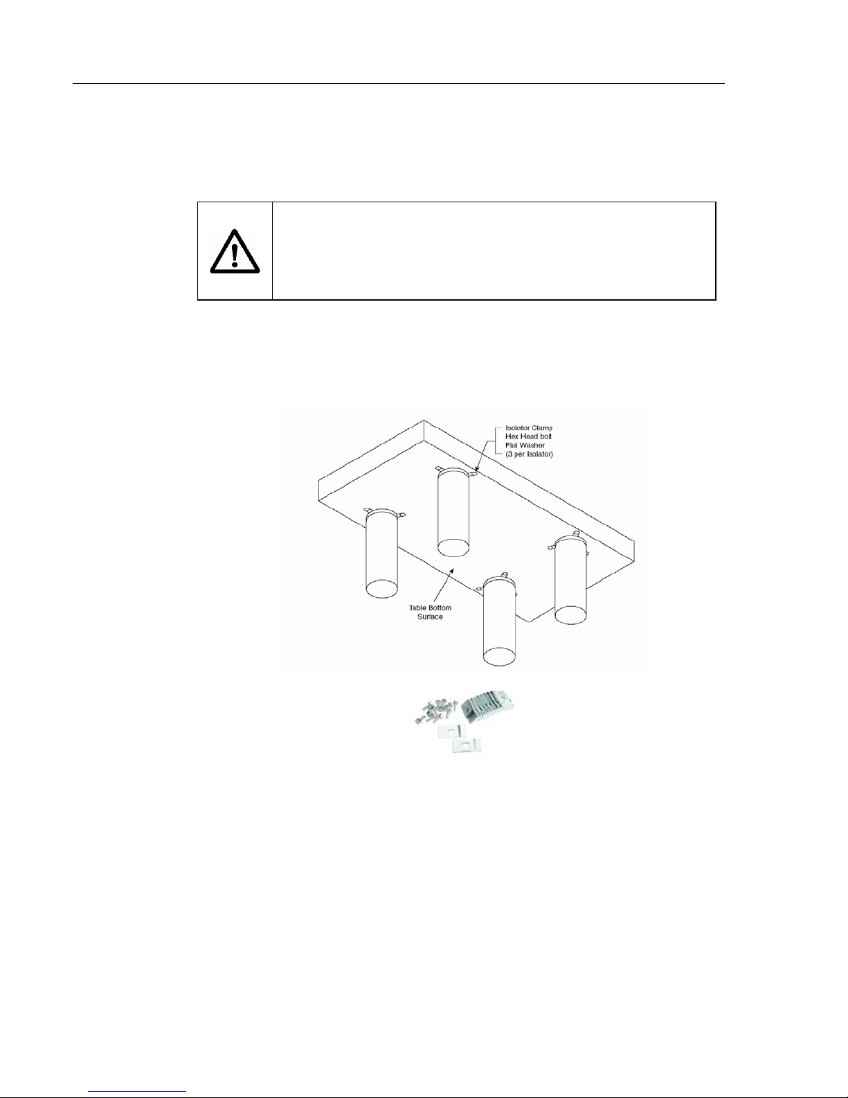
1. With the isolators located as described in Section 2.1.2, raise the table
top and position it above the isolators. Be sure each isolator is centered
within the tapped three-hole patterns on the lower surface of the table
(Figure 2).
WARNING
Figure 2 — Isolator Clamps and Mounting Holes
2. Gently lower the table so that is just above the top of isolators.
3. Install three isolator clamps in the corners where each isolator is located
(Figure 2). Loosely secure the clamps with the bolts. Do not tighten
the clamps at this time.
4. Lower the table top until it rests on the isolator support plates.
Page 13
When lowering the table on to the supports, do not allow the
table to shift sideways. Doing so could damage the isolators
and cause degradation in performance.
2.2 Leveling the Table
Use the following procedure to level the table. The special wrench (Figure 3)
is for all adjustments.
7
CAUTION
Figure 3 — Isolator Leveling Wrench
1. Refer to Figure 4. As shown, use one of the special wrenches to hold
the hex nut stationary. Insert the prongs of the second wrench into the
holes on the bottom of the support plate. Rotate the plate using the top
wrench to adjust the height.
2. Place a level on the table top, approximately in the center.
3. For each isolator, adjust the support plates as required to bring the table
to a level condition. Be sure to check the level using both the length and
width axes of the table. Verify that the centering disks are centered in
and resting on their respective guides (Figure 4).
Figure 4 — Level Adjustment of Isolators
Page 14

8
4. When the table is completely level, ensure by eye that every isolator
support plate is snug against the table bottom and that each centering
disk is centered in its guide (Figure 4).
5. Use the level to confirm that the tabl e top is still level and equally
supported by all isolator support plates. Tighten all isolator clamp bolts
snugly to secure the table to the isolators.
6. Loosen the two screws securing each leveling valve to its bracket. Slide
the valve body until it is approximately 0.060 inches (1.5mm) below the
bottom of the table. Be sure the valve is not tilted, then tighten the
screws (Figure 6).
2.3 Isolating the Table Top
2.3.1 Installing Leveling Valves
The IPV leveling valve is shown in Figure 5. Three valves are used in all
systems, regardless of the number of isolators, as only three points are
required to determine a plane. The leveling valve locations are selected such
that they form the largest triangle possible under the table. The larg er the
triangle, the more stable the system will be. When two or more isolators are
controlled by the same valve, they act as a single large isolator supporting the
table at the center of force of the several isolators. The floating height of the
system is determined at the valve position. Therefore, ideally, the valves
should be located at the center of force of the isolators they control. In
practice, however, simply grouping the isolators and their control valves is
sufficient. The groups of isolators and their valves act as three legs for the
system. The center of gravity of the combined table and payload must be
within the triangle formed by the centers of force of the isolator groups for
the system to float. Figure 8 shows valve and isolator arrangements for
rectangular tables. Complex table shapes require isolator and valve layouts
designed specifically for each application.
Page 15
9
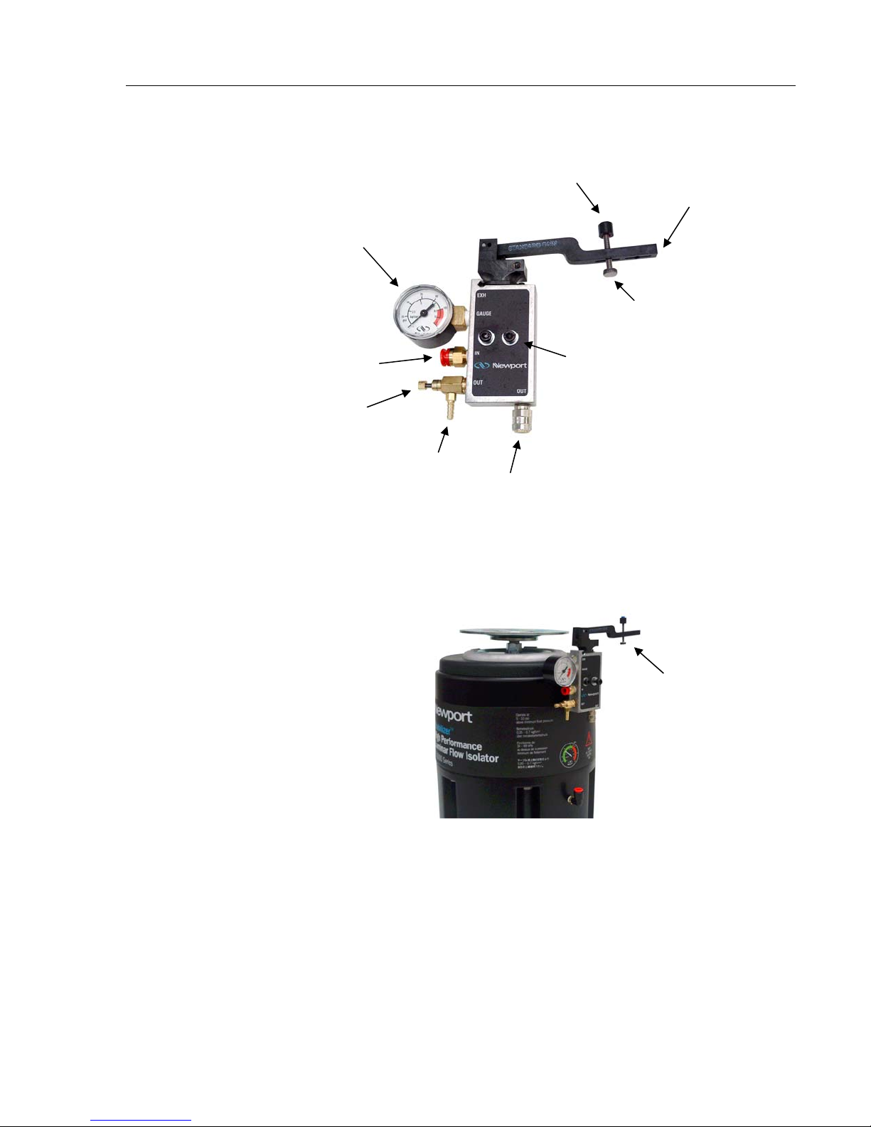
j
j
Table height sensor
Control arm
Isolator pressure
gauge
Table height
ad
ustment screw
Air supply
Metering
needle valve
Air line to isolator
Over-pressure relief valve
Figure 5 — IPV Leveling Valve
Mounting screw holes
Table height
ad
ustment screw
The valves should be attached to the isolators as shown in Figure 6 after
installing the table top.
1. Set the table height adjustment screw on each valve to the center of its
travel (Figure 6).
2. Attach the leveling valve to the isolators as shown in Figure 6. Secure
the valve to the bracket using the two mounting screws and the nutplate.
Figure 6 — Valves attaching to isolator
Page 16
10
Position the valve at the bottom of the bracket slots until after the table is
installed and leveled.
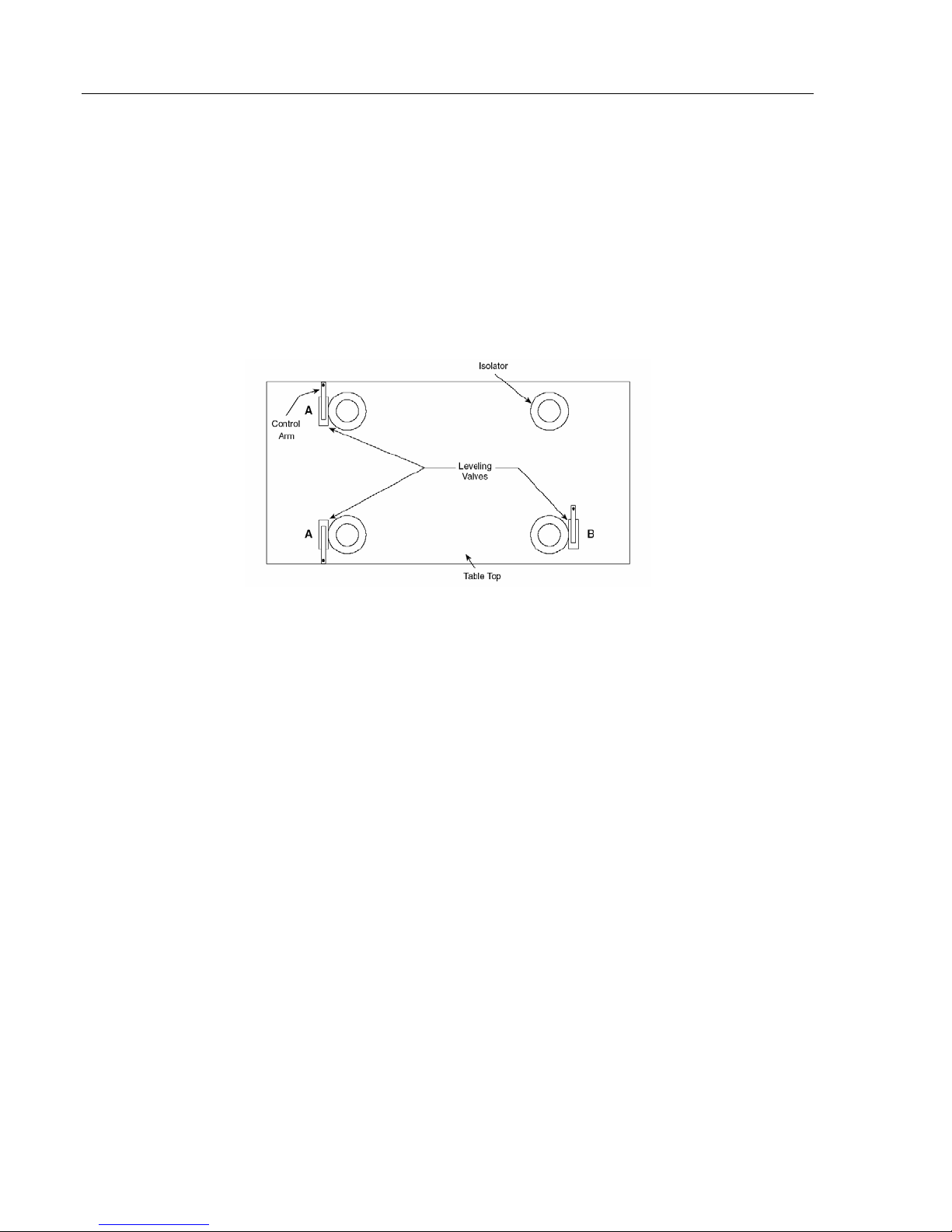
3. Rotate the control arm on valves “A” in Figure 7 so that they point
towards the nearest corner of the table.
4. Rotate the control arm on valve “B” in the figure so that it points toward
the table’s center, midway between the isolators that it controls.
5. For systems with more than four isolators, use the same basic setup just
described: Two valves control the height of the two end corners (A & A)
while the third valve (B) controls the height of the opposite end (Figure
8).
Figure 7 — Orientation of Control Arm
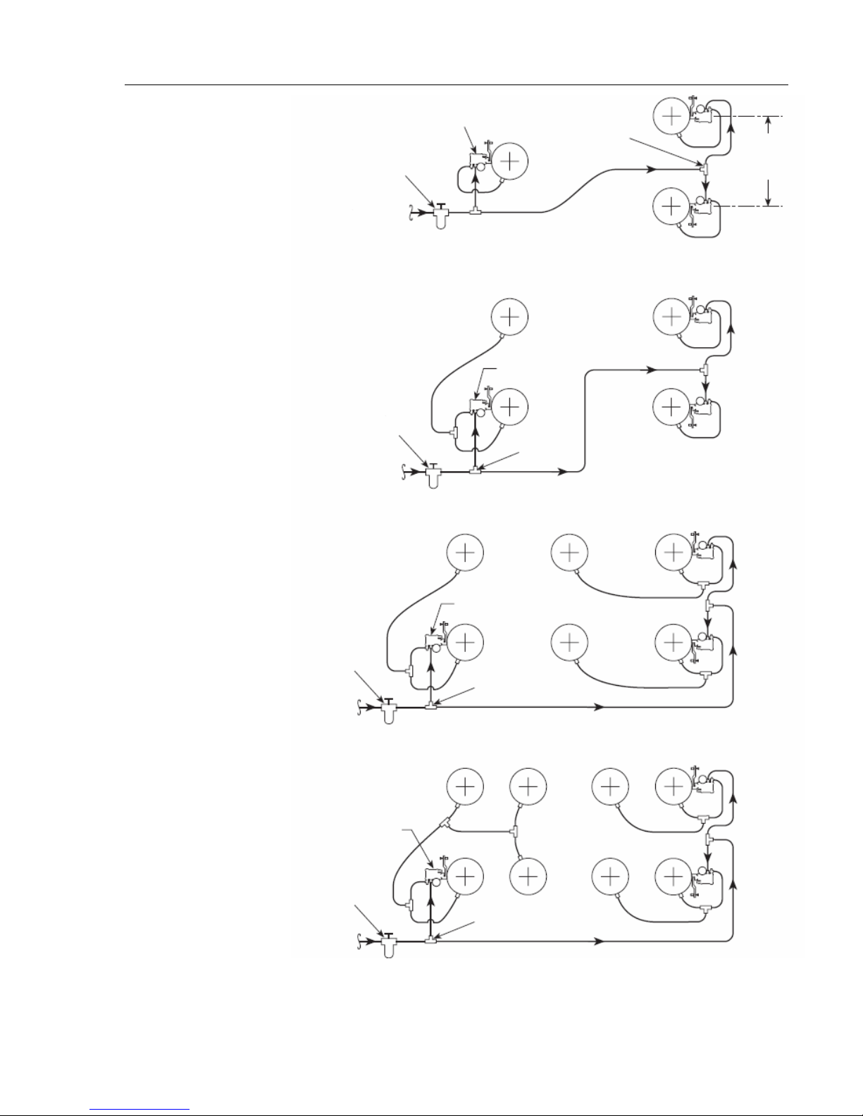
2.3.2 Connecting Air Lines
1. Connect air lines to the isolators as shown in Figure 8. When cutting
tubing, be sure the ends are round and cut squarely. This is best done
with a single edge razor blade (scissors will deform the tubing, causing
leaks). The connections are detailed in Figures 8, 9 and 10.
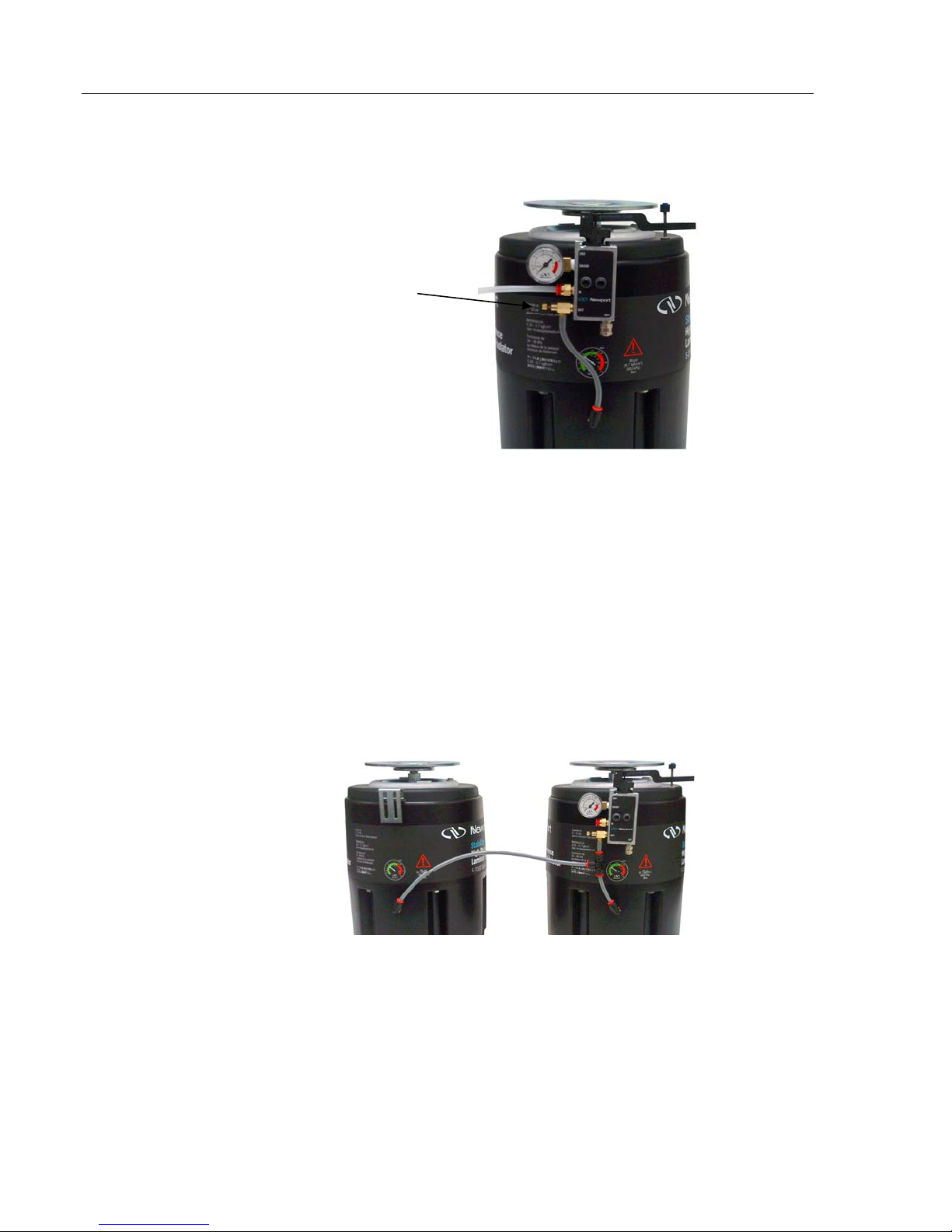
a. Use translucent tubing to connect the air supply to each of the
leveling valves. Use “Tee” connectors as required. Press the free
end of the tubing into the yellow collar of the valve’s “IN”
connector. Be sure the connection is firm by tugging on the tube.
b. Connect a length of grey tubing (supplied with the valves for use on
the valve barb fitting) between the hose barb on the valve and the
inlet connector on the isolator (Figure 9). If more than one isolator
is supplied by a valve, use “Tee” connectors as required (Figure 10).
Connect the grey tube from the valve to the “Tee” and use
translucent tubing between the “Tee” and each isolator.
Page 17
11
3 Isolator Schematic
Air
Regulator
Filter
Air Supply
4 Isolator Schematic
Air
Regulator
Filter
Air Supply
Leveling Valves
3 Reqd
Leveling Valves
3 Reqd
Tee
3 Reqd
Tee
2 Reqd
Table Width
Less 12”
Typ All Tables
6 Isolator Schematic
Air
Regulator
Filter
Air Supply
8 Isolator Schematic
Leveling Valves
3 Reqd
Air
Regulator
Filter
Air Supply
Leveling Valves
3 Reqd
Tee
5 Reqd
Tee
7 Reqd
Figure 8 — Air Line Routing
Page 18
12
Metering needle
valve
Figure 9 — Detail of Valve Connections, Single Isolator
2. Close the metering needle valve (Figure 9) on each valve and then open
it 1⁄2 turn for each isolator that is connected to it. For example, if the
valve controls two isolators, the needle valve is opened 1 full turn.
[Please note: If you have a minimum load on your optical table top, open
the metering valve about 1⁄8 – 1⁄4 of a turn.]
3. Turn on the air supply and adjust the regulator for the pressure calculated
using the formula given in Section 1.6. This pressure must not exceed
95psig (6.7 kg/cm2).
Figure 10 — Detail of Valve Connections, Two Isolators
4. Check all connections for leaks. Correct or repair any leaks before
proceeding.
5. If the table does not float within several minutes, increase the air
pressure until the table floats or adjust the value height sensors to hold
Page 19

pp
g
k
r
the control arms further down. Confirm that the needle valves are open
1
⁄2 turn per isolator supplied.
NOTE: If the table oscillates after it floats, decrease the air pressure or
close the needle valves slightly.
6. In clean room applications the “EXH” (exhaust) port on the valves may
be connected to the clean room vacuum system to capture the valve
exhaust.
NOTE: Exhaust must be routed to a vacuum system. Backpressure in
the tubing will cause the exhaust air to leak from the valve.
2.3.3 Adjusting Leveling Valve Sensors
1. After the table floats, check the position of the centering guide and
flange of all isolators (Figure 11). The gap between the guide and flange
1
should be
disk should be aligned with the float height indicator tabs (Figure 11).
2. Adjust the Table Height sensor screw of each isolator (Figure 5) as
required to obtain this gap. When all isolators are adjusted, re-check the
level of the table. NOTE: this step should require only minor
adjustments. Do not move the small set screw near the pivot of the valve
control arm.
⁄4" ± 1⁄16" (6mm ±1.5mm). The center of the isolator centering
13
3. If the table is no longer level, you may have to remove the air pressure
and re-adjust the height of the isolator support plates as described in
Section 2.
4. Verify that the table is freely floating on the isolators. Move the table
gently from side-to-side about
1
⁄8". You should not encounter any
resistance. Re-check by moving the table up and down the same amount.
Again, there should be no restriction of movement.
5. Push one corner of the table down approximately 1⁄8" and release it. The
table should return to the original position within less than 4 seconds.
Response time may be adjusted as described in Section 3.2.
Su
ort Plate
1/4” ± 1/16”
Centerin
Float height
indicato
dis
Page 20

14
Above alignment tabs
Even with alignment tabs Below alignment tabs
Too high Correct height Too low
Notice
gap
Incorrect centering Correct centering
Figure 11 — Floating Height Adjustment and centering
2.4 Installing tables with the Doubler Interface
The following instructions are applicable only to those tables equipped with
the Doubler Interface. Figure 12 shows a typical Doubler Interface System.
No gap
1. Use the procedures in Section 2.1.2 and 2.3.1 to assemble the isolators
for both table sections.
2. Carefully uncrate each table top, noting the correct orientation indicated
on the crates. Carefully check the doubler faces for any damage that
might prevent them from fitting tightly together.
Figure 12 — Typical Double Interface System
3. Position the isolators for one table section as described in Section 2.1.2.
Install valves on the appropriate isolators as shown in Figure 8.
4. Install the first table section on the isolators as described in
Section 2.1.3.
Page 21

15
NOTE: It may be necessary to use jack stands to support the first table
section if fewer than four isolators are located under the section.
5. Position the second table section on three jack stands mounted on dollies.
Adjust the position of the table so that it is at the same height as, and
adjacent to, the first table section.
6. Align the two table sections using a straight edge. Carefully roll the
second table section toward the first so that the alignment dowel pins
engage in their mating holes. Be sure the bolts are aligned with their
corresponding holes.
7. Draw the two table sections together approximately 1⁄8 inch (5mm) using
the two outermost top bolts.
CAUTION
Do not force the bolts. The second table section should be
easily pulled up to the first. Figure 2.13 shows correct bolt head
position during assembly.
Do not cause the first table section to shift sideways on its
isolators. Doing so could damage the isolators.
8. Tighten all of the bolts until they are finger-tight or until they just begin
to move the table sections together. Do not force or over-tighten the
bolts.
9. Repeat steps G and H until the two table sections are completely drawn
together.
10. When all bolts are snug, apply a final torque of 60 pound-feet (80 N-M)
to all bolts using the sequence shown in Figure 13.
11. Jack up the assembled table as required to install the remaining isolators
and leveling valves. Install the isolators and valves as described in
Section 2.1.
12. Remove the jack stands and level the table as described in
Section 2.3.
13. Install the air lines and float the table as described in Section 2.3.
Page 22

16
Figure 13 — Double Bolt Tightening Sequence
Page 23

3 Operation
3.1 Principles of Operation
The S-2000 Stabilizer™ Isolators provide one of the best methods of
vibration isolation for critical applications. The system operates on the
principle of air pistons, which are equivalent of soft springs. The main
advantage of the Newport system over other designs are low vertical resonant
frequency with low amplification at resonance (Q) and a Pendulum
horizontal decoupling system for effective isolation from low amplitude
vibration.
Newport optical tables provide a working surface that is statically rigid with
high internal tuned damping for high dynamic rigidity and minimal response
to environmental disturbances.
17
TM
The leveling valves provided with the system control the height of the table
to within ±0.01" (0.3mm) accuracy. This tolerance is adequate for most
applications. More accurate valves are available for specialized
applications.
3.2 Performance Adjustments
Once the system is assembled and the table floating, it is possible to make
minor adjustments to suit your individual needs. These adjustments involve
the system air pressure, the control arms, and needle valves.
WARNING
Once the table is floating, keep fingers away from the area
between the centering guide and outer clamp of the isolators.
Any object between these points may be caught if the table load
or air supply changes, causing personal injury.
1. Stabilizing high center-of-mass loads: If your load has a high center of
mass or if the load is particularly heavy, the table may oscillate. In this
case, lower the system pressure or close the needle valves slightly. This
may improve stability and reduce the oscillation or “hunting”.
2. A rule of thumb for determining high center of gravity (C-G) system
stability is shown in Figure 14. If the combined center of gravity of the
payload and table top is within the “stable region”, the system will be
stable. If the combined C-G is inside the “may be stable region”, the
Page 24

18
system may be stable. If the combined C-G is outside both regions, the
system will probably be unstable.
Figure 14 — System Stability
3. Improving leveling response times: If the system is stable, the re-
leveling response time may be decreased by increasing the system
pressure. In addition, the needle valves may be opened until the system
oscillates and then closed slightly. This is desirable if components are
moving over the surface of the table.
For systems where the loads are seldom changed, slower re-leveling may
be beneficial. This is accomplished by closing the needle valves slightly
and/or decreasing the system pressure.
All needle valves should be opened the same amount for each isolator
that they supply.
4. Table loads and/or load positions change: If the loads are moving or
changing significantly, the control arms may require adjustment. Each
time the load is changed, check the relationship of the centering guide to
the flange on each isolator. If the desired 1⁄4 inch is not maintained,
adjust the overall system pressure and/or the sensor positions.
Newport Vibration Control Systems require little maintenance. No periodic
maintenance is required.
3.3 Maintenance
3.3.1 Cleaning
Newport optical table tops are made of 400 series stainless steel. This
material is relatively corrosion resistant. It may be cleaned by applying nonabrasive liquid household cleaner to a rag and wiping the table top. Avoid
abrasive cleaners as they will foul the mounting holes.
All other surfaces on the table top or isolator system may be cleaned in the
same manner.
Page 25

3.3.2 Air Quality
Oil, water, or debris in the air supply may contaminate the leveling valves or
isolator damping system and degrade performance. Use of the Newport
model ARF Air Regulator and Filter in the air supply will prevent this
occurrence. The filter does require occasional cleaning.
19
Page 26

20
4 Troubleshooting
4.1 Table Top Does Not Float
Use the following procedure if the table top does not float, or lift up, when
pressure is applied to the isolators.
1. Ensure that the supply pressure is 5–10 psig (0.4–0.7kg/cm
pressure reading of any of the leveling valves. If the load is increased,
the pressure should be increased to maintain the difference between
supply and valve pressure. Refer to Section 1.6.
2. Check to see if all air lines are connected properly and the supply
pressure is adequate (see step 1). Refer to Figures 8, 9, and 10.
2
) above the
3. Be sure that the needle valves are not closed completely.
4. Check each leveling valve for clogging. To do this, press the control
arm down. Air should flow into the isolator, accompanied by the
familiar sound of moving air. Repair or replace any clogged valve. Use
the ARF filter/regulator to prevent this situation.
4.2 Poor Isolation Performance
The following may lead to poor isolation performance of your system.
1. Vibration may be transmitted to the table through direct physical contact
of equipment with external sources of vibration.
2. Isolators that float too high, too low, or are not centered may conduct
floor vibration to the table top. Refer to Section 2.3.2. (Figure 11)
Centered isolators will remain centered unless the table and isolators are
moved relative to each other.
3. Equipment on the table may be vibrating at a resonant frequency of other
components. Improve the rigidity of the mounting for that equipment or
remove that item from the table.
4. Non-level floor may prevent the horizontal isolation system from
functioning properly (see Section 1.5).
Page 27

4.3 Table Top Oscillates
If the table top oscillates or “hunts”, you may have a set up with a high center
of mass. Refer to the information in Section 3.2 or consult your Newport
representative or Newport Corporation for further assistance.
4.4 System Leaks Air Constantly
All Newport isolators and valves are pressure leak tested prior to shipment.
Check all tubing connections for leaks with soapy water. Tubing that is
crushed out of round or that is not cut squarely may not seal in the push-in
fittings. Use a single edge razor blade to cut the tubing cleanly (refer to
Section 2.3.2). If testing with soapy water indicates that either the isolator or
valve are leaking contact Newport Customer Service.
4.5 Oil Leak From Isolator
Damping oil may leak from the isolator if it is inverted or tilted more than 45
degrees. If more than 1⁄8 cup (30ml) of oil is lost, add additional oil (available
from Newport Corporation) as directed in Section 4.6. Losses of less than
1
⁄8 cup will not affect the isolator performance. Total volume of damping oil
per isolator is approximately 1⁄2 cup (125ml).
21
4.6 Adding Damping Oil
If the isolator loses damping oil, additional oil may be added as follows:
1. Remove the air pressure from the isolator and allow the piston to retract.
Ensure that the remaining isolators will support the table or use a jack
stand to replace the isolator to be serviced. Loosen the three bolts
securing the support plate to the bottom of the table, and slide the
isolator from under the system.
The table top is heavy and may cause severe personal injury if it
falls! Be sure it is properly supported before getting underneath
the table top or removing the isolator.
2. Measure the height of the support plate relative to the centering disk
(Figure 2.4). Record this distance so that the isolator may be returned to
its normal position.
3. Unscrew the isolator support screw (right-hand thread) and remove the
plate and jack screw from the piston assembly.
4. Use a funnel to add damping oil through the support shaft hole until the
oil level is approximately
Allow time for the viscous oil to settle before measuring the oil level.
WARNING
1
⁄4" (6.4mm) from the bottom of the piston.
Page 28

22
5. Use a clean, small diameter rod to check the level. When checking the
level, be sure the rod sits on the bottom of the piston and not on the
narrow ledge at the bottom of the support shaft.
6. Reverse Steps 2 and 3 to re-assemble the isolator. Return the support
plate to the position noted in Step 2.
7. Reinstall the isolator and apply air pressure. Make any required
adjustments to return the system to operation.
Page 29

5 Factory Service
To obtain information concerning factory service, contact Newport
Corporation or your Newport representative. Please have the following
information available.
1. Model number.
2. Purchase order number.
3. Complete description of the problem.
If components are to be returned to Newport Corporation, you will be given a
Return Number, which you should reference in your shipping documents.
23
Please fill out the service form located on the next page, and have the
information ready when contacting Newport Corporation. Include the
completed service form with any parts or components that are returned.
Page 30

Lead
<0.1% (1000 PPM)
Mercury
<0.1% (1000 PPM)
Cadmium
<0.01% (100 PPM)
Hexavalent Chromium
<0.1% (1000 PPM)
Polybrominated Biphenyls (PBB)
<0.1% (1000 PPM)
Polybrominated Diphenyl Ethers (PBDE)
<0.1% (1000 PPM)
Product
RoHS Compliant Part Number
SUPPORT SYSTEM,TIE BAR,S-2000
S-2000A-428-TC
_____________6/6/18_________________
Date
RoHS
(Restriction of Hazardous Substances)
Certificate of Compliance
MKS Instruments, Inc. hereby certifies that the products listed in the table below are compliant
with the European Union’s RoHS directive 2011/65/EU (effective 22 July 2017) regarding the
restriction of the use of certain hazardous substances in electrical and electronic equipment. The
products listed below are compliant to RoHS requirements for concentration limitations, by weight
of homogeneous material, of the following six substances:
The above thresholds are not in place for any legally allowable exemptions per Annex III of the
aforementioned directive. If such exemptions are in use, they are noted on the attached table. If no
exemptions are in use, then no further information is provided.
All information provided in this Certificate of Compliance is accurate to MKS’ knowledge as of the
date of this certification. This confirmation is made based our internal engineering risk analysis of
the individual items possibly being present along with the best technical information made available
to MKS from its material suppliers.
MKS Instruments, Inc. Page 1 of 2 Document Number: MKS-CD-1138
MKS CONFIDENTIAL Revision: B
Page 31

MKS Product
Number
MKS Product
Description
Annex III
Exemption #
Annex III
Exemption Description
MKS RoHS2 PRODUCT EXEMPTION LISTING
MKS Instruments, Inc. Page 2 of 2 Document Number: MKS-CD-1138
MKS CONFIDENTIAL Revision: B
Page 32

Vibration Control
System
I
NSTRUCTION
M
ANUAL
Page 33

Warranty
Newport Corporation warrants isolator products to be free of defects in
material and workmanship for a period of two years from the date of
shipment. In addition, the laminated honeycomb tops have an extended
lifetime warranty against delamination of the skins under normal use and
proper handling. If found to be defective during the warranty period, the
product will either be repaired or replaced at Newport’s option.
To exercise this warranty, write or call your local Newport representative
or contact Newport headquarters in Irvine, California. You will be given
prompt assistance and return instructions.
Repaired or replaced products are warranted for the balance of the original
warranty period or 90 days, whichever is longer.
This warranty does not apply to defects resulting from modifications or
improper use of the system or its component parts.
This warranty is in lieu of all other warranties, expressed or implies,
including any implied warranty of merchantability or fitness for a particular use. Newport Corporation shall not be liable for any indirect, special,
or consequential damages.
©1991, Newport Corporation
Irvine, California, U.S.A.
P/N 18615-01 Rev. H4
IN-04913 (08-00)
ii
Page 34

Table of Contents
Warranty ............................................................................................................... ii
List of Figures ..................................................................................................... iv
Specifications ....................................................................................................... v
Section 1 — General Information .....................................................................1
1.1 Introduction ............................................................................................ 1
1.2 Getting Started ........................................................................................1
1.3 Unpacking and Inspection .....................................................................1
1.4 Safety Considerations ............................................................................1
1.5 Table Placement .....................................................................................3
1.6 Air Supply Requirements ...................................................................... 3
1.7 Warranty Information ............................................................................ 4
1.8 Options and Accessories .......................................................................5
Section 2 — Assembly .........................................................................................6
2.1 Assembling the System..........................................................................6
2.1.1 Table Installation Assistance .................................................... 6
2.1.2 Positioning the Isolators ............................................................ 6
2.1.3 Installing Table Top .................................................................... 7
2.2 Leveling the Table ................................................................................. 8
2.3 Isolating the Table Top ..........................................................................9
2.3.1 Installing Leveling Valves .......................................................... 9
2.3.2 Connecting Air Lines ................................................................ 11
2.3.3 Adjusting Leveling Valve Sensors........................................... 14
2.4 Installing Tables with the Doubler Interface ................................... 15
Section 3 — Operation ..................................................................................... 17
3.1 Principles of Operation ...................................................................... 17
3.2 Performance Adjustments ................................................................. 17
3.3 Maintenance ......................................................................................... 18
3.3.1 Cleaning ...................................................................................... 18
3.3.2 Air Quality .................................................................................. 18
3.3.3 Spare Parts ................................................................................. 19
Section 4 — Troubleshooting ......................................................................... 20
4.1 Table Top Does Not Float ................................................................... 20
4.2 Poor Isolation Performance ............................................................... 20
4.3 Table Top Oscillates............................................................................ 20
4.4 System Leaks Air Constantly ............................................................. 20
4.5 Oil Leaking From Isolator ................................................................... 21
4.6 Adding Damping Oil ............................................................................ 21
Section 5 — Factory Service ........................................................................... 22
5.1 Obtaining Factory Service.................................................................. 22
5.2 Service Form ........................................................................................ 23
iii
Page 35

List of Figures
Figure Title Page
1.1 Vibration Control System Assembly ..................................................... 2
2.1 Isolator Position .......................................................................................6
2.2 Isolator Clamps and Mounting Holes ....................................................7
2.3 Isolator Leveling Wrench ........................................................................8
2.4 Level Adjustment of Isolators ................................................................8
2.5 IPV Leveling Valve ................................................................................... 9
2.6 Leveling Valve Mounting ...................................................................... 10
2.7 Orientation of Control Arm .................................................................. 11
2.8 Air Line Routing ..................................................................................... 12
2.9 Detail of Valve Connections, Single Isolator...................................... 13
2.10 Detail of Valve Connections, Two Isolators ....................................... 13
2.11 Floating Height Adjustment ................................................................. 14
2.12 Typical Doubler Interface System....................................................... 15
2.13 Doubler Bolt Tightening Sequence ..................................................... 16
3.1 System Stability ..................................................................................... 18
3.2 Stabilizer™ Spare Parts ........................................................................ 19
iv
Page 36

Specifications
Table Tops:
Flatness: ±0.005in. (0.13mm)*
Compliance: Consult your Newport Catalog or Newport
directly for the specific compliance and
other pertinent table top specifications of
your particular table top model.
Isolators: Stabilizer™ I-2000
Vertical Resonant
Frequency: <1.1 Hz at 80 psi
Horizontal Resonant
Frequency: <1.5 Hz
Recommended Load
Range:
(per 4 isolators) 660 to 8,000 lb (300 to 3,600 kg)
Automatic Leveling
Accuracy: ±0.010 inch (0.25 mm) standard,
higher accuracy available on
special order
Vertical Adjustment
Range: 1.3 inches (33 mm)
Settling Time:
(after 5-lb. weight removal) <1.5 sec.
Typical Air Pressure
Range: 10 to 85 psi (0.7 to 6.0 kg/cm
2
)
* Flatness value provided for a typical 4' × 8' × 12" table. Request Newport
“Table Quality Specification” for complete specifications.
v
Page 37

Isolation System Transmissibility
10
1
0.1
TRANSMISSIBILITY (T)
0.01
0.001
0.8 1 10 30
Vertical Transmissibility (at maximum recommended load)
5
1
FREQUENCY (Hz)
0.1
TRANSMISSIBILITY (T)
0.01
0.5 1 10 25
FREQUENCY (Hz)
Horizontal Transmissibility
vi
Page 38

Valve: Model IPV
Leveling Accuracy: ±0.010 in (.25 mm) standard**
Materials: Glass fiber reinforced polycarbonate
brass
Available in non-magnetic version
Exhaust may be captured by clean room
vacuum system
** Higher accuracies are available by special order.
Table Height Sensor
Exhaust Port
1⁄8 NPT
Isolator
Pressure Gauge
Air Supply Line
Metering
Needle Valve
Over-pressure
Relief Valve
Mounting
Screw
Holes
Control Arm
Air Line to Isolators
Model IPV Leveling Valve
vii
Page 39

viii
Page 40

Section 1
General Information
Introduction
1.1
Getting Started
1.2
The Newport Vibration Control System provides an ideal working platform for
vibration sensitive devices such as interferometers, microscopes, and balances.
The table surface is isolated from floor motion using the Stabilizer™ pneumatic
suspension system. The versatile Newport Vibration Control System is available
in a variety of sizes, working surfaces, and options.
These systems integrate Newport’s rigid, laminated honeycomb panel technology and pneumatic isolation systems to provide a mounting platform which is
rigid, yet thin and light weight.
It is possible to tailor the system to a wide variety of applications using the
entire range of sizes and working surfaces. A typical Newport Vibration
Control System is shown in Figure 1.1
The Stabilizer™ isolation system is capable of supporting 2000 pounds
per isolator. Caution must be observed to ensure that heavy payloads are
not located off center on the table surface. This could cause overloading
of one isolator even though the average load per isolator is below the
2000 pound limit.
Heavy payloads with very high centers of gravity (C-G) may cause the
isolation system to oscillate. Please consult Section 3.2 of this manual or
Newport Applications Engineering for high C-G applications.
Please read this instruction manual thoroughly before assembling the table
system. The individual components have been assembled at the factory
and require only final system assembly and performance adjustment.
Unpacking and
1.3
Inspection
Safety Considerations
1.4
The components of your Newport Vibration Control System are packed in
individual, labeled boxes. Be sure the number of boxes you received is
equal to the total number listed on the label (for example, if a box is labeled
1 of 4, there should be 4 boxes).
Use the photographs in Figure 1.1 to locate and identify each component as
you remove it from the box. Carefully inspect all components for shipping
damage. Report any shipping damage immediately to Newport and the
shipping company.
The following terms are used in this manual that relate to your safety.
Warning is used to indicate dangers that could result in personal injury.
Caution is used to indicate situations that may result in damage to compo-
nents of your Newport Vibration Control System.
1
Page 41

Clamp
(3 per Isolator)
Wrench Holes
Level
Adjustment
Screw
Stabilizer™
Isolator
Leveling Valve
(3 per system)
Figure 1.1 — Vibration Control System Assembly
Leveling Valve
(3 per system)
2
Page 42

Table Placement
1.5
To ensure optimal performance from your Vibration Control System, it
should be located on a level surface. Uneven floors may cause difficulty
during the leveling of the table top if their irregularity is outside of the
adjustment range of the isolators.
The Stabilizer™ isolator must be mounted so that its axis is not more than
0.5 degrees from vertical. This is necessary for the isolator to function
properly in the horizontal mode. Note: 0.5 degrees is equal to 0.09 (2.2 mm)
inches in 10.0 inches which is the isolator base diameter. A typical spirit
level will easily measure 0.5 degrees and can be used to check the vertical
alignment of each isolator.
If the floor where the isolators are being mounted has a depression of more
than 0.09 inches under one side of the base, then the floor should be
grouted or shimmed level at this location.
If the system is not located on the ground floor of the building, it should be
located near primary vertical structures such as exterior walls or support
columns. By locating the table near these structures, the effects of low
frequency floor motion will be minimized, thus increasing the performance
of the table. It is also advisable to avoid locations adjacent to major
sources of vibration from operating machinery such as elevators, air
conditioning plants, or factory equipment.
Warning
The table top is attached to the isolators with clamps and hex head
bolts. In the event of an earthquake, the table may collapse. For
areas susceptible to earthquakes, we recommend that Newport
Earthquake Restraints be installed on each Vibration Control
System.
Air Supply
1.6
Requirements
The table top is a metallic electrical conductor. For installations
where electrical shock is a possibility, the table top should be
grounded to prevent personal injury.
A constant supply of air must be connected to the Vibration Control System
during operation. After initial setup and filling, the isolators consume air
only when the leveling valves adjust the pressure to compensate for
changes in the load on the table.
Bottled nitrogen or mechanically compressed air may be used. The
required pressure is determined by dividing the total load, including table
weight, by the total isolator diaphragm area (25.9 in2 per isolator) plus
5-10 psig.
For example, if the table plus load is 2850 pounds and will be mounted on 4
isolators, the required pressure is:
2850
lbs
4259
×
.
Note that the maximum operating pressure for the system is 100 psig
(7.0 kg/cm2).
The Newport Model ACMP air compressor is an extremely quiet source of
clean, pressure regulated air. If another compressor or plant air is used,
10 33 8
psig psig
+=
2
in
.
3
Page 43

the Newport model ARF Air Regulator/Filter should be used to ensure
maintenance free operation. These filters prevent water and dirt from
getting into the leveling valves and causing the valves to fail due to
clogging.
The supply should include a valve so that the air may be shut off during
maintenance or extensive setup when the load is changed drastically.
Caution
Bottled carbon dioxide (CO2) is not recommended since “icing”
can occur during rapid filling of the isolators.
War ranty Information
1.7
Warranty information may be found on the page preceding the Table of
Contents in this manual. Should it become necessary to exercise the
warranty, contact your Newport representative to determine the proper
course of action. Newport Corporation maintains offices throughout the
United States and other locations worldwide. Refer to the back cover of
this manual for the addresses and telephone numbers of these offices.
4
Page 44

1.8
Options and
Accessories
Your Vibration Control System may include one or more of the following
options.
Options Model No.
Air Compressor .............................................................................ACMP
Retractable Casters ......................................................................XLC
Tie Bar & Caster Set ......................................................................XLTC-XXX
Doubler Interface .......................................................................... RSD, RSW
Laser Access Hole .........................................................................AH
Clean Room Valve Exhaust System .............................................CE-1
Earthquake Restraint System ...................................................... ER
Accessories Model No.
Overhead Shelf Systems
6' long .................................................................................... ATS-6
8' long .................................................................................... ATS-8
10' long .................................................................................. ATS-10
Accessory Shelf ............................................................................. AS-1568
Beam Steering Instruments
Damped .................................................................................675TS
Standard ................................................................................ 670TS
Table Enclosures - 32" (81.3 cm) high
4' × 6' ......................................................................................TE1406
4' × 8' ......................................................................................TE1408
4' × 10' ....................................................................................TE1410
4' × 12' ....................................................................................TE1412
4' × 14' ....................................................................................TE1414
4' × 16' ....................................................................................TE1416
4' × 18' ....................................................................................TE1418
4' × 20' ....................................................................................TE1420
5' × 8' ......................................................................................TE1508
5' × 10' ....................................................................................TE1510
5' × 12' ....................................................................................TE1512
5' × 14' ....................................................................................TE1514
5' × 16' ....................................................................................TE1516
5
Page 45

Section 2
Assembly
2.1
Assembling
the System
2.1.1 Table Installation Assistance
Optical tables are heavy. Even a small table top weighs over 500 pounds
(227 Kg). Contact Newport or your local sales representative for help in
preparing your facility.
2.1.2 Positioning the Isolators
Figure 2.1 shows the correct isolator positions for standard table sizes.
Table 2.1 shows the correct dimensions (A, B, & C) for each table size. If
your table is not listed, the isolator positions for your table will be included
in the data package provided with the system.
C
B Typ.
Figure 2.1 — Isolator Position
Table 2.1 — Isolator Positions
Table Length Distance A Distance B Distance C
6' 40" 987mm 16" 406mm 6" (152mm)
8' 52" 1282mm 22" 559mm from edge of
10' 66" 1628mm 27" 686mm table
12' 80" 1974mm 32" 813mm
14' 94" 2420mm 37" 940mm
16' 104" 2565mm 42" 1087mm
18' 120" 2962mm 47" 1194mm
20' 134" 3308mm 53" 1346mm
A
6" (152 mm)
4 PL
6
Page 46

2.1.3 Installing Table Top
If your table is equipped with the Doubler Interface be sure to follow the
instructions in Section 2.4 for assembling the table sections prior to installing
them on the isolators.
Warning
Table tops are heavy! As described in Section 2.1.1, use a forklift
or other appropriate equipment. Be sure to use proper lifting
procedures to avoid severe personal injury.
A. With the isolators located as described in Section 2.1.2, raise the table
top and position it above the isolators. Be sure each isolator is
centered within the tapped three-hole patterns on the lower surface
of the table (Figure 2.2).
Isolator Clamp
Hex Head bolt
Flat Washer
(3 per Isolator)
Table Bottom
Surface
Figure 2.2 — Isolator Clamps and Mounting Holes
B. Gently lower the table so that is just above the top of isolators.
C. Install three isolator clamps in the corners where each isolator is
located (Figures 1.1 & 2.2). Loosely secure the clamps with the bolts.
Do not tighten the clamps at this time.
D. Lower the table top until it rests on the isolator support plates.
Caution
When lowering the table on to the supports, do not allow the table
to shift sideways. Doing so could damage the isolators.
7
Page 47

Leveling the Table
2.2
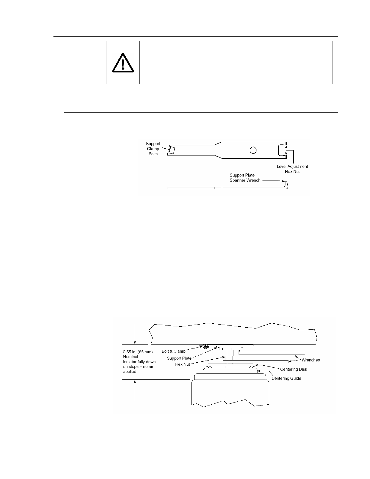
Use the following procedure to level the table. The special wrench (Figure
2.3) is for all adjustments.
Support
Clamp
Bolts
Level Adjustment
Support Plate
Spanner Wrench
Hex Nut
Figure 2.3 — Isolator Leveling Wrench
A. Refer to Figure 2.4. As shown, use one of the special wrenches to hold
the hex nut stationary. Insert the prongs of the second wrench into
the holes on the bottom of the support plate. Rotate the plate using
the top wrench to adjust the height.
B. Place a level on the table top, approximately in the center.
C. For each isolator, adjust the support plates as required to bring the
table to a level condition. Be sure to check the level using both the
length and width axes of the table. Verify that the centering disks are
centered in and resting on their respective guides (Figure 2.4).
2.55 in. (65 mm)
Nominal
Isolator fully down
on stops – no air
applied
Bolt & Clamp
Support Plate
Hex Nut
Centering Disk
Centering Guide
Figure 2.4 — Level Adjustment of Isolators
D. When the table is completely level, ensure by eye that every isolator
support plate is snug against the table bottom and that each centering disk is centered in its guide (Figure 2.4).
E. Use the level to confirm that the table top is still level and equally
supported by all isolator support plates. Tighten all isolator clamp
bolts snugly to secure the table to the isolators.
F. Loosen the two screws securing each leveling valve to its bracket.
Slide the valve body until it is approximately 0.060 inches (1.5mm)
below the bottom of the table. Be sure the valve is not tilted, then
tighten the screws.
Wrenches
8
Page 48

2.3
Isolating the
Table Top
2.3.1 Installing Leveling Valves
The IPV leveling valve is shown in Figure 2.5. Three valves are used in all
systems, regardless of the number of isolators, as only three points are
required to determine a plane. The leveling valve locations are selected
such that they form the largest triangle possible under the table. The larger
the triangle, the more stable the system will be. When two or more isolators
are controlled by the same valve, they act as a single large isolator supporting the table at the center of force of the several isolators. The floating
height of the system is determined at the valve position. Therefore, ideally,
the valves should be located at the center of force of the isolators they
control. In practice, however, simply grouping the isolators and their
control valves is sufficient. The groups of isolators and their valves act as
three legs for the system. The center of gravity of the combined table and
payload must be within the triangle formed by the centers of force of the
isolator groups for the system to float. Figure 2.8 shows valve and isolator
arrangements for rectangular tables. Complex table shapes require isolator
and valve layouts designed specifically for each application.
Control Arm
Assy
Table Height Sensor
Adjustment Screw
Pivot Clamp
Screw
Exhaust
Metering
Needle Valve
Mounting Screws (2)
Washers (2)
Barb Fitting
Air
Supply
Control Arm
Adjustment Screw
(Preset at Factory)
EXH
GAGE
OUT
OUT
Mounting Bracket
Pressure
Relief Valve
Nut Plate
Factory Sealed —
Do Not Remove
Figure 2.5 — IPV Leveling Valve
9
Page 49

Control Arm
EXH
GAGE
Valve
Mounting
Bracket
Nut &
Washer
Mounting Screws (2)
Washers (2)
10-32 Screws (2)
OUT
Leveling Valve
Nut Plate
OUT
Figure 2.6 — Leveling Valve Mounting
The valves should be attached to the isolators as shown in Figure 2.6 after
installing the table top.
A. Set the table height adjustment screw on each valve to the center of
its travel.
B. Attach the leveling valve to the isolators as shown in Figure 2.6.
Secure the valve to the bracket using the two mounting screws and
the nutplate. Position the valve at the bottom of the bracket slots
until after the table is installed and leveled.
C. Rotate the control arm on valves “A” in Figure 2.7 so that they point
towards the nearest corner of the table.
D. Rotate the control arm on valve “B” in the figure so that it points
toward the table’s center, midway between the isolators that it
controls.
10
Page 50

E. Gently tighten the clamping screw on the control arm pivot.
(Figure 2.5)
F. For systems with more than four isolators, use the same basic setup
just described: Two valves control the height of the two end corners
(A & A) while the third valve (B) controls the height of the opposite
end. See Figure 2.8.
Isolator
A
Control
Arm
Leveling
Valves
AB
Table Top
Figure 2.7 — Orientation of Control Arm
2.3.2 Connecting Air Lines
A. Connect air lines to the isolators as shown in Figure 2.8. When
cutting tubing, be sure the ends are round and cut squarely. This is
best done with a single edge razor blade (scissors will deform the
tubing, causing leaks). The connections are detailed in Figures 2.9
and 2.10.
1. Use translucent tubing to connect the air supply to each of the
leveling valves. Use “Tee” connectors as required. Press the free
end of the tubing into the yellow collar of the valve’s “IN” connector. Be sure the connection is firm by tugging on the tube.
11
Page 51

3 Isolator Schematic
4 Isolator Schematic
Table Width
Less 12"
Typ All Tables
Te e
2 Reqd
Leveling Valves
3 Reqd
Te e
3 Reqd
Leveling Valves
3 Reqd
Air
Regulator
Filter
Air Supply
Air
Regulator
Filter
Air Supply
6 Isolator Schematic
8 Isolator Schematic
Leveling Valves
3 Reqd
Te e
5 Reqd
Te e
7 Reqd
Air
Regulator
Filter
Air Supply
Leveling Valves
3 Reqd
Air
Regulator
Filter
Air Supply
Figure 2.8 — Air Line Routing
12
Page 52

2. Connect a length of grey tubing (supplied with the valves for use on
the valve barb fitting) between the hose barb on the valve and the
inlet connector on the isolator (Figure 2.9). If more than one isolator
is supplied by a valve, use “Tee” connectors as required (Figure 2.10).
Connect the grey tube from the valve to the “Tee” and use translucent
tubing between the “Tee” and each isolator.
Table Bottom
Sensor
Control
Arm
Air
Suppl
yy
Metering Needle
EXH
GAGE
IN
OUT OUT
Attachment
Screws
Leveling Valve
Valve
Barb Fitting
Grey Tubing
Figure 2.9 — Detail of Valve Connections, Single Isolator
B. Close the metering needle valve (Fig. 2.9) on each valve and then open it
1
⁄2 turn for each isolator that is connected to it. For example, if the valve
controls two isolators, the needle valve is opened 1 full turn. [Please note:
If you have a minimum load on your optical table top, open the metering
valve about 1⁄8 – 1⁄4 of a turn.]
C. Turn on the air supply and adjust the regulator for the pressure calculated
using the formula given in Section 1. This pressure must not exceed 100
psig (7.0 kg/cm2).
Figure 2.10 — Detail of Valve Connections, Two Isolators
Sensor
Control
Arm
Translucent
Tubing
Air
Suppl
yy
Barb Fitting
13
Table Bottom
EXH
GAGE
IN
OUT OUT
Attachment
Screws
Leveling Valve
Grey Tubing
Te e
Page 53

D. Check all connections for leaks. Correct or repair any leaks before
proceeding.
E. If the table does not float within several minutes, increase the air
pressure until the table floats or adjust the value height sensors to
hold the control arms further down. Confirm that the needle valves
are open 1⁄2 turn per isolator supplied.
NOTE: If the table oscillates after it floats, decrease the air pressure
or close the needle valves slightly.
F. In clean room applications the “EXH” (exhaust) port on the valves
may be connected to the clean room vacuum system to capture the
valve exhaust. Order Newport kit #CE-1.
NOTE: Exhaust must be routed to a vacuum system. Backpressure in
the tubing will cause the exhaust air to leak from the valve.
2.3.3 Adjusting Leveling Valve Sensors
A. After the table floats, check the position of the centering guide and
flange of all isolators (Figure 2.11). The gap between the guide and
flange should be 1⁄4" ± 1⁄16" (6mm ±1.5mm).
B. Adjust the Table Height sensor screw of each isolator (Figure 2.5) as
required to obtain this gap. When all isolators are adjusted, re-check
the level of the table. NOTE: this step should require only minor
adjustments. Do not move the small set screw near the pivot of the
valve control arm.
C. If the table is no longer level, you may have to remove the air pressure
and re-adjust the height of the isolator support plates as described in
Section 2.2.
D. Verify that the table is freely floating on the isolators. Move the table
gently from side-to-side about 1⁄8". You should not encounter any
resistance. Re-check by moving the table up and down the same
amount. Again, there should be no restriction of movement.
E. Push one corner of the table down approximately 1⁄8" and release it.
The table should return to the original position within less than 4
seconds. Response time may be adjusted as described in Section 3.2.
Support Plate
Centering Disk
Centering
Guide
1/4" ± 1/16"
Figure 2.11 — Floating Height Adjustment
14
Page 54

Installing Tables with
2.4
the Doubler Interface
The following instructions are applicable only to those tables equipped with
the Doubler Interface. Figure 2.12 shows a typical Doubler Interface System.
A. Use the procedures in Section 2.1.2 and 2.3.1 to assemble the isolators
for both table sections.
B. Carefully uncrate each table top, noting the correct orientation
indicated on the crates. Carefully check the doubler faces for any
damage that might prevent them from fitting tightly together.
Doubler Faces
Table
Section
Alignment Dowel
Pins
Doubler Bolts
Table
Section
Figure 2.12 — Typical Double Interface System
C. Position the isolators for one table section as described in Section
2.1.2. Install valves on the appropriate isolators as shown in
Figure 2.7.
D. Install the first table section on the isolators as described in
Section 2.1.3.
NOTE: It may be necessary to use jack stands to support the first
table section if fewer than four isolators are located under
the section.
E. Position the second table section on three jack stands mounted on
dollies. Adjust the position of the table so that it is at the same height
as, and adjacent to, the first table section.
F. Align the two table sections using a straight edge. Carefully roll the
second table section toward the first so that the alignment dowel pins
engage in their mating holes. Be sure the bolts are aligned with their
corresponding holes.
G. Draw the two table sections together approximately 1⁄8 inch (5mm)
using the two outermost top bolts.
Caution
Do not force the bolts. The second table section should be easily
pulled up to the first. Figure 2.13 shows correct bolt head position
during assembly.
Do not cause the first table section to shift sideways on its isolators.
Doing so could damage the isolators.
15
Page 55

H. Tighten all of the bolts until they are finger-tight or until they just
begin to move the table sections together. Do not force or overtighten the bolts.
I. Repeat steps G and H until the two table sections are completely
drawn together.
J. When all bolts are snug, apply a final torque of 60 pound-feet (80 N-M)
to all bolts using the sequence shown in Figure 2.13.
K. Jack up the assembled table as required to install the remaining
isolators and leveling valves. Install the isolators and valves as
described in Section 2.1.
L. Remove the jack stands and level the table as described in
Section 2.2.
M. Install the air lines and float the table as described in Section 2.4.
19 17 13 11 159 5 1 3 7
20 16 12 10 14 188 4 2 6
(Correct)
Female Table Male Table
(Incorrect)
See CAUTION
Figure 2.13 — Double Bolt Tightening Sequence
16
Page 56

Section 3
Operation
Principles of
3.1
Operation
Performance
3.2
Adjustments
The Stabilizer™ Isolators provide one of the best methods of vibration
isolation for critical applications. The system operates on the principle of
air pistons, which are equivalent of soft springs. The main advantage of the
Newport system over other designs are low vertical resonant frequency
with low amplification at resonance (Q) and a Pendulum
decoupling system for effective isolation from low amplitude vibration.
Newport optical tables provide a working surface that is statically rigid
with high internal tuned damping for high dynamic rigidity and minimal
response to environmental disturbances.
The leveling valves provided with the system control the height of the table
to within ±0.01" (0.3mm) accuracy. This tolerance is adequate for most
applications. More accurate valves are available for specialized
applications.
Once the system is assembled and the table floating, it is possible to make
minor adjustments to suit your individual needs. These adjustments
involve the system air pressure, the control arms, and needle valves.
TM
horizontal
Warning
Once the table is floating, keep fingers away from the area between
the centering guide and outer clamp of the isolators. Any object
between these points may be caught if the table load or air supply
changes, causing personal injury.
A. Stabilizing high center-of-mass loads: If your load has a high center of
mass or if the load is particularly heavy, the table may oscillate. In
this case, lower the system pressure or close the needle valves
slightly. This may improve stability and reduce the oscillation or
“hunting”.
A rule of thumb for determining high center of gravity (C-G) system
stability is shown in Figure 3.1. If the combined center of gravity of
the payload and table top is within the “stable region”, the system will
be stable. If the combined C-G is inside the “may be stable region”,
the system may be stable. If the combined C-G is outside both
regions, the system will probably be unstable.
17
Page 57

May Be Stable Region
Stable Region
B
3B
B
⁄
2
Figure 3.1 — System Stability
B. Improving leveling response times: If the system is stable, the re-leveling
response time may be decreased by increasing the system pressure. In
addition, the needle valves may be opened until the system oscillates and
then closed slightly. This is desirable if components are moving over the
surface of the table.
For systems where the loads are seldom changed, slower re-leveling
may be beneficial. This is accomplished by closing the needle valves
slightly and/or decreasing the system pressure.
All needle valves should be opened the same amount for each isolator
that they supply.
⁄
4
Maintenance
3.3
C. Table loads and/or load positions change: If the loads are moving or
changing significantly, the control arms may require adjustment.
Each time the load is changed, check the relationship of the centering
guide to the flange on each isolator. If the desired 1⁄4 inch is not
maintained, adjust the overall system pressure and/or the sensor
positions.
Newport Vibration Control Systems require little maintenance. No periodic
maintenance is required.
3.3.1 Cleaning
Newport optical table tops are made of 400 series stainless steel. This
material is relatively corrosion resistant. It may be cleaned by applying
non-abrasive liquid household cleaner to a rag and wiping the table top.
Avoid abrasive cleaners as they will foul the mounting holes.
All other surfaces on the table top or isolator system may be cleaned in the
same manner.
3.3.2 Air Quality
Oil, water, or debris in the air supply may contaminate the leveling valves
or isolator damping system and degrade performance. Use of the Newport
model ARF Air Regulator and Filter in the air supply will prevent this
occurrence. The filter does requires occasional cleaning.
18
Page 58

3.3.3 Spare Parts
The following spare parts may be ordered for replacement on your Newport
Vibration Control System.
Support Plate
Assy
Cowling
Snap Ring
Centering
Guide
Clamp, Outer
Clamp, Inner
Diaphragm
Part Name Part No.
Leveling Valves .................................................................. IPV
Leveling Valve Control Arm Assy (page 6)................. 18635
Air Regulator/Filter .......................................................... ARF
Translucent Tubing.............................................. 6277-01-04
Grey Tubing .............................................................. 16884-01
“Tee” Connectors ..................................................... 13802-01
Installation Kit* ............................................................... 4086
Support Plate Assy ........................................................ 18606
Cowling ........................................................................... 18614
Snap Ring ....................................................................... 18400
Centering Guide............................................................. 17857
Clamp, Outer.................................................................. 17905
Clamp, Inner .................................................................. 17904
Diaphragm...................................................................... 17840
Piston Assy .................................................................... 17908
Piston Assy
Tank Assy
Damping
Element,
4 Places
Base
Tank Assy ....................................................................... 17861
Damping Element (4) ................................................. 17051/2
Base ......................................................................18200-XXX‡
Base, Tie Bar ........................................................18632-XXX‡
Damping Oil (156 ml) ...................................................... 4190
Bracket, Valve Supt ....................................................... 18045
Nutplate, Valve .............................................................. 18217
Clamp, Isolator .............................................................. 18407
*Kit contains: Air tubing and all necessary connectors,
fasteners, and adjustment wrenches.
‡Height in inches
Warning
Never attempt isolator disassembly unless air pressure in the
isolator is totally exhausted.
Figure 3.2 — Stabilizer™ Spare Parts
19
Page 59

Section 4
Troubleshooting
Table Top Does Not
4.1
Float
Poor Isolation
4.2
Performance
Use the following procedure if the table top does not float, or lift up, when
pressure is applied to the isolators.
A. Ensure that the supply pressure is 5–10 psig (0.4–0.7kg/cm2) above the
pressure reading of any of the leveling valves. If the load is increased,
the pressure should be increased to maintain the difference between
supply and valve pressure. Refer to Section 1.6.
B. Check to see if all air lines are connected properly and the supply
pressure is adequate (see step A). Refer to Figures 2.8, 2.9, and 2.10.
C. Be sure that the needle valves are not closed completely.
D. Check each leveling valve for clogging. To do this, press the control
arm down. Air should flow into the isolator, accompanied by the
familiar sound of moving air. Repair or replace any clogged valve.
Use the ARF filter/regulator to prevent this situation.
The following may lead to poor isolation performance of your system.
A. Vibration may be transmitted to the table through direct physical
contact of equipment with external sources of vibration.
B. Isolators that float too high, too low, or are not centered may conduct
floor vibration to the table top. Refer to Section 2.2. Centered isolators
will remain centered unless the table and isolators are moved relative
to each other.
Table Top Oscillates
4.3
System Leaks Air
4.4
Constantly
C. Equipment on the table may be vibrating at a resonant frequency of
other components. Improve the rigidity of the mounting for that
equipment or remove that item from the table.
D. Air currents or pressure fluctuations may be disturbing components
on the table. This is easily corrected by using one of the Newport
Table Enclosures. Refer to Section 1.8 for sizes and part numbers.
E. Non-level floor may prevent the horizontal isolation system from
functioning properly (see Section 1.5).
If the table top oscillates or “hunts”, you may have a set up with a high
center of mass. Refer to the information in Section 3.2 or consult your
Newport representative or Newport Corporation for further assistance at
(714) 863-3144.
All Newport isolators and valves are pressure leak tested prior to shipment.
Check all tubing connections for leaks with soapy water. Tubing that is
crushed out of round or that is not cut squarely may not seal in the push-in
fittings. Use a single edge razor blade to cut the tubing cleanly (refer to
Section 2.3.2). If testing with soapy water indicates that either the isolator
or valve are leaking contact Newport Customer Service at (714) 863-3144.
20
Page 60

Oil Leaking From
4.5
Isolator
Damping oil may leak from the isolator if it is inverted or tilted more than 45
degrees. If more than 1⁄8 cup (30ml) of oil is lost, add additional oil (available
from Newport Corporation) as directed in Section 4.6. Losses of less than
1
⁄8 cup will not affect the isolator performance. Total volume of damping oil per
isolator is approximately 1⁄2 cup (125ml).
Adding Damping Oil
4.6
If the isolator loses damping oil, additional oil may be added as follows:
A. Remove the air pressure from the isolator and allow the piston to
retract. Ensure that the remaining isolators will support the table or
use a jack stand to replace the isolator to be serviced. Loosen the
three bolts securing the support plate to the bottom of the table, and
slide the isolator from under the system.
Warning
The table top is heavy and may cause severe personal injury if it
falls! Be sure it is properly supported before getting underneath
the table top or removing the isolator.
B. Measure the height of the support plate relative to the centering disk
(Figure 2.4). Record this distance so that the isolator may be returned
to its normal position.
C. Unscrew the isolator support screw (right-hand thread) and remove
the plate and jack screw from the piston assembly.
D. Use a funnel to add damping oil through the support shaft hole until
the oil level is approximately
piston. Allow time for the viscous oil to settle before measuring the
oil level.
E. Use a clean, small diameter rod to check the level. When checking
the level, be sure the rod sits on the bottom of the piston and not on
the narrow ledge at the bottom of the support shaft.
1
⁄4" (6.4mm) from the bottom of the
F. Reverse Steps B and C to re-assemble the isolator. Return the support
plate to the position noted in Step B.
G. Reinstall the isolator and apply air pressure. Make any required
adjustments to return the system to operation.
Any damping oil that is spilled may be cleaned with a cloth soaked in
mineral spirits. (CAUTION — FLAMMABLE)
21
Page 61

Section 5
Factory Service
Obtaining Factory
5.1
Service
To obtain information concerning factory service, contact Newport
Corporation or your Newport representative. Please have the following
information available.
1. Model number.
2. Purchase order number.
3. Complete description of the problem.
If components are to be returned to Newport Corporation, you will be given
a Return Number, which you should reference in your shipping documents.
Please fill out the service form located on the next page, and have the
information ready when contacting Newport Corporation. Include the
completed service form with any parts or components that are returned.
Comments or Suggestions
This manual was prepared with the help of several of Newport’s customers.
We gratefully acknowledge their assistance.
We would appreciate any comments or suggestions you may have to
improve this manual. Please call us at (714) 863-3144.
22
Page 62

Service Form
5.2
Vibration Control Products Newport Corporation
U.S.A. Office: 714/863-3144
FAX: 714/253-1800
Name ________________________________________________________________________ RETURN AUTHORIZATION # _________________________________
Company __________________________________________________________________ (Please obtain prior to return of item)
Address _____________________________________________________________________
Country ____________________________________________________________________ Date _____________________________________________________________________
P.O. Number _______________________________________________________________ Phone Number _____________________________________________________
Item(s) Being Returned:
Model # _________________________________________________________________ Serial # ____________________________________________________________________________
Description __________________________________________________________________________________________________________________________________________________________
____________________________________________________________________________________________________________________________________________________________________________
Reason for return of goods (please list any specific problems) ______________________________________________________________________________
____________________________________________________________________________________________________________________________________________________________________________
Please Describe the Problem:
____________________________________________________________________________________________________________________________________________________________________________
____________________________________________________________________________________________________________________________________________________________________________
____________________________________________________________________________________________________________________________________________________________________________
____________________________________________________________________________________________________________________________________________________________________________
______________________________________________________________________________________________________________ (Attach additional sheets as necessary)
Where is the Equipment Installed?
(factory, controlled laboratory, out-of-doors, etc.) _________________________________________________________________________________________________
Maximum Air Pressure available? ___________________________________________________ Regulated? _______________________________________________
Any additional information. (If special modifications have been made by the user, please describe below).
____________________________________________________________________________________________________________________________________________________________________________
____________________________________________________________________________________________________________________________________________________________________________
____________________________________________________________________________________________________________________________________________________________________________
____________________________________________________________________________________________________________________________________________________________________________
23
Page 63

24
Page 64

25
Page 65

Newport Corporation
Worldwide Headquarters
1791 Deere Avenue
Irvine, CA 92606
(In U.S.): 800-222-6440
Tel: 949-863-3144
Fax: 949-253-1680
Internet: sales@newport.com
Visit Newport Online at: www.newport.com
Newport Corporation, Irvine, California, has
been certified compliant with ISO 9001 by
the British Standards Institution.
P/N 18615-01 Rev. H
IN-04913 (08-00)
Printed in the USA
26
 Loading...