

Page 1
Oriel
®
TM
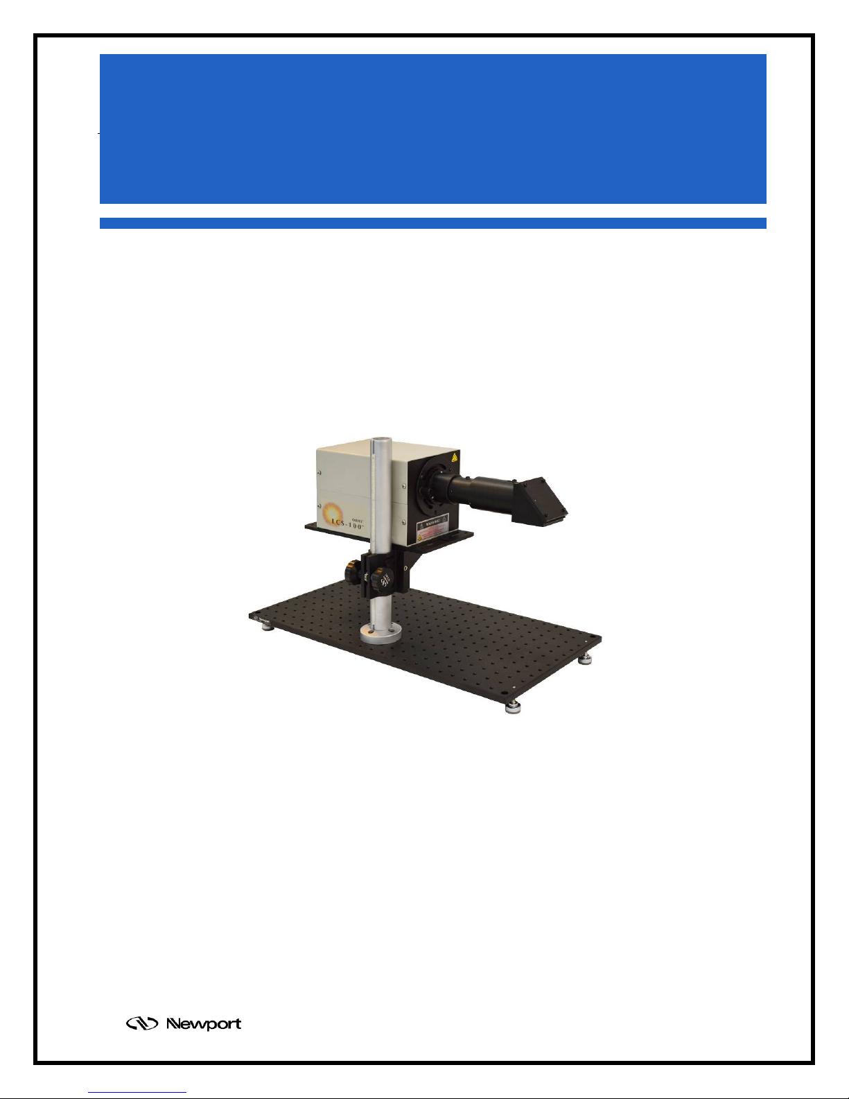
Small Area Sol1A
LCS-100
APEX Illuminators
1M-66450
94011A
94011A-ES
Family of Brands – Corion® • New Focus™ • Oriel® Instruments • Richardson Gratings™ • Spectra-
User's Manual
M94011A Rev: April 2018
Page 2

M94011A
Oriel® LCS-100TM Small Area Sol1A
TABLE OF CONTENTS
INTRODUCTION .................................................................................................................................... 4
1
2 SAFETY .................................................................................................................................................. 6
2.1 UV AND VISIBLE RADIATION ..................................................................................................... 6
2.2 LAMP EXPLOSION ...................................................................................................................... 6
2.3 OZONE ......................................................................................................................................... 7
2.4 ELECTRICAL SHOCK .................................................................................................................. 7
2.5 EMI ................................................................................................................................................ 8
2.6 HEAT ............................................................................................................................................ 8
2.7 GENERAL WARNINGS ................................................................................................................ 8
2.8 GENERAL CAUTIONS ................................................................................................................. 9
2.9 WARNING SYMBOLS .................................................................................................................. 9
3 UNPACKING AND ASSEMBLING THE SYSTEM ............................................................................... 12
3.1 MODEL 75 HEAVY DUTY MOUNTING ROD ............................................................................. 12
3.2 POST CLAMP AND ANGLE BRACKET ..................................................................................... 13
3.3 ANGLE BRACKET MOUNTING TO BOTTOM OF LCS-100TM ................................................... 13
3.4 ROD ASSEMBLY ........................................................................................................................ 14
4 FILTER INSTALLATION / REPLACEMENT ......................................................................................... 15
5 LAMP INSTALLATION / REPLACEMENT ........................................................................................... 17
5.1 ARC LAMPS ............................................................................................................................... 17
6 OPERATION ......................................................................................................................................... 21
6.1 FUSE CHANGE FOR 220VAC ................................................................................................... 21
6.2 MOUNTING OPTIONS ............................................................................................................... 22
6.3 LAMP START ............................................................................................................................. 23
6.4 SHUTTER ................................................................................................................................... 24
6.5 IRRADIANCE ADJUSTMENT ..................................................................................................... 25
7 TROUBLESHOOTING .......................................................................................................................... 26
8 SPECIFICATIONS ................................................................................................................................ 27
9 WARRANTY & SERVICE ..................................................................................................................... 30
CONTACTING ORIEL® INSTRUMENTS ........................................................................................ 30
REQUEST FOR ASSISTANCE / SERVICE ...................................................................................... 30
REPAIR SERVICE ............................................................................................................................ 31
NON-WARRANTY REPAIR .............................................................................................................. 31
WARRANTY REPAIR........................................................................................................................ 31
LOANER / DEMO MATERIAL ........................................................................................................... 32
- 2 -
Page 3

M94011A
Oriel® LCS-100TM Small Area Sol1A
LIST OF TABLES
SPECIFICATIONS of LCS-100
Typical Output Power from LCS-100
TM
Solar Simulator ..................................................................................... 27
TM
Solar Simulator ............................................................................. 27
LIST OF FIGURES
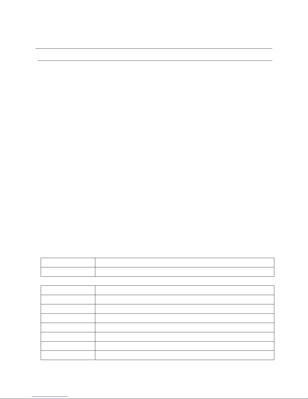
Figure 1: LCS-100TM Model 94011A shown with optional SA-12 Mount Plate............................................... 5
Figure 2: LCS-100TM Model 94011A-ES shown with optional SA-12 Mount Plate ........................................ 5
Figure 3: Model 75 Rod Mounting .............................................................................................................. 12
Figure 4: 90 Degree angle bracket to Post Clamp assembly ..................................................................... 13
Figure 5: 90 Degree angle bracket assembly to bottom of unit .................................................................. 13
Figure 6: Rod assembly ............................................................................................................................. 14
Figure 7: Filter retention thumbscrews ....................................................................................................... 15
Figure 8: Filter assembly insertion and removal ......................................................................................... 16
Figure 9: Filter assembly engagement ....................................................................................................... 16
Figure 10: Lamp cage retention cover and thumbscrew ............................................................................ 17
Figure 11: Lamp retaining clip and retaining posts ..................................................................................... 18
Figure 12: Lamp handling, insertion, and removal ..................................................................................... 18
Figure 13: Lamp seating ............................................................................................................................. 19
Figure 14: Lamp held while retaining clip engaged .................................................................................... 19
Figure 15: Lamp connector engagement ................................................................................................... 20
Figure 16: Lamp mounted properly in its cage ........................................................................................... 20
Figure 17: Fuse replacement ..................................................................................................................... 21
Figure 18: 94011A Dimensions .................................................................................................................. 22
Figure 19: 94011A-ES Dimensions ............................................................................................................ 23
Figure 20: Manual Shutter Knob ................................................................................................................ 24
Figure 21: Spectral output of LCS-100TM Solar Simulator with the AM1.5G filter ....................................... 28
Figure 22: Spectral output of LCS-100TM Solar Simulator with AM0 filter in place of AM1.5G filter ........... 28
Figure 23: Certification data from 94011A Solar Simulator showing the Class A spectral match .............. 29
- 3 -
Page 4
M94011A
Oriel® LCS-100TM Small Area Sol1A
1 INTRODUCTION
The Oriel® LCS-100TM Small Area Sol1A Series is an integrated, compact, and easy to operate Solar
Simulator.
The Oriel
®
LCS-100TM consists of:
PN 603402: light source assembly containing
o Factory-preset power supply igniter
o Lamp housing with a pre-aligned lamp mount
o Fan assembly with adaptive speed control for stable output
o Safety interlocks and thermal cutout protection
PN 90045340: mounted optics containing
o Beam homogenizer
o 90 degree beam turner, for downward, upward, and side directing
PN 81088A-LCS: AM1.5G Filter (AM0 or AM Direct filter optional accessories)
PN 6252: 100W Ozone Free Xenon lamp with integral elliptical reflector
PN 75: Heavy Duty 14” Damped Rod for Working Distance adjustment, inch and metric mount
PN 370-RC: Post Clamp Assembly
PN 90056950: Oriel
®
1.5” Series flange at input of 90 degree beam turner
PN 90-11-042 & 90-11-049: hex wrenches: 1/16”, 3/16”, respectively
Certificate of Compliance to IEC and ASTM Standards ABB rating
All that is required is mounting the adjustable mounting rod, filter and lamp, plugging in the power cord,
switching on the source and adjusting the Irradiance at the working height.
LCS-100
TM
Series Solar Simulators
94011A
94011A-ES
LCS-100
LCS-100
TM
Solar Simulator, Manual Shutter only
TM
Solar Simulator, Manual and Motorized Safety Shutter
Accessories
6252
81011-LCS
81389-LCS
SA2-11 (M-SA2-11)
SA2-12 (M-SA2-12)
Replacement 100 W Xenon lamp assembly
2” Square AM0 Filter mounted in frame
2” Square AM Direct Filter mounted in frame
12” x 12” (300 x 300mm) Solid Aluminum Plate
24” x 12” (600 x 300mm) Solid Aluminum Plate
20-22-005
91150V
PVIV-1A
LEVELER 1/4-20 X 1 Length Leveling foot for use with Inch Plate, 4 required
Reference Cell and Meter System
1 Amp I-V Measurement SourceMeter, Software and Cables
- 4 -
Page 5
M94011A
Oriel® LCS-100TM Small Area Sol1A
Figure 1: LCS-100
TM
Model 94011A shown with optional SA-12 Mount Plate
and (4) 20-22-005 Leveling Feet
Figure 2: LCS-100
TM
Model 94011A-ES shown with optional SA-12 Mount Plate
and (4) 20-22-005 Leveling Feet
- 5 -
Page 6

Oriel® LCS-100TM Small Area Sol1A
2 SAFETY
SUMMARY OF HAZARDS
The hazards encountered in the operation of these illuminator systems are:
Radiation
Lamp explosion
Ozone
Electrical shock
EMI
Heat
The interlock system is designed for your safety. Do not defeat the interlocks.
2.1 UV AND VISIBLE RADIATION
The high intensity UV and VIS radiation of the lamp can permanently damage the cornea, lens, and
retina of the eye, even causing blindness. This damage may not be immediately apparent. The deep UV
is absorbed in the cornea or eye fluids; focused UV, VIS, and NIR can damage the retina. Normal blink
reaction to visible light may not be adequate protection, and a beam of invisible UV or NIR (produced
by spectral filtering) can be most dangerous, as the blink response is not induced. UV radiation can
also cause painful sunburn, and with prolonged exposure, serious burns.
M94011A
Recommendations
1. Never look directly into the output beam from an arc lamp housing.
2. Do not look at the specular (mirror) reflection of the beam.
3. Always wear UV protective eyewear or facemask, and adequate protection for exposed areas of
skin.
2.2 LAMP EXPLOSION
When Xenon, Mercury and Mercury-Xenon arc lamps are cold, they are under several atmospheres of
pressure and may explode due to internal strains or physical abuse. When hot, all lamps are under a
pressure of many atmospheres and the possibility of violent explosion exists. Fingerprints and
other contaminants left on the lamp cause a deterioration of the envelope during operation and may
lead to lamp explosion.
Recommendations
1. Do not handle a bare arc lamp without safety goggles and adequate protection for exposed areas
of skin.
2. Wear gloves when handling a lamp. Do not touch the lamp envelope with your fingers.
3. Clean the lamp envelope thoroughly with alcohol or a dilute solution of detergent and water if it
comes in contact with skin.
- 6 -
Page 7

4. Attach a cover plate over the output port of any illuminator that will be used without the output
enclosed, before operation.
2.3 OZONE
M94011A
Oriel® LCS-100TM Small Area Sol1A
Shortwave ultraviolet radiation photolyses oxygen to produce ozone - O
concentrations of ozone can cause nasal dryness and a burning sensation in the throat, headaches,
nausea, and irritation of the mucous membranes.
A 150 W UV arc lamp can contribute more than 1 part ozone per million to the cooling air system.
This may be of little consequence in a well-ventilated area, but some people are very sensitive to
ozone and long term effects are not well documented. Noticeable symptoms for most people appear at
around 0.3 - 0.5 ppm.
Recommended maximum exposures are typically:
0.1 ppm for 8 hours exposure
2 ppm or a 2 hour exposure
Recommendations
1. Use an ozone free lamp unless you need the shortwave UV.
2. Vent the cooling air stream to atmosphere (with a low resistance vent path). Do not vent ozone
into a small, enclosed room.
3. Use an Oriel Ozone Eater
2.4 ELECTRICAL SHOCK
. Relatively low
3
TM
.
When the 94011A(-ES) is operated as intended, the interlock system and the package design
eliminate risk of electrical shock.
Be aware that a high transitory voltage is used to ignite the lamp and, before ignition, the lamp
terminals have a potential difference of up to 200 V. This voltage is dangerous. If there is any concern
about the interlock system, great care is required.
Recommendations
1. Disconnect the illuminator from the ac power mains before removing the cover or optics
assembly.
2. Keep personnel clear of all exposed terminals.
3. Make sure all connections are securely made and check the polarity before starting a lamp.
4. Do not handle lamp leads during lamp ignition.
- 7 -
Page 8
2.5 EMI
The 94011A(-ES) housing contains EMI (Electro Magnetic Interference) under normal operating
conditions. However, ignition of an arc lamp requires high voltage pulses to break the lamp down and
a high current dump (10’s of Amps discharge) to sustain the arc. Arc lamp ignition creates significant
electromagnetic energy. The high level of EMI integrity of the source contains most of this transient
energy, but additional earthing, careful cable routing, and EMI shielding may be necessary to protect
sensitive digital circuitry from these events.
Recommendations
1. Start the arc lamp before powering nearby computer systems.
2. Keep the computer at least 2 feet away from the ignitor/power supply.
3. Use a different outlet and line for the computer and ignitor/power supply.
2.6 HEAT
The lamps become very hot during operation, and may remain so for many minutes after being shut
off.
M94011A
Oriel® LCS-100TM Small Area Sol1A
Recommendations
1. The fan will remain On for 2 minutes after lamp turn off, after which the power cord can be
removed. Wait at least 10 minutes after turning off the lamp before removing the housing top
cover to access the lamp.
2. Approach the lamp as if it were hot under any circumstances.
3. Allow at least 2 inches of clearance near the fan opening and ventilation slots for adequate
cooling of the lamp and power supply.
2.7 GENERAL WARNINGS
Observe these general warnings when operating or servicing this equipment:
Heed all warnings on the unit and in the operating instructions.
Do not use this equipment in or near water.
This equipment is grounded through the grounding conductor of the power cord.
Route power cords and other cables so they are not likely to be damaged.
Disconnect power before cleaning the equipment. Do not use liquid or aerosol cleaners; use
only a damp lint-free cloth.
Lockout all electrical power sources before servicing the equipment.
- 8 -
Page 9
To avoid fire hazard, use only the specified fuse(s) with the correct type number, voltage and
current ratings as referenced in the appropriate locations in the service instructions or on the
equipment. Only qualified service personnel should replace fuses.
To avoid explosion, do not operate this equipment in an explosive atmosphere.
Qualified service personnel should perform safety checks after any service.
2.8 GENERAL CAUTIONS
Observe these cautions when operating or servicing this equipment:
If this equipment is used in a manner not specified in this manual, the protection provided by this
equipment may be impaired.
Do not block ventilation openings.
Do not position this product in such a manner that would make it difficult to disconnect the power
cord.
Use only the specified replacement parts.
Follow precautions for static sensitive devices when handling this equipment.
This product should only be powered as described in the manual.
Aside from the lamp and filter holder, there are no operator serviceable parts inside - arc lamp
maintenance is to be performed by a responsible body that has read, understands and follows the
precautions in this manual.
To prevent damage to the equipment, read the instructions in the equipment manual for proper
input voltage.
M94011A
Oriel® LCS-100TM Small Area Sol1A
2.9 WARNING SYMBOLS
The following terms and symbols are used in this documentation and also appear on the LCS-100
Small area Sol1A where safety-related issues occur.
General Warning or Caution
The Exclamation Symbol in the figure above appears in Warning and Caution content throughout
this document. This symbol designates a matter in which personal injury or damage to the
equipment is possible.
Electric Shock
- 9 -
TM
Page 10
M94011A
Oriel® LCS-100TM Small Area Sol1A
The Electrical Shock Symbol in the figure above appears throughout this manual. This symbol
indicates a hazard arising from dangerous voltage. Any mishandling could result in irreparable
damage to the equipment, and personal injury or death.
Caution, Hot Surface
The Caution, Hot Surface Symbol in the figure above appears on the 94011A(-ES) and throughout
this manual. This symbol indicates a burn hazard arising from elevated temperatures.
European Union CE Mark
The presence of the CE Mark on Newport Corporation equipment means that it has been
designed, tested and certified as complying with all applicable European Union (CE) regulations
and recommendations.
Alternating voltage symbol
This international symbol designates an alternating voltage or current.
Waste Electrical and Electronic Equipment (WEEE)
This symbol on the product or on its packaging indicates that this product must not be disposed of
with regular waste. Instead, it is the user responsibility to dispose of waste equipment according to
the local laws. The separate collection and recycling of the waste equipment at the time of
disposal will help to conserve natural resources and ensure that it is recycled in a manner that
protects human health and the environment. For information about where the user can drop off the
waste equipment for recycling, please contact your local Newport Corporation representative.
Protective Conductor Terminal
The protective conductor terminal symbol in the above figure identifies the location of the bonding
terminal inside the unit, which is bonded to conductive accessible parts of the enclosure for safety
purposes.
ON
The ON symbol in the above figure indicates the ON position of the power switch, which is located
- 10 -
Page 11

M94011A
Oriel® LCS-100TM Small Area Sol1A
above the power cord.
OFF
The OFF symbol in the above figure indicates the OFF position of the power switch, which is
located above the power cord.
- 11 -
Page 12

M94011A
Oriel® LCS-100TM Small Area Sol1A
3 UNP ACKING AND ASSEMBLING THE SYSTEM
The optics beam turner output port was covered for its protection during transportation. Before operating,
the plastic protector must be removed. Save the plastic protector in case you need to store or transport
the unit in the future.
The preferred mounting configuration for the illuminator is mounted to an optical table or breadboard type of
mount plate using the Newport Model 75 Mounting Rod. This rod has 4 mount holes that are spaced to be
compatible with inch and metric (25mm) holes. This rod provides the quickest approach to fine-tune the height
while maintaining rotational and planar alignment with the work plane. For additional mounting configurations,
see Section 6.3.
3.1 MODEL 75 HEAVY DUTY MOUNTING ROD
Remove the Newport Model 75 Mounting Rod from its packaging. Use the (4) supplied 1/4 - 20 x 5/8”
or (4) M6 x 16 screws to mount the Rod to a suitable location on an optical table or optional
baseplate. Make sure the nylon rack is facing the operator position.
Figure 3: Model 75 Rod Mounting
- 12 -
Page 13

3.2 POST CLAMP AND ANGLE BRACKET
Remove the Newport Model 370-RC Post Clamp and 360-90 90 Degree Angle Bracket from their
packaging. Use the (4) supplied 1/4 - 20 x 5/8” screws, (4) split lock washers, and (4) flat washers to
attach them as shown. The knob with the model number on it will be used to loosen the clamp. This
works better for a right-handed person when it is on the right side, assembled as shown.
M94011A
Oriel® LCS-100TM Small Area Sol1A
Figure 4: 90 Degree angle bracket to Post Clamp assembly
3.3 ANGLE BRACKET MOUNTING TO BOTTOM OF LCS-100
Turn the LCS-100
TM
unit upside down on a clean non-marring surface. Use the supplied 1/4 - 20 x
7/8” screws, 1 split lock washer, and 1 flat washer to attach them as shown. Note that if the user
prefers, it can be mounted on the opposite side from that which is shown, if the nickel plated flat head
screw is replaced by one of the 1/4 - 20 x 7/8” screws.
TM
Figure 5: 90 Degree angle bracket assembly to bottom of unit
- 13 -
Page 14

3.4 ROD ASSEMBLY
Loosen the Model 370-RC Post Clamp. Hold the unit on the bottom in the area of the bracket near its
center of mass. Slide it down the Model 75 Rod so that the rack lines up with the gear. Tighten the
clamp knob.
M94011A
Oriel® LCS-100TM Small Area Sol1A
Figure 6: Rod assembly
- 14 -
Page 15

M94011A
Oriel® LCS-100TM Small Area Sol1A
4 FILTER INSTALLATION / REPLACEMENT
The 94011A(-ES) solar simulator includes an AM1.5G spectral correction filter. It shapes the light output to
closely match the total (direct and diffuse) solar spectrum on the Earth’s surface, at a zenith angle of 48.2°
(ASTM 892). This provides a Class A irradiance spectrum suitable for Photovoltaic cell testing.
The filter is shipped in its own case. Note that the solar simulator should not be transported with the filter in
place. Save this case for storage of the filter.
The coated side is mounted on the side with the screw heads showing, and must face the lamp, as shown.
Installation and replacement
TM
1. Disconnect the LCS-100
2. Remove the LCS-100
or remove the bottom 4 Phillips head screws. Lift the top cover up straight to remove.
3. It is easier to remove and install the filter assembly without a lamp installed, and can avoid
damage to the filter and lamp. This is recommended.
4. Remove the two thumbscrews as shown in Figure 7, and set aside.
from the AC mains.
TM
top cover by removing the top 4 Phillips head screws only . Do not loosen
5. If a filter assembly is in place to be removed, slide it off the two retaining studs while grasping it as
shown in Figure 8.
6. Lift it out slowly, being careful that the filter does not get scratched or dropped. Place it into
protective packaging.
Figure 7: Filter retention thumbscrews
- 15 -
Page 16

M94011A
Oriel® LCS-100TM Small Area Sol1A
Figure 8: Filter assembly insertion and removal
7. If a filter assembly is to be installed, remove it from its packaging and orient it so that it is angled
away from the lamp toward its bottom as shown in Figure 8.
8. Lower it slowly into place with a slight tilt to engage one of the holes with its corresponding
retaining stud. Pivot the filter assembly to engage the other retaining stud as shown in Figure 9.
Figure 9: Filter assembly engagement
9. Replace the two thumbscrews, as shown in Figure 7.
10. If you want to install a lamp, proceed to Section 5 for instructions.
11. Install the LCS-100
down. Replace the top 4 Phillips head screws, tightening securely.
TM
top cover with the grooved edge engaging the front panel, sliding it straight
- 16 -
Page 17

5 LAMP INSTALLATION / REPLACEMENT
5.1 ARC LAMPS
Please review the safety precautions in sections:
2.2 LAMP EXPLOSION
2.4 ELECTRICAL SHOCK
2.6 HEAT
2.7 GENERAL WARNINGS
2.8 GENERAL CAUTIONS
Handle the lamp carefully. Do not put significant stress on the lamp envelope or connecting wires.
Gloves and eye protection are recommended to be worn when handling an arc lamp.
The following are instructions for the responsible body that has read and follows all warnings stated in
section II Safety when performing these maintenance activities. The responsible body is also
responsible for ensuring that operators are adequately trained in the safe operation of this equipment.
M94011A
Oriel® LCS-100TM Small Area Sol1A
Installation and replacement
TM
1. Disconnect the LCS-100
2. Remove the LCS-100
from the AC mains.
TM
top cover by removing only the top 4 Phillips head screws. Do not loosen
or remove the bottom 4 Phillips head screws.
3. Remove the lamp cage connector retention cover by removing the thumbscrew and set aside, as
shown in Figure 10.
Figure 10: Lamp cage retention cover and thumbscrew
4. If an old lamp is in place, make sure it has cooled at least 10 minutes. Disconnect the lamp
connector from the power supply connector, being careful not to stress or excessively pull on the
wires at the lamp ends.
5. Gently squeeze together the handles of the lamp retaining clip to disengage from the grooved
- 17 -
Page 18

M94011A
Oriel® LCS-100TM Small Area Sol1A
retaining posts, and let it pivot back to its open position, as shown in Figure 11.
Retaining posts Retaining Clip
Figure 11: Lamp retaining clip and retaining posts
6. If an old lamp is in place, rotate it slightly and tilt it back so that the anode lead wire clears the
lamp seating plate, then lift it out of the lamp cage slowly , and set it down gently . For best control,
handle the lamp only by the ceramic mounting flange at the base of the reflector.
7. Remove the new lamp from its packaging. Grasp it by the ceramic base with the Anode wire
oriented upward for best maneuvering, as shown in Figure 12.
Figure 12: Lamp handling, insertion, and removal
8. Gently lower the lamp into the lamp cage. Rotate it slightly and tilt it back so that the anode lead
wire clears the lamp seating plate. Guide the reflector rim into the recessed lamp seat, using the
two white pegs as rests for guiding the lamp into place. Make sure the Anode wire is centered
within the cutout at the top of the lamp seating plate, as shown in Figure 13 and 14.
- 18 -
Page 19

M94011A
Oriel® LCS-100TM Small Area Sol1A
Figure 13: Lamp seating
9. Engage the lamp retaining clip over the back side of the reflector rim on either side, then within
the grooved retaining post above it. Engage the other side similarly , so that the clip sits within the
groove of the retaining post above it, as shown in Figure 14.
Figure 14: Lamp held while retaining clip engaged
10. While sliding the power supply connector into the cutout in the rear of the lamp cage, connect it to
the lamp connector, being careful not to stress or excessively pull on the wires at the lamp ends,
as shown in Figure 15. Note that the connector is keyed so that it may only engage with the
proper polarity.
- 19 -
Page 20

M94011A
Oriel® LCS-100TM Small Area Sol1A
Top
Figure 15: Lamp connector engagement
11. Replace the lamp cage connector retention cover and screw on the thumbscrew securely.
12. If bare skin has contacted the lamp bulb be sure to cleanse the envelope thoroughly (Section 2.2).
Fingerprints – or any contaminant – can cause deterioration of the envelope during lamp
operation and could lead to premature lamp failure or lamp explosion.
TM
13. Replace the LCS-100
top cover with the grooved edge engaging the front panel, sliding it
straight down. Replace the top 4 Phillips head screws, tightening securely.
Figure 16: Lamp mounted properly in its cage
- 20 -
Page 21

6 OPERATION
6.1 FUSE CHANGE FOR 220VAC
There are 2 fuses factory installed in the power cord jack at the rear panel, which are for 100 –
120VAC (nominal) operation. They are 1.5A type T (slo-blo).
For 200 – 240V AC (nominal) operation, you must replace these with the 0.8A type T (slo-blo) fuses
that are supplied in a bag shipped with the unit, as follows:
M94011A
Oriel® LCS-100TM Small Area Sol1A
1. Unplug the LCS-100
TM
.
2. Use your finger or a small flat bladed screwdriver to slide out the fuse holder.
3. Flip down the outer wall a bit, which will raise the leading edge of the 2 fuses.
4. You may access the fuses with the aid of the screwdriver.
5. Replace them with the 0.8A type T (slo-blo) fuses that are supplied, flip the wall up and slide it into
place until it is flush with the connector.
Figure 17: Fuse replacement
- 21 -
Page 22

6.2 MOUNTING OPTIONS
The preferred mounting configuration for the illuminator is mounted to an optical table or breadboard
type of mount plate using the Newport Model 75 Mounting Rod. This rod has 4 mount holes that are
spaced to be compatible with inch and metric (25mm) holes. This rod provides the quickest approach
to fine-tune the height while maintaining rotational and planar alignment with the work plane.
The 6” x 12” (152.4 x 304.8mm) integral baseplate has 1/4 - 20 mounting holes at the corners, spaced
5” x 11”. These can be used to mount fixed length posts such as type SP-6, which may then be
mounted within post holders such as type VPH-6, to provide height adjustment. If fixed posts are
used, then it is recommended to adjust the target device (test cell) height, to provide the Irradiance
adjustment. See Figures 18 and 19 for mounting dimension detail drawings.
For upward or side directing applications, the integral baseplate can be bolted to an inch or metric
table. Use the 1/16 hex wrench to loosen and turn the 90
side of its housing to square it up before retightening. For forward directing of the beam, the beam
turner may be removed (working distance from the tube end reference plane will then be 2.5” more). A
71260 Filter Holder may be used at this optical location for additional external filters. Use extra care in
these configurations to prevent eye damage.
For proper operation, the 94011A(-ES) is to be mounted in a preferred orientation such that its
electrode axis is within 15
airflow and thermal control.
° of horizontal. This is important for the lamp life, as well as for proper
M94011A
Oriel® LCS-100TM Small Area Sol1A
° beam turner. Use a 90° block against the
Figure 18: 94011A Dimensions
W.D.
- 22 -
Page 23

M94011A
Oriel® LCS-100TM Small Area Sol1A
Do not position the 94011A such that it is difficult to operate the power switch or remove the power
cord.
W.D.
Figure 19: 94011A-ES Dimensions
6.3 LAMP START
1. Install the desired filter in the filter holder. See Section 4 for detailed instructions.
2. Install the lamp. See Section 5 for detailed instructions.
3. Connect the 94011A(-ES) to the AC mains.
4. Review the safety precautions of Section 2, especially Section 2.2. Make sure that the output
beam is positioned as desired and all personnel are wearing appropriate safety apparel.
5. Turn on the power switch. The lamp will start within a few seconds. The fan will start in about 6
seconds.
6. The light output will be stable in less than 10 minutes.
- 23 -
Page 24

6.4 SHUTTER
Open and close the shutter with the knurled knob (clockwise is open).
Manual Shutter
M94011A
Oriel® LCS-100TM Small Area Sol1A
Figure 20: Manual Shutter Knob
The 94011A-ES additionally has a 71446 electronic safety shutter, complete with control box,
interconnecting cable, and 71449 cable for controlling the shutter from a Keithley 2400 series
SourceMeter when used in conjunction with PVIV 2.0 software. Refer to the M71445 and MPVIV
Manuals for additional information.
- 24 -
Page 25

6.5 IRRADIANCE ADJUSTMENT
There is one method of adjusting the irradiance. The lamp should be warmed up at least 10 minutes
to be stable, and a detector such as the 91150V should be placed in the intended working plane to
monitor the output adjustment.
Working Distance
Working Distance (W .D.) is defined as the distance from the output port bottom surface to the t arget
plane. Since the output beam is slightly divergent, adjusting the W.D. has an inverse effect on the
Irradiance. The LCS-100
TM
has been factory adjusted for best uniformity at the specified W.D. found
in section 8, where it is certified. However, the uniformity is generally within Class B for W.D. within
the range of 6 to 10 inches.
As the lamp ages, the W.D. will need to be reduced to maintain 1 SUN output. This is accomplished
by means of the mounting rod or target device height adjustment. The mounting rod is adjusted by
the following means:
1. Grasp both of the mounting rod knobs, one in each hand.
2. Rotate the locking knob counterclockwise. This is the knob with the Model number 370-RC
engraved, generally on the right as shown in the photos.
M94011A
Oriel® LCS-100TM Small Area Sol1A
3. To raise the LCS-100
TM
, place that hand under the angle bracket mounted to the integral
baseplate, and exert upward force while rotating the other knob counterclockwise. This knob has
a gear that engages with the rack on the rod to move it up.
TM
4. To lower the LCS-100
, slowly rotate the other knob clockwise. This knob has a gear that
engages with the rack on the rod to move it down.
5. Rotate the locking knob clockwise to secure the clamp around the rod.
- 25 -
Page 26

Oriel® LCS-100TM Small Area Sol1A
7 TROUBLESHOOTING
PROBLEM POSSIBLE CAUSE ACTION
Check that the power switch is turned ON
No power – blown fuse or power
supply
and the orange light in the switch is lit
brightly. Check that power cord is fully
seated.
M94011A
Lamp not properly installed
Lamp does not start
Defective or marginal lamp
Follow the lamp installation procedure
carefully. Connections should be firm.
Repeat ignition sequence.
Check that lamp has a starter wire.
Replace lamp.
Old lamp Replace lamp.
Lamp not installed Install lamp.
Insulation breakdown Contact Oriel Instruments.
Interlock fault
Ensure that the top cover is in place.
Consult Oriel Instruments.
Defective lamp Replace lamp.
Lamp explodes
Old lamp
Contaminated lamp envelope
Replace lamp when stability becomes
erratic, or output is < 60% of original.
Do not handle inside of lamp reflector or
lamp. Clean lamp if needed.
Air vents blocked Needs > 1” clearance, < 40°C ambient air
Shutter does
not open
Damaged manual shutter,
shutter mechanically jammed
Defective 71446 shutter drive
circuit
Repair or replace shutter assembly.
Contact Oriel Instruments.
Dirty optics Clean optics.
Loss of power
in output beam
Damaged optics Replace optical assemblies.
Old lamp Replace lamp.
Loss of
beam uniformity
Dirty optics Clean optics.
Output unstable Old lamp Replace lamp.
- 26 -
Page 27

Oriel® LCS-100TM Small Area Sol1A
8 SPECIFICATIONS
SPECIFICATIONS of LCS-100
Beam Size 1.5 X 1.5 inch (38mm X 38mm)
Spectral Match Classification A (IEC 60904-9 2007)
Beam Non-uniformity B (IEC 60904-9 2007)
Temporal Instability B (IEC 60904-9 2007)
Collimation Angle < 6°
Working Distance 7” ± 1” ( 203 ± 51mm)
Irradiance Adjustment Iris: + 0% - 40%
Light ripple: <0.5% rms
TM
Solar Simulator
A (ASTM E927 – 10)
B (ASTM E927 – 10)
B (ASTM E927 -10)
Height: ~0.18 SUN / inch
M94011A
Line regulation: 0.03%
Operating Environment: 5°C to 40°C; <80% RH non-condensing; <3000m Altitude;
Indoor Use only; Installation Category II; Pollution degree 2
Lamp Type 100W Ozone – Free Xenon
Lamp Life ~1000 Hours typical
Input Power 100 – 240 VAC, 50 / 60 Hz, 130W
Fuses: 1.5A T (slo-blo), 250V for 100 / 120 VAC
0.8A T (slo-blo), 250V for 200 / 240 VAC
Typical Output Power from LCS-100
TM
Solar Simulator
Working Distance from the
output flange (inches)
Readings with AM0
Filter (mW/cm2)
Readings with AM1.5G
Filter (mW/cm2)
6 247 161
7 184 119
8 151 100
9 126 82
10 105 69
- 27 -
Page 28

M94011A
Oriel® LCS-100TM Small Area Sol1A
Figure 21: Spectral output of LCS-100
TM
Solar Simulator with the AM1.5G filter
Figure 22: Spectral output of LCS-100
TM
Solar Simulator with AM0 filter in place of AM1.5G filter
- 28 -
Page 29

M94011A
Oriel® LCS-100TM Small Area Sol1A
94011A Spectral Match
26%
24%
22%
20%
18%
16%
14%
% Total Irradi ance
12%
10%
8%
400 500 600 700 800 900 1000 1100
Wavelengt h ( nm)
Ideal Match
Upper Limit
Lower Limit
94011A
Figure 23: Certification data from 94011A Solar Simulator showing the Class A spectral match
- 29 -
Page 30

Oriel® LCS-100TM Small Area Sol1A
9 WARRANTY & SERVICE
CONTACTING ORIEL® INSTRUMENTS
REQUEST FOR ASSISTANCE / SERVICE
Is the system used for manufacturing or research and development?
What was the state of the system right before the problem?
Had this problem occurred before? If so, when and how frequently?
Can the system continue to operate with this problem, or is it non-operational?
Were there any differences in the application or environment before the problem occurred?
®
Instruments belongs to Newport Corporation's family of brands. Thanks to a steadfast
Oriel
commitment to quality, innovation, hard work and customer care, Newport is trusted the world over as
the complete source for all photonics and laser technology and equipment.
Founded in 1969, Newport is a pioneering single-source solutions provider of laser and photonics
components to the leaders in scientific research, life and health sciences, photovoltaics,
microelectronics, industrial manufacturing and homeland security markets.
Newport Corporation proudly serves customers across Canada, Europe, Asia and the United States
through 9 international subsidiaries and 24 sales offices worldwide. Every year, the Newport Resource
catalog is hailed as the premier sourcebook for those in need of advanced technology products and
services. It is available by mail request or through Newport's website. The website is where one will
find product updates, interactive demonstrations, specification charts and more.
To obtain information regarding sales, technical support or factory service, United States and Canadian
customers should contact Oriel
Newport Corp.- Oriel
®
Instruments directly.
®
Instruments
31950 E. Frontage Rd.
Bozeman, MT 59715 USA
Telephone: (877) 835-9620(toll-free in United States)
(949) 863-3144
Fax: (949) 253-1680
Sales: orielPV.sales@newport.com
Technical assistance or repair service: orielPV.service@newport.com
Customers outside of the United States must contact their regional representative for all sales,
technical support and service inquiries. A list of worldwide representatives can be found on Oriel's
website: http://www.newport.com/oriel.
Please have the following information available when requesting assistance or service:
1. Contact information for the owner of the product.
2. Instrument model number (located on the product label).
3. Product serial number and date of manufacture (located on the product label).
4. Description of the problem.
To help Oriel's Technical Support Representatives diagnose the problem, please note the
following:
M94011A
- 30 -
Page 31

REPAIR SERVICE
This section contains information regarding factory service for this product. The user should not
attempt any maintenance or service of the system beyond the procedures outlined in this manual. This
product contains no user serviceable parts other than what is noted in this manual. Any problem that
cannot be resolved should be referred to Oriel
If the instrument needs to be returned for service, a Return Material Authorization (RMA) number must
be obtained prior to shipment to Oriel
shipping container and the package documents.
Return the product to Oriel® Instruments, freight prepaid, clearly marked with the RMA number and it
will either be repaired or replaced it at Oriel
®
is not responsible for damage occurring in transit. The Owner of the product bears all risk of loss
Oriel
or damage to the returned Products until delivery at Oriel
product damage once it has left the facility after repair or replacement has been completed.
®
Oriel
is not obligated to accept products returned without an RMA number. Any return shipment
received by Oriel® without an RMA number may be reshipped by Newport, freight collect, to the Owner
of the product.
NON-WARRANTY REPAIR
For Products returned for repair that are not covered under warranty, Newport's standard repair
charges shall be applicable in addition to all shipping expenses. Unless otherwise stated in
Newport's repair quote, any such out-of-warranty repairs are warranted for ninety (90) days from
date of shipment of the repaired Product.
M94011A
Oriel® LCS-100TM Small Area Sol1A
®
Instruments.
®
Instruments. This RMA number must appear on both the
®
's discretion.
®
's facility. Oriel® is not responsible for
®
Oriel
will charge an evaluation fee to examine the product and determine the most appropriate
course of action. Payment information must be obtained prior to having an RMA number assigned.
Customers may use a valid credit card, and those who have an existing account with Newport
Corporation may use a purchase order.
When the evaluation had been completed, the owner of the product will be contacted and notified
of the final cost to repair or replace the item. If the decision is made to not proceed with the repair,
only the evaluation fee will be billed. If authorization to perform the repair or provide a replacement
is obtained, the evaluation fee will be applied to the final cost. A revised purchase order must be
submitted for the final cost. If paying by credit card, written authorization must be provided that will
allow the full repair cost to be charged to the card.
WARRANTY REPAIR
If there are any defects in material or workmanship or a failure to meet specifications, notify Oriel®
Instruments promptly, prior to the expiration of the warranty.
Except as otherwise expressly stated in Oriel
written guarantee for any of the Products, Oriel
with respect to each Product or component type (the "Warranty Period"), the Products sold hereunder
will be free from defects in material and workmanship, and will conform to the applicable specifications,
under normal use and service when correctly installed and maintained. Oriel
®
's quote or in the current operating manual or other
®
warrants that, for the period of time set forth below
®
shall repair or replace, at
- 31 -
Page 32

Oriel® LCS-100TM Small Area Sol1A
®
Oriel
's sole option, any defective or nonconforming Product or part thereof which is returned at
Buyer's expense to Oriel® facility, provided, that Buyer notifies Oriel
®
in writing promptly after
discovery of the defect or nonconformity and within the Warranty Period. Products may only be
returned by Buyer when accompanied by a return material authorization number ("RMA number")
issued by Oriel
occurring in transit or obligated to accept Products returned for warranty repair without an RMA
number. Buyer bears all risk of loss or damage to the Products until delivery at Oriel
®
, with freight prepaid by Buyer. Oriel® shall not be responsible for any damage
®
's facility. Oriel®
shall pay for shipment back to Buyer for Products repaired under warranty.
WARRANTY PERIOD
All Products (except consumables such as lamps, filters, etc) described here are warranted for a period
of twelve (12) months from the date of shipment or 3000 hours of operation, whichever comes first.
Lamps, gratings, optical filters and other consumables / spare parts (whether sold as separate
Products or constituting components of other Products) are warranted for a period of ninety (90) days
from the date of shipment.
WARRANTY EXCLUSIONS
The above warranty does not apply to Products which are (a) repaired, modified or altered by any party
other than Oriel
®
; (b) used in conjunction with equipment not provided or authorized by Oriel® ; (c)
subjected to unusual physical, thermal, or electrical stress, improper installation, misuse, abuse,
accident or negligence in use, storage, transportation or handling, alteration, or tampering, or (d)
considered a consumable item or an item requiring repair or replacement due to normal wear and tear.
DISCLAIMER OF WARRANTIES; EXCLUSIVE REMEDY
THE FOREGOING WARRANTY IS EXCLUSIVE AND IN LIEU OF ALL OTHER WARRANTIES.
EXCEPT AS EXPRESSLY PROVIDED HEREIN, ORIEL
®
MAKES NO WARRANTIES, EITHER
EXPRESS OR IMPLIED, EITHER IN FACT OR BY OPERATION OF LAW, STATUTORY OR
OTHERWISE, REGARDING THE PRODUCTS, SOFTWARE OR SERVICES. NEWPORT
EXPRESSLY DISCLAIMS ANY IMPLIED WARRANTIES OF MERCHANTABILITY OR FITNESS FOR
A PARTICULAR PURPOSE FOR THE PRODUCTS, SOFTWARE OR SERVICES. THE
OBLIGATIONS OF ORIEL® SET FORTH IN THIS SECTION SHALL BE ORIEL'S SOLE LIABILITY,
AND BUYER'S SOLE REMEDY, FOR BREACH OF THE FOREGOING WARRANTY. Representations
and warranties made by any person including distributors, dealers and representatives of Oriel
Newport Corporation which are inconsistent or in conflict with the terms of this warranty shall not be
binding on Oriel
®
unless reduced to writing and approved by an expressly an authorized officer of
Newport.
LOANER / DEMO MATERIAL
Persons receiving goods for demonstrations or temporary use or in any manner in which title is not
transferred from Newport shall assume full responsibility for any and all damage while in their care,
custody and control. If damage occurs, unrelated to the proper and warranted use and
performance of the goods, recipient of the goods accepts full responsibility for restoring the goods
to their original condition upon delivery, and for assuming all costs and charges.
First printing 2013 © 2013 by Newport Corporation, Irvine, CA. All rights reserved.
No part of this manual may be reproduced or copied without the prior written approval of Newport Corporation.
This manual has been provided for information only and product specifications are subject to change without notice.
Any change will be reflected in future printings.
Newport Corporation 1791 Deere Avenue Irvine, CA, 92606 USA
M94011A
®
/
- 32 -
 Loading...