

Page 1
ONE-XY Series
G
U
A
R
A
N
T
E
E
D
S
P
E
C
I
F
I
C
A
T
I
O
N
S
Integrated XY
Linear Motor Stages
USER’S MANUAL
Page 2

ONE-XY Series Integrated XY Linear Motor Stages
Newport Corporation warrants this product to be free from defects in
material and workmanship for a period of 1 year from the date of
shipment. If found to be defective during the warranty period, the product
will either be repaired or replaced at Newport’s discretion.
To exercise this warranty, write or call your local Newport representative,
or contact Newport headquarters in Irvine, California. You will be given
prompt assistance and return instructions. Send the instrument,
transportation prepaid, to the indicated service facility. Repairs will be
made and the instrument returned, transportation prepaid. Repaired
products are warranted for the balance of the original warranty period, or
at least 90 days.
Limitation of Warranty
This warranty does not apply to defects resulting from modification or
misuse of any product or part.
This warranty is in lieu of all other warranties, expressed or implied,
including any implied warranty of merchantability or fitness for a
particular use. Newport Corporation shall not be liable for any indirect,
special, or consequential damages.
by Newport Corporation, Irvine, CA. All rights reserved.
Original instructions.
No part of this document may be reproduced or copied without the prior
written approval of Newport Corporation. This document is provided for
information o nl y, and pro du ct specifications are subject to change without
notice. Any change will be reflected in future publishings.
CAUTION
Warranty does not apply to damages resulting from:
• Incorrect usage:
– Load on the stage greater than maximum specified load.
– Carriage speed higher than specified speed.
–Improper grounding.
¬ Connectors must be properly secured.
¬ When the load on the stage represents an electrical risk, it must
be connected to ground.
– Excessive or improper cantilever loads.
• Modification of the stage or any part thereof.
CAUTION
Please return equipment in
the original (or equivalent)
packing.
You will be responsible for
damage incurred from
inadequate packaging if the
original packaging is not
used.
Warranty
EDH0351En1012 — 10/18 ii
© 2018
Page 3

ONE-XY Series Integrated XY Linear Motor Stages
Table of Contents
Warranty .................................................................................................................ii
EC Declaration of Conformity...............................................................................v
Definitions and Symbols.......................................................................................vi
Warnings ...............................................................................................................vii
Caution ...................................................................................................................ix
1.0 — Introduction.................................................................................1
2.0 — Description ...................................................................................2
2.1 Design Details ............................................................................................2
3.0 — Characteristics............................................................................3
3.1 Definitions ..................................................................................................3
3.2 Mechanical Specifications .......................................................................4
3.3 Hard Stop ...................................................................................................4
3.4 Load Characteristics and Stiffness .........................................................4
4.0 — Drive and Motor.........................................................................5
4.1 Motor characteristics (Direct Drive Brushless Motor) ........................5
4.2 Command Signals ......................................................................................5
4.3 Sensor Positions........................................................................................5
4.4 Position Feedback Signals........................................................................6
4.5 Pinouts........................................................................................................6
Motor (SUB-D9M Connector)...................................................................6
Encoder and End-of-Runs (SUB-D15M Connector) ...............................7
4.6 ONE-XY Cable Wiring................................................................................7
5.0 — Stage Installation.......................................................................8
5.1 Unpacking ..................................................................................................8
5.2 Mounting Conditions ................................................................................9
6.0 — Connection to Newport Controllers ..............................10
6.1 Warnings on Controllers ........................................................................10
6.2 Connection ...............................................................................................11
6.3 Cables .......................................................................................................11
7.0 — Connection to Non-Newport Controllers ....................12
8.0 — Dimensions.................................................................................13
iii EDH0351En1012 — 10/18
Page 4

ONE-XY Series Integrated XY Linear Motor Stages
9.0 — Maintenance ..............................................................................14
9.1 Maintenance ............................................................................................14
9.2 Repair .......................................................................................................14
9.3 Calibration ...............................................................................................14
Service Form .........................................................................................................15
EDH0351En1012 — 10/18 iv
Page 5
ONE-XY Series Integrated XY Linear Motor Stages
ONE-XY
Year mark affixed: 2015
EU Declaration of Conformity
The manufacturer:
Newport Corp.
1791 Deere Avenue
Irvine, CA 92606 - USA
Hereby declares that the product:
Description: " ONE-XY "
Function: Integrated XY Linear Motor Stage
Type of equipment: Special Purpose Laboratory Equipment Consisting of 2 Devices,
an X & Y Axis Linear Motorized Stage and a CE Compliant Programmable Controller
with Interconnect Cable
– complies with all the relevant provisions of the Directive 2014/30/EU relating to electromagnetic compatibility (EMC).
– complies with all the relevant provisions of the Directive 2006/95/EC relating to electrical
equipment designed for use within certain voltage limits (Low Voltage).
– complies by exemption granted to test, Measurement and Control equipment with all the
relevant provisions of the Directive 2011/65/EU relating to the restriction of the use of certain
hazardous substances in electrical and electronic equipment (RoHS2).
– was designed and built in accordance with the following harmonised standards:
EN 61326-1:2013 « Electrical equipment for measurement, control and laboratory
use – EMC requirements – Part 1: General requirements »
EN 61010-1:2010 « Safety requirements for electrical equipment for measurement,
control and laboratory use – Part 1: General requirements »
EN 55011:2009 Classe A
– was designed and built in accordance with the following other standards:
EN 61000-3-2
EN 61000-3-3
EN 61000-4-2
EN 61000-4-3
EN 61000-4-4
EN 61000-4-5
EN 61000-4-6
EN 61000-4-8
EN 61000-4-11
EN 62311
Date : 22/07/2015
Dominique DEVIDAL
Quality Director
MICRO-CONTROLE Spectra-Physics
Zone Industrielle
F-45340 Beaune La Rolande, France
DC2-EN rev:A
EC Declaration of Conformity
v EDH0351En1012 — 10/18
Page 6
ONE-XY Series Integrated XY Linear Motor Stages
The following terms and symbols are used in this documentation and also
appear on the product where safety-related issues occur.
General Warning or Caution
The exclamation symbol may appear in warning and caution tables in this
document. This symbol designates an area where personal injury or
damage to the equipment is possible.
The following are definitions of the Warnings, Cautions and Notes that may
be used in this manual to call attention to important information regarding
personal safety, safety and preservation of the equipment, or important
tips.
WA RN IN G
Warning indicates a potentially dangerous situation which can result in
bodily harm or death.
CAUTION
Caution indicates a potentially hazardous situation which can result in
damage to product or equipment.
NOTE
Note indicates additional information that must be considered by the
user or operator.
European Union CE Mark
The presence of the CE Mark on Newport Corporation equipment means
that it has been designed, tested and certified as complying with all
applicable European Union (CE) regulations and recommendations.
Warnings and Cautions
ATTENTI O N
This stage is a Class A device. In a residential environment, this device
can cause electromagnetic interference. In this case, suitable measures
must be taken by the user.
Definitions and Symbols
EDH0351En1012 — 10/18 vi
Page 7

ONE-XY Series Integrated XY Linear Motor Stages
WA RN IN G
The motion of objects of all types carries potential risks for operators.
Ensure the protection of operators by prohibiting access to the dangerous
area and by informing the personnel of the potential risks involved.
WA RN IN G
The magnetic channel included in this device has the potential to disrupt
pacemakers. Consequently, it is recommended that individuals maintain a
distance of 1 meter or more from the stage as a precautionary measure.
WA RN IN G
Do not use this stage when its motor is emitting smoke or is unusually
hot to the touch or is emitting any unusual odor or noise or is in any
other abnormal state.
Stop using the stage immediately, switch off the motor power and then
disconnect the electronics power supply.
After checking that smoke is no longer being emitted contact your
Newport service facility and request repairs. Never attempt to repair the
stage yourself as this can be dangerous.
WA RN IN G
Make sure that this stage is not exposed to moisture and that liquid does
not get into the stage.
Nevertheless, if any liquid has entered the stage, switch off the motor
power and then disconnect the electronics from power supply.
Contact your Newport service facility and request repairs.
ARNING
W
When the ONE-XY stage is installed or combined with other instruments
in a machine, additional testing to directive 2006/42/EC may be
equired. It is the responsibility of the end-user or integrator to perform
r
a risk-analysis and the necessary tests to conform to the EC directives.
Newport is not liable for damages caused by not executing this
responsibility.
Warnings
vii EDH0351En1012 — 10/18
Page 8
ONE-XY Series Integrated XY Linear Motor Stages
WA RN IN G
Do not insert or drop objects into this stage, this may cause an electric
shock, or lock the drive.
Do not use this stage if any foreign objects have entered the stage.
Switch off the motor power and then disconnect the electronics power
supply.
Contact your Newport service facility for repairs.
WA RN IN G
Do not place this stage in unstable locations such as on a wobbly table or
sloping surface, where it may fall or tip over and cause injury.
If this stage has been dropped or the case has been damaged, switch off
the motor power and then disconnect the electronics power supply.
Contact your Newport service facility and request repairs.
WA RN IN G
Do not attempt to modify this stage; this may cause an electric shock or
downgrade its performance.
WA RN IN G
Do not exceed the usable depth indicated on the mounting holes (see
section “Dimensions”). Longer screws can damage the mechanics or
cause a short-circuit.
WARNING
Do not exceed speed and load limitations as specified in this manual.
EDH0351En1012 — 10/18 viii
Page 9

ONE-XY Series Integrated XY Linear Motor Stages
CAUTION
Do not place this stage in a hostile environment such as X-Rays, hard
UV,… or in any vacuum environment.
CAUTION
Do not place this stage in a location affected by dust, oil fumes, steam or
high humidity. This may cause an electric shock.
CAUTION
Do not leave this stage in places subject to extremely high temperatures
or low temperatures. This may cause an electric shock.
• Operating temperature: 0 to +50 °C
• Storage/Operating altitude: 1000 m
• Storage/Operating humidity: 10 to 80% non-condensing
• Storage temperature: -10 to +40 °C (in its original packaging)
CAUTION
Do not move this stage if its motor power is on.
Make sure that the cable to the electronics is disconnected before
moving the stage. Failure to do so may damage the cable and cause an
electrical shock.
CAUTION
Prior to transporting the stage, secure the axis by re-installing the
shipping screws that lock the axis together.
CAUTION
Be careful that the stage is not bumped when it is being carried. This
may cause it to malfunction.
CAUTION
When handling this stage, always unplug the equipment from the power
source for safety.
CAUTION
When the carriage is in its end-of-run position, it is strongly recommended
not to go beyond this point as this may damage the stage mechanism.
CAUTION
Contact your Newport service facility to request cleaning and
specification control every year.
Caution
ix EDH0351En1012 — 10/18
Page 10

ONE-XY Series Integrated XY Linear Motor Stages
EDH0351En1012 — 10/18 x
Page 11

ONE-XY Series Integrated XY Linear Motor Stages
Integrated XY Linear Motor Stages
ONE-XY Series
1.0 —Introduction
This manual provides operating instructions for the ONE-XY stage.
Inside this manual you will find useful information and technical
references. It is recommended that the user download all support
documentation from the ONE-XY page of the Newport website to have as
reference.
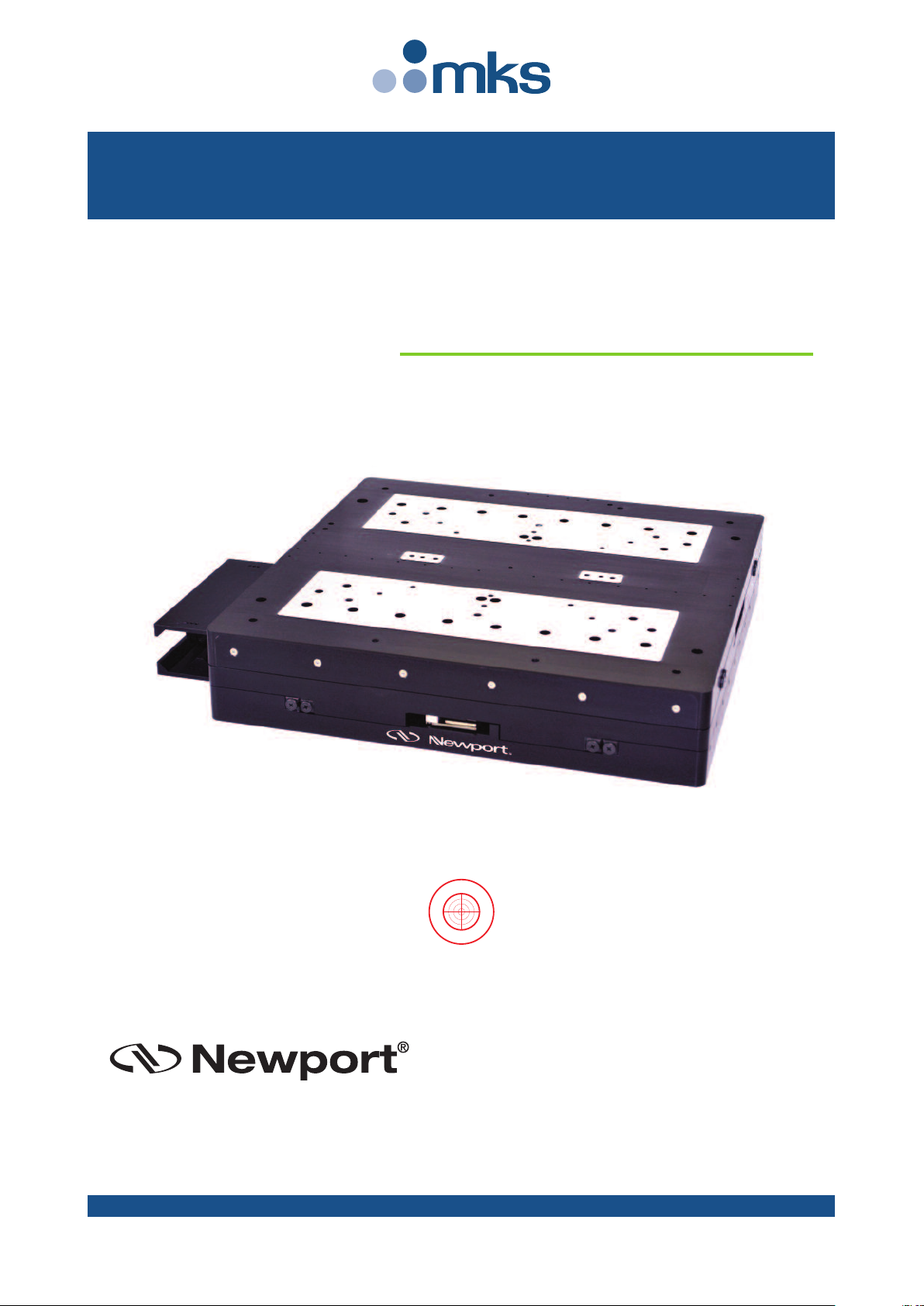
ONE-XY350 Stage.
RECOMMENDATION
We recommend you carefully read the chapter “Connection to
electronics” before using the ONE-XY stage.
1 EDH0351En1012 — 10/18
Page 12

ONE-XY Series Integrated XY Linear Motor Stages
2.0 —Description
The ONE-XY series of integrated XY linear motor stages are designed to
liminate the integration of individual X and Y stages and increase system
e
stiffness for dynamic applications. The available travel ranges from 60 mm
to 400 mm, with precise orthogonality alignment between the X and Y
axes.
The stages feature robust components and deliver high performance,
aking them ideal solutions for precision industrial applications such as
m
semiconductor wafer inspection, microelectronics test and assembly,
metrology, laser microprocessing.
The ONE-XY has a monolithic, aluminum middle plate that is stiffer than
the conventional interface between two individual linear stages. The linear
motor drive is an iron-less design that is suited for high precision
positioning, but at the same time offers high dynamic performance. Crossroller bearings provide high load capacity as well as straight trajectories.
Precision position feedback is supplied by a highly repeatable linear scale
mounted inside the stage. The encoder signals are interpolated by
Newport’s XPS motion controller with 50 nm MIM for outstanding
Minimum Incremental Motion, repeatability, and stability. Absolute home
position and limit signals are incorporated to improve repeatability and
reliability, while simplifying the design with less electronics and
mechanical parts.
2.1 Design Details
Base Material Aluminum
Bearings High precision crossed roller bearings
Drive System 3-phase synchronous ironless core linear motor
Motor Initialization Done by controller
Feedback Non-contact optical encoder
Limit & Home Switches Integrated home and end of travel limits
Cable High Flex, 10M cycle, 3 m length
MTBF 20,000 hours
EDH0351En1012 — 10/18 2
Page 13

ONE-XY Series Integrated XY Linear Motor Stages
Specifications of our products are established in reference to ISO 230
standard part II “Determination of accuracy and repeatability of
positioning numerically controlled axes”.
T
his standard gives the definition of position uncertainty which depends
on the 3 following parameters:
Absolute Accuracy
Difference between ideal position and real position.
Accuracy
Difference between ideal position and real position after the compensation
of linear errors.
Linear errors include: cosine errors, inaccuracy of screw or linear scale
pitch, angular deviation at the measuring point (Abbe error) and thermal
expansion effects. All Newport motion electronics can compensate for
linear errors.
The relation between absolute accuracy and on-axis accuracy is as follows:
Absolute Accuracy = Accuracy + Correction Factor
x Travel
Repeatability
Ability of a system to achieve a commanded position over many attempts.
Reversal Value (Hysteresis)
Difference between actual position values obtained for a given target
position when approached from opposite directions.
Minimum Incremental Motion (MIM or Sensitivity)
The smallest increment of motion a device is capable of delivering
consistently and reliably.
Resolution
The smallest increment that a motion device can theoretically move
and/or detect. Resolution is not achievable, whereas MIM, is the real
output of a motion system.
Yaw, Pi tch
Rotation of carriage around the Z axis (Yaw) or Y axis (Pitch), when it
moves.
The testing of accuracy, repeatability, and reversal error are made
systematically with test equipment in controlled environment (20±1°C).
A linear cycle with 21 data points on the travel and 4 cycles in each
direction gives a total of 168 points.
Guaranteed and Typical Specifications
Guaranteed maximum performance values are verified per Newport's A167
metrology test procedure. For more information, please consult the
metrology tutorial section in the Newport catalog or at www.newport.com
3.0 —Characteristics
3.1 Definitions
3 EDH0351En1012 — 10/18
Page 14

ONE-XY Series Integrated XY Linear Motor Stages
G
U
A
R
A
N
T
E
E
D
S
P
E
C
I
F
I
C
A
T
I
O
N
S
3.2 Mechanical Specifications
ONE-XY60 ONE-XY60HA ONE-XY100 ONE-XY100HA ONE-XY200 ONE-XY200HA ONE-XY300 ONE-XY300HA
Travel Range (mm) 50 x 50 90 x 90 190 x 190 290 x 290
inimum Incremental Motion (µm) 0.05 0.05 0.05 0.05 0.05 0.05 0.05 0.05
M
ccuracy, Typical (Guaranteed) (µm) ±0.4 (±1.5) n/a (±0.3) ±0.5 (±2.0) n/a (±0.3) n/a (±2.5) n/a (±0.4) n/a (±3.0) n/a (±0.5)
A
Bi-directional Repeatability,
ypical (Guaranteed) (µm)
T
5)
traightness, Typical
S
Flatness, Typical
itch, Typical (Guaranteed)
P
aw, Typical (Guaranteed)
Y
(3)
Roll
(µrad) 58 58 72 48
rthogonality
O
Max. Speed
Max. Acceleration
ax. Load Capacity (N) 100 120 150 350
M
(
µm) ±0.5 ±1.0 ±2.0 ±3.0
(
(2)
(µm) ±0.5 ±1.0 ±2.0 ±3.0
(3)(5)
µrad) ±20 (±65) n/a (±65) n/a (±75) n/a (±75) n/a (±90) n/a (±90) ±15 (±55) n/a (±55)
(
(3)(5)
µrad) ±20 (±65) n/a (±65) n/a (±75) n/a (±75) n/a (±90) n/a (±90) ±15 (±55) n/a (±55)
(
(3)
µrad) 96 96 96 96
(
(3)
(m/s) 0.3 0.4 0.5 0.3
(3)
(G) 0.3 0.3 0.2 0.2
Weight [lb (kg)] 6.4 (2.9) 12.8 (5.8) 26.4 (12) 165 (75)
1)
Specifications measured on stage centerline, 50 mm above mounting surface. Newport provides NIST traceable, test results.
2)
Flatness specifications dependent on system base. Contact Newport for more information.
3)
Stage performance values at no load. Does not account for drive or resolution effects.
4)
To obtain arcsec units, divide mrad value by 4.8.
5)
Over 80% of travel range.
Notes: HA versions are error mapped in XY.
Speed and acceleration can be higher with other driver options.
0.040 (±0.070) ±0.040 (±0.080) n/a (±0.090) n/a (±0.100)
±
The following specifications are controller/drive dependent. Refer to the
ONE-XY Series page on www.newport.com for specifications achievable
with specific Newport controller/drive combination.
• MIM
• Accuracy
• Repeatability
• Max Speed
• Max Acceleration
To reach stated specifications, the stages must be fixed on a plane
surface with a flatness of 5 µm.
3.3 Hard Stop
Hard stops are supplied, only for emergency use.
NOTE
CAUTION
3.4 Load Characteristics and Stiffness
Normal Load Capacity (Cz)
Maximum load a stage can move while maintaining specifications.
NOTE
For other than centered loads, please contact Newport technical
support.
EDH0351En1012 — 10/18 4
Page 15

ONE-XY Series Integrated XY Linear Motor Stages
U-V
-2
0
-0.5
-1
-1.5
0.5
1
1.5
2
Amplitude
U-WV-W
Induced Voltages Coil Moving
Motion Direction +
R
T
(Ω)
2500
2000
1500
1000
500
0
50
T
A
(°C)
100
EHA07248
-50 0 150
Positive Temperature Coefficient
Thermistor, resistance as a function
of temperature. Motor heating is
typically restricted to 20 °C with
Newport Controllers.
Direction +
Direction +
4.0 —Drive and Motor
4.1 Motor characteristics (Direct Drive Brushless Motor)
ONE-XY50 ONE-XY100 ONE-XY200 ONE-XY300 ONE-XY400
Magnet Pitch [N-N] (mm) 30.48 30.48 30.48 30.48 30.48
Max. Voltage [Line to Line]
(1)
(V) 500 500 500 500 500
Electrical Time Constant (ms) 0.19 0.19 0.20 0.20 0.20
Max. Motor Temperature (°C) 130 130 130 130 130
Motor Connection DELTA DELTA DELTA DELTA DELTA
Motor Constant (N2/W)
Force Constant (N/Apk) 8.1 16.3 28.7 43.0 57.4
Phase Resistance [@ 25 °C]
Phase Resistance [@ 130 °C]
(2)
(Ω) 5.8 11.6 11.7 17.6 23.5
2)
(
(Ω) 8.2 16.4 16.6 24.9 33.2
Thermal Resistance (°C/W)
Inductance (mH) 1.1 2.1 2.3 3.5 4.7
3)
Continuous Force
Continuous Current
Peak Force
Peak Current
Back EMF Constant (V/m/s) 8.1
1)
Back EMF plus IR drop must not exceed maximum line to line bus voltage.
)
2
Resistance values do not include cable resistance. Cable resistance adds 0.146 ohm/m for Delta connection and 0.44 ohm/m for Wye
Connection.
3)
Continuous operating limits are based on continuous operation at maximum temperature with aluminum heat sink (300mm x 12.5mm
x motor length).
4)
Maximum on time at peak operating limits is 10 seconds.
(
(N) 23 47 93 140 186
(3)
(4)
(Apk) 2.9 2.9 3.2 3.2 3.2
(N) 75 151 295 442 589
4)
(
(NApk) 9.2 9.2 10.3 10.3 10.3
16.3 28.7 43.0 57.4
CAUTION
High RMS current will generate motor heating which will degrade
characteristics of the stage, such as repeatability, accuracy, etc...
5 EDH0351En1012 — 10/18
4.2 Command Signals
NOTE
The values above indicate voltage induced by energized coil of one
phase on next phase coil. A positive value for U-V would indicate a
higher voltage on U relative to V.
4.3 Sensor Positions
Page 16

ONE-XY Series Integrated XY Linear Motor Stages
– End-of-Run Limit
+ End-of-Run Limit
Index Pulse
Index Pulse
Sensor Positions
Motion Direction +Direction –
1.97
(
50)
.08 (2).08 (2)
Negative
S
oftware Limit
Stage Travel Range
Positive
S
oftware Limit
Home Position
(
Origin)
D
imensions in inches
(
and millimeters)
Direction +
Direction +
Low
High
Low
High
Low
High
Low
H
igh
E
ncoder
P
hase A
Encoder
Phase A
Encoder
Phase B
Encoder
Phase B
1234
Encoder Feedback Signal Position
Motion Direction +Direction –
5
96
1
4.4 Position Feedback Signals
EDH0351En1012 — 10/18 6
Signal description / Voltage / wiring Renishaw standard 1 Vpp
Reference mark position see drawing "Sensor Positions"
Resolution Scale pitch 20 µm
Maximum speed 10 m/s
4.5 Pinouts
The pinout diagrams for the ONE-XY stage connectors are shown below.
4.5.1 Motor (SUB-D9M Connector)
1 U Motor
2 U Motor
3 V Motor
4 V Motor
5 Thermistor 1
6 W Motor
7 W Motor
8 Shield Ground
9 Thermistor 2
• Max. voltage: 96 V
• Max. rms Current: 3.1 A
Page 17

ONE-XY Series Integrated XY Linear Motor Stages
8
1
59
1
Motor Encoder &
End-of-Runs
SUB-D9M
Connector
1
2
3
4
6
7
8
Connector
Cap
ONE-XY
Stage
Phase U Motor
Phase U Motor
Phase V Motor
Phase V Motor
Phase W Motor
Phase W Motor
Ground
Connector
Cap
Sub-D15F
Connector
Encoder Phase A
Encoder Phase /A
Encoder Phase B
Encoder Phase /B
Index Pulse I
Index Pulse /I
+ End-of-Run
- End-of-Run
+5 V Encoder
+5 V
N.C.
N.C.
N.C.
Shield Ground
Connector
Cap
SUB-D15M
Connector
3
11
1
9
14
7
8
6
4
12
5
13
15
2-10
Connector
Cap
ARNING
W
GROUNDING: The stage's protective ground is located on pin #8 of the
motor power connector.
f you are using grounds other than those provided by Newport, you
I
must connect pin #8 to a ground connection.
4.5.2 Encoder and End-of-Runs (SUB-D15M Connector)
1 Encoder Phase B
2 Shield Ground
3 Encoder Phase A
4 +5 V Encoder
5 N.C.
6 – End-of-Run
7 Index Pulse /I
8 + End-of-Run
9 Encoder Phase /B
10 Shield Ground
11 Encoder Phase /A
12 +5 V
13 N.C.
14 Index Pulse I
15 N.C.
4.6 ONE-XY Cable Wiring
All ONE-XY stages are delivered with the three cables required for
operation. The wiring diagrams and connectors for these cables are
provided in the following diagrams. When operating the non-Newport
controllers, it is recommended to adhere to the wiring conventions
presented here and to use cabling with similar characteristics.
7 EDH0351En1012 — 10/18
This is the wiring of the cables that provided with the connection to
Newport Controllers, for third party controllers, we recommend using a
cable with similar characteristics.
NOTE
Page 18

ONE-XY Series Integrated XY Linear Motor Stages
5.0 —Stage Installation
5.1 Unpacking
The ONE-XY stage will be delivered to your site in packaging designed for
afe transport. Larger ONE-XY stages will be delivered in Pelican cases. All
s
accessories will be included in this case.
Attached to the body of the stage are handles for safe removal from
packaging. It is recommended to carefully lift the stage from packaging
using these handles.
CAUTION
The largest stages are quite heavy, and we recommd a two person job
or by some cherry picker.
CAUTION
Before operating the stage, remove the screws that hold the stages
during shipment.
EDH0351En1012 — 10/18 8
Page 19

ONE-XY Series Integrated XY Linear Motor Stages
OTE
N
Put away shipping screws, in case the unit needs to be returned to the
factory.
The stage will come delivered with a control report that indicates
performance of your stage within guaranteed specification. These
measurements were taken in a controlled environment under flat mounting
conditions.
5.2 Mounting Conditions
ONE-XY stages require the following mounting conditions for best
performance.
Installation Considerations
Mounting surface flatness 5 µm
Mounting screw torque 7 Nm
Mounting holes to a table, whether a granite or flat steel table can be
accessed by moving the stage manually
9 EDH0351En1012 — 10/18
Page 20

ONE-XY Series Integrated XY Linear Motor Stages
6.0 —Connection to Newport Controllers
OTE
N
Visit www.newport.com for compatible Newport controllers.
6.1 Warnings on Controllers
Controllers are intended for use by qualified personnel who recognize
shock hazards and are familiar with safety precautions required to avoid
possible injury. Read the controller user’s manual carefully before
operating the instrument and pay attention to all written warnings and
cautions.
Specifications listed in this guide are based on operation with Newport
Control and Drive Electronics. The XPS Controller is delivered with a
configuration file that has been developed at the factory for operation in a
no-load condition for immediate plug-and-play operation.
Newport has developed technical notes which guide the configuration
process for operation of ONE-XY stages with a non-zero, application
specific payload.
For operation under such conditions the Scaling Acceleration, Acceleration
Limit and PID tuning parameters may need to be adjusted. Please download
our tech notes on Scaling Acceleration, Tuning and configuring direct drive
stages on the ONE-XY page of the Newport website.
For additional information about controllers, visit www.newport.com.
WARNING
Disconnect the power plug under the following circumstances:
• If the power cord or any attached cables are frayed or damaged in
any way.
• If the power plug is damaged in any way.
• If the unit is exposed to rain, excessive moisture, or liquids are spilled
on the unit.
• If the unit has been dropped or the case is damaged.
• If you suspect service or repair is required.
• Whenever you clean the electronics unit.
To protect the unit from damage, be sure to:
• Keep all air vents free of dirt and dust.
• Keep all liquids away from the unit.
• Do not expose the unit to excessive moisture (85% humidity).
• Read this manual before using the unit for the first time.
All attachment plug receptacles in the vicinity of this unit are to be of
the grounding type and properly polarized.
Contact your electrician to check your receptacles.
EDH0351En1012 — 10/18 10
CAUTION
WARNING
Page 21

ONE-XY Series Integrated XY Linear Motor Stages
ARNING
W
This product operates with voltages that can be lethal.
Pushing objects of any kind into stage slots or holes, or spilling any
iquid on the product, may affect voltage points or short out parts. Any
l
unauthorized access to internal electronics represents a potential shock
hazard and precaution should be taken.
6.2 Connection
On each stage there is a label which indicates the stage name and serial
number.
WARNING
Always turn the controller's power OFF before connecting to a stage.
Stages may be connected to the rear panel motor connectors labeled
“Motor…” at any time prior to power-up with the supplied cable
assemblies.
6.3 Cables
All ONE-XY stages are delivered with a set of 3-meter cables with SUB-D
connectors for direct connection to Newport Controllers.
ONE-XY Series translation stages can only operate with cable lengths of
3 m or less.
These cables are shielded. For correct operation, make sure to lock
connectors (ground continuity provided by cables).
Keep the cables at a safe distance from other electrical cables in your
environment to avoid potential cross talk.
WARNING
WARNING
WARNING
11 EDH0351En1012 — 10/18
Page 22

ONE-XY Series Integrated XY Linear Motor Stages
7.0 —Connection to Non-Newport Controllers
Newport stages can be operated with Non-Newport controllers. However,
nder such operational conditions Newport makes no guarantee regarding
u
achievable specifications. To aid Newport customers using non-Newport
Controllers with ONE-XY stages we have provided wiring conventions and
motor characteristics below. It should be noted, damage caused by
improper configuration or operation while in use with non-Newport
ontrollers is not covered by the warranty.
c
Please refer to Design Details and Specifications for more information to
help configure the stage with your controller. Newport also provides a
tech note on configuring third party stages with Newport controllers on
ONE-XY website, which may be useful as a reference.
WARNING
Newport is not responsible for malfunction or damage of ONE-XY stages
when used with non-Newport controllers.
WARNING
Newport guarantees “”compliance of ONE-XY stages only if used
with the Newport cables and a XPS series controller.
It is the customer’s responsibility to modify the cable and take care of
sensor signal connections, when using the stage with non-Newport
controllers .
EDH0351En1012 — 10/18 12
Page 23

ONE-XY Series Integrated XY Linear Motor Stages
HEIGHT
H
G
G
E
F
EF
A
C
DB
WIDTH
W
G
LENGTH
L
CABLE OUTPUT
C
ABLE OUTPUT
S
TAGE MOUNT ON BOTH SIDES:
8
HOLES FOR "I" SCREWS
(
TOP DOWN ACCESS BY
T
RANSLATING STAGE)
3
HOLES ø.197
0
+
.012
(5
H
9
)
D
EPTH .20 (5)
S
LIP FIT FOR M5 DOWEL PIN
3
HOLES ø.197
0
+
.012
(5
H
9
)
D
EPTH .20 (5)
S
LIP FIT FOR M5 DOWEL PIN
BOTH SIDES:
HOLES "J" THD
B
OTH SIDES:
H
OLES "K" THD
M
STATIONARY
CABLE BRACKET
MOVING CABLE
BRACKET
M
ODEL B C D E F
O
NE-XY60
3.0 3.94 2.95 1.81 2.36
(76.2) (100) (75) (46) (60)
O
NE-XY100
4.0 4.92 3.94 1.81 4.72
(101.6) (125) (100) (46) (120)
O
NE-XY200
6.0 6.89 4.92 4.72 6.69
(152.4) (175) (125) (120) (170)
ONE-XY300
8.0 13.78 9.84 6.69 & 8.86 10.83
(203.2) (350) (250) (170 & 225) (275)
MODEL G I J K M
ONE-XY60
1.38 1/4-20 4 HOLES 4 HOLES
(35) or M6 M4 M5
–
ONE-XY100
2.76 1/4-20 4 HOLES 6 HOLES 2.05
(70) or M6 M4 M5 (52)
ONE-XY200
2.76 1/4-20 8 HOLES 6 HOLES 2.56
(70) or M6 M5 M6 (65)
ONE-XY300
3.94 5/16-18 8 HOLES 6 HOLES 3.78
(100) or M8 M6 M8 (96)
M
ODEL TRAVEL L W H A
O
NE-XY60
1.97 4.92 4.92 2.36 4.0
(50) (125) (125) (60) (101.6)
O
NE-XY100
3.54 7.24 7.24 2.36 6.0
(90) (184) (184) (60) (152.4)
O
NE-XY200
7.48 10.83 10.83 2.36 6.0
(190) (275) (275) (60) (152.4)
O
NE-XY300
11.42 19.69 19.69 3.94 12.0
(290) (500) (500) (100) (304.8)
MODEL SHOWN: ONE-XY100
DIMENSIONS IN INCHES (AND MILLIMETERS)
8.0 —Dimensions
13 EDH0351En1012 — 10/18
Page 24

ONE-XY Series Integrated XY Linear Motor Stages
9.0 —Maintenance
ECOMMENDATION
R
It is recommended to contact our After Sales Service which will know to
define the appropriate maintenance for your application.
9.1 Maintenance
The ONE-XY stage requires no particular maintenance. Nevertheless, this
is a precision mechanical device that must be kept and operated with
caution.
PRECAUTIONS
The ONE-XY stage must be used or stocked in a clean environment,
without dust, humidity, solvents or other substances.
It is recommended to return your ONE-XY stage to Newport's After Sales
Service after every 2000 hours of use for lubrication.
If your stage is mounted on a workstation and cannot be easily
removed, please contact Newport's After Sales Service for further
instructions.
9.2 Repair
Install the shipping screws to hold down the stage prior to packing.
Never attempt to disassemble a component of the stage that has not
been covered in this manual.
This can cause a malfunction of the stage.
If you observe a malfunction in your stage, please contact us immediately
to arrange for repair.
RECOMMENDATION
NOTE
CAUTION
Any attempt to disassemble or repair a stage without prior
authorization will void the warranty.
9.3 Calibration
It is recommended to return your ONE-XY stage to Newport once a year
for recalibration to its original specifications.
EDH0351En1012 — 10/18 14
CAUTION
CAUTION
Page 25

Your Lo ca l R ep re se nt at iv e
Tel. :
F
ax:
N
ame:
Company:
Address:
Country:
P. O . N u m b e r :
Item(s) Being Returned:
Model #:
Description:
Reasons of return of goods (please list any specific problems):
R
eturn authorization #:
(Please obtain prior to return of item)
Date:
Phone Number:
Fax Number:
Serial #:
Service Form
15 EDH0351En1012 — 10/18
Page 26

Visit Newport Online at:
North America & Asia
Newport Corporation
1791 Deere Ave.
Irvine, CA 92606, USA
Sales
Tel.: (800) 222-6440
e-mail: sales@newport.com
Technical Support
Tel.: (800) 222-6440
e-mail: tech@newport.com
Service, RMAs & Returns
Tel.: (800) 222-6440
e-mail: service@newport.com
Europe
MICRO-CONTROLE Spectra-Physics S.A.S
9, rue du Bois Sauvage
91055 Évry CEDEX
France
Sales & Technical Support
Tel.: +33 (0)1.60.91.68.68
e-mail: france@newport.com
Service & Returns
Tel.: +33 (0)2.38.40.51.55
www.newport.com
 Loading...