

Page 1
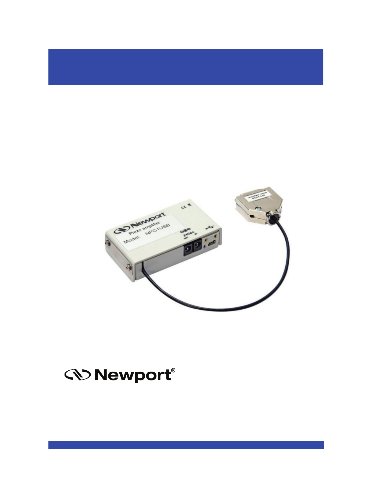
Voltage Piezo
USB Amplifier
User’s Manual
V1.0.x
NPC1USB
Page 2

NPC1USB Voltage Piezo USB Amplifier
Warranty
Newport Corporation warrants that this product will be free from defects in material and
workmanship and will comply with Newport’s published specifications at the time of
sale for a period of one year from date of shipment. If found to be defective during the
warranty period, the product will either be repaired or replaced at Newport's option.
To exercise this warranty, write or call your local Newport office or representative, or
contact Newport headquarters in Irvine, California. You will be given prompt assistance
and return instructions. Send the product, freight prepaid, to the indicated service
facility. Repairs will be made and the instrument returned freight prepaid. Repaired
products are warranted for the remainder of the original warranty period or 90 days,
whichever comes first.
Limitation of Warranty
The above warranties do not apply to products which have been repaired or modified
without Newport’s written approval, or products subjected to unusual physical, thermal
or electrical stress, improper installation, misuse, abuse, accident or negligence in use,
storage, transportation or handling. This warranty also does not apply to fuses, batteries,
or damage from battery leakage.
THIS WARRANTY IS IN LIEU OF ALL OTHER WARRANTIES, EXPRESSED OR
IMPLIED, INCLUDING ANY IMPLIED WARRANTY OF MERCHANTABILITY
OR FITNESS FOR A PARTICULAR USE. NEWPORT CORPORATION SHALL
NOT BE LIABLE FOR ANY INDIRECT, SPECIAL, OR CONSEQUENTIAL
DAMAGES RESULTING FROM THE PURCHASE OR USE OF ITS PRODUCTS.
©2017 by Newport Corporation, Irvine, CA. All rights reserved.
Original instructions.
No part of this document may be reproduced or copied without the prior written
approval of Newport Corporation. This document is provided for information only, and
product specifications are subject to change without notice. Any change will be
reflected in future publishings.
EDH0403En1010 — 07/17 ii
Page 3

NPC1USB Voltage Piezo USB Amplifier
Table of Contents
Waranty ............................................................................................................................ii
EU Declaration of Conformity ......................................................................................... v
1.0 Introduction .................................................................................................. 1
1.1 Scope of the Manual ........................................................................................................... 1
1.2 Certification of Newport Corporation ................................................................................ 1
1.3 Purchased Part Package ...................................................................................................... 2
1.4 Instructions for Using Piezo Electrical Elements and Power Supplies .............................. 2
1.5 Safety Instructions .............................................................................................................. 3
1.5.1 General Warning or Caution ................................................................................ 3
1.5.2 Electric Shock ...................................................................................................... 3
1.5.3 Icons ..................................................................................................................... 3
1.6 Warnings and Cautions ...................................................................................................... 4
2.0 Warnings and Cautions................................................................................ 5
2.1 Installation, Power Supply ................................................................................................. 6
2.2 Operation ............................................................................................................................ 6
2.3 Maintenance and Inspection ............................................................................................... 7
2.4 Environmental Conditions.................................................................................................. 7
3.0 NPC1USB Definition .................................................................................... 8
3.1 Keywords ........................................................................................................................... 8
3.2 User Elements/Connections ............................................................................................... 9
3.2.1 Front Pane ............................................................................................................ 9
3.3 Introduction ........................................................................................................................ 9
3.3.1 Block Diagram ..................................................................................................... 9
3.3.2 Amplifier without integrated feedback controller .............................................. 10
3.4 Initiation ........................................................................................................................... 10
3.4.1 Main Supply Voltage ......................................................................................... 10
3.4.2 Connecting Piezo Stage ..................................................................................... 10
4.0 Handling ...................................................................................................... 11
4.1 Controlling via Interface .................................................................................................. 11
4.2 Configuration USB 2.0 ..................................................................................................... 11
5.0 State Diagram ............................................................................................. 12
5.1 Command Syntax ............................................................................................................. 13
5.1.1 Blank Spaces ...................................................................................................... 13
iii EDH0403En1010 — 07/17
Page 4

NPC1USB Voltage Piezo USB Amplifier
5.1.2 Decimal Separator .............................................................................................. 13
5.1.3 Command Terminator ........................................................................................ 13
5.1.4 Command Execution Time ................................................................................ 13
5.1.5 Command Set ..................................................................................................... 14
6.0 Command Overview ................................................................................... 15
ID — Set/Get Stage Identifier ........................................................................................ 16
MM – Enter/Leave DISABLE State ............................................................................... 17
OR — Enable Output Stage and Set Initial Voltage ....................................................... 18
PA — Move Absolute .................................................................................................... 19
PR — Move Relative ...................................................................................................... 20
PW — Enter/Leave CONFIGURATION State .............................................................. 21
RS — Reset Controller ................................................................................................... 22
RS## — Reset Controller’s Address to 1 ....................................................................... 23
SA — Set/Get Controller’s RS-485 Address .................................................................. 24
SE — Do Nothing, No Error for Compatibility .............................................................. 25
SL — Set/Get Negative Software Limit ......................................................................... 26
SR — Set/Get Positive Software Limit .......................................................................... 27
ST — Stop Motion ......................................................................................................... 28
TB — Get Command Error String .................................................................................. 29
TE — Get Last Command Error ..................................................................................... 30
TH — Set/ Get Point Position ........................................................................................ 31
TP — Same as TH for Compatibility ............................................................................. 32
TS — Get Positioner Error and Controller State ............................................................ 33
VA — Set/Get Slow Rate ............................................................................................... 35
VE — Get Controller Revision Information ................................................................... 36
ZT — Get All Axis Parameters ...................................................................................... 37
7.0 Pinouts ......................................................................................................... 38
7.1 24 VDC IN and OUT (Female ø 2.1 x Ø 5.5 x 11 mm) ................................................... 38
7.2 USB Connector (USB Mini-B Receptacle) ...................................................................... 38
8.0 Electrical Specifications ............................................................................. 39
9.0 Mechanical Specifications .......................................................................... 39
10.0 Environmental Conditions ....................................................................... 39
Service Form ........................................................................................................ 41
EDH0403En1010 — 07/17 iv
Page 5

NPC1USB Voltage Piezo USB Amplifier
EU Declaration of Conformity
EDH0403En1010 — 07/17 v
Page 6

NPC1USB Voltage Piezo USB Amplifier
EDH0403En1010 — 07/17 vi
Page 7
NPC1USB Voltage Piezo USB Amplifier
User’s Manual
CAUTION
Please read carefully before switching on the power. Please see also
instructions for safety when using piezoelectric actuators and power
supplies
.
1.0 Introduction
1.1 Scope of the Manual
This manual describes the piezo amplifier NPC1USB from Newport Corporation.
If you have any problems please contact the manufacturer of the system:Newport
Corporation, 1791 Irvine Ave. Irvine, CA 92606. Phone: (877) 835-9620
1.2 Certification of Newport Corporation
Newport Corporation works in according to an ISO 9001:2008 certified quality
management system. Its effectiveness is verified and proven by periodic audits by the
BSI. Our certificate can be found at newport.com
CAUTION
This instruction manual includes important information for using
piezo actuators. Please take time and read this information. Piezo
positioning systems are mechanical systems with highest precision.
Correct handling
guarantees the precision over long time.
1 EDH0403En1010 — 07/17
Page 8

NPC1USB Voltage Piezo USB Amplifier
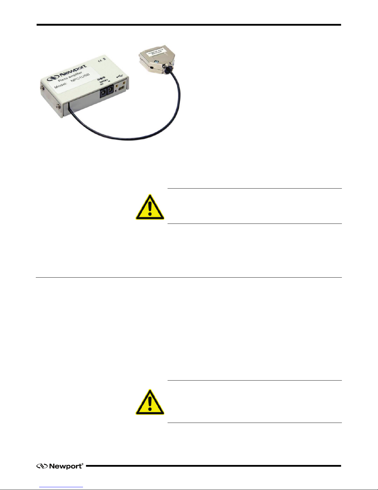
1.3 Purchased Part Package
Please check the completeness of the delivery after receiving the shipment:
• Voltage amplifier NPC1USB
• Power supply 24 VDC (Sold Separately – Model: CONEX-PS recommended)
• USB cable
• Quick Start Guide (available on Newport.com)
• .INF Drivers (available on Newport.com)
1.4 Instructions for Using Piezo Electrical Elements and Power Supplies
• Piezoelectric actuators from Newport Corporation are controlled by voltages up to
150V. These values can be quite hazardously. Therefore, please read the installation
instructions carefully.Only authorized personal should handle the power supply.
• After transportation, piezoelectric actuators should be allowed to sit for
approximately 2 hours to adapt to room temperature before being switched on.
• Piezoelectric actuators are made from ceramic materials with and without metallic
casings. The piezo-ceramic is a relatively brittle material. This should be noted when
handling piezo electric actuators. All piezo-elements are sensitive to bending or
shock forces.
• Due to the piezoelectric effect, piezo-actuators can generate electrical charges by
changing the mechanical load or the temperature or by such actions described above.
• Piezoelectric actuators are able to work under high compressive forces. Only
actuators with a pre-load can be used under tensile loads (these tensile forces must
be less than the pre-load, given in the data sheet).
• Please note that the acceleration of the ceramic material (e.g., caused by a fall,
discharging, or high dynamic applications) will occur.After excitation of the
actuators by a voltage in the upper control range, the ceramic will move and
generate an opposite high voltage after disconnection.
• Heating of the ceramic material will occur during dynamic operation and is caused
by structure conditional loss processes. Failure may occur if the temperature exceeds
specified values cited below.
• The piezoelectric effect disappears with increasing temperature up to the Curie
temperature (usual values approx. 140–250 °C).
• Piezoelectric actuators such as stacks or other devices work electrically as a
capacitor. These elements are able to store electrical energy over a long period of
time (up to some days) and the stored energy may be dangerous.
• If the actuator remains connected to the drive electronics, it will be unloaded within
a second after shutdown and quickly reaches harmless voltage values.
• Piezo-actuators can generate voltages by warming or cooling only (a result of
longitudinal change). The discharge potential should not be ignored due to the inner
capacitance. This effect is insignificantly at room temperature.
• Piezo-actuators from Newport Corporation are adjusted and glued. Any opening of
the unit will cause misalignment or possible malfunction and the guarantee will be
voided.
• Please use only original parts from Newport Corporation.
• Please contact Newport Corporation or your local representative, if there are any
problems with your actuator or power supply.
EDH0403En1010 — 07/17 2
Page 9
NPC1USB Voltage Piezo USB Amplifier
CAUTION
Shock forces may damage the built-in ceramic elements. Please avoid
such forces, and handle the units with care, otherwise the guarantee
is voided.
1.5 Safety Instructions
1.5.1 General Warning or Caution
Figure 1: General Warning or Caution Symbol.
The Exclamation Symbol in Figure 1 may appear in Warning and Caution tables in this
document. This symbol designates an area where personal injury or damage to the
equipment is possible.
1.5.2 Electric Shock
Figure 2: Electrical Shock Symbol.
The Electrical Shock Symbol in Figure 2 may appear on labels affixed to the DL
Controller/Driver. This symbol indicates a hazard arising from dangerous voltage. Any
mishandling could result in irreparable damage to the equipment, in personal injury, or
death.
1.5.3 Icons
European Union CE Mark
CE Mark.
The presence of the CE Mark on New Focus equipment means that this instrument has
been designed, tested and certified compliant to all applicable European Union (CE)
regulations and recommendations.
Waste Electrical and Electronic Equipment (WEEE)
WEEE Directive Symbol.
3 EDH0403En1010 — 07/17
Page 10

NPC1USB Voltage Piezo USB Amplifier
This symbol on the product or on its packaging indicates that this product must not be
disposed with regular waste. Instead, it is the user responsibility to dispose of waste
equipment according to the local laws. The separate collection and recycling of the
waste equipment at the time of disposal will help to conserve natural resources and
ensure that it is recycled in a manner that protects human health and the environment.
For information about where the user can drop off the waste equipment for recycling,
please contact your local Newport representative.
Control of Hazardous Substances
RoHS Compliant Symbol
This label indicates the products comply with the EU Directive 2011/65/EC that
restricts the content of six hazardous chemicals.
1.6 Warnings and Cautions
The following are definitions of the Warnings, Cautions and Notes that may be used in
this manual to call attention to important information regarding personal safety, safety
and preservation of the equipment, or important tips.
WARNING
Situation has the potential to cause bodily harm or death.
CAUTION
Situation has the potential to cause damage to property or
equipment.
NOTE
Additional information the user or operator should consider.
EDH0403En1010 — 07/17 4
Page 11
NPC1USB Voltage Piezo USB Amplifier
2.0 Warnings and Cautions
RISK OF ELECTRIC SHOCK
• Do not open the units! There are no user serviceable parts
insideOpening or removing covers may expose you to dangerous
shock hazards and other risks. Refer all servicing to qualified
service personnel.
• Do not spill any liquids into the cabinet or use the units near
water
.
CAUTION
• Allow adequate ventilation around the units so that heat can
properly dissipate. Do not block ventilated openings or place the
units near a radiator, oven, or other heat sources. Do not put
anything on top of the units except those that are designed for this
purpose (e.g. actuators).
• Work with the units only in a clean and dry environment. Only
specially prepared units (e.g. actuators) can work under other
conditions.
• Please only use original parts from Newport Corporation.
• Newport Corporation does not provide any warranty for damages
or malfunctions caused by additional parts not supplied by
Newport Corporation. Additional cables or connectors will change
the calibration and other specified data. This can change the
specified properties of the units and cause them to malfunction.
• Do not place the units on a sloping or unstable cart, stand, or table
as they may fall or not work accurately.
• Piezo elements are sensitive systems capable of the highest
positioning accuracy. However, they only demonstrate their
excellent properties if they are handled correctly. Please only
mount them at the special mounting points.
Immediately unplug your unit from the wall outlet and refer
servicing to qualified service personnel under the following
conditions:
• When the power supply cord or plug is damaged.
• If cleaning supplies or liquid has been spilled or objects have
fallen into the unit.
• If the unit has been exposed to rain or water.
• If the unit has been dropped or the housing is damaged.
5 EDH0403En1010 — 07/17
Page 12
NPC1USB Voltage Piezo USB Amplifier
2.1 Installation, Power Supply
RISK OF ELECTRIC SHOCK
• Do not insert or unplug the power plug with wet hands, as this
may result in electrical shock.
• Do not install in rooms where flammable substances are stored. If
flammable substances come into contact with electrical parts
inside, a fire or electrical shock may occur.
• Do not damage or modify the power cord. Do not pull on,
excessively bend, or place heavy objects on the power cord, as this
could cause electrical damage and result in a fire or electrical
shock.
• Always grasp the plug portion when unplugging the power plug.
Pulling on the cord may expose or snap the core wire, or
otherwise damage the power cord. Damaging the cord may cause
an electricity leak and result in a fire or electrical shock.
CAUTION
• Do not use accessories other than those provided (e.g. power
cord). Plug the power cord only in grounding equipment
conductor power sockets to prevent inadvertent loosening.
• Do not place heavy objects on any cables (e.g. power cords, sensor
cables, actuator cables, optical cables).
• Leave sufficient space around the power plug so that it can be
unplugged easily. If objects are placed around the power plug, you
will be unable to unplug it in case of an emergency.
• Install the system so that the on/off-switch is accessible without
problem.
2.2 Operation
Please note the area with general safety precautions.
RISK OF ELECTRIC SHOCK
Do not spill inflammable substances inside the voltage amplifier. If
these substances come into contact with an electrical component
inside the voltage amplifier, a fire or electrical shock may occur.
CAUTION
If the voltage amplifier emits smoke, excess heat, or unusual smells,
immediately turn off the power switch and unplug the power plug
from the outlet. Then contact Newport Corporation for technical
services.
EDH0403En1010 — 07/17 6
Page 13

NPC1USB Voltage Piezo USB Amplifier
2.3 Maintenance and Inspection
CAUTION!
• When cleaning the exterior box of the voltage amplifier, first turn
off the power switch and unplug the power plug. Failure to follow
these procedures may result in a fire or electrical shock.
• Clean the exterior box using a firmly wrung-out cloth. Do not use
alcohols, benzene, paint thinner or other inflammable substances.
If flammable substances come into contact with an electrical
component inside the voltage amplifier, a fire or electrical shock
may occur.
2.4 Environmental Conditions
The amplifier can be used in the following environmental conditions:
• Indoor
• Altitude up to 2,000 m
• Temperature: -40–80 °C
• Relative humidity: 5–80% (non-condensing)
The recommended environmental conditions detailed in the following:
• Indoor
• Altitude up to 2,000 m
• Temperature: 15–40 °C
• Relative humidity: 10– 70% (non-condensing)
7 EDH0403En1010 — 07/17
Page 14

NPC1USB Voltage Piezo USB Amplifier
3.0 NPC1USB Definition
Piezo Amplifier for one PZT Actuator with a USB Interface; no feedback sensor (i.e.
Open Loop Mode).
3.1 Keywords
Closed Loop
The operating mode for piezo actuating systems with integrated feedback sensor
system; position accuracy is constantly controlled.
Open Loop
The operating mode for actuating systems without feedback sensor inside;no position
information is available.
Modulation Input
The amplifier can be controlled by an applied analogue voltage signal from 0 V to
+10 V.
Monitor Output
The output voltage signal corresponds to the position of the piezo actuating system with
the applied voltage signal (OPEN LOOP mode only for NPC1USB).
PC Interface
USB 2.0
Hyper Terminal Program
This software enables the control of the piezo actuating system by using the USB
interface. The available commands are described in chapter 5.0: “State Diagram”.
Soft Start
Initialize after turning-on procedure. During the initialization sequence, the piezo
electrical actuator is controlled for approximately 10 seconds with a voltage signal of
130 V.
NOTE
The actuating system is moving during the initialization process.
Main Supply Voltage
The main supply voltage to the amplifier is 24 VDC; an external wide range power
supply needed for use (Recommended: CONEX-PS from Newport Corporation).
EDH0403En1010 — 07/17 8
Page 15
NPC1USB Voltage Piezo USB Amplifier
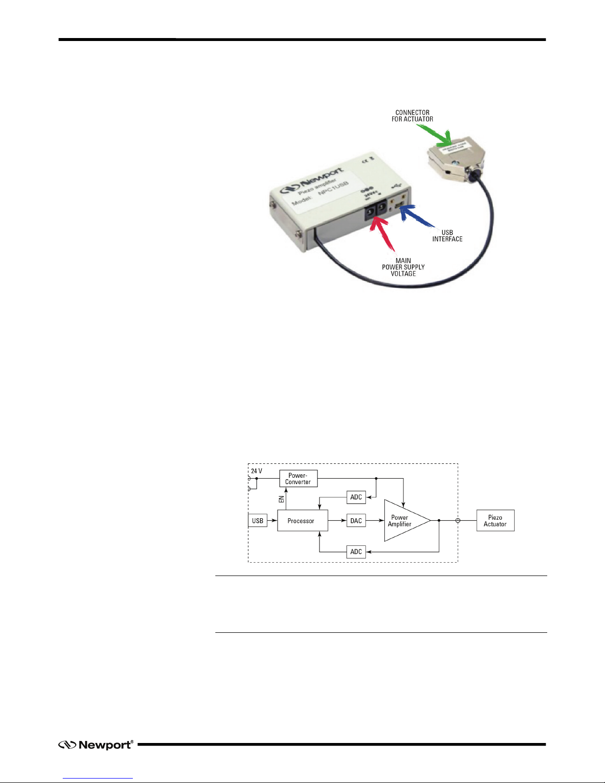
3.2 User Elements/Connections
3.2.1 Front Panel
3.3 Introduction
The NPC1USB piezo stack amplifier is designed to control one low voltage piezo
actuator with higher output current. The amplifier comes as a stand-alone device with a
standard PC interface and USB connection. The NPC1USB can be controlled by an
analog voltage signal of 24 V or by PC interface.
The NPC1USB is designed to control open loop actuating systems without any internal
feedback sensor.
3.3.1 Block Diagram
The chart below shows the block diagram of the NPC1USB. With exception of the
display and the processor, the circuit is a similar of the NPC amplifier series.
NOTE
The travel capability of actuators or stages is limited to 80% due to the limited
voltage range of the NPC1USB. With a lower current, the achievable rise times
and frequencies are expected to be lower depending on the actuator/stage type.
9 EDH0403En1010 — 07/17
Page 16

NPC1USB Voltage Piezo USB Amplifier
3.3.2 Amplifier without integrated feedback controller
Any system delivered in open loop mode cannot be modified to be in closed loop later
on.
Any closed loop system can be easily calibrated to a different closed loop piezo. This is
only possible at Newport Corporation and will require additional effort and costs.
Please contact our sales team for more information.
3.4 Initiation
Please follow all safety instructions given in this user manual and the NPC1USB Quick
Start Guide.
3.4.1 Main Supply Voltage
The NPC1USB amplifier requires a main supply voltage of 24 VDC. A power supply
unit suitable for voltages from 100 up to 240 Volt AC is included in the shipment. The
socket for the main supply voltage is located on the back panel of the amplifier.
3.4.2 Connecting Piezo Stage
Piezo electric stages are connected to the amplifier unit by using the D-SUB connector
on the back panel. Please make sure that the amplifier is switched off when connecting /
disconnecting the PZT to the amplifier. Please fasten the screws of the D-SUB
connector to guarantee a firm connection.
Please refer to the instructions and list of commands in Chapter 10 of this manual.
EDH0403En1010 — 07/17 10
Page 17

NPC1USB Voltage Piezo USB Amplifier
4.0 Handling
4.1 Controlling via Interface
The amplifier NPC1USB is controlled via an USB 2.0 interface. Therefore, signal
parameters and information about the actuator position or status can be adjusted or
settled directly in the computer interface. Furthermore, the system settings of the
amplifier unit can also be changed by using the interface. A fully PC controlled piezo
system for automation purposes is feasible. Please connect the amplifier system by
using the USB interface with your PC.
Please Note: The Piezo Amplifier must be turned off during this process.
For using the interface, a simple Terminal-Program can be used. (Please note that the
program “WINDOWS-HyperTerminal” isn’t a part of Microsoft® WINDOWS since
WINDOWS–VISTA is launched). By using the USB interface, please install the
necessary driver which is supplied on the Newport Corporation website at:
www.newport.com/p/NPC1USB
The supplied VI-driver is used for the integration of the amplifier systems into an
existing Lab-View® program or for programming of a new program. As a part of the
supplied software package software for controlling of the amplifier units is included or
can be downloaded from our web site as well.
4.2 Configuration USB 2.0
For external control by PC interface USB 2.0 the following settings are necessary:
Baud rate / Bits per second
57,600
Data bits
8
Stop bits
1
Parity
None
Flow control
Hardware
11 EDH0403En1010 — 07/17
Page 18

NPC1USB Voltage Piezo USB Amplifier
5.0 State Diagram
For a safe and consistent operation, the NPC1USB Uses 6 different operation states:
Not referenced, Configuration, Homing, Ready, Disable and Moving. In each state, only
specific commands are accepted by the NPC1USB. It is important to understand the
state diagram below and which commands and actions cause transition between
different states. Also, see the TS command for command/state information:
End of Runs encountered in the following state
NOT REFERENCED: No action
CONFIGURATION: No action
HOMING: Set voltage to zero and then change to NOT
REFRENCED state
MOVING: Abort motion and then change to NOT REFRENCED
state
READY: Change to NOT REFERENCED state
DISABLE: Change to NOT REFERENCED state
LED display
NOT REFERENCED: If everything is OK then SOLID ORANGE
NOT REFERENCED: If hardware faults or wrong parameters the SOLID RED
NOT REFERENCED: If end of runs then SLOW BLINK ORANGE
CONFIGURATION: SLOW BLINK RED
READY: SOLID GREEN
DISABLE: SLOW BLINK GREEN
HOMING: FAST BLINK GREEN
MOVING: FAST BLINK GREEN
After connecting the NPC1USB to power, the controller must first be initialized. When
the initialization is successful, the controller gets to the NOT REFRENCED state. From
the NOT REFRENCED state, the controller can go to the CONFIGURATION state
Configuration
Not Referenced
Moving
Disable
Homing
Ready
RS
PW1
PW0
OR
Following Error
Done
PA/PR
Done
MM0
MM1
Hardware Fault
• no power supply voltage
• no high voltage for the actuator
• actuator voltage is lower than expected
EDH0403En1010 — 07/17 12
Page 19

NPC1USB Voltage Piezo USB Amplifier
with the PW1 command. In CONFIGURATION state, the NPC1USB allows changing
all stage configuration parameters like? The PW0 command saves all changes to the
controller’s memory and returns the controller back to the NOT REFERENCED state.
To execute any move commands (PA, PR), the controller must be in the READY state.
To get from the NOT REFERENCED state to the READY state, the positioned must be
homed first with the OR command. During homing (OR command execution), the
controller is in HOMING state. If the homing is successful, the controller automatically
gets to the READY state. The process for homing, and which signals are looked for
during homing, can be defined with the HT command.
5.1 Command Syntax
The NPC1USB is a command driven controller. The general format of a command is a
two letter ASCII character preceded and followed by parameters specific to the
command:
Command format:
nn
AA
xx
nn Optional or required controller address.
AA Command name.
xx Optional or required value or “?” to query current value.
Both, upper and lower case characters are accepted. Depending on the command, it can
have an optional or required prefix (nn) for the controller address and/or a suffix (xx)
value or a “?”.
5.1.1 Blank Spaces
Blanks are allowed and ignored in any position, including within a numerical value. The
following two commands are equivalent, but the first example might be confusing and
uses more memory:
2PA1.43 6
2PA1.436
5.1.2 Decimal Separator
A dot (“.”) is used as a decimal separator for all numerical values.
5.1.3 Command Terminator
Commands are executed as the command terminator CRLF (carriage-return line-feed,
ASCII 13 and ASCII 10) is received. The controller will analyze the received string. If
the command is valid and its parameters are in the specified range, it will be executed.
Otherwise it will be memorized as an error.
After the execution of the command, all remaining characters in the input string, if any,
will be ignored. Therefore, it is not possible to concatenate several commands on a
single string from the PC to the NPC1USB.
Each command will properly handlethe memorization of related errors that can be
accessed with the TE command. Please refer to the command set in chapter 5.1.5 for
details.
5.1.4 Command Execution Time
The NPC1USB controller interprets commands continuously as they are received. The
typical execution time for a "tell position command" (nTP?) is about 10 ms. Here,
13 EDH0403En1010 — 07/17
Page 20

NPC1USB Voltage Piezo USB Amplifier
command execution time means the time from sending the command until receiving the
answer.
It is important to note that a move command that may last for several seconds, will not
suspend the controller from further command execution. So for an efficient process flow
with many move commands, it is recommended to use the PT command (to get time for
a relative move), the TS command (to query the controller status) , or the TP command
(to get current position) before any further motion command is sent.
5.1.5 Command Set
This chapter describes the supported two-letter ASCII commands used to configure and
operate the NPC1USB. The general command format is:
nn
AA
xx
nn Optional or required controller address.
AA Command name.
xx Optional or required value or “?” to query current value.
Most commands can be used to set a value (in that case the command name is followed
by the value “xx”) or to query the current value (in that case the command name is
followed by a “?”). When querying a value, the controller responds with the command it
received followed by the queried value. For example, a 1VA10 sets the velocity of the
controller #1 to 10 units/second. A “1VA?” sends the response “1VA10”.
Not every command can be executed in all states of the NPC1USB and some commands
have different meaning in different states. It is therefore important to understand the
state diagram of the controller, see chapter 5.0: “State Diagram”.
EDH0403En1010 — 07/17 14
Page 21

NPC1USB Voltage Piezo USB Amplifier
6.0 Command Overview
Not Ref. Config. Disable Ready Motion Description
ID – - Set/Get stage identifier
MM – –
– Enter/Leave DISABLE state
OR – – – – Enable output stage and set initial voltage
PA – – – – Move absolute
PR – – –
– Move relative
PW – – – Enter/Leave CONFIGURATION state
RS – – Reset controller
RS## Reset controller’s address to 1
SA – – – – Set/Get controller’s RS-485 address
SE – – – –
Do nothing, no error for compatibility
SL –
– Set/Get negative software limit
SR – – Set/Get positive software limit
ST - – – – Stop motion instead
TB Get command error string
TE Get last command error
TH Get setpoint position
TP Same as TH for compatibility
TS Get positioner error and controller state
VA – – Set/Get slew rate
VE Get controller revision information
ZT Get all axis parameters
Motion: Corresponds to HOMING and MOVING state (for details see chapter 5.0:
“State Diagram”).
Changes configuration parameters. Those changes will be stored in the
controller’s memory with the PW1 command and remain available after
switching off the controller.
Changes working parameters only. Those changes will get lost when
switching off the controller.
Accepted command.
– Not accepted command (will return an error).
Command: Command passed without preceding controller number applies to all
controllers (e.g. MM0 disables all controllers).
15 EDH0403En1010 — 07/17
Page 22

NPC1USB Voltage Piezo USB Amplifier
ID — Set/Get Stage Identifier
Usage Not Ref. Config. Disable Ready Motion
–
–
Syntax xxIDnn, or xxID?
Parameters
Description xx [int] — Controller address.
nn [float] — Stage model number.
Range xx — 1 to 31.
nn — 1 to 31 ASCII characters.
Units xx — None.
nn — None.
Defaults xx Missing: Error B.
Out of range: Error B.
Floating point: Error A.
nn Missing: Error C.
Out of range: Error C.
Description This ID? command gets the stage identifier. In CONFIGURATION mode, this
Command allows changing the stage identifier.
Returns If the sign “?” takes place of nn, the command returns the current programmed value.
Errors A — Unknown message code or floating point controller address.
B — Controller address not correct.
C — Parameter missing or out of range.
D — Execution not allowed.
H — Execution not allowed in NOT REFERENCED state.
L — Execution not allowed in HOMING state.
M — Execution not allowed in MOVING state.
Rel. Commands None.
Example 1ID? | Get stage identifier for controller #1.
1IDNPC1USB | Controller returns stage identifier: NPC1USB.
EDH0403En1010 — 07/17 16
Page 23

NPC1USB Voltage Piezo USB Amplifier
MM – Enter/Leave DISABLE State
Usage Not Ref. Config. Disable Ready Motion
– – –
Syntax xxMMnn or xxMM?
Parameters
Description xx [int] — Controller address.
nn [float] — ?
Range xx — 1 to 31.
nn — 0 changes state from READY to DISABLE.
1 changes state from DISABLE to READY.
Units xx — None.
nn — None.
Defaults xx Missing: Error B.
Out of range: Error B.
Floating point: Error A.
nn Missing: Error C.
Out of range: Error C.
Description MM0 changes the controller’s state from READY to DISABLE. In the DISABLE state
the actuator is not energized.
MM1 changes the controller’s state from DISABLE to READY. The controller’s set
point is equal to its current position.
Returns If the sign “?” takes place of nn, the command returns the current programmed value.
Errors A — Unknown message code or floating point controller address.
B — Controller address not correct.
C — Parameter missing or out of range.
D — Execution not allowed.
H — Execution not allowed in NOT REFERENCED state.
I — Command not allowed in CONFIGURATION state.
L — Execution not allowed in HOMING state.
M — Execution not allowed in MOVING state.
Rel. Commands PW — Enter/leave CONFIGURATION state.
Example MM0 | All controllers go to DISABLE state.
17 EDH0403En1010 — 07/17
Page 24

NPC1USB Voltage Piezo USB Amplifier
OR — Enable Output Stage and Set Initial Voltage
Usage Not Ref. Config. Disable Ready Motion
– – – –
Syntax xxOR
Parameters
Description xx [int] — Controller address.
Range xx — 1 to 31.
Units xx — None.
Defaults xx Missing: Error B.
Out of range: Error B.
Floating point: Error A.
Description This command enables the output stage and sets the voltage to SL.
Returns If the sign “?” takes place of nn, the command returns the current programmed value.
Errors A — Unknown message code or floating point controller address.
B — Controller address not correct.
D — Execution not allowed.
I — Command not allowed in CONFIGURATION state.
J — Execution not allowed in DISABLE state.
K — Execution not allowed in READY state.
L — Execution not allowed in HOMING state.
M — Execution not allowed in MOVING state.
Rel. Commands PW – Enter/leave CONFIGURATION state.
Example 1OR | Enables output stage of the controller #1 and sets the voltage to 0 V.
EDH0403En1010 — 07/17 18
Page 25

NPC1USB Voltage Piezo USB Amplifier
PA — Move Absolute
Usage Not Ref. Config. Disable Ready Motion
– – – –
Syntax xxPAnn or xxPA?
Parameters
Description xx [int] — Controller address.
nn [float] — Actuator voltage.
Range xx — 1 to 31.
nn — SL ≤ nn ≤ SR.
Units xx — None.
nn — Voltage.
Defaults xx Missing: Error B.
Out of range: Error B.
Floating point: Error A.
nn Missing: Error C.
Out of range: Error C.
Description The PA command initiates an absolute move. When received, the actuator will move,
with the predefined slew rate, to the new target position specified by nn.
The PA command is only accepted in the READY state, AND when the new target
position is higher or equal to the negative software limit (SL), AND lower or equal to
the positive software limit (SR).
Returns If the sign “?” takes place of nn, the command returns the current programmed value.
Errors A — Unknown message code or floating point controller address.
B — Controller address not correct.
C — Parameter missing or out of range.
D — Execution not allowed.
H — Execution not allowed in NOT REFERENCED state.
I — Command not allowed in CONFIGURATION state.
J — Execution not allowed in DISABLE state.
L — Execution not allowed in HOMING state.
M — Execution not allowed in MOVING state.
Rel. Commands PR — Move relative.
TH — Get set-point voltage.
TP — Get current position (Please notice: same as TH).
Example 1PA45.00 | Move actuator on controller #1 to the absolute position 45.00 V.
19 EDH0403En1010 — 07/17
Page 26

NPC1USB Voltage Piezo USB Amplifier
PR — Move Relative
Usage Not Ref. Config. Disable Ready Motion
– – – –
Syntax xxPRnn or xxPR?
Parameters
Description xx [int] — Controller address.
nn [float] — ?
Range xx — 1 to 31.
nn — SL ≤ (abspos + nn) ≤ SR.
Units xx — None.
nn — Voltage.
Defaults xx Missing: Error B.
Out of range: Error B.
Floating point: Error A.
nn Missing: Error C.
Out of range: Error C.
Description The PR command initiates a relative move. When received, the actuator will move, with
the predefined slew rate, to the new target position nn units away from the current
position.
The PR command is only accepted in the READY state, AND when the distance of the
position to the end of runs is larger than the commanded displacement.
Returns If the sign “?” takes place of nn, the command returns the current programmed value.
Errors A — Unknown message code or floating point controller address.
B — Controller address not correct.
C — Parameter missing or out of range.
D — Execution not allowed.
H — Execution not allowed in NOT REFERENCED state.
I — Command not allowed in CONFIGURATION state.
J — Execution not allowed in DISABLE state.
L — Execution not allowed in HOMING state.
M — Execution not allowed in MOVING state.
Rel. Commands PW – Enter/Leave CONFIGURATION state.
Example 1PR2.2 | Move positioned on controller #1 to a new position 2.2 units away
from the current target position.
EDH0403En1010 — 07/17 20
Page 27

NPC1USB Voltage Piezo USB Amplifier
PW — Enter/Leave CONFIGURATION State
Usage Not Ref. Config. Disable Ready Motion
– – –
Syntax xxPWnn or xxPW?
Parameters
Description xx [int] — Controller address.
nn [float] — ?
Range xx — 1 to 31.
nn — 1: changes from NOT REFERENCED state to CONFIGURATION
state.
0: changes from CONFIGURATION state to NOT REFERENCED
state.
Units xx — None.
nn — None.
Defaults xx Missing: Error B.
Out of range: Error B.
Floating point: Error A.
nn Missing: Error C.
Out of range: Error C.
Description PW1 changes the controller’s state from NOT REFERENCED to CONFIGURATION.
In the CONFIGURATION state all parameter settings are saved in the controller’s
memory and will remain available even after switching off the controller. Additionally,
some settings are only possible in the CONFIGURATION state.
Saved parameters are SA, SL, SR, ID, VA.
PW0 checks all the stage parameters and saves them in the flash memory of the
controller if they are acceptable. After that, it changes the controller’s state from
CONFIGURATION to NOT REFERENCED.
Returns If the sign “?” takes place of nn, thes command returns the current programmed value.
Errors A — Unknown message code or floating point controller address.
B — Controller address not correct.
C — Parameter missing or out of range.
D — Execution not allowed.
J — Execution not allowed in DISABLE state.
K — Execution not allowed in READY state.
L — Execution not allowed in HOMING state.
M — Execution not allowed in MOVING state.
Rel. Commands MM — Enter/Leave DISABLE state.
Example 1PW1 | Changes controller #1 to CONFIGURATION state.
21 EDH0403En1010 — 07/17
Page 28

NPC1USB Voltage Piezo USB Amplifier
RS — Reset Controller
Usage Not Ref. Config. Disable Ready Motion
– –
Syntax xxRS or RS
Parameters
Description xx [int] — Controller address.
Range xx — 1 to 31.
Units xx — None.
Defaults xx Missing: Error B.
Out of range: Error B.
Floating point: Error A.
Description The RS command issues a hardware reset of the controller, equivalent to a power-up.
This is also a required command to execute beforechanging from the DISABLE or
READY state to the CONFIGURATION state, and before changing the controller’s
state with the PW1 command from NOT REFERENCED to CONFIGURATION.
Returns None.
Errors A — Unknown message code or floating point controller address.
B — Controller address not correct.
C — Parameter missing or out of range.
D — Execution not allowed.
I — Command not allowed in CONFIGURATION state.
L — Execution not allowed in HOMING state.
M — Execution not allowed in MOVING state.
Rel. Commands None.
Example 1RS | Reset controller #1.
RS | Reset all controllers (only RS485-Mode).
EDH0403En1010 — 07/17 22
Page 29

NPC1USB Voltage Piezo USB Amplifier
RS## — Reset Controller’s Address to 1
Usage Not Ref. Config. Disable Ready Motion
Syntax xxRS## or RS##
Parameters
Description xx [int] — Controller address.
Range xx — 1 to 31.
Units xx — None.
Defaults xx Missing: Error B.
Out of range: Error B.
Floating point: Error A.
Description The RS## command resets the controller’s address to 1. This address needs to be
different for each NPC1USB when connected on a RS-485 communication network.
Should the address change be saved in the device please store it with the sequence
1PW1, 1PW0.
Returns None.
Errors A — Unknown message code or floating point controller address.
B — Controller address not correct.
C — Parameter missing or out of range.
D — Execution not allowed.
I — Command not allowed in CONFIGURATION state.
L — Execution not allowed in HOMING state.
M — Execution not allowed in MOVING state.
Rel. Commands MM — Enter/Leave DISABLE state.
Example RS## | Reset all controller’s address to 1.
23 EDH0403En1010 — 07/17
Page 30

NPC1USB Voltage Piezo USB Amplifier
SA — Set/Get Controller’s RS-485 Address
Usage Not Ref. Config. Disable Ready Motion
– – – –
Syntax xxSAnn or xxSA?
Parameters
Description xx [int] — Controller address.
nn [int] — Controller’s axis number.
Range xx — 1 to 31.
nn — 2 to 31.
Units xx — None.
nn — None.
Defaults xx Missing: Error B.
Out of range: Error B.
Floating point: Error A.
nn Missing: Error C.
Out of range:Error C.
Description The SA command sets the controller’s RS-485 address.
Newport Corporation recommends using the supplied utility software for all controller
configurations. The SA command is of practical use only when not using this software.
Returns If the sign “?” takes place of nn, this command returns the current programmed value.
Errors A — Unknown message code or floating point controller address.
B — Controller address not correct.
C — Parameter missing or out of range.
D — Execution not allowed.
H — Execution not allowed in NOT REFERENCED state.
J — Execution not allowed in DISABLE state.
K — Execution not allowed in READY state.
L — Execution not allowed in HOMING state.
M — Execution not allowed in MOVING state.
Rel. Commands None.
Example 1SA3 | Set controller’s RS-485 address to 3.
EDH0403En1010 — 07/17 24
Page 31

NPC1USB Voltage Piezo USB Amplifier
SE — Do Nothing, No Error for Compatibility
Usage Not Ref. Config. Disable Ready Motion
– – – –
Syntax xxSEnn, or xxSE? or SE
Parameters
Description xx [int] — Controller address.
nn [float] — Unused.
Range xx — 1.
nn — Unused.
Units xx — None.
nn — None.
Defaults xx Missing: Error B.
Out of range: Error B.
Floating point: Error A.
nn Missing: Error C.
Out of range: Error C.
Description The SE command is implemented for compatibility only.
Returns None.
Errors A — Unknown message code or floating point controller address.
B — Controller address not correct.
C — Parameter missing or out of range.
D — Execution not allowed.
H — Execution not allowed in NOT REFERENCED state.
I — Command not allowed in CONFIGURATION state.
J — Execution not allowed in DISABLE state.
L — Execution not allowed in HOMING state.
M — Execution not allowed in MOVING state.
Rel. Commands None.
Example 1SE3 | Do nothing.
25 EDH0403En1010 — 07/17
Page 32

NPC1USB Voltage Piezo USB Amplifier
SL — Set/Get Negative Software Limit
Usage Not Ref. Config. Disable Ready Motion
– –
Syntax xxSLnn or xxSL?
Parameters
Description xx [int] — Controller address.
nn [float] — Negative software limit.
Range xx — 1 to 31.
nn — 0 (below zero is not possible!).
Units xx — None.
nn — Voltage.
Defaults xx Missing: Error B.
Out of range: Error B.
Floating point: Error A.
nn Missing: Error C.
Out of range: Error C.
Description In the CONFIGURATION state, this command sets the negative software limit which
can be saved in the controller’s nonvolatile memory using by the PW command.
NOTE
SL must be lower than SR in every case.
Returns If the sign “?” takes place of nn, this command returns the current programmed value.
Errors A — Unknown message code or floating point controller address.
B — Controller address not correct.
C — Parameter missing or out of range.
D — Execution not allowed.
H — Execution not allowed in NOT REFERENCED state.
L — Execution not allowed in HOMING state.
M — Execution not allowed in MOVING state.
Rel. Commands SR — Set/Get positive software limit.
Example 1SL0 | Set controller’s negative software limit to 0 V.
EDH0403En1010 — 07/17 26
Page 33

NPC1USB Voltage Piezo USB Amplifier
SR — Set/Get Positive Software Limit
Usage Not Ref. Config. Disable Ready Motion
– –
Syntax xxSRnn or xxSR?
Parameters
Description xx [int] — Controller address.
nn [float] — Positive software limit.
Range xx — 1 to 31.
nn — 130.
Units xx — None.
nn — Voltage.
Defaults xx Missing: Error B.
Out of range: Error B.
Floating point: Error A.
nn Missing: Error C.
Out of range: Error C.
Description In the CONFIGURATION state, this command sets the positive software limit which
can be saved in the controller’s nonvolatile memory using by the PW command.
NOTE
SL must be lower than SR in every case.
Returns If the sign “?” takes place of nn, this command returns the current programmed value.
Errors A — Unknown message code or floating point controller address.
B — Controller address not correct.
C — Parameter missing or out of range.
D — Execution not allowed.
H — Execution not allowed in NOT REFERENCED state.
L — Execution not allowed in HOMING state.
M — Execution not allowed in MOVING state.
Rel. Commands SL — Set/Get negative software limit.
Example 1SR100 | Set controller’s positive software limit to 100 V.
27 EDH0403En1010 — 07/17
Page 34

NPC1USB Voltage Piezo USB Amplifier
ST — Stop Motion
Usage Not Ref. Config. Disable Ready Motion
– – – –
Syntax xxST
Parameters
Description xx [int] — Controller address.
Range xx — 1 to 31.
Units xx — None.
Defaults xx Missing: Error B.
Out of range: Error B.
Floating point: Error A.
Description The ST command is a safety feature. It stops a move in progress by decelerating the
positioner immediately. The xxST command with preceding controller address stops a
move in progress of controller xx. The ST command without preceding controller
address stops the moves of ALL controllers.
Returns None.
Errors A — Unknown message code or floating point controller address.
B — Controller address not correct.
C — Parameter missing or out of range.
D — Execution not allowed.
H — Execution not allowed in NOT REFERENCED state.
I — Command not allowed in CONFIGURATION state.
Rel. Commands None.
Example | None.
EDH0403En1010 — 07/17 28
Page 35

NPC1USB Voltage Piezo USB Amplifier
TB — Get Command Error String
Usage Not Ref. Config. Disable Ready Motion
Syntax xxTBnn
Parameters
Description xx [int] — Controller address.
nn [char] — Error code (refer to TE command).
Range xx — 1 to 31.
nn — Error code (refer to TE command).
Units xx — None.
nn — None.
Defaults xx Missing: Error B.
Out of range: Error B.
Floating point: Error A.
nn Missing: Returns explanation of current error.
Out of range: Error C.
Description The TB command returns a string that explains the meaning of the error code nn (see
TEcommand for complete list).
Returns Error description.
Errors A — Unknown message code or floating point controller address.
B — Controller address not correct.
C — Parameter missing or out of range.
Rel. Commands TE — Get Last Command Error.
Example 1TBD | 1TB Execution not allowed
29 EDH0403En1010 — 07/17
Page 36

NPC1USB Voltage Piezo USB Amplifier
TE — Get Last Command Error
Usage Not Ref. Config. Disable Ready Motion
Syntax xxTE
Parameters
Description xx [int] — Controller address.
Range xx — 1 to 31.
Units xx — None.
Defaults xx Missing: Error B.
Out of range: Error B.
Floating point: Error A.
Description The TE command returns the currently command error. When a command is unable to
execute, it memorizesthe error. This error can be read with the TE command. The
execution of a TE command clears the error buffer. Thenext TE command executed will
return @, which means no error. When a new command error is generated before the
previous command error is read, the new command error will overwrite the current
memorized error.
For a safe program flow it is recommended to always query the command error after
each command execution.
Returns Error Code.
Errors @ — No error.
A — Unknown message code or floating point controller address.
B — Controller address not correct.
C — Parameter missing or out of range.
D — Command not allowed.
H — Execution not allowed in NOT REFERENCED state.
I — Command not allowed in CONFIGURATION state.
J — Execution not allowed in DISABLE state.
K — Command not allowed in READY state.
L — Execution not allowed in HOMING state.
M — Execution not allowed in MOVING state.
S — Communication time out.
V — Error during command execution.
Z — Actuator not connected.
— — Unknown error.
Rel. Commands TB — Get Command Error String.
Example 1TE | Get last error memorized on controller #1.
EDH0403En1010 — 07/17 30
Page 37

NPC1USB Voltage Piezo USB Amplifier
TH — Set/ Get Point Position
Usage Not Ref. Config. Disable Ready Motion
Syntax xxTH
Parameters
Description xx [int] — Controller address.
Range xx — 1 to 31.
Units xx — None.
Defaults xx Missing: Error B.
Out of range: Error B.
Floating point: Error A.
Description The TH command returns the set-point value of the actuator voltage. Please notice that
creep and drift by temperature is not compensated by this kind of amplifier through an
internal control loop.
Returns Set-point position [V].
Errors A — Unknown message code or floating point controller address.
B — Controller address not correct.
Rel. Commands None.
Example 1TH | Get set-point position of controller #1
1TH80.00 | Controller returns: set-point position = 80.00 V
31 EDH0403En1010 — 07/17
Page 38

NPC1USB Voltage Piezo USB Amplifier
TP — Same as TH for Compatibility
Usage Not Ref. Config. Disable Ready Motion
Syntax xxTP
Parameters
Description xx [int] — Controller address.
Range xx — 1 to 31.
Units xx — None.
Defaults xx Missing: Error B.
Out of range: Error B.
Floating point: Error A.
Description See TH command.
EDH0403En1010 — 07/17 32
Page 39

NPC1USB Voltage Piezo USB Amplifier
TS — Get Positioner Error and Controller State
Usage Not Ref. Config. Disable Ready Motion
Syntax xxTS
Parameters
Description xx [int] — Controller address.
Range xx — 1 to 31.
Units xx — None.
Defaults xx Missing: Error B.
Out of range: Error B.
Floating point: Error A.
Description The TS command returns the positioner error and the current controller state.
Returns The TS command returns six characters (1TSabcdef). The first 4 characters (abcd)
represent the positioner error in Hexadecimal. The last two characters (ef) represent the
controller state.
Error Code (abcd)
Convert each hexadecimal to a binary:
F E D C B A 9 8 7 6 5 4 3 2 1
0
1111
1110
1101
1100
1011
1010
1001
1000
0111
0110
0101
0100
0011
0010
0001
0000
Each bit represents one possible error:
A B C
D
1
1 1 1 1 1 1 1 1 1 1 1 1 1 1 1
Not used
Not used
Not used
Not used
Not used
Not used
Not used
Not used
Not used
Not used
Not used
Not used
No actuator connected
O
utput voltage lower than expected
No high voltage for the actuator (+145
V)
No power supply voltage (+24
V)
Examples:
• Error map 0000 = No errors.
• Error map 0004 = Output voltage lower than expected, possible error: short cut of
the stack.
33 EDH0403En1010 — 07/17
Page 40

NPC1USB Voltage Piezo USB Amplifier
Controller States (ef)
ef [HEX]
ef [BIN]
Description
0A
1010
NOT REFERENCED from reset
0B
1011
NOT REFERENCED from HOMING
0C
1100
NOT REFERENCED from CONFIGURATION
0D
1101
NOT REFERENCED from DISABLE
0E
1110
NOT REFERENCED from READY
0F
1111
NOT REFERENCED from MOVING
10
10000
NOT REFERENCED ESP stage error
14
10100
CONFIGURATION
1E
11110
HOMING
28
101000
MOVING
32
110010
READY from HOMING
33
110011
READY from MOVING
34
110100
READY from DISABLE
3C
111100
DISABLE from READY
3D
111101
DISABLE from MOVING
NOTES:
The error buffer gets updated approx. every 1 ms.
The TS command reads the error buffer and clears the error buffer at the same
time (same as for commands TE, TB). So when launching the TS command, it is
important to process the TS feedback accordingly.
The error “No parameters” is only detected during the booting of the controller.
When read, the error is cleared.
When there are no errors in the error buffer, the color of the LED will change
from red to either green or orange depending on the controller state.
Errors A — Unknown message code or floating point controller address.
B — Controller address not correct.
Rel. Commands None.
Example 1TS | Get error and state of controller #1.
EDH0403En1010 — 07/17 34
Page 41

NPC1USB Voltage Piezo USB Amplifier
VA — Set/Get Slow Rate
Usage Not Ref. Config. Disable Ready Motion
– –
Syntax xxVAnn or xxVA?
Parameters
Description xx [int] — Controller address.
nn [float] — Slew rate.
Range xx — 1 to 31.
nn — 0.005 ≤ nn ≤ 6.5.
Units xx — None.
nn — V/µs.
Defaults xx Missing: Error B.
Out of range: Error B.
Floating point: Error A.
nn Missing: Error C.
Out of range: Error C.
Description In the CONFIGURATION state, this command will set the slew rate for the output. In
principle this is the same as velocity.
Returns If the sign “?” takes place of nn, this command will return the current programmed
value.
Errors A — Unknown message code or floating point controller address.
B — Controller address not correct.
C — Parameter missing or out of range.
D — Execution not allowed.
H — Execution not allowed in NOT REFERENCED state.
L — Execution not allowed in HOMING state.
M — Execution not allowed in MOVING state.
Rel. Commands ZT — Get current mode parameters.
Example 1VA0.005 | Set the slew rate to 0.005 V/µs of controller #1.
1VA5e-3 | See above
1VA? | Get slew rate of controller #1
1VA5.000000e-03
35 EDH0403En1010 — 07/17
Page 42

NPC1USB Voltage Piezo USB Amplifier
VE — Get Controller Revision Information
Usage Not Ref. Config. Disable Ready Motion
Syntax xxVE
Parameters
Description xx [int] — Controller address.
Range xx — 1 to 31.
Units xx — None.
Defaults xx Missing: Error B.
Out of range: Error B.
Floating point: Error A.
Description This command returns the controller’s revision information.
Returns Controller returns revision number.
Errors A — Unknown message code or floating point controller address.
B — Controller address not correct.
Rel. Commands None.
Example 1VE | Get controller #1 revision information.
1VENPC1USB V1.001.239 | Controller returns revision number.
EDH0403En1010 — 07/17 36
Page 43

NPC1USB Voltage Piezo USB Amplifier
ZT — Get All Axis Parameters
Usage Not Ref. Config. Disable Ready Motion
Syntax bbb.
Parameters
Description xx [int] — Controller address.
Range xx — 1.
Units xx — None.
Defaults xx Missing: Error B.
Out of range: Error B.
Floating point: Error A.
Description The ZT command returns the list of all current configuration parameters.
The ZT command allows a quick review of all current stage parameter and simplifies
the configuration of non-Newport stages(e.g. by using Hyper Terminal file transfer).
Returns All parameters.
Errors A — Unknown message code or floating point controller address.
B — Controller address not correct.
Rel. Commands None.
Example 1ZT | Get controller #1 configuration data.
1IDNPC1USB
1SL0.000
1SR130.00
1VA5.000000e-03
37 EDH0403En1010 — 07/17
Page 44

NPC1USB Voltage Piezo USB Amplifier
7.0 Pinouts
7.1 24 VDC IN and OUT (Female ø 2.1 x Ø 5.5 x 11 mm)
Pin #
Description
Center
+24 VDC
Outer
Ground
7.2 USB Connector (USB Mini-B Receptacle)
Pin #
Description
1
+5 VDC IN, Do not
connect if comm
connector is used
2
Data –
3
Data +
4
N.C.
5
Ground
EDH0403En1010 — 07/17 38
Page 45

NPC1USB Voltage Piezo USB Amplifier
8.0 Electrical Specifications
Parameter
Specification
Remarks
Channels
1
Output voltage
0…+130
[V]
Output current
10
[mA] continuous
Output connector
JST S4B-XH-A
Inside
Adapter cable
SUB-D15M
Outside
Interface
USB 2.0
Resolution
16
Bit
Main supply
24 V ±10%/0.2 A
[V]
Main supply connector
2.1 mm Barrel type
9.0 Mechanical Specifications
Parameter
Specification
Remarks
Dimensions (L x W x H)
93 x 52.5 x 23 mm
10.0 Environmental Conditions
Parameter
Specification
Remarks
Storage/Transport
Humidity
5%–80%
In transport packing, non-condensing
Temperature
-40 °C–80 °C
In transport packing
Transport stress
DIN 30789
In transport packing
Operation
Humidity
10%–70%
Non-condensing
Temperature
15 °C–40 °C
Operation parameters guaranteed
39 EDH0403En1010 — 07/17
Page 46

NPC1USB Voltage Piezo USB Amplifier
EDH0403En1010 — 07/17 40
Page 47

NPC1USB Voltage Piezo USB Amplifier
Service Form
Your Local Representative
Tel.: __________________
Fax: ___________________
Name: _________________________________________________ Return authorization #: ____________________________________
Company:_______________________________________________
(Please obtain prior to return of item)
Address: ________________________________________________ Date: __________________________________________________
Country: ________________________________________________ Phone Number: __________________________________________
P.O. Number: ____________________________________________ Fax Number: ____________________________________________
Item(s) Being Returned: ____________________________________
Model#: ________________________________________________ Serial #: ________________________________________________
Description: ________________________________________________________________________________________________________
Reasons of return of goods (please list any specific problems): ________________________________________________________________
__________________________________________________________________________________________________________________
__________________________________________________________________________________________________________________
__________________________________________________________________________________________________________________
__________________________________________________________________________________________________________________
__________________________________________________________________________________________________________________
__________________________________________________________________________________________________________________
__________________________________________________________________________________________________________________
__________________________________________________________________________________________________________________
__________________________________________________________________________________________________________________
__________________________________________________________________________________________________________________
__________________________________________________________________________________________________________________
__________________________________________________________________________________________________________________
__________________________________________________________________________________________________________________
__________________________________________________________________________________________________________________
__________________________________________________________________________________________________________________
__________________________________________________________________________________________________________________
__________________________________________________________________________________________________________________
__________________________________________________________________________________________________________________
__________________________________________________________________________________________________________________
__________________________________________________________________________________________________________________
__________________________________________________________________________________________________________________
__________________________________________________________________________________________________________________
__________________________________________________________________________________________________________________
__________________________________________________________________________________________________________________
__________________________________________________________________________________________________________________
__________________________________________________________________________________________________________________
EDH0403En1010 — 07/17 41
Page 48

North America & Asia
Newport Corporation
1791 Deere Ave.
Irvine, CA 92606, USA
Sales
Tel.: (800) 222-6440
e-mail: sales@newport.com
Technical Support
Tel.: (800) 222-6440
e-mail: tech@newport.com
Service, RMAs & Returns
Tel.: (800) 222-6440
e-mail: service@newport.com
Europe
MICRO-CONTROLE Spectra-Physics S.A.S
9, rue du Bois Sauvage
91055 Évry CEDEX
France
Sales
Tel.: +33 (0)1.60.91.68.68
e-mail: france@newport.com
Technical Support
e-mail: tech_europe@newport.com
Service & Returns
Tel.: +33 (0)2.38.40.51.55
Visit Newport Online at:
www.newport.com
 Loading...