

Newport 205-TC Owner's Manual
205-TC
THERMOCOUPLE
MINIATURE PANEL THERMOMETER
Operator’s Manual
NEWPORT
Electronics, Inc.

Counters
Frequency Meters
PID Controllers
Clock/Timers
Printers
Process Meters
On/Off
Controllers
Recorders
Relative
Humidity
Transmitters
Thermocouples
Thermistors
Wire
Rate Meters
Timers
Totalizers
Strain Gauge
Meters
Voltmeters
Multimeters
Soldering Iron
Testers
pH pens
pH Controllers
pH Electrodes
RTDs
Thermowells
Flow Sensors
For Immediate Assistance
In the U.S.A. and Canada: 1-800-NEWPORT
®
In Mexico: (95) 800-NEWPORT
SM
Or call your local NEWPORT Office.
It is the policy of NEWPORT to comply with all worldwide safety and EMC/EMI regulations that apply. NEWPORT is constantly pursuing
certification of its products to the European New Approach Directives. NEWPORT will add the CE mark to every appropriate device upon
certification.
The information contained in this document is believed to be correct but NEWPORT Electronics, Inc. accepts no liability for any errors it
contains, and reserves the right to alter specifications without notice.
WARNING: These products are not designed for use in, and should not be used for, patient connected applications.
TRADEMARK NOTICE:
a
®
,
,
,
newportUS.com, , ,
and the “Meter
Case Bezel Design”
are trademarks of NEWPORT Electronics, Inc.
PATENT NOTICE: This product is covered by one or more of the following patents: U.S. Pat. No. Des. 336,895; 5,274,577 / Canada 2052599;
2052600 / Italy 1249456; 1250938 / France Brevet No. 91 12756 / Spain 2039150; 2048066 / UK Patent No. GB2 249 837; GB2 248 954 /
Germany DE 41 34398 C2. Other US and International Patents Pending.
Internet e-mail
info@newportUS.com
Additional products from
NEWPORTnetSMOn-Line Service
http://www.newportUS.com
This device is marked with the international caution symbol. It is important to read the Setup Guide before installing or commissioning
this device as it contains important information relating to safety and EMC.
NEWPORT
Electronics, Inc.
®
®

TABLE OF CONTENTS
SECTION PAGE
Preface . . . . . . . . . . . . . . . . . . . . . . . . . . . . . . . . .ii
Models Available . . . . . . . . . . . . . . . . . . . . . . . . . .iii
Section 1 Introduction . . . . . . . . . . . . . . . . . . . . . . . . . . . . . .1
1.1 Unpacking . . . . . . . . . . . . . . . . . . . . . . . . . . . . . . .1
1.2 Safety Considerations . . . . . . . . . . . . . . . . . . . . . .2
Section 2 About the Meter . . . . . . . . . . . . . . . . . . . . . . . . . . .3
2.1 Front of the Meter . . . . . . . . . . . . . . . . . . . . . . . . .3
2.2 Back of the Meter . . . . . . . . . . . . . . . . . . . . . . . . .4
2.3 Description . . . . . . . . . . . . . . . . . . . . . . . . . . . . . .4
Section 3 Getting Started . . . . . . . . . . . . . . . . . . . . . . . . . . .5
3.1 Main Board Power Jumpers . . . . . . . . . . . . . . . . . .5
3.2 Converting °F to °C (vice versa) . . . . . . . . . . . . . . .7
3.3 Installation and Panel Mounting . . . . . . . . . . . . . . .8
3.4 Sensor Input Connections . . . . . . . . . . . . . . . . . .10
3.5 Analog Output Connections . . . . . . . . . . . . . . . . .12
3.6 Display Hold Connections . . . . . . . . . . . . . . . . . .13
3.7 Main Power Connections . . . . . . . . . . . . . . . . . . .14
3.8 Disassembly/Assembly . . . . . . . . . . . . . . . . . . . .16
Section 4 Operation and Calibration . . . . . . . . . . . . . . . . . .18
4.1 Equipment Required . . . . . . . . . . . . . . . . . . . . . .18
4.2 Calibration Procedure . . . . . . . . . . . . . . . . . . . . .19
Section 5 Specifications . . . . . . . . . . . . . . . . . . . . . . . . . . . .28
Section 6 Glossary . . . . . . . . . . . . . . . . . . . . . . . . . . . . . . .32
i

ii
PREFACE
Manual Objectives: This manual shows you how to set up and
use the Panel Thermometer.
This meter is an economical Miniature Temperature Panel
Thermometer featuring a large display with a linearized analog
output that is supplied as a standard feature.
Each of the models* can be converted by the user to display in
degrees Fahrenheit or Celsius. However, due to the internal
design of the meter, the input type and resolution CANNOT
be changed on any J, K, T, or E unit.
The meter is available in many different styles. All of the
Thermocouple models listed in Table 1-1 come standard with
red LEDs, and can be ordered with a green LED display as an
option. The part numbers would include a “G”.
Example: 205-JF1,G,C0
Also, these thermocouple meters can be ordered with different
power configurations. Refer to Table 1-3 for available choices.
*Refer to Table 1-1 for the complete listing of models available.

iii
TABLE 1-1
TC MODELS AVAILABLE
The accuracies and ranges are listed in Section 5.
The following 3-1/2 digit mini thermocouple panel
thermometers are discussed in this operator’s manual.
MODEL TYPE °C or °F RESOLUTION
205-JF1 J F 1.0°F
205-JF2 J F 0.1°F
205-JC1 J C 1.0°C
205-JC2 J C 0.1°C
205-KF1 K F 1.0°F
205-KF2 K F 0.1°F
205-KC1 K C 1.0°C
205-KC2 K C 0.1°C
205-TF1 T F 1.0°F
205-TF2 T F 0.1°F
205-TC1 T C 1.0°C
205-TC2 T C 0.1°C
205-EF1 E F 1.0°F
205-EF2 E F 0.1°F
205-EC1 E C 1.0°C
205-EC2 E C 0.1°C

iv
Table 1-2
Other Models Available
Table 1-3
Power Options Available
MODEL POWER
205-TC type, C0 115 Vac ±15%, 50/60 Hz
205-TC type, C1 230 Vac ±15%, 50/60 Hz
205-TC type, C2A 9-26 Vdc @ 110mA max,
non-isolated.
Use ungrounded Thermocouples
to avoid ground loops.
205-TC type, C5 100 Vac ±15%, 50/60 Hz
205-TC type, C8 24 Vac ±15%, 50/60 Hz
The following 3-1/2 digit mini RTD panel meters are available
and discussed in a separate RTD Operator’s Manual.
MODEL TYPE °C or °F RESOLUTION
205-MF1 RTD F 1.0°F
205-MF2 RTD F 0.1°F
205-MC1 RTD C 1.0°C
205-MC2 RTD C 0.1°C
v
NOTES, WARNINGS and CAUTIONS
Information that is especially important to note is identified by
these labels:
NOTE: provides you with information that is important to
successfully setup and use the Programmable Digital
Meter.
CAUTION or WARNING: tells you about the risk of
electric shock.
CAUTION, WARNING or IMPORTANT: tells you of
circumstances or practices that can effect the meter's
functionality and must refer to accompanying
documents.


1
SECTION 1 INTRODUCTION
1.1 UNPACKING
Remove the Packing List and verify that all equipment has been
received. If there are any questions about the shipment, use the
phone numbers listed on the back cover to contact the
Customer Service Department nearest you.
Upon receipt of shipment, inspect the container and equipment
for any signs of damage. Take particular note of any evidence
of rough handling in transit. Immediately report any damage to
the shipping agent.
The carrier will not honor any claims unless all shipping
material is saved for their examination. After examining
and removing contents, save packing material and
carton in the event reshipment is necessary.
Verify that you received the following items in the shipping box:
QTY DESCRIPTION
1 Panel Thermometer with 3 small connectors plugged
into the rear of the meter.
1 Operator’s Manual
2
1.2 SAFETY CONSIDERATIONS
This device is marked with the international Caution symbol. It is important to read this
manual before installing or commissioning this device as it contains important
information relating to Safety and EMC (Electromagnetic Compatibility).
Unpacking & Inspection
Unpack the instrument and inspect for obvious shipping damage. Do not attempt to
operate the unit if damage is found.
This instrument is a panel mount device protected in accordance with Class I of EN 61010
(115/230 AC power connections). Installation of this instrument should be done by
Qualified personnel. In order to ensure safe operation, the following instructions should
be followed.
This instrument has no power-on switch. An external switch or circuit-breaker shall be included in
the building installation as a disconnecting device. It shall be marked to indicate this function, and
it shall be in close proximity to the equipment within easy reach of the operator. The switch or
circuit-breaker shall not interrupt the Protective Conductor (Earth wire), and it shall meet the
relevant requirements of IEC 947–1 and IEC 947-3 (International Electrotechnical Commission).
The switch shall not be incorporated in the mains supply cord.
Furthermore, to provide protection against excessive energy being drawn from the mains supply
in case of a fault in the equipment, an overcurrent protection device shall be installed.
• The Protective Conductor must be connected for safety reasons. Check that the power
cable has the proper Earth wire, and it is properly connected. It is not safe to operate
this unit without the Protective Conductor Terminal connected.
• Do not exceed voltage rating on the label located on the top of the instrument
housing.
• Always disconnect power before changing signal and power connections.
• Do not use this instrument on a work bench without its case for safety reasons.
• Do not operate this instrument in flammable or explosive atmospheres.
• Do not expose this instrument to rain or moisture.
• Unit mounting should allow for adequate ventilation to ensure instrument does not
exceed operating temperature rating.
• Use electrical wires with adequate size to handle mechanical strain and power
requirements. Install without exposing bare wire outside the connector to minimize
electrical shock hazards.
EMC Considerations
• Whenever EMC is an issue, always use shielded cables.
• Never run signal and power wires in the same conduit.
• Use signal wire connections with twisted-pair cables.
• Install Ferrite Bead(s) on signal wires close to the instrument if EMC problems
persist.
3
SECTION 2 ABOUT THE METER
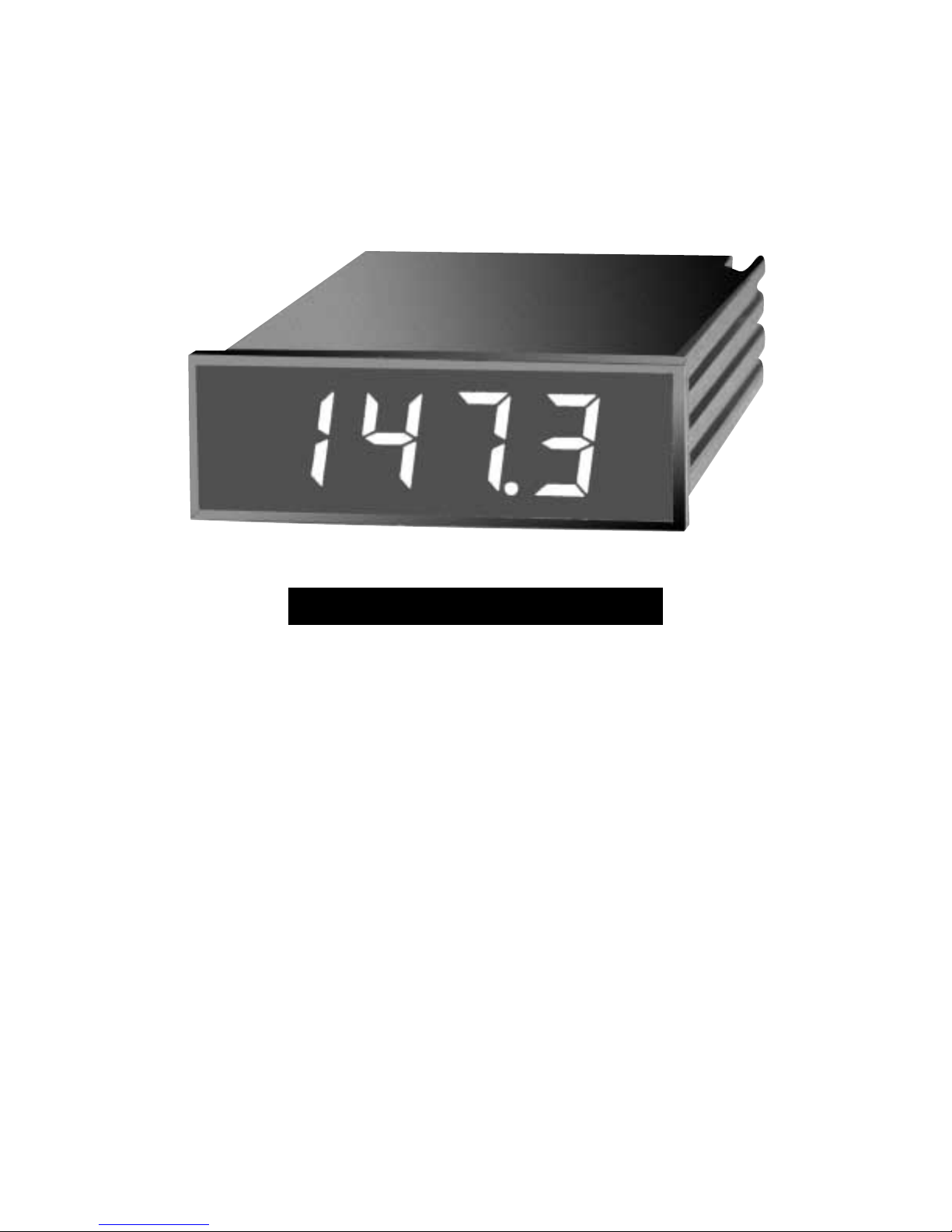
2.1 Front of the Meter
Figure 2-1 shows the panel thermometer.
Figure 2-1. Panel Thermometer
Features:
Display: 3 1/2 Digit, 7-Segment Red or Green LED
Full-size 14.2 mm (0.56") LED Display
Analog Output Standard
3/64 DIN Standard Panel Cutout
Removable Screw-Clamp Cable Connector
Display Hold Capability
4
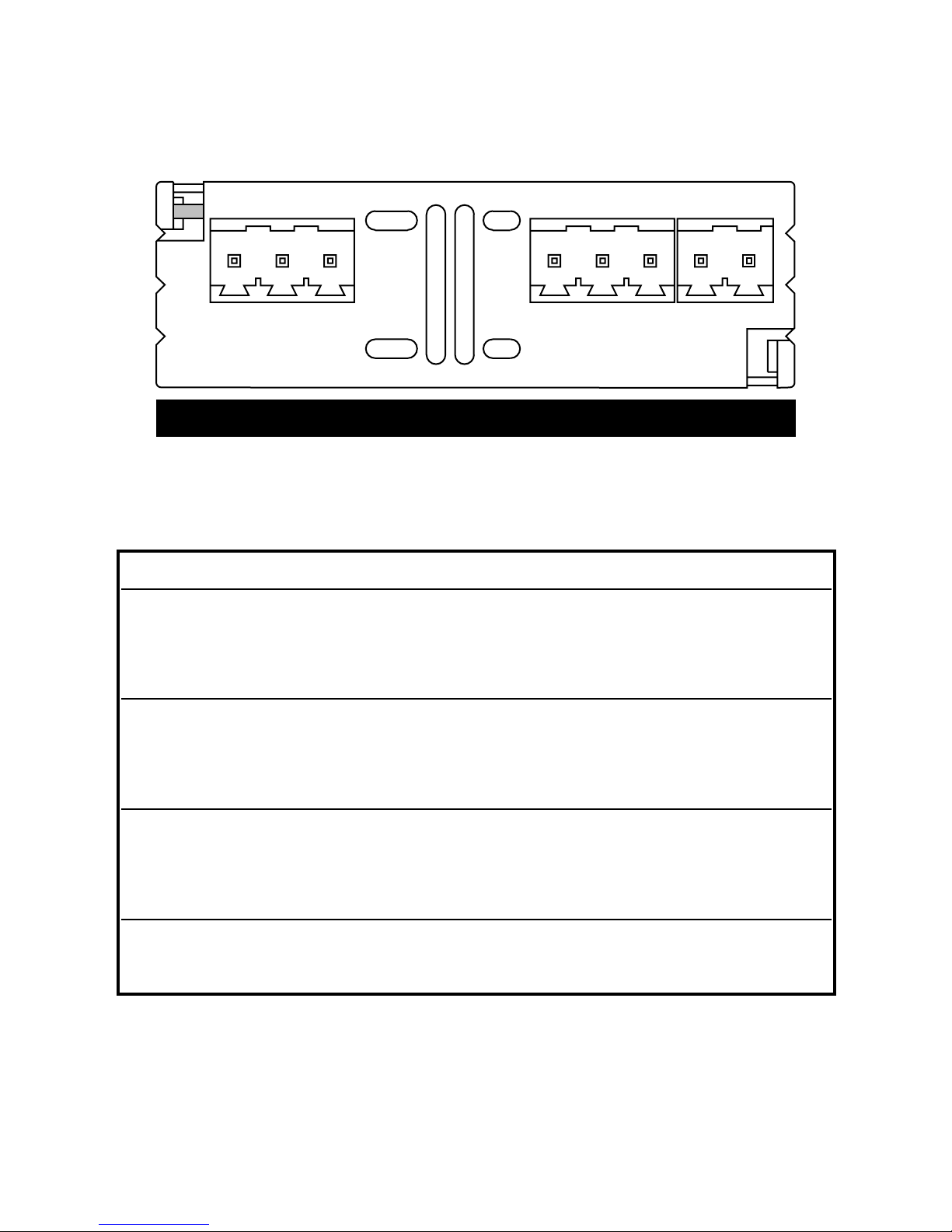
2.2 Back of the Meter
Figure 2-2 illustrates the rear of the meter.
Figure 2-2. Rear View Showing P1, P2, P3 Connectors
2.3 Connector Description
† For wire colors, refer to Table 3-1
Connector Description Connector PIN #
(AC) Earth Ground P1 1
(AC) Neutral P1 2
(AC) Line P1 3
(DC) -DC Return P1 1
(DC) +DC P1 2
(DC) No Connection (Not used) P1 3
Display Hold (Active Low) P2 1
Return P2 2
Analog Output P2 3
-TC (Neg. Lead)
†
P3 1
+TC (Pos. Lead)
†
P3 2
123 123
P1 P2 P3
12
5
SECTION 3 GETTING STARTED
3.1 Main Board Power Jumpers
Caution: The meter has no power-on switch, so it will be
in operation as soon you apply power.
The meter can be configured to operate on 115 Vac or
230 Vac by the proper combination of the soldered wire
jumpers that are located on the printed circuit board. The
meter is set at the factory to be powered by the voltage
specified at the time of ordering. The same transformer is
used for either configuration, so all you need to do is to
select the jumpers as described in this section.
Important:
These changes must be performed by a
qualified technician.
To change the Factory preset jumpers, do the following steps:
Disconnect the power from the unit before proceeding.
1. Remove the main board from the case. Refer to
Disassembly/Assembly Section 3.8.
2. Locate the solder jumpers W1, W2, and W3 (located near
the edge of the main board alongside the transformer).
3. If your power requirement is 115 Vac, solder jumpers W1
and W3 should be wired, but jumper W2 should not. If
your power requirement is 230 Vac, solder jumper W2
should be wired, but jumpers W1 and W3 should not.
 Loading...