

Page 1
1830-C
Optical Power Meter
I
NSTRUCTION
M
ANUAL
Page 2

1830-C Optical Power Meter
Page 3

Warranty
Warranty
Newport Corporation warrants this product to be free from defects in material and workmanship for a period of 1 year from the date of shipment. If
found to be defective during the warranty period, the product will either be
repaired or replaced at Newport’s option.
To exercise this warranty, write or call your local Newport representative, or
contact Newport headquarters in Irvine, California. You will be given prompt
assistance and return instructions. Send the instrument, transportation
prepaid, to the indicated service facility. Repairs will be made and the
instrument returned, transportation prepaid. Repaired products are warranted for the balance of the original warranty period, or at least 90 days.
Limitation of Warranty
This warranty does not apply to defects resulting from modification or misuse
of any product or part. This warranty also does not apply to fuses, batteries,
or damage from battery leakage.
This warranty is in lieu of all other warranties, expressed or implied, including
any implied warranty of merchantability or fitness for a particular use.
Newport Corporation shall not be liable for any indirect, special, or consequential damages.
Statement of Calibration
This instrument has been inspected and tested in accordance with specifications published by Newport Corporation.
The accuracy and calibration of this instrument and photodetector (where
applicable) is traceable to the National Institute for Standards and Technology through equipment which is calibrated at planned intervals by comparison to the certified standards maintained at Newport Corporation.
© 1994 Newport Corporation
P/N 20372-01, Rev. H
IN-07941 (07-00)
ii
ii
Page 4

EC DECLARATION OF CONFORMITY
Model 1830-C
We declare that the accompanying product, identified with the
" " mark, meets the intent of the Electromagnetic Compatibility
Directive, 89/336/EEC and Low Voltage Directive 73/23/EEC.
Compliance was demonstrated to the following specifications:
EN50081-1 EMISSIONS:
Radiated and conducted emissions per EN55011, Group 1,
Class A
EN50082-1 IMMUNITY:
Electrostatic Discharge per IEC 1000-4-2, severity level 3
Radiated Emission Immunity per IEC 1000-4-3, severity level 2
Fast Burst Transients per IEC 1000-4-4, severity level 3
Surge Immunity per IEC 1000 4-5, severity level 3
IEC SAFETY:
Safety requirements for electrical equipment specified in
IEC 1010-1.
Alain Danielo Jeff Cannon
VP European Operations General Manager-Precision Systems
Zone Industrielle 1791 Deere Avenue
45340 Beaune-la-Rolande, France Irvine, CA USA
iii
Page 5

Table of Contents
Warranty ................................................................................................................ ii
EC Declaration of Conformity .............................................................................iii
List of Figures ...................................................................................................... vii
List of Tables ....................................................................................................... vii
Safety Symbols and Terms ................................................................................ viii
Definitions ............................................................................................................. ix
Specifications......................................................................................................... x
Section 1 — General Information
1.1 System Overview ...................................................................................... 1
1.2 Scope of this Manual ................................................................................ 2
1.3 Unpacking and Inspection ....................................................................... 2
1.4 Preparation for Use .................................................................................. 2
Section 2 — Initial Setup
2.1 Introduction .............................................................................................. 3
2.2 Setting the Line Voltage Selector Switch ............................................... 3
2.3 Detector Connection and Setup ............................................................. 4
2.4 Configuring the Computer Interface ...................................................... 4
2.5 Power Up / Auto-Calibration ................................................................... 5
Section 3 — System Operation
3.1 Introduction .............................................................................................. 6
3.2 Digital Display ........................................................................................... 6
3.3 Front Panel Key Functions ...................................................................... 8
3.3.1 LOCAL (R/S) Local Mode & Run / Stop ......................................... 9
3.3.2 ZERO Offset Subtraction .................................................... 9
3.3.3 UNITS Display Units ............................................................. 9
3.3.4 STOREF Store Reference Value ........................................... 10
3.3.5 AVG Numerical Averaging ............................................. 10
3.3.6 λ䉱 Wavelength Increment .......................................... 10
3.3.7 λ䉲 Wavelength Decrement ......................................... 11
3.3.8 Power ....................................................................... 11
3.3.9 ATTN Optical Attenuator ................................................. 11
3.3.10 BKLT Backlight .................................................................. 11
3.3.11 BEEP Audible Beeper ....................................................... 11
3.3.12 AUTO Automatic Gain Ranging ........................................ 11
3.3.13 RANGE䉱 Manual Range Up ................................................... 12
3.3.14 RANGE䉲 Manual Range Down .............................................. 12
3.4 Default Meter Configuration.................................................................. 12
iv
Page 6

Section 4 — Performing Measurements
4.1 Introduction ............................................................................................ 13
4.2 Photodetector Considerations ............................................................. 13
4.2.1 Detector Calibration and Accuracy............................................ 13
4.2.2 Quantum Detector Temperature Effects ................................... 14
4.2.3 Ambient and Stray Light .............................................................. 14
4.3 Setting the Wavelength .......................................................................... 15
4.4 Setting the Attenuator Mode ................................................................. 15
4.5 Performing Basic Measurements.......................................................... 16
4.5.1 Power Measurements .................................................................. 16
4.5.2 Logarithmic Measurements (dB and dBm) ............................... 16
4.5.2.1 Logarithmic Measurements Using Reference Powers (dB) . 17
4.5.2.2 Logarithmic Measurements Using 1 mW Reference (dBm) . 17
4.5.3 Relative Measurements ............................................................... 18
4.6 Common Measurement Errors ............................................................. 19
Section 5 — Computer Interfacing
5.1 Introduction ............................................................................................ 20
5.2 Computer Interface Terminology ......................................................... 20
5.3 Entering Remote Computer Interface Mode ....................................... 21
5.4 RS-232C Communication........................................................................ 22
5.4.1 Setting the Baud Rate .................................................................. 23
5.4.2 RS-232C Command Termination ................................................. 23
5.4.3 General Guidelines for Using the RS-232C Port ........................ 24
5.5 GPIB Communication ............................................................................. 24
5.5.1 Setting the GPIB Address ............................................................ 24
5.5.2 GPIB Command Termination ...................................................... 25
5.5.3 General Guidelines for Using the GPIB Port ............................. 26
5.5.4 Procedure for Reading Only New Measurements .................... 26
v
Page 7

Section 6 — Remote Command Set
6.1 Summary of Command/Query Set ........................................................ 27
6.2 Detailed Description of Commands and Queries ............................... 29
An Attenuator on/off ................................................................ 29
A? Attenuator query................................................................. 29
Bn Beeper on/off ........................................................................ 30
B? Beeper query ....................................................................... 30
C Clear Status Byte Register .................................................. 30
D? Data query............................................................................ 31
En Echo mode on/off—( RS-232C interface only) .................. 31
E? Echo mode query ................................................................ 31
Fn Filter ( same as averaging ) Slow, Medium, Fast .............. 32
F? Filter (same as averaging) status query .......................... 32
Gn Go on/off (Run/Stop signal acquistition) .......................... 33
G? Go query ............................................................................... 33
Kn Keypad / Display Backlight on/off ..................................... 34
K? Keypad / Display Backlight intensity level query ............ 34
Ln Local-lockout on/off ............................................................. 35
L? Local-lockout query ............................................................ 35
Mn Service Request Enable Register (mask) .......................... 36
M? Service Request Enable Register query ............................ 37
O Auto-Calibration ................................................................... 37
Q? Status Byte Register query ................................................. 38
Rn Range setting ........................................................................ 39
R? Range query .......................................................................... 40
S Store reference ..................................................................... 40
Un Units....................................................................................... 41
U? Units query ........................................................................... 41
Wnnnn Set wavelength to nnnn ....................................................... 42
W? Wavelength query ................................................................ 42
Zn Zero on/off ............................................................................ 43
Z? Zero function query ............................................................. 43
Section 7 — Troubleshooting and Maintenance
7.1 Troubleshooting Guide .......................................................................... 44
7.2 Cleaning Procedure ................................................................................ 45
7.3 Re-Calibration Schedule ........................................................................ 45
Section 8 — Factory Service
8.1 Introduction ............................................................................................ 46
8.2 Obtaining Service ................................................................................... 46
Appendices
A Status Reporting System ....................................................................... 49
B Sample Programs .................................................................................... 52
B.1 Example Program for RS-232C Communication ....................... 52
B.2 Example Program for IEEE 488 Communication ...................... 55
C Simplified 1830-C Functional Block Diagram....................................... 58
vi
Page 8

List of Figures
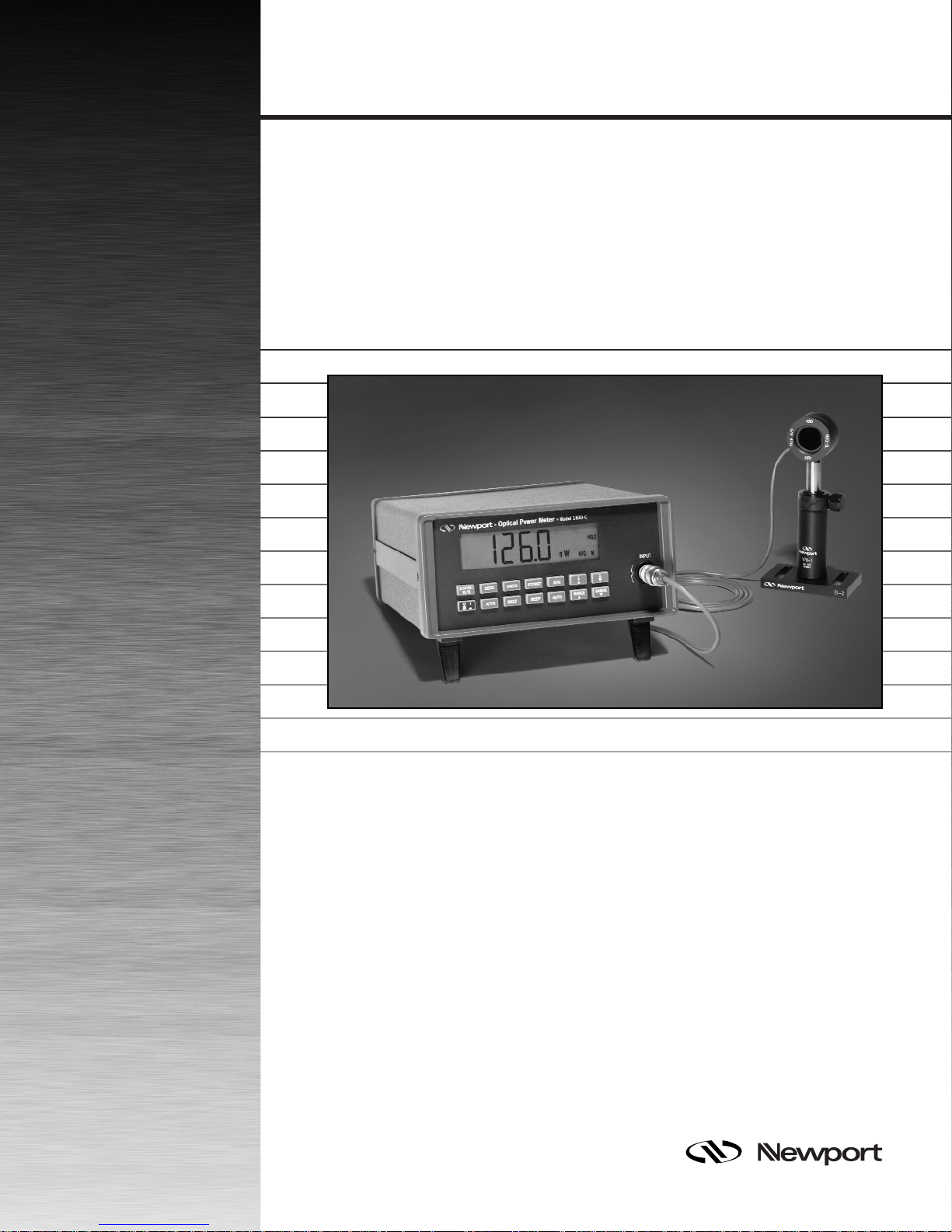
1. 1830-C Power Meter and Compatible Detectors................................... 1
2. Line Voltage Selector Switch................................................................... 3
3. Connecting a Detector with its Calibration Module............................. 4
4. Calibration Module Connector Port ....................................................... 4
5. The 1830-C Liquid Crystal Display ......................................................... 6
6. Front Panel Key Pad ................................................................................. 8
7. RS-232C Cable Connections................................................................... 22
8. RS-232C Baud Rate Selector Switches.................................................. 23
9. GPIB Address Selector Switches .......................................................... 25
10. The 1830-C’s Status Reporting System for the GPIB Bus ................... 49
11. Simplified Functional Block Diagram ................................................... 58
List of Tables
1. Measurement Modes ................................................................................ x
2. 1830-C Display Annunciators/Messages ................................................ 7
3. 1830-C Key Functions and Associated Remote Commands ................ 8
4. 1830-C Default Power-up Conditions.................................................... 12
5. Common Measurement Errors ............................................................. 19
6. Symptom/Fault Troubleshooting Guide .............................................. 45
vii
Page 9

Safety Symbols and Terms
The following safety terms are used in this manual:
The WARNING heading in this manual explains dangers that could result in
personal injury or death.
The CAUTION heading in this manual explains hazards that could damage
the instrument.
In addition, a NOTES heading gives information to the user that may be
beneficial in the use of this instrument.
GENERAL WARNINGS AND CAUTIONS
The following general warnings and cautions are applicable to this instrument:
This instrument is intended for use by qualified personnel who recog-
nize shock hazards or laser hazards and are familiar with safety
precautions required to avoid possible injury. Read the instruction
manual thoroughly before using, to become familiar with the
instrument’s operations and capabilities.
WARNING
WARNING
The American National Safety Institute (ANSI) states that a shock
hazard exists when probes or sensors are exposed to voltage levels
greater than 42VDC or 42V peak AC. Do not exceed 42V between any
portion of the Model 1830-C (or any attached detector or probe) and
earth ground or a shock hazard will result.
CAUTION
There are no user serviceable parts inside the Model 1830-C. Work
performed by persons not authorized by Newport may void the
warranty. For instructions on obtaining warranty repair or service
please refer to Section 8 of this manual.
viii
Page 10

Definitions
A amps
ADC analog-to-digital converter
BNC standard coaxial connector type
degree C degrees Centigrade
Hz Hertz (cycles per second)
k kilo (103)
kHz kilohertz
kΩ kilo-ohms
µ micro (10
m milli (10-3)
mA milliamps
mV millivolts
n nano (10-9)
nA nanoamps
nm nanometers
RH relative humidity
S/N serial number
µA microamps
µs microseconds
V volts
W watts
--6
)
ix
Page 11

Specifications
Dimensions: 3.7 x 7.5 x 9.0 in. (94 x 191 x 229 mm )
Weight: 5 lb ( 2.3 kg )
Enclosure: Metal case, painted
Connectors: Calibration Module: 8-Pin Sub Mini DIN
Analog Output: BNC
RS-232: 9 pin D-Sub
GPIB: 24 Conductor D
Power : 100-120, 220-240 VAC ±10%, 50/60 Hz
Absolute Maximum Line
Current Rating: 200 mA
Signal Ranges: Up to 8 decades (dependent on detector type)
Display: 4.5 digit, annunciated, backlit, wide angle view LCD
Display Update Rate: 75 ms
Auto-Ranging Time: 200 ms (typical)
GPIB Bus Transfer Time: 10 ms (typical)
Operating Environment: 0 to +40 degree C; < 70% RH noncondensing
Storage Environment: −20 to +60 degree C; < 90% RH noncondensing
Compatible Detectors: Low-Power (Semiconductor) Family
Signal Range
Full-Scale Current
1, 2
12345678
3
2 nA 20 nA 200 nA 2 µA 20 µA 200 µA 2 mA 5 mA
Gain 1000 M 100 M 10 M 1 M 100 k 10 k 1 k 100
Resolution 0.1 pA 1 pA 10 pA 100 pA 1 nA 10 nA 100 nA 1 µA
Analog Bandwidth 35 Hz 35 Hz 1.5 kHz 1.5 kHz 5 kHz 15 kHz 10 kHz 20 kHz
Full-Scale Accuracy
4
0.2 % 0.2 % 0.2 % 0.2 % 0.2 % 0.2 % 0.2 % 0.2 %
(Typical)
Full-Scale Accuracy
4
0.4 % 0.4 % 0.4 % 0.4 % 0.4 % 0.4 % 0.4 % 0.4 %
(Worst Case)
1
Listed signal ranges specify meter capability. Available signal ranges are detector dependent.
2
Maximum measurable signal is detector dependent. See description of detector saturation message “SA” in Table 2.
3
Full scale current may vary due to the Auto-Calibration compensation of amplifier DC offsets.
4
After 60 minute warm-up, followed by execution of an Auto-Calibration. See Section 2.5 and Section 6.2 (“O” Command).
Analog Output
Full-Scale Voltage: 2V into 1MΩ
Full-Scale Accuracy: ±1%
Maximum AC Noise: Range 1: <4 mV
(open input) Ranges 2-8: <1 mV
p-p
p-p
x
Page 12

Display Display
Calculation Unit Comment
I/R W ZERO Disabled
(I-Iz)/R W ZERO Enabled
101log
/IR
mW
dBm ZERO Disabled
(
101log
10 log
I
STOREF
10 log
II
STOREF Z
I
I
STOREF
II
−
Z
II
−
STOREF Z
−
Z
mW
I
−
II
/II R
)
Z
−
dBm ZERO Enabled
dB ZERO Disabled
dB ZERO Enabled
REL ZERO Disabled
REL ZERO Enabled
Where I = detector current
Iz= detector background current defined when the
ZERO key was pressed
R = responsivity of the detector (A/W)
I
STOREF
= referenced detector current defined when the
STOREF key was pressed
Table 1. Measurement Modes
xi
Page 13

xii
Page 14
Section 1
General Information
1.1 System Overview
The 1830-C Optical Power Meter is a ±20,000 count A/D resolution, autoranging picoammeter. Measurements are displayed on a large 4 1/2 digit
liquid crystal display (LCD) and can also be taken remotely via the RS-232C
port or the IEEE 488 GPIB bus. The 1830-C is designed to take continuous
wave optical power measurements and is compatible with all of Newport’s
Low-Power Semiconductor photodetectors. A family tree of the 1830-C
compatible detectors and accessories is shown in Figure 1 below.
FP3-FH1
818-FA2
818-UV/CM
818-SL/CM
818-IR/CM
818-FA3-SMA
818-FA3-ST
818-FA3-FC
818-F-SL
818-F-IR
■
Optical Power Meter ■
Model 1830-C
(LOCAL)
R/S
AVG
STOREF
UNITSZERO
BEEPBKLT
ATTN
AUTO
INPUT
RANGEλλRANGE
818-ST/CM
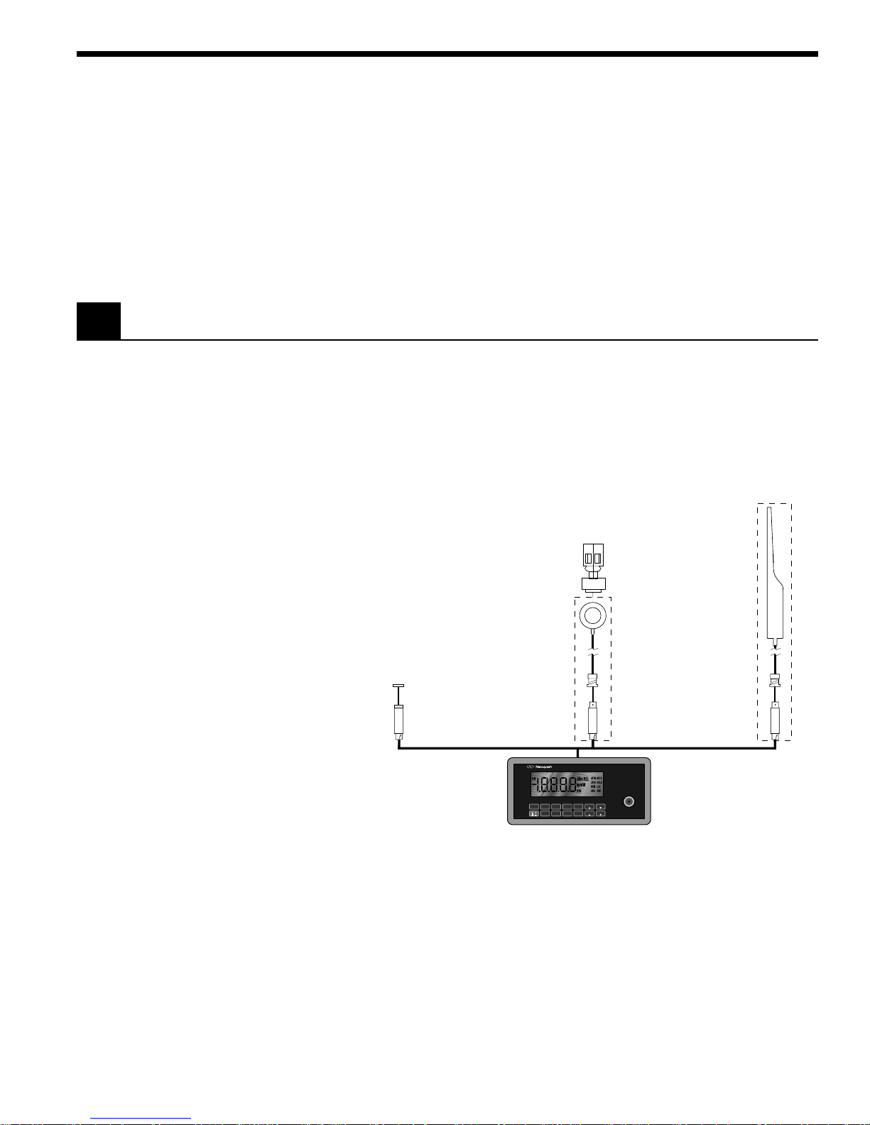
Figure 1. 1830-C Power Meter and Compatible Detectors
Detectors connect to the 1830-C through a calibration module, in which the
responsivities and other information unique to the detectors is stored.
Calibration modules are ordered with the detectors at the time of purchase
and are labeled with the detectors’ model number and serial number.
Detectors with calibration modules have a “/CM” appended to their model
number.
EXAMPLE: 818-SL (no calibration module)
818-SL/CM (with calibration module)
1
Page 15

1.2 Scope of this Manual
1.3 Unpacking and Inspection
Please carefully read this instruction manual before using the 1830-C. Be
especially careful to observe the warnings and cautions throughout this
manual (see Safety Symbols and Terms). If any operating instructions are
not clear, contact Newport Corporation.
This instruction manual contains the necessary information for operation
and maintenance of the 1830-C, as well as information for troubleshooting
and obtaining service if necessary. This information is divided into the
following sections:
Section 1 General Information
Section 2 Initial Setup
Section 3 System Operation
Section 4 Performing Measurements
Section 5 Computer Interfacing
Section 6 Remote Command Set
Section 7 Troubleshooting and Maintenance
Section 8 Factory Service
1.4 Preparation for Use
All 1830-C meters are carefully assembled, tested and inspected before
shipment. Upon receiving this instrument, check for any obvious signs of
physical damage that might have occurred during shipment. Report any
such damage to the shipping agent immediately.
NOTE
Retain the original packing materials in case reshipment becomes necessary.
The 1830-C should have some basic operations performed before measurements are made. These include:
Setting the Line Voltage Selector Switch ( Section 2.2)
Detector Connection and Setup ( Section 2.3)
2
Page 16

Section 2
LINE SELECT
230V
115 V
100–120V 50–60 Hz, 0.25A, SLO- BLO, 250V
220–240V 50–60 Hz, 0.25A, SLO- BLO, 250V
FUSE
Initial Setup
2.1 Introduction
This section contains information on how to configure the 1830-C to your
local line voltage and how to connect the detector and calibration module
to the meter. It also includes a short discussion about the remote interface
and the 1830-C’s power-up and auto-calibration.
2.2 Setting the Line Voltage Selector Switch
The 1830-C can be configured to operate with line voltages of 100-120 VAC
and 220-240 VAC, and line frequencies between 50-60 Hz. Before turning the
meter on, configure it to the local voltage by setting the voltage selection
switches on the 1830-C back panel to match the nominal local voltage. See
Figure 2. Plug the AC line power cord to the rear of the 1830-C and then
connect the cord to AC power.
Figure 2. Line Voltage Selection Switch
WARNING
This product is equipped with a 3 wire grounding type plug. Any
interruption of the grounding connection can create an electric shock
hazard. If you are unable to insert the plug into your wall plug receptacle, contact your electrician to perform the necessary alterations to
assure that the green (green-yellow) wire is attached to earth ground.
3
Page 17
2.3 Detector Connection and Setup
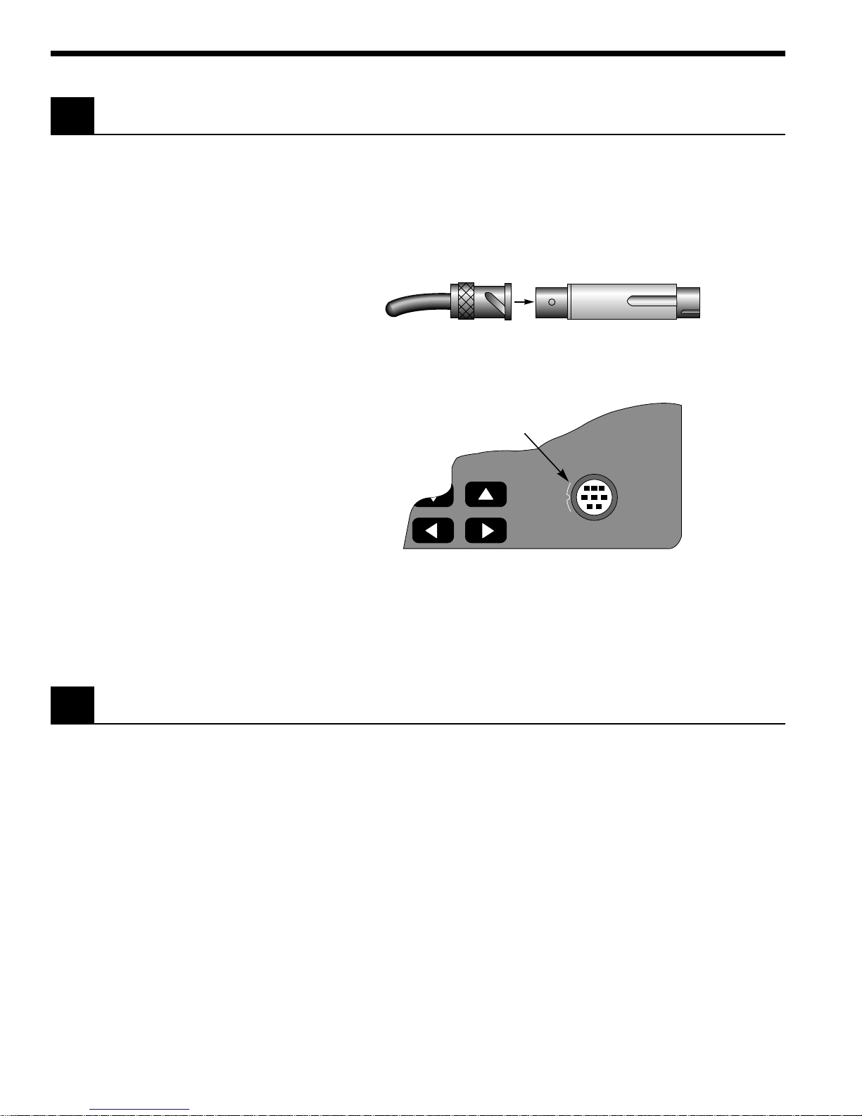
Connect the detector to its calibration module as shown in Figure 3. The
detector’s model and serial numbers must match the model and serial
numbers found on the calibration module. Insert the calibration module,
with its groove facing left, into the connector port on the front panel of the
1830-C, as shown in Figure 4. An alignment pin assures the proper orientation of the calibration module.
Detector Cable BNC Calibration Module
Figure 3. Connecting a Detector with its Calibration Module
Plug calibration
module into this port.
INPUT
Always power off the meter before removing or inserting the calibration
module.
2.4 Configuring the Computer Interface
The RS-232C baud rate and the IEEE 488 GPIB address must be properly set
via the back panel system switches if either interface is to be used. Please
refer to Section 6 for detailed instructions.
Figure 4. Calibration Module Connector Port
NOTE
4
Page 18

2.5 Power Up / Auto Calibration
Turn on the 1830-C by depressing the red power switch, located in the lower
left-hand corner of the front panel, until it clicks and remains in its depressed
position. At power-up, the 1830-C will perform the following sequence:
1) Momentarily display all the segments on the display
2) Display the software version number
3) Perform an Auto-Calibration, designated by displaying CAL on the
4) Display the serial number of the detector/calibration module
5) Display the wavelength to which the meter is set (If no calibration
The auto-calibration process involves measuring amplifier offset voltages
which arise from aging and temperature effects. These offsets are then
appropriately corrected for during normal operation. The 1830-C will
automatically disconnect the input signal from the amplifier during the
auto-calibration mode. To achieve stable readings at the specified accuracy, auto-calibration should be executed after a minimum 60 minute warmup period. This can be done either by resetting the 1830-C with the RESET
button on the back of the meter, or by sending the auto-calibration remote
command, O.
display
(If no calibration module is installed, the meter will display 000 as the
serial number.)
module is installed, the meter will display 0257nm as the wavelength.)
NOTE
The 1830-C must be powered-up with the calibration module connected to
the meter in order for the calibration data to be downloaded into the 1830-C.
Always power off the meter before removing or inserting the calibration
module.
5
Page 19
Section 3
System Operation
3.1 Introduction
3.2 Digital Display
This section contains the information needed to operate the 1830-C power
meter, via the front panel key pad. The meanings of the display annunciators and the operation of all keys are discussed later in this section.
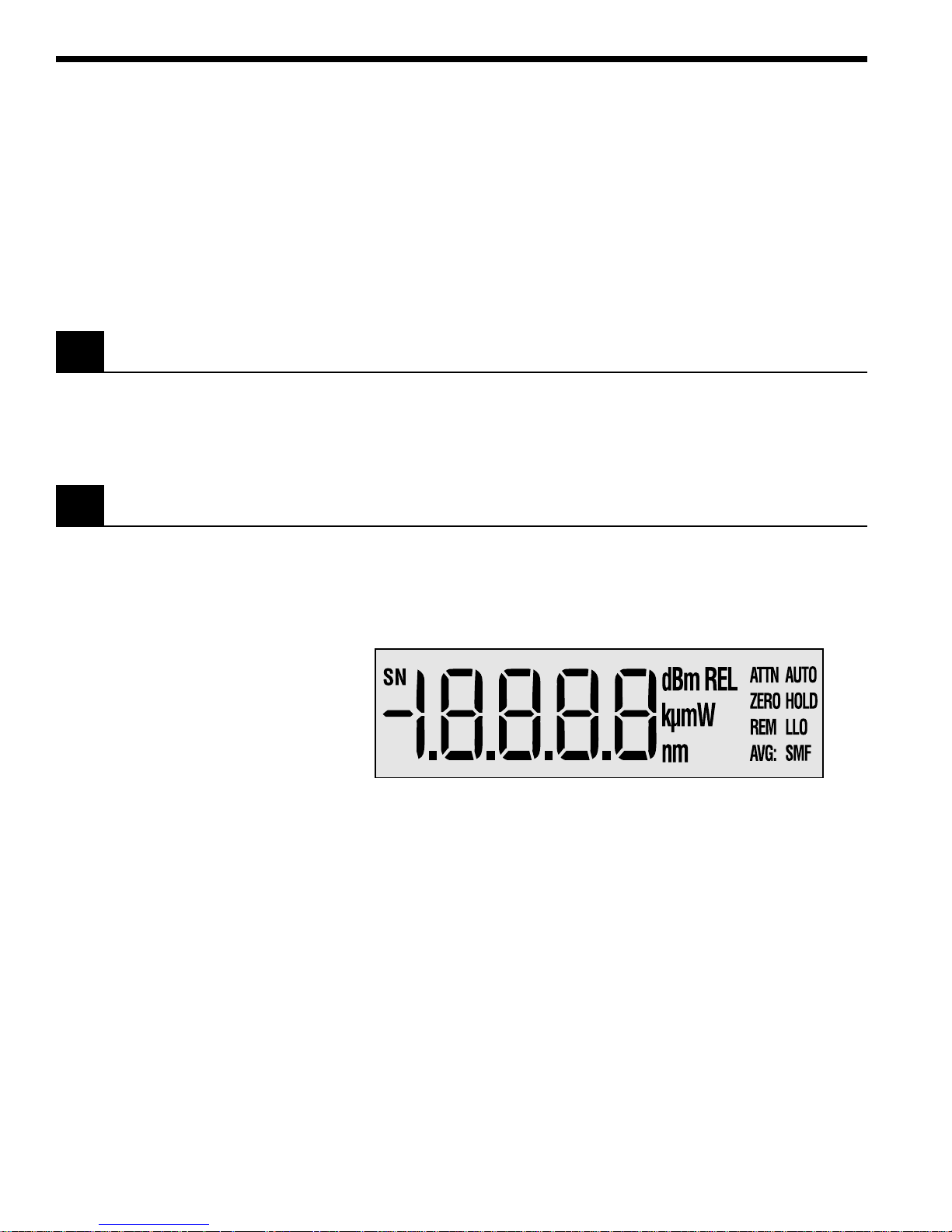
The 1830-C has a large 4-1/2 digit, back-lit liquid crystal display (LCD)
which can be seen at large angles of view. Figure 5 illustrates the layout of
the 1830-C’s display. Table 2, on the following page, explains the meaning of
the various annunciators and messages on the display.
Figure 5. The 1830-C Liquid Crystal Display
6
Page 20

Annunciator/Message Comment
SN This annunciator denotes serial number and is displayed at turn-on when
the detector’s serial number is displayed.
dBm This annunciator specifies that either dB or dBm measurements are being
displayed.
REL This annunciator specifies that relative measurements are being displayed.
k µ m Only one of the characters of this annunciator will light at any time to specify
engineering prefixes of kilo, micro, nano, or milli. The “m” in this annunciator
serves as both “m” and “n”.
W This annunciator specifies that measurements in units of watts are being
displayed.
nm This annunciator indicates nanometer whenever the wavelength is displayed.
ATTN The responsivity in use includes the effect of the detector’s OD3 attenuator.
AUTO Automatic signal ranging is activated.
ZERO Background signal subtraction (zeroing) is activated.
HOLD No new readings will be displayed, nor be available on the remote interface bus.
REM The meter has received a command/query either through the IEEE 488 or
the RS-232C bus.
LLO The meter has been set to local-lockout from the remote interface bus and
will not respond to any front panel keys.
AVG: S M F Either Slow, Medium, or Fast numerical averaging for the displayed
measurement is activated.
OL This message indicates that the input signal level exceeds the capability of
the present signal range. Either use auto-ranging or increment the signal
range until the OL message goes away.
SA This message indicates that the input signal level exceeds the specified
saturation current of the detector being used with the meter. This level is
detector dependent.
CAL This message indicates that the meter is currently performing an auto-
calibration. The auto-calibration process involves measuring amplifier offset
voltages. See Section 2.5 for more details.
Table 2. 1830-C Display Annunciators/Messages
7
Page 21
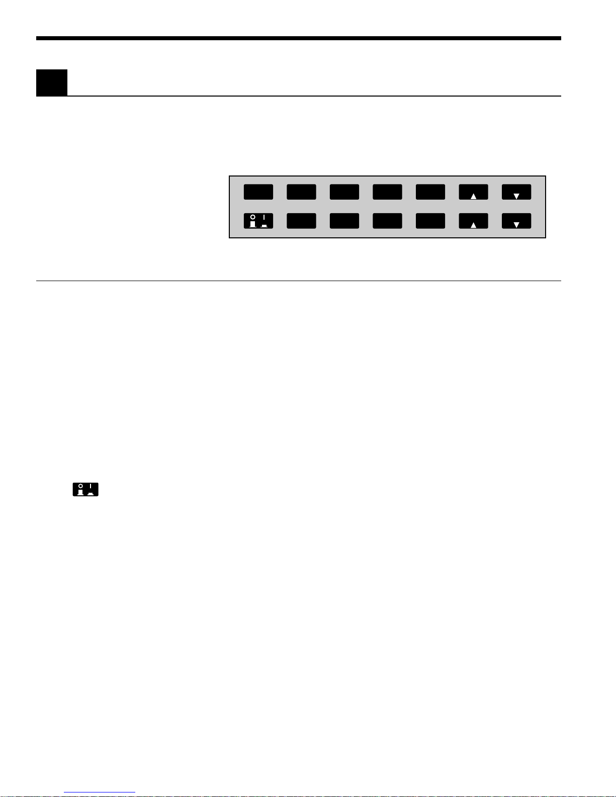
3.3 Front Panel Key Functions
The front panel key pad of the 1830-C, Figure 6, provides access to all the
basic measurement functions. Table 3 and Sections 3.3.1 through 3.3.14 list
and describe in detail each key function. For power-up default conditions,
please see Table 4 at the end of this section.
(LOCAL)
R/S
ZERO
ATTN
UNITS
BKLT
STOREF
BEEP
AVG
AUTO
RANGE RANGE
λλ
Figure 6. Front Panel Key Pad
Keypad Remote Command Description
(LOCAL) L0 Enables local mode.
R/S G0, G1 Run/Stop signal acquisition.
ZERO Z0, Z1 Zero the display by subtracting the present reading from all
subsequent readings.
UNITS U1-U4 Cycles between the four available measurement units (Watt, dB,
dBm, Relative).
STOREF S Stores last measurement for future dB or relative measure-
ments.
AVG F1-F3 Cycles between Slow, Medium, or Fast numerical averaging of
readings that are within a certain percentage of each other.
λ 䉱 Wnnnn Increments the calibration wavelength in use.
λ 䉲 Wnnnn Decrements the calibration wavelength in use.
None Turns the meter on/off.
ATTN A0, A1 Sets the responsivity value for either:
BKLT K0, K1, K2 Cycles the display backlight brightness between Off, Medium,
BEEP B0, B1 Turns the variable frequency beeper on/off.
AUTO R0, R1-R8 Turns the automatic signal ranging on/off.
RANGE 䉱 Rx Increments the signal range and disables the automatic signal
RANGE 䉲 Rx Decrements the signal range and disables the automatic signal
Table 3. 1830-C Key Functions and Associated Remote Commands
1) detector alone, or
2) detector and OD3 optical attenuator.
or High.
ranging.
ranging.
8
Page 22

3.3.1
(LOCAL)
R/S
Local Mode
Run / Stop
This key serves two purposes:
1) When the meter receives a command through either the RS-232C or the
IEEE 488 GPIB interface, the meter is automatically put into remote
mode and the REM annunciator is displayed. Now all front panel keys
are disabled except this (LOCAL) key which, when pressed, puts the
meter back into the local mode. The meter can also be put in the local
mode by sending the remote command, L0.
2) When the meter is in the local mode, pressing this key will toggle
between run/stop acquisition modes. The HOLD annunciator is displayed when the meter is in the stop acquisition mode.
3.3.2
ZERO
Offset Subtraction
This key turns the offset subtraction on and off. When turned on, the ZERO
annunciator is displayed and the last measurement is saved as Pz and
subtracted from all subsequent measurements P. This causes subsequent
measurement calculations shown on the display and available on the
remote interface to use the value ( P− Pz) instead of P.
Offset subtraction allows one to remove the effects of ambient DC signals,
by zeroing the display before making a measurement. A second ZERO key
press turns off the ZERO annunciator and stops offset subtraction.
3.3.3
UNITS
Display Units
Measurements can be displayed in units of watts W, decibels dB or dBm,
and relative REL. Pressing the UNITS key repeatedly cycles the display
through these four units.
The W mode is a straightforward measurement which converts the current
from the detector into a power reading via the responsivity of the detector
at the set wavelength.
The dB mode uses the relationship dB = 10 * log( P / P
most recent measurement and P
is the reference measurement. At power-
ref
), where P is the
ref
up the reference for the dB mode is a level equivalent to 1mW. This can be
changed by pressing STOREF, which makes the most recent measurement
the new P
.
ref
The dBm mode uses the relationship dBm = 10 * log( P / 1mW ), where P is
the most recent measurement.
The REL mode uses the relationship ( P / P
measurement and P
is the reference measurement. At power-up the
ref
), where P is the most recent
ref
reference for the REL mode is a level equivalent to 1mW. This can be
changed by pressing STOREF, which makes the most recent measurement
the new P
.
ref
When the engineering prefixes n, µ, m and k are displayed in the REL
mode, they multiply the reading on the display by their appropriate
weights. For example, a display of 1.8300µ
REL
means ( P/ P
) * 10−6.
ref
9
Page 23

3.3.4
STOREF
Store Reference Value
Pressing STOREF causes the most recent measurement P to be stored as P
ref
for subsequent use in relative measurement calculations. When the units
are dB and STOREF has been pressed, the displayed value is the function
10 * log( P/P
displayed value is the ratio P/P
P
is always a power reading stored in the units of Watts. Pressing STOREF
ref
causes a new P
3.3.5
). When the units are REL and STOREF has been pressed, the
ref
to overwrite the existing P
ref
AVG
Numerical Averaging
.
ref
value.
ref
Pressing AVG causes the numerical averaging feature to cycle through
slow S, medium M, and fast F modes. The slow mode takes the last 16
measurements that are within ±9 counts of the oldest measurement and
averages them for the displayed reading. The medium mode averages the
last 4 measurements, and the fast mode does no averaging.
The averaging buffer is a sliding buffer that always maintains 16 or 4
measurements, depending on the mode. Initially the buffer is completely
filled with the same measurement, and thereafter subsequent measurements replace the older measurements in the buffer. If, at any time, a single
measurement is acquired that is not within ±9 counts of the oldest measurement, the averaging algorithm starts over, not retaining any of the
previous measurements.
3.3.6
λ
Wavelength Increment
Pressing this key once causes the wavelength to be displayed. If the key is
pressed again or held down, the wavelength will increment or scroll,
respectively.
The detector calibration module contains responsivity data at discrete
wavelengths for its associated detector. By entering the wavelength which
is being measured, the correct responsivity value is used by the 1830-C in
calculating the measured power. When a wavelength falls between two
calibration points, linear interpolation is used to approximate the true
responsivity value.
Upon the initial power-up on a new calibration module, the meter defaults
to the shortest wavelength available for that specific detector. Whenever
the calibration wavelength is changed, this new wavelength is written to the
PROM in the calibration module and is used as the default wavelength at
subsequent power-ups.
NOTE:
If the detector and calibration module are changed to a different set, the
power meter must be powered-up again to allow for the downloading of
the new calibration data into the power meter. Always remember to
power off the meter before removing or inserting the calibration module.
10
Page 24

3.3.7
Same as λ except that this key decrements the wavelength.
λ
Wavelength Decrement
3.3.8 Power
This key turns the power to the 1830-C on and off. To turn the meter on,
depress the key until it clicks. To turn the meter off, press the key again
until it clicks and rebounds to its original position.
3.3.9
This key selects whether the responsivity value for the detector-alone, or
the value for the detector-with-attenuator is used. When the attenuator
mode is on, the ATTN annunciator is lit and the responsivity value for the
detector-with-attenuator is used. When the attenuator mode is off, the
ATTN annunciator is off and the detector-alone responsivity value is used.
3.3.10
This key cycles the brightness level of the LCD backlight between off,
medium, and high.
3.3.11
This key turns the variable frequency beeper on and off. The frequency of
this tone varies as a function of the optical power being measured. The
real-time audible feedback is very helpful when trying to maximize optical
through-put.
3.3.12
This key enables and disables the auto-range feature. When auto-range is
enabled, the AUTO annunciator is displayed and the amplifier gain in the
1830-C will be automatically controlled to maximize the analog-to-digital
converter resolution. When auto-range is disabled, the AUTO annunciator
is turned off and the signal range is left in its present state. Signal ranging
can be manually controlled by the RANGE(䉱) and RANGE(䉲) keys, as
described below.
ATTN
BKLT
BEEP
AUTO
Optical Attenuator
Backlight
Audible Beeper
Automatic Signal Ranging
NOTE
The 1830-C has 8 signal ranges (R1-R8) which are one decade apart. The
ranges available are detector dependent. For example, when using the
1830-C power meter with Newport’s 818-IR, the lowest available range is
R3. This is due to the fact that this germanium detector inherently has a
large noise equivalent power (NEP).
11
Page 25

3.3.13
RANGE
Manual Range Up
This key enables the user to manually decrease the amplifier gain by one
decade, allowing the input of larger optical signals without saturating the
amplifier. If the meter is in the auto-range mode just prior to pressing this
key, the meter will be forced into the manual-range mode and the range will
be incremented.
3.3.14
This key enables the user to manually increase the amplifier gain by one
decade. If the meter is in the auto-range mode just prior to pressing this
key, the meter will be forced into the manual-range mode and the range will
be decremented.
3.4 Default Meter Configuration
Upon power-up or pressing the RESET button on the back of the meter, the
1830-C will configure itself as listed in Table 4.
RANGE
Manual Range Down
Keypad Function Default Power-Up Condition
(LOCAL) Local
R/S Signal Acquisition is on. (Run)
ZERO ZERO is off.
UNITS Watts
STOREF 1 mW
AVG Medium Averaging
λ 䉱 Lowest available, or last set wavelength
λ 䉲 Lowest available, or last set wavelength
ATTN ATTN is off. (Detector Alone)
BKLT Medium Brightness
BEEP BEEP is off
AUTO Auto-Ranging enabled
Table 4. 1830-C Default Power-Up Conditions
12
Page 26

Section 4
Performing Measurements
4.1 Introduction
This section contains detailed information on how to make various optical
power measurements with the 1830-C.
4.2 Photodetector Considerations
This section describes detector and attenuator characteristics, optical and
electrical considerations, and environmental influences on optical measurements. In general, the accuracy of measurement with the 1830-C is limited
by the calibration accuracy of the detector calibration. Making accurate
measurements of optical power is however, also dependent upon properly
setting up the 1830-C, controlling temperature and illumination conditions,
and understanding the factors that affect power measurement.
4.2.1 Detector Calibration and Accuracy
Newport Corporation calibrates its detectors using secondary standards
directly traceable to the United States National Institute of Science and
Technology (NIST). The details and accuracy of the calibration procedure
vary with each detector model but a detailed description of the calibration
results is supplied with each individually calibrated detector.
In general, detector calibration accuracy ranges from 2% to 7% in absolute
terms and varies with wavelength. Each detector will have some variation
in the response over different sections of its surface. Therefore, for the
most reproducible measurements, light should illuminate the detector as
uniformly as possible over 80% of the detector’s active area.
CAUTION
Avoid focusing a light source onto the detector surface.
Inaccurate readings and possible detector damage may result.
Consult your detector manual for information on detector
saturation or damage thresholds.
NIST traceability requires that detectors be re-calibrated on one year
intervals. As individual detector responses change with time, especially in
the ultraviolet spectral range, re-calibration is necessary to assure confidence in the accuracy of the measurement. The same detector should
always be used for measurements which are to be directly compared, in
order to obtain reproducible results.
13
Page 27

4.2.2 Quantum Detector Temperature Effects
Semiconductor based photodiode detector characteristics (Newport
Corporation Low-Power detectors) are significantly affected by temperature. At longer wavelengths, these quantum detectors typically lose sensitivity with increasing temperature. However the detector dark current
increases exponentially with temperature. For silicon detectors, dark
current is generally on the order of a few picoamps at room temperatures.
With uncooled germanium detectors, however, this dark current is on the
order of a nanoamp, or typically 1,000 to 10,000 times greater than silicon.
These dark currents can be zeroed at any moment in time via the ZERO key
on the 1830-C. Since dark currents drift with temperature, the ZERO should
be adjusted just prior to taking any measurements. The noise or drift in the
dark current sets a lower bound on the measurement resolution which can
be achieved with any given detector.
If the detector temperature is constant, sensitivity changes and dark
current drifts are significantly reduced. In addition, if the detector is
cooled, the dark current and dark current noise will decrease. For the most
accurate measurements, particularly with germanium detectors, the user
can cool the detector to approximately 0 °C and control the temperature to
within ± 1 °C.
4.2.3 Ambient and Stray Light
Ambient and stray light striking the detector will be measured by the 1830C, and should be considered when making sensitive measurements. Ambient light can be distinguished from dark current (or the detector/meter
noise floor) by turning off or blocking the source and covering the detector
face with an opaque material such as a piece of black metal. Using the
human hand to cover the detector is not advised because it emits a significant amount of infrared radiation, and because it radiates a temperature
significantly different from ambient. With the detector covered, a reading of
the dark current may be made. Next, remove the material which is covering
the detector and take another reading. The difference is the ambient light
level.
The effects of ambient light are greatly reduced when using a fiberconnectorized signal input to the detector. If free-space beam measurements are desired, using an attenuator (Low-Power detectors have an OD3
attenuator included) will reduce stray light and often improve the source
signal to ambient signal noise level. Wavelength-specific filters, such as
optical cutoff, bandpass, or spike filters can also be used if the signal
wavelength spectrum permits. Other techniques to reduce stray light
include using apertures, placing the detector in a box or other housing to
shield the surface from light which is not coming from the source, and
turning off room and other lights.
NOTE
Changes in ambient light levels can occur from such factors as
turning room lights on or off, or by moving people or equipment. Remember, if you can see your detector element, then your detector can see the
light bouncing off your shirt!
14
Page 28

4.3 Setting the Wavelength
In order to obtain accurate optical power measurements, it is necessary to
set the calibration wavelength to the wavelength of the light incident upon
the photodetector. This calibration wavelength is indicated in nanometers
on the LCD display at power-up and whenever the λ䉱/λ䉲 keys are pressed.
Upon power-up, the calibration wavelength used will be the last value
entered into the meter (if this is the initial power-up on your calibration
module, the wavelength will default to the shortest available wavelength).
To change the wavelength, do the following:
Determine the wavelength of the light being measured to the nearest
nanometer. If the source is broadband, use either a value near the center
wavelength of the light or the wavelength with greatest intensity. Pressing
the λ䉱/λ䉲 keys will increase or decrease the calibration wavelength by
1nm. Wavelength will continue to change as long as the wavelength key is
depressed.
NOTE
Different detectors are sensitive over different wavelength ranges. See the
appropriate detector manual and calibration data to determine the range
of wavelengths available for the detector being used. The responsivities
stored in the calibration module span only the wavelength range appropriate for the detector and are specific to that detector.
4.4 Setting the Attenuator Mode
All Newport detectors are provided with calibrated optical attenuators.
The responsivities for an attenuator/detector combination are stored in the
calibration module. To measure optical powers above the saturation limit
of the detector (see appropriate photodetector manual), use the optical
attenuator that was shipped with your detector. When the attenuator mode
is selected, the following occurs:
a. The ATTN annunciator is displayed.
b. The responsivity for the detector-with-attenuator is used in calculating
If the attenuator is subsequently removed, the ATTN key should be pressed
to turn the attenuator mode off. All measurements will now be computed
using the responsivity for the detector-alone.
The transmission characteristics of each attenuator are slightly different;
the user must therefore be careful to use ONLY the attenuator and detector pair with the same serial numbers for which the particular calibration
module is calibrated.
the optical power being measured.
NOTE
15
Page 29

4.5 Performing Basic Measurements
4.5.1 Power Measurements
The 1830-C’s most basic measurement mode is in the units of Watts.
Power measurements may be made with background correction, which is
initiated by pressing the ZERO key. The following equation illustrates this
relationship:
a. Select the Watt measurement mode, auto-range, and a wavelength. Use
manual ranging if you want manual control of the range; over-range is
indicated by an OL message.
Watt reading = Net Applied Power
= ( I - Iz ) / R
where
I = detector input current
Iz= detector background current defined
when the ZERO key was pressed
R = responsivity of the detector (A/W)
(or detector with attenuator)
b. Block the light to be measured.
c. Initiate background correction by pressing the ZERO key. Display
should read approximately zero, but will fluctuate depending upon the
variations in the amount of light reaching the detector and the detector
dark current fluctuations.
d. Illuminate the detector with the optical signal to be measured.
e. Take the reading from the display.
4.5.2 Logarithmic Measurements (dB and dBm)
The 1830-C can make logarithmic measurements referenced to any measured power level or to a 1 mW power level by changing the measurement
units to dB or dBm, respectively.
NOTE
Log measurements should always be made on the lowest possible range
(without over-ranging). Readings on high ranges will not allow optimum
calculations of the logarithm. When in doubt, use auto-range.
NOTE
When using log measurements with background correction, the signal after
the subtraction of the stored offset power level may be negative. In this
case, OL will be displayed since the log of a negative number is not defined.
This will be automatically cleared when the signal becomes positive.
16
Page 30

4.5.2.1 Logarithmic Measurements Using Reference Powers (dB)
The dB measurement mode displays the absolute value of 10 times the
logarithm (base 10) of the input power, referenced to a power level which
is selected by pressing the STOREF key. The following equation illustrates
this relationship:
dB reading = 10 * log [Net Applied Power/Net Referenced
Power(=STOREF)]
= 10 * log [(( I - Iz )/R)/((I
STOREF
- IZ)/R)]
where
I = detector input current
Iz= detector background current defined when
the ZERO key was pressed
I
= referenced detector current defined when the
STOREF
STOREF key was pressed
R = responsivity of the detector (A/W)
(or detector with attenuator)
To make dB measurements with background correction, proceed as follows:
a. Select the dB measurement mode, auto-range, and a wavelength.
b. Block the light to be measured.
c. Initiate background correction by pressing the ZERO key. Display
should read approximately zero, but will fluctuate depending upon the
variations in the amount of light reaching the detector and the detector
dark current fluctuations.
d. Illuminate the detector with the optical signal to be used as the
reference signal.
e. Press the STOREF key.
f. Illuminate the detector with the optical signal to be measured.
g. Take the reading from the display.
4.5.2.2 Logarithmic Measurements Using 1 mW Reference (dBm)
The dBm measurement mode displays the absolute value of 10 times the
logarithm (base 10) of the input power, referenced to 1mW. The following
equation illustrates this relationship:
dBm reading = 10 * log [Net Applied Power/1mW]
= 10 * log [(( I - Iz )/R)/1 mW]
where
I = detector input current
Iz= detector background current defined when
the ZERO key was pressed
R = responsivity of the detector (A/W)
(or detector with attenuator)
Using this 1mW reference power, the dBm reading span is from −90 dBm to
+10 dBm (1 pW to 10 mW), when the detector responsivity equals 1.
17
Page 31

To make dBm measurements (relative to 1 mW optical power) with background correction, proceed as follows:
a. Select the dBm measurement mode, auto-range, and a wavelength.
b. Block the light to be measured.
c. Initiate background correction by pressing the ZERO key. Display
should read approximately zero, but will fluctuate depending upon the
variations in the amount of light reaching the detector and the detector
dark current fluctuations.
d. Illuminate the detector with the optical signal to be measured.
e. Take the reading from the display.
4.5.3 Relative Measurements
The relative mode REL is selected by pressing the UNITS key until the REL
annunciator turns on. The referenced power is selected at any time by pressing the STOREF key. The following equation illustrates this relationship:
REL reading = Net Applied Power/ Net
Referenced Power(=STOREF)
= (( I - Iz)/R)/((I
STOREF
- IZ)/R)
where
I = detector input current
Iz= detector background current defined
when the ZERO key was pressed
I
= referenced detector current defined when
STOREF
the STOREF key was pressed
R = responsivity of the detector (A/W)
(or detector with attenuator)
To make relative measurements with background correction, proceed as
follows:
a. Select the REL measurement mode, auto-range, and a wavelength.
b. Block the light to be measured.
c. Select background correction by pressing the ZERO key. Display should
read approximately zero, but will fluctuate depending upon the variations in the amount of light reaching the detector and the detector dark
current fluctuations.
d. Illuminate the detector with the optical signal to be used as the
reference signal.
e. Press the STOREF key.
f. Illuminate the detector with the optical signal to be measured.
g. Take the reading from the display.
18
Page 32

4.6 Common Measurement Errors
The most common sources of optical power measurement errors are listed
in Table 5 below.
Type of Error What should be done?
Radiometry Check that all of the light is actually hitting the
Ambient Light Check that any ambient light was ZERO’ed
Wavelength Calibration Check that the proper wavelength has been set.
Detector Saturation Check that the optical power density remains
Meter Configuration Check that the 1830-C was powered-up with the
detector.
before the measurement was made.
below the detector’s saturation threshold.
calibration module properly connected.
Check that the optical attenuator mode (ATTN
annunciator) is properly enabled/disabled.
Table 5 — Common Measurement Errors
19
Page 33

Section 5
Computer Interfacing
5.1 Introduction
The 1830-C has two computer interface ports: GPIB and RS-232C. The GPIB
interface conforms with the IEEE 488.1 hardware standard. All commands
for the 1830-C are device dependent commands. In this manual, we interchangeably use either GPIB or IEEE 488 when referring to the IEEE 488 bus.
Please see the General Guidelines sections for using either the GPIB
(Section 5.5.3) or RS-232C (Section 5.4.3) interfaces. These sections
include important information on using these interfaces properly.
5.2 Computer Interface Terminology
Key abbreviations and concepts used in the command reference section of
this manual are listed below:
<EOI> End or Identify
An IEEE488.1 signal sent with the end-of-string character.
<CR> Carriage Return
The ASCII decimal “13” byte.
<LF> Line Feed
An ASCII decimal “10” byte.
<NL> New Line
Defined in the IEEE 488 standard as the ASCII decimal “10” byte.
20
Page 34

<SRQ> Service Request
The 1830-C generates an <SRQ> to tell the GPIB controller that a serial poll
is needed. Any device on the GPIB bus may assert the <SRQ> line. Bit 6
(decimal 64) will be high in the serial poll byte returned from a device
requesting service. To determine if a device has generated an SRQ, an
“AND” operation could be performed on the Status Byte :
IF ((serial poll) AND 64) = 64 THEN ⇒ device is requesting service,
where serial poll is the integer returned from a GPIB serial poll.
Whitespace
Optional between commands and between parameters. Whitespace is any
character with a binary value less than or equal to an ASCII space character
( except the <NL> character ).
Numerical types
Numerical parameters are passed and returned as the actual ASCII characters in the string representation of the number. The 1830-C accepts numeric values in decimal format only.
RS-232C Command Termination
Commands and queries sent to the 1830-C through the RS-232C port should
be terminated with a <LF>.
All responses sent by the 1830-C are terminated with a <LF>.
GPIB Command Termination
Commands and queries sent to the 1830-C through the GPIB must be
terminated with a <NL> <EOI> (<NL> is equivalent to an <LF>).
All responses sent by the 1830-C are terminated with a <NL> <EOI>.
5.3 Entering Remote Computer Interface Mode
When a command or query is received by the GPIB or RS-232C interface
ports, the 1830-C automatically goes into the remote interface mode. The
REM annunciator on the 1830-C display will light up to indicate that the
1830-C is in remote interface mode.
When in remote mode, the 1830-C can be issued a “L1” command. The LLO
annunciator on the 1830-C display will also light up to indicate that the
1830-C is in the local-lockout mode. This mode disables the 1830-C front
panel keypad from affecting system operation. Locking out the front panel
keys is useful in applications where the user does not want inadvertent key
presses to affect his application setup. “L0” command disables the locallockout feature. The local-lockout mode can also be disabled by poweringup the meter again, or by pressing the “RESET” button located at the back
of the meter.
21
Page 35

5.4 RS-232C Communication
Before communicating with 1830-C through the RS-232C port, proper cable
connections must be made. Figure 7 shows the cable connections for
communicating with the RS-232C port on the 1830-C.
TO 1835 TO COMPUTER
CABLE TERMINATORS (RS-232)
9 pin to 25 pin
9 PIN
PIN NO.
TO 1835 TO COMPUTER
CODE DESCRIPTION
1
DCD
2
RXD
3
TXD
4
DTR
5
GND
6
DSR
7
RTS
8
CTS
9
CARRIER DETECT
RECEIVE DATA
TRANSMIT DATA
DATA TERM. READY
SIGNAL GROUND
DATA SET READY
REQUEST TO SEND
CLEAR TO SEND
RI
RING IND.
25 PIN
PIN NO.
8
3
2
20
7
6
4
5
22
CABLE TERMINATORS (RS-232)
9 pin to 9 pin
9 PIN
PIN NO.
1
2
3
4
5
6
7
8
9
CODE DESCRIPTION
DCD
RXD
TXD
DTR
GND
DSR
RTS
CTS
CARRIER DETECT
RECEIVE DATA
TRANSMIT DATA
DATA TERM. READY
SIGNAL GROUND
DATA SET READY
REQUEST TO SEND
CLEAR TO SEND
RI
RING IND.
9 PIN
PIN NO.
1
2
3
4
5
6
7
8
9
Figure 7. RS-232C Cable Connectors
22
Page 36

5.4.1 Setting the Baud Rate
Once cable connections are made, the baud rate for communication must
be set. Valid baud rates are 9600, 4800, 2400 and 1200. The parity, data bits,
and stop bits are fixed at: no parity, 8 data bits, and 1 stop bit.
RS-232C Parameters
Baud Rate 9600, 4800, 2400, 1200
Parity none
Data Bits 8
Stop Bits 1
Choose the appropriate baud rate by setting the rear panel system
switches to the desired parameters, as shown in Figure 8.
GPIB Address
1
0
1 2 3 4 5 6 7 8
RS232C
0 0 Baud Rate = 9600
1 0 Baud Rate = 4800
0 1 Baud Rate = 2400
1 1 Baud Rate = 1200
Default RS-232C Baud Rate = 9600
Not
Used
Figure 8. RS-232C Baud Rate Selector Switches
NOTE
Cycle the power off and on or press the “RESET” button located at back of
the meter, whenever the 1830-C baud rate switch settings are changed.
5.4.2 RS-232C Command Termination:
Commands and queries sent to the 1830-C through the RS-232C port must
be terminated by a <LF> (line feed).
All responses sent by the 1830-C are terminated with a <LF> (line feed).
23
Page 37

5.4.3 General Guidelines for Using the RS-232C Port
• The RS-232C port can communicate with a dumb terminal or a personal
computer running any one of the many communications programs
available. You may also control your 1830-C using a personal computer
running high level programming languages such as Quick Basic or C and
lab automation software such as LabWindows and LabVIEW.
• When a dumb terminal type of device is used to communicate with the 1830-C
via the RS-232C, the echo mode is especially useful. When the “Echo Mode”
for the RS-232C port is enabled, all characters sent to the 1830-C and error
messages will be echoed. The 1830-C will generate a ‘>’ prompt for every
line. As the user enters commands, the line may be edited by using the
backspace key ( sending an ASCII decimal 08 code ) or by using the DEL
key ( sending an ASCII decimal 127 code ).
• When the 1830-C is being controlled by a high level programming language, the echo mode should be disabled. When the “Echo” mode is
disabled, the 1830-C does not generate a prompt or echo characters back
to the interface.
NOTE:
The 1830-C’s default mode for RS-232C communication is with echo
disabled.
• Since the 1830-C’s output buffer size is limited to ten bytes, it is recommended that when a query is made, the response to that query be read
before other commands are issued.
5.5 GPIB Communication
• Only one command/query may be sent to the 1830-C per bus transaction.
• 1830-C system errors can be identified by reading the 1830-C’s Status Byte
Register. (See Appendix A)
A variety of third party GPIB communication hardware and software, such
as plug-in GPIB computer boards and LabVIEW software from National
Instruments are available. The 1830-C should work with any of these as long
as they adhere to the IEEE 488.1 standard. This manual assumes the user is
familiar with one of these third party hardware/software packages. We refer
to GPIB and IEEE 488 interchangeably.
5.5.1 Setting the GPIB Address
The 1830-C GPIB interface port can be connected to the GPIB bus via a
standard IEEE 488 cable. Before communicating with the 1830-C GPIB port,
the 1830-C GPIB address must be set. Choose the appropriate 1830-C GPIB
address by setting the rear panel system switches to the desired address,
as shown in Figure 9.
NOTE
Cycle the power off and on or press the RESET button located at the back
of the meter whenever the GPIB address is changed.
24
Page 38

GPIB Address
1
0
1 2 3 4 5 6 7 8
RS232C
Not
Used
GPIB Bus SW SW SW SW SW
Address 1 2 3 4 5
1: 10000
2: 01000
3: 11000
4: 00100
5: 10100
6: 01100
7: 11100
8: 00010
9: 10010
10: 0 1 0 1 0
11: 1 1 0 1 0
12: 0 0 1 1 0
13: 1 0 1 1 0
14: 0 1 1 1 0
15: 1 1 1 1 0
16: 0 0 0 0 1
17: 1 0 0 0 1
18: 0 1 0 0 1
19: 1 1 0 0 1
20: 0 0 1 0 1
21: 1 0 1 0 1
22: 0 1 1 0 1
23: 1 1 1 0 1
24: 0 0 0 1 1
25: 1 0 0 1 1
26: 0 1 0 1 1
27: 1 1 0 1 1
28: 0 0 1 1 1
29: 1 0 1 1 1
30: 0 1 1 1 1
Default GPIB Address=4
Figure 9. GPIB Address Selector Switches
5.5.2 GPIB Command Termination:
Commands and queries sent to the 1830-C through the GPIB bus should be
terminated by sending an <NL><EOI> (<NL> is equivalent to an <LF>).
All responses sent by the 1830-C are terminated with the concurrent
transmission of a <NL><EOI>.
25
Page 39

5.5.3 General Guidelines for Using the GPIB Port
The GPIB port can communicate with computers and other devices that
have GPIB ports that follow the IEEE 488.1 standards. Third party add-on
boards and software can be used to allow a personal computer to communicate with the 1830-C through the IEEE 488 port. With these add-on boards
and software, high-level language programs, can also be written to control
the 1830-C through the IEEE 488 port. For those who wish to minimize the
need for conventional “programming”, Newport provides free instrument
driver software for plug-in-and-run compatibility with LabVIEW.
Call Newport for more information.
Some of the issues which should be kept in mind while developing the
IEEE 488 software interface for the 1830-C, are as follows:
• A query is a command that invokes a response from the 1830-C. All
queries are terminated with a question mark (?).
• Since the 1830-C’s output buffer size is limited to ten bytes, it is recommended that the response to a query be read before other commands
are issued.
• Before reading the response, the MAV bit in the status byte should be
checked by means of a serial poll to make sure that the data is available.
(See Appendix A, Status Reporting System)
• Only one command/query may be sent to the 1830-C per bus transaction.
5.5.4 Procedure for Reading Only New Measurements
When you want to retrieve only new measurements from the GPIB bus, use
the following sequence of commands, serial polls, and queries:
1) Send the Command: C
This will clear the status byte register.
2) Serial Poll the 1830-C until the Read Done bit goes high. (decimal 128)
3) Send the Query: D?
This is a Data Query and responds with the last signal acquisition.
4) Serial Poll until the Message Available (MAV) bit goes high. (decimal 16)
5) Perform a GPIB read.
26
Page 40

Section 6
Remote Command Set
6.1 Summary of Command/Query Set
The following commands and queries are case insensitive. No spaces are
allowed between the letter-command and the parameter or question mark
(?). Only one command/query allowed per bus transaction.
Command Description
A0 Attenuator off
A1 Attenuator on
A? Attenuator query ( returns: 0, 1 )
B0 Beep off
B1 Beep on
B? Beep query ( returns: 0, 1 )
C Clear Status Byte Register
D? Data Query
E0 Echo off
E1 Echo on
E? Echo query ( returns: 0, 1 )
F1 Filter S ( Slow )
F2 Filter M ( Medium )
F3 Filter F ( Fast )
F? Filter query ( returns : 1, 2, 3 )
G0 Hold
G1 Go
G? Go query ( returns: 0, 1)
K0 Keypad/Display backlight off
K1 Set the Keypad/Display Backlight to medium intensity
K2 Set the Keypad/Display Backlight to high intensity
K? Keypad/Display Backlight query ( returns: 0, 1, 2 )
L0 No local lockout
L1 Local lockout
L? Local lockout query ( returns: 0, 1 )
27
Page 41

M Service Request Enable Register (Mask)
M? Service Request Enable Register Query
O Auto-Calibration
Q? Status Byte Register Query ( returns: 0 – 255 )
Bits
7 6 5 4 3 2 1 0
Parameter Error
Command Error
Saturation
Over-Range
Message Available (MAV)
Busy
Service Request
Read Done
(See Appendix A
for details)
R0 Auto Range
R1 Signal Range 1 ( Highest signal range )
R2 Signal Range 2
R3 Signal Range 3
R4 Signal Range 4
R5 Signal Range 5
R6 Signal Range 6
R7 Signal Range 7
R8 Signal Range 8 ( Lowest signal range )
R? Signal Range query ( returns: 1 – 8 )
S Store Reference
U1 Units W
U2 Units dB
U3 Units dBm
U4 Units REL
U? Units Query ( returns: 1, 2, 3, 4)
Wnnnn Set wavelength to nnnn
W? Wavelength query ( returns: nnnn )
Z0 Zero off
Z1 Zero on
Z? Zero query ( returns: 0, 1)
28
Page 42

6.2 Detailed Description of Commands and Queries
An
Attenuator on/off
Function: Selects between the responsitivity values associated with
the photodetector alone or for the photodetector-attenuator
combination. These values are stored within the calibration
module.
Syntax: An or an
Parameter: n = 0 Use the calibration module’s responsitivity values
associated with the photodetector-alone.
n = 1 Use the calibration module’s responsitivity values
associated with the photodetector-attenuator
combination.
Type: integer
Related
Commands: A? – Attenuator query
A?
Attenuator query
Function: Reports whether the 1830-C is using the responsitivity
associated with the photodetector-alone or the
photodetector-attenuator combination.
Syntax: A? or a?
Returns: 0 photodetector-alone responsitivities are used.
1 photodetector-attenuator responsitivities are used.
Related
Commands: An – Selects the responsitivity associated with the
photodetector-alone or photodetector-attenuator combination
29
Page 43

Bn
Beeper on/off
Function: This command is used to turn the audio output on/off. The
audio output frequency is proportional to the intensity of the
input power signal.
Syntax: Bn
Parameter: n = 0 beeper is off
n = 1 beeper is on
Type: integer
Related
Commands: B?- Beeper query
B?
Beeper query
Function: This query informs the user whether the 1830-C’s beeper
is on or off.
Syntax: B? or b?
Parameter: none
Returns: 0 beeper is off.
1 beeper is on.
Related
Commands: Bn - Turn the beeper on/off.
C
Clear Status Byte Register
Function: This command is used to clear the status byte register. All
bits, except the MAV bit, are set low by sending this command. The status byte register contents are described in Q?
and Appendix A.
Syntax: C or c
Parameter: None
Related
Commands: Q? - Status Byte Register query
30
Page 44

D?
Data query
Function: This query responds with the power level of the input signal.
Syntax: D? or d?
Parameter: none
Returns: The format of the returned data string is: ±d.ddddE ±dd.
Example: Send: D?
Resp: 0.0000E-09
Related
Commands: An, A? - Set/Query the Attenuator setting
Rn, R? - Set/Query the Range setting
Un,U? - Set/Query the units of measurements
En
Echo mode on/off ( RS-232C interface only)
Function: This command is used to turn 1830-C’s echo mode on/off. The
echo mode applies to RS-232C communication only. In this
mode all the characters that are received over the RS-232C
are transmitted (“echoed”) back to the user. This mode is
useful when interfacing the 1830-C to a dumb terminal.
Syntax: En or en
Parameter: n = 0 Turn echo mode off
n = 1 Turn echo mode on
Type: integer
Related
Commands: E? - Echo mode query
E?
Echo mode query
Function: This query informs the user whether the 1830-C’s echo mode
is on or off. When the echo mode is on, then all the characters
that are received over the RS-232C are transmitted back to the
user.
Syntax: E? or e?
Parameter: none
Returns: 0 echo mode is off.
1 echo mode is on.
Related
Commands: En - Turn the echo mode on/off.
31
Page 45

Fn
Filter ( same as averaging ) Slow, Medium, Fast
Function: This command is used to set how many measurements are
averaged for the displayed reading. When the slow speed
filter is selected, the 1830-C displays the average of the last 16
measurements. When using the medium filter, the 1830-C
displays the average of the last 4 measurements. The fast
filter does no averaging.
Syntax: Fn or fn
Parameter: n = 1 use the slow filter to average the last 16 measurements
n = 2 use the medium filter to average the last 4 measurements
n = 3 no averaging is performed
Type: integer
Related
Commands: F? - Filter status query
F?
Filter (same as averaging) status query
Function: This query informs the user about the current settings for
the filter parameter. The filter setting dictates how many
measurements are averaged for the displayed reading. In the
slow mode, the reading is the average of the last 16 measurements, while in the medium mode the reading is the average
of the last 4 measurements. No averaging is done in the fast
mode.
Syntax: F? or f?
Parameter: none
Returns: 1 The readings are being averaged in slow mode
2 The readings are being averaged in medium mode
3 The readings are not being averaged
Related
Commands: Fn - Set how many measurements are averaged for the
displayed reading
32
Page 46

Gn
Go on/off
Function: This command is used to enable/disable the 1830-C from
taking new readings. During disable mode, no 1830-C parameters can be changed.
NOTE:
- “Run” and “Go “ words are used interchangeably and they
represent the same 1830-C function.
- “Stop” and “Hold” words are used interchangeably
and they represent the same 1830-C function.
Syntax: Gn or gn
Parameter: n = 0 1830-C is in Hold mode, i.e. does not take new readings
n = 1 1830-C is in Go mode, i.e. takes new readings
Type: integer
Related
Commands: G? - Go query
G?
Go query
Function: This query informs the user whether the 1830-C is in the Run
or Hold mode. If the meter is in the “Run” mode, the 1830-C
will continue acquiring new measurements. In the “Hold”
mode, it stops acquiring new measurements.
NOTE:
- “Run” and “Go “ words are used interchangeably and they
represent the same 1830-C function.
- “Stop” and “Hold” words are used interchangeably
and they represent the same 1830-C function.
Syntax: G? or g?
Parameter: none
Returns: 0 1830-C is in Hold mode.
1 1830-C is in Run mode.
Related
Commands: Gn - Set 1830-C to either Run/Hold mode.
33
Page 47

Kn
Keypad/Display Backlight on/off
Function: This command is used to set the keypad/display backlight to
various intensity levels. The backlight intensity levels may be
set to off, medium, or high.
Syntax: Kn or kn
Parameter: n=0 Turns the front panel backlight off
n=1 Turns the front panel backlight to medium intensity
n=2 Turns the front panel backlight to the highest intensity
level
Type: integer
Related
Commands: K? - Query the backlight intensity level
K?
Keypad/Display Backlight intensity level query
Function: This query responds with the current status of 1830-C’s
backlight intensity level. The backlight intensity level can be
either off, medium, or high.
Syntax: K? or k?
Parameter: none
Returns: 0 Backlight is off
1 Backlight intensity is set to medium intensity level
2 Backlight intensity is set to the highest intensity level
Related
Commands: Kn - Set the Backlight intensity to off/medium/high.
34
Page 48

Ln
Local lockout on/off
Function: This command is used to enable/disable the 1830-C’s local-
lockout function. When the local-lockout function is enabled,
any front panel key presses would have no effect on system
operation. The 1830-C’s front panel display has a “LLO”
annunciator, and it lights up when the local-lockout function
is enabled.
This feature is useful when conducting an experiment and the
user does not want inadvertent key presses to affect the
system operation.
Syntax: Ln or ln
Parameter: n = 0 Local-lockout is off
n = 1 Local-lockout is on
Type: integer
Related
Commands: L? - Query the current status of local-lockout function
L?
Local lockout query
Function: This query informs the user whether 1830-C’s local-lockout
function is enabled/disabled. The local-lockout function,
when enabled, locks out any front panel key presses from
affecting the system operation. The 1830-C’s front panel
display has a “LLO” annunciator, and it lights up when the
local-lockout function is enabled .
Syntax: L? or l?
Parameter: none
Returns: 0 Local-lockout function is disabled.
1 Local-lockout function is enabled.
Related
Commands: Ln - Enable/disable the 1830-C’s local-lockout function.
35
Page 49

Mn
Service Request Enable Register (Mask)
Function: The Service Request Enable Register is used to define the
conditions that will generate an IEEE 488.1 service request,
<SRQ>. This register performs a bit-wise AND’ing operation
with the Status Byte Register.
When an event occurs that causes a bit to be set in the Status
Byte Register and its corresponding bit is set in the Service
Request Enable Register, an <SRQ> will be generated once for
the given event. When the <SRQ> is asserted and a serial poll
of the 1830-C is performed, bit 6 and the bit(s) that initiated
the <SRQ> will be set high in the byte returned by the serial
poll. A serial poll will clear the <SRQ> until it is again asserted
by a new event in the Status Byte Register.
At power-up the default is M0, which means that the <SRQ>
will not be asserted regardless of any bits that are set in the
Status Byte Register.
See Appendix A for a detailed description of the Status
Reporting System.
Bits
7 6 5 4 3 2 1 0
Read Done Mask
(Not Used)
Busy Mask
Message Available (MAV) Mask
Syntax: Mn or mn
Parameter: n = 0 - 255
Type: integer
Example: M0 An <SRQ> will not be asserted.
M16 Only the MAV bit will assert an <SRQ>.
M255 Any bit in the Status Byte Register will assert an <SRQ>.
Related
Commands: M? Service Request Enable Register query
Q? Status Byte Register query
Parameter Error Mask
Command Error Mask
Saturation Mask
Over-Range Mask
36
Page 50

M?
Service Request Enable Register query
Function: This query informs the user how the Service Request Enable
Register is configured. See the Mn command for a description of the Service Request Enable Register.
At power-up the default is M0, which means that the <SRQ>
will not be asserted regardless of any bits that are set in the
Status Byte Register.
See Appendix A for a detailed description of the Status
Reporting System.
Syntax: M? or m?
Parameter: none
Returns: 000 - 255
Example: Send: M?
Resp: 000 An <SRQ> will not be asserted.
Send: M?
Resp: 016 Only the MAV bit will assert an <SRQ>
Send: M?
Resp: 255 Any bit in the Status Byte Register will assert
an <SRQ>.
Related
Commands: Mn Service Request Enable Register
Q? Status Byte Register query
O
Auto-Calibration
Function: This command is used to calibrate the 1830-C for future
measurements. The auto-calibration process involves measuring amplifier offset voltages which arise from aging and
temperature effects. These offsets are then appropriately
corrected for during normal operation. The 1830-C will
automatically disconnect the input signal from the amplifier
during the auto-calibration mode. To achieve stable readings
at the specified accuracy, auto-calibration should be executed after a minimum 60 minute warm-up period.
The status byte register can be used to monitor the completion of the auto-calibration process, because during the autocalibration the BUSY bit remains high.
Syntax: O or o
Parameter: None
Related
Commands: Q? - Status Byte Register query
37
Page 51

Q?
Status Byte Register query
Function: Reports the value of 1830-C’s status byte. This query informs
the user about 1830-C’s current system status. All bits in the
status byte register, except the MAV bit, can be cleared using
the clear status command, C. See Appendix A for a detailed
description of each bit and the Status Reporting System.
Bits
7 6 5 4 3 2 1 0
Parameter Error
Command Error
Saturation
Over-Range
Message Available (MAV)
Busy
Service Request
Read Done
Syntax: Q? or q?
(See Appendix A
for details)
Parameter: none
Returns: 0 - 255
Example: Send: Q?
Resp: 01 Parameter error
Send: Q?
Resp: 02 Command error
Send: Q?
Resp: 04 Input signal has saturated the photodetector
Send: Q?
Resp: 8 Input signal exceeds the max level for signal range
Send: Q?
Resp: 16 1830-C is ready with the response to a query
Send: Q?
Resp: 32 1830-C is busy auto-ranging or is in power-up state.
Send: Q?
Resp: 128 1830-C is ready with new power reading
Send: Q?
Resp: 144 A new power reading is available and MAV bit is
high.
Related
Commands: All commands & queries
38
Page 52

Rn
Range setting
Function: This command is used to set the current signal range for the
input signal.
The auto-ranging mode is enabled by sending a R0 command
to the meter. In the auto-ranging mode, the meter automatically ranges between various signal ranges in response to
input signal variations.
R1 command selects the lowest signal range for the input
signal. R8 selects the highest signal range.
As each range is incremented by one, the signal gain decreases by a decade.
NOTE:
The lowest range for the geranium 818-IR detector is R3.
Syntax: Rn or rn
Parameter: n = 0 Auto-range
n = 1 Lowest manual signal range (highest amplifier gain)
: : :
n = 8 Highest manual signal range (lowest amplifier gain)
Type: integer
Example: R0 Selects auto-ranging for 1830-C .
R1 Selects the lowest signal range for 1830-C
R8 Selects the highest signal range for 1830-C
Related
Commands: R? - Range query
39
Page 53

R?
Range query
Function: This query informs the user about 1830-C’s current signal
range setting.
NOTE:
The lowest range for the geranium 818-IR detector is R3.
Syntax: R? or r?
Parameter: none
Returns: 1 indicates that the 1830-C is in the lowest signal range.
: : : :
8 indicates that the 1830-C is in the highest signal range.
Example: Send: R?
Resp: 1 1830-C is in the lowest signal range
Send: R?
Resp: 8 1830-C is in the highest signal range
Related
Commands: Rn - Set the 1830-C signal range
S
Store reference
Function: Sets the current input signal power level as the power refer-
ence level for any future dB or relative measurements. Each
time the S command is sent, the current input signal becomes
the new reference level.
Syntax: S or s
Parameter: none
Related
Commands: U - Set the units of display
40
Page 54

Un
Units
Function: This command is used to set the units of measurements. The
units can be either Watts, dB, dBm or REL. The definitions for
the units are given in Section 3.3.3.
Syntax: Un or un
Parameter: n = 1 1830-C measurement unit is Watts
n = 2 1830-C measurement mode is in dB
n = 3 1830-C measurement mode is in dBm
n = 4 1830-C measurement mode is in REL
Type: integer
Example: U1 Measure the input signal in Watts.
U2 Measure the input signal in dB
Related
Commands: U? - Query the current 1830-C measurement units
S - Set the Reference signal power level
Wnnnn - Set the wavelength of measurement
U?
Units query
Function: This query informs the user about 1830-C’s current measure-
ment units. The units can be either Watts, dB, dBm, or REL.
Syntax: U? or u?
Parameter: none
Returns: 1 1830-C current measurement unit is Watts.
2 1830-C current measurement mode is in dB
3 1830-C current measurement mode is in dBm
4 1830-C current measurement mode is in REL
Example: Send: U?
Resp: 1 1830-C measurement units are Watts
Send: U?
Resp: 2 1830-C measurement units are dB
Related
Commands: Un - Set the current 1830-C’s measurement units
S - Set the Reference signal power level
Wnnnn - Set the wavelength of measurement
41
Page 55

Wnnnn
Set wavelength to nnnn
Function: This command is used to set the wavelength of the input
signal. 1830-C uses the responstivity value within the calibration module, corresponding to the wavelength selected,
for it’s calculations.
Syntax: Wnnnn or wnnnn
Parameter: nnnn The wavelength of the input signal
Type: integer
Range: depends on the detector used
Example: W280 Set the wavelength to 280nm.
Related
Commands: W? - Query the 1830-C’s current wavelength setting
W?
Wavelength query
Function: This query informs the user about 1830-C’s current wave-
length setting.
Syntax: W? or w?
Parameter: none
Returns: nnnn Current wavelength in nm
Example: Send: W?
Resp: 633 Current wavelength is set to 633nm
Related
Commands: Wnnnn - Set the wavelength for measurement
42
Page 56

Zn
Zero on/off
Function: Turn the zero function on/off. Zero function is used for
subtracting any background power levels from future measurements. When it is activated, the 1830-C uses the next
power reading as it’s background value, and it subtracts this
value from any future power readings.
Syntax: Zn or zn
Parameter: n = 0 zero function is off
n = 1 zero function is on
Type: integer
Related
Commands: Z? - Zero function query
Z?
Zero function query
Function: This query informs the user whether 1830-C’s zero function is
on/off. Zero function is used for subtracting the background
power levels from any future measurements.
Syntax: Z? or z?
Parameter: none
Description:
Returns: 0 zero function is off.
1 zero function is on.
Related
Commands: Zn - Turn the zero function on/off.
43
Page 57

Section 7
Troubleshooting and Maintenance
7.1 Troubleshooting Guide
The following troubleshooting guide is intended to isolate and solve problems with the power meter so that, to the greatest extent possible, the return
of the power meter/detector system to Newport will be unnecessary. For the
problems that cannot be resolved with information in this manual, or for
other situations that are not covered in this section, please call Newport’s
Application Engineers for advice. If necessary, see Section 8 for details on
returning your entire system to Newport for service.
Symptom Possible Fault/Correction
Blank display. Voltage selector switch not in the
correct position or fuse blown. Press the
RESET button.
Display shows 000 as the No calibration module connected at
serial number at power-up. power-up. Power off the meter, check
that the module is properly inserted,
and then power-up again.
Display shows “OL”. Indicates that the signal is too large for
the selected signal range. Select a
higher range, use auto-ranging, or use an
attenuator if one is available.
Display shows “SA”. Indicates that the input signal level
exceeds the specified saturation current
of the detector being used with the
meter. This level is detector dependent.
Reading is different See Table 5 Common Measurement
than expected. Errors, Section 4.6.
Reading never changes. Calibration module not properly in-
serted at power-up. Meter not in the run
mode - press the R/S key.
RS-232 communication does Check the echo mode state, the string
not seem to work. termination character, and the back
panel baud rate switch settings. Check
the RS-232 cable connection and cable
pinouts on Figure 7. Make sure that the
device talking to the meter is setup for 8
data bits, no parity, and 1 stop bit.
44
Page 58

Symptom Possible Fault/Correction
GPIB communication errors Check the GPIB address, the GPIB cable
connections, and the string termination
character.
A program does not compile For example:
in the QuickBASIC environment National Instruments IBCONF file had
some other device name for DEV4 or the
IBCONF file was not configured properly
for the 1830-C.
The QBIB.OBJ file was not compiled and
linked with the QuickBASIC environment. To accomplish this step, follow
the National Instruments manual commands:
C:\QB45>link /q qbib.obj, qbib.qlb,,
bqlb45.lib
C:\QB45>qb /l qbib.qlb
The pathname for the QBDECL.BAS
should be modified per the user’s
computer system.
Your IEEE application software Use the National Instruments IBIC
program
program does not seem to be to communicate with the 1830-C. Typical
communicating with the 1830-C. sequence of operation would be as
follows:
7.2 Cleaning Procedure
C:\>ibic
IBFIND dev4
IBWRT “d?\n”
IBRD 20
Table 6 — Symptom/Fault Troubleshooting Guide
When cleaning the body of this instrument, use only a mild soap and water
solution on a damp cloth.
CAUTION
Do not use acetone or other organic solvents on the 1830-C. Organic
solvents attack the ABS plastic case.
45
Page 59

7.3 Re-Calibration Schedule
The 1830-C calibration accuracy is warranted for a period of 1 year. After 1
year, the meter should be returned to Newport Corporation for re-calibration and NIST traceability recertification. Newport detectors also require
recertification at one year intervals.
46
Page 60

Section 8
Factory Service
8.1 Introduction
This section contains information regarding obtaining factory service for
the 1830-C Optical Power Meter. The user should not attempt any maintenance or service of this instrument and/or accessories beyond the procedures given in Section 7: Troubleshooting and Maintenance. Any problems
which cannot be resolved using the guidelines listed in Section 7 should be
referred to Newport Corporation factory service personnel. Contact
Newport Corporation or your Newport representative for assistance. The
1830-C contains no user serviceable parts. Its calibration accuracy is
warranted for a period of 1 year.
8.2 Obtaining Service
To obtain information concerning factory service, contact Newport Corporation or your Newport representative. Please have the following information available:
1. Instrument model number (On front panel)
2. Instrument serial number (On rear panel)
3. Description of the problem.
If the instrument is to be returned to Newport Corporation, you will be
given a Return Number, which you should reference in your shipping
documents. Please fill out a copy of the service form, located on the
following page, and have the information ready when contacting Newport
Corporation. Return the completed service form with the instrument.
47
Page 61

Service Form Newport Corporation
U.S.A. Office: 714/863-3144
FAX: 714/253-1800
Name _____________________________________________________________________________________ RETURN AUTHORIZATION # _____________________________
Company _______________________________________________________________________________ (Please obtain prior to return of item)
Address _________________________________________________________________________________ Date _________________________________________________________________
_________________________________________________________________________________ Phone Number _________________________________________________
Country _________________________________________________________________________________
P.O. Number ___________________________________________________________________________
Item(s) Being Returned:
Model # ___________________________________________________________________ Serial # ______________________________________________________________________________
Description __________________________________________________________________________________________________________________________________________________________
Reason for return of goods (please list any specific problems) ______________________________________________________________________________
____________________________________________________________________________________________________________________________________________________________________________
List all control settings and describe problem _______________________________________________________________________________________________________
____________________________________________________________________________________________________________________________________________________________________________
____________________________________________________________________________________________________________________________________________________________________________
_______________________________________________________________________________________________________________ (Attach additional sheets as necessary).
Show a block diagram of your measurement system including all instruments connected (whether power is turned
on or not). Describe signal source. If source is a laser, describe output mode, peak power, pulse width, repetition
rate and energy density.
Where is the Measurement Being Performed?
(factory, controlled laboratory, out-of-doors, etc.) _________________________________________________________________________________________________
What power line voltage is used? ________________________________________________ Variation? ________________________________________________________
Frequency? ___________________________________________________ Ambient Temperature? ________________________________________________________________
Variation? ________________________________________ °F. Rel. Humidity? ___________________________________ Other? ________________________________________
Any additional information. (If special modifications have been made by the user, please describe below).
____________________________________________________________________________________________________________________________________________________________________________
____________________________________________________________________________________________________________________________________________________________________________
____________________________________________________________________________________________________________________________________________________________________________
____________________________________________________________________________________________________________________________________________________________________________
48
Page 62

49
Page 63

Appendix A
Status Reporting System
Below is a graphical representation of the 1830-C’s Status Reporting System
for the GPIB bus. The two registers involved are the Status Byte Register
and the Service Request Enable Register.
Service Request Bit
Read Done Bit
IEEE 488.1
Serial Poll Response
Status Byte Register
7 6 5 4 3 2 1 0
Busy Bit
Message Available (MAV) Bit
Over-Range Bit
Saturation Bit
Command Error Bit
Parameter Error Bit
Q?
IEEE 488.1
Service Request
<SRQ>
AND
Service Request
Enable Register
Figure 10. The 1830-C’s Status Reporting System for the GPIB Bus.
The Status Byte Register is used to record a summary of the 1830-C’s current
condition for the Status Reporting System. The status of the 1830-C is
returned to the controller when a serial poll is performed. The register is
bit mapped, meaning that each condition is represented by a bit of different
binary weight (...,8,4,2,1). When a bit is set high, (has a value of 1) the
condition is true. The bits are cleared (set to zero) based on the conditions described for each bit. Additionally, all the bits in the Status Byte
Register, except for the MAV bit, can be cleared by using the Clear Status
Byte Register command, C.
7 6 5 4 3 2 1 0
OR
M
M?
50
Page 64

The Service Request Enable Register is used to define the conditions of the
Status Byte Register that will generate an IEEE 488.1 service request,
<SRQ>. This register performs a bit-wise AND’ing operation with the Status
Byte Register. When an event occurs that causes a bit to be set high in the
Status Byte Register and its corresponding bit is set high in the Service
Request Enable Register, an <SRQ> will be generated once for the given
event. When the <SRQ> is asserted and a serial poll of the 1830-C is performed, bit 6 and the bit(s) that initiated the <SRQ> will be set high in the
byte returned by the serial poll. A serial poll will clear the <SRQ> until it is
again asserted by a new event in the Status Byte Register.
NOTE
When using RS-232C, the service request <SRQ> and the serial poll features are not available. However the state of the status byte register can
be obtained by the query, Q?.
Below is a description of each bit of the Status Byte Register.
PARAMETER ERROR:
This bit goes high whenever a valid command is issued but the command’s
parameters are out of range. e.g. U9
This bit is cleared by Q? or by the C command.
COMMAND ERROR:
This bit goes high whenever a bad command is sent regardless of the
parameters. e.g. H1
When the meter is in the HOLD mode, good commands which try to change
the measurement parameters will set this bit high.
This bit is cleared after an Q? or by the C command.
SATURATION:
This bit goes high whenever the photodetector is saturated, i.e. further
increase in the input signal level does not cause any change in the
measurement readings.
This bit goes low when the input signal is below the photodetector’s
saturation level.
OVER-RANGE:
This bit goes high whenever the input signal exceeds the maximum signal
level for the present signal range.
This bit goes low when the signal level is within range.
MESSAGE AVAILABLE, (MAV):
This bit goes high when any message is ready to be transmitted over the
interface. This bit is set only when the 1830-C is ready to respond with data
for an issued query.
This bit goes low after the 1830-C completes sending the message.
51
Page 65

BUSY:
This bit goes high whenever the 1830-C is in auto-ranging mode and is
changing ranges, when the 1830-C is in power-up initialization mode, or
when the meter is performing an auto-calibration.
This bit goes low whenever the above three conditions do not exist.
SERVICE REQUEST:
When the status byte is read by means of a serial poll, this bit is set when
the 1830-C is requesting service.
When the status byte is read by means of the Q? query, this bit will be set if
any bit in the status byte is set and its corresponding bit is set in the
Service Request Enable Register.
When the SERVICE REQUEST bit changes state from low to high, the 1830-C
automatically asserts a service request <SRQ>.
READ DONE:
This bit goes high when a new reading has been taken by 1830-C that is not
an over-range, or did not saturate the photodetector, and was not taken
while ranging.
This bit is cleared by D? or by the C command.
52
Page 66

Appendix B
Sample Programs
B.1 Example Program for RS-232C Communication (GWBASIC)
10 ‘****************************Program Header **************************
20 ‘Newport Corporation
30 ‘1830-C to RS-232 Communication Program - an example program
40 ‘
50 ‘This program is designed to show you how to write a simple
60 ‘program that will write commands and read query responses to and
70 ‘from the 1830-C via the RS-232 port on the 1830-C Rear panel and the
80 ‘RS-232 port on an IBM PC/AT or compatible. The program was written in
90 ‘MICROSOFT GWBASIC on an IBM AT compatible.
100 ‘
110 ‘Note that if the 1830-C is reset while the program is running the
120 ‘program must be restarted so that the ECHO mode will be disabled.
130 ‘
140 ‘Written By : Rakesh Pandit
150 ‘ Date: June 24th,1994
160 ‘************************** End of Header ****************************
170 ‘
1000 ‘Beginning of program
1010 ‘Open COM port with the following specifications:
1020 ‘COM port 1, 9600 baudrate, no parity, 8 data bits & 1 stop bit
1030 OPEN “COM1:9600,N,8,1” FOR RANDOM AS #1
1040 GOSUB 2000 ‘ Display Newport Greeting
1050 GOSUB 6000 ‘ 1830-C’s echo mode disabled
1060 GOSUB 3000 ‘ Process user input
1070 CLOSE #1 ‘ Close the COM file
1080 END ‘End of program
1090 ‘
2000 ‘Main Screen : Draw the main screen
2010 CLS
2020 LOCATE 1, 24: PRINT “NEWPORT CORPORATION “
2030 LOCATE 2, 20: PRINT “1830-C TO IBMPC RS-232C Communication Program”
2040 PRINT : PRINT
2050 RETURN
53
Page 67

2060 ‘
3000 ‘Enter.User.Commands: Get and interpret the user’s commands
3010 WHILE (1) ‘Get and process user input until Q or q is input.
3020 RS232OUT$ = “ “ ‘Clear RS232out$ string
3030 LINE INPUT RS232OUT$ ‘Get the user input
3040 IF RS232OUT$ = “Q” OR RS232OUT$ = “q” THEN RETURN ELSE GOSUB 4000
3050 ‘Assume strings ending with “?” are queries
3060 IF INSTR(RS232OUT$, “?”) = 0 THEN GOTO 3090
3070 GOSUB 5000
3080 PRINT RS232IN$;
3090 END IF
3100 WEND
3110 RETURN
3120 ‘
4000 ‘Write.RS232.String: Write the string RS232OUT$ to the RS-232 port
4010 PRINT #1, RS232OUT$ ‘PRINT # appends <CR><LF> to the string
4020 RETURN
4030 ‘
5000 ‘ Read.RS232.String : Read a string from the 1830-C RS-232 port
5010 ‘ Characters are read one at a time until a <LF> character is
5020 ‘ read or 2 seconds elapse between consecutive character reads.
5030 ‘ At end of routine the string read or an error is in RS232IN$.
5040 BUFFER$ = CHR$(0) ‘Initialize BUFFER$ to NULL character
5050 RS232IN$ = “”
5060 TIMEOUT.ERROR% = 0 ‘Initiate to no timeout error
5070 ON TIMER(1) GOSUB 7000 ‘Set timer for a 1 second time out
5080 TIMER ON ‘Turn on timer
5090 ‘While port doesn’t timeout and string delimiter <LF> not
5100 ‘read,continue trying to read input COM port.
5110 WHILE TIMEOUT.ERROR% = 0 AND BUFFER$ <> CHR$ (10)
5120 IF LOC(1) = 0 THEN GOTO 5170
5130 TIMER OFF
5140 BUFFER$ = INPUT$(1, #1)
5150 RS232IN$ = RS232IN$ + BUFFER$
5160 TIMER ON
5170 END IF
5180 WEND
5190 TIMER OFF
5200 IF TIMEOUT.ERROR% = 1 THEN RS232IN$ = “Timed out when reading RS-232 port. “ +
CHR$(13)
5210 RETURN
5220 ‘
6000 ‘Turn.Echo.Off: Turns the echo mode off if it is enabled.
6010 RS232OUT$ = “E?”
6020 GOSUB 4000
54
Page 68

6030 GOSUB 5000
6040 IF RS232IN$ = “0” + CHR$(13) + CHR$ (10) THEN GOTO 6120
6050 PRINT “Disabling echo mode ....”;
6060 RS232OUT$ = “E0”
6070 GOSUB 4000
6080 GOSUB 5000 ‘Read”>1"
6090 GOSUB 5000 ‘Read “>E0”
6100 GOSUB 5000 ‘Read “>” ( timeout because no <NL> )
6110 PRINT “ECHO mode disabled “
6120 ‘ENDIF
6130 RETURN
6140 ‘
7000 ‘timeout: Set TIMEOUT.ERROR% flag. Called if t seconds, as
7010 ‘defined by ON TIMER (t), elapsed between TIMER ON AND TIMER OFF.
7020 TIMEOUT.ERROR% = 1
7030 RETURN
10000 END ‘End of Program listing
55
Page 69

B.2 Example Program for IEEE 488 Communication (QuickBASIC)
‘************************ Program Header ************************************
‘NEWPORT CORPORATION
‘1830-C to IEEE-488 Communication Program - an example program
‘
‘The following program is designed to be an example of how to write a simple
‘program that will write commands and read query responses to and from
‘the 1830-C controller via the IEEE-488 port. This program was specifically
‘written for the equipment below.
‘
‘This program was written on an IBM AT compatible using QuickBASIC 4.5
‘ and software routines supplied with the GPIB board.
‘The GPIB board used was: National Instruments GPIB-PC2A board
‘ Newport Corporation pn LA-PC-488-2A-5
‘The interface cable was: Newport Corporation pn LA-CABLE-2M488
‘
‘NOTE: Before running this program on the above GPIB board follow the
‘ manufacturers instructions for installation of hardware and software.
‘ Be sure to read the section on setting up the QuickBASIC environment.
‘ Rename one of the devices “DEV4” when running the IBCONF program
‘ included with the board. Remember the device number you renamed
‘ and set the DIP switches on the back of the 1830-C to reflect the
‘ address you have selected.
‘
‘Written By: Rakesh Pandit
‘ Date: June 30, 1994
‘************************* End of Header ************************************
‘Beginning of program
‘$INCLUDE: ‘C:\AT-GPIB\QBASIC\QBDECL.BAS’ ‘Use your own path here.
‘Beginning of program
IEEEout$ = “DEV4” ‘IEEE-488 1830-C address must be
‘named DEV4 in the GPIB.COM file.
CALL IBFIND(IEEEout$, device.number%) ‘Setup the device.number% variable
‘used in GPIB-PC routine calls.
‘(National Instruments command)
IF device.number% < 0 THEN
PRINT “Unable to find “; IEEEout$; “ device.”
STOP
END IF
GOSUB Main.Screen ‘Draw header on the screen
GOSUB Enter.User.Commands ‘Process user input
END ‘End of program
‘Main.Screen: Draw the main screen.
Main.Screen:
56
Page 70

CLS
LOCATE 1, 22: PRINT “N E W P O R T C O R P O R A T I O N”
LOCATE 2, 19: PRINT “1830-C to IEEE-488 Communication Program”
PRINT : PRINT
RETURN
‘Enter.User.Commands: Get and interpret the user’s commands.
Enter.User.Commands:
DO ‘Get and process user input until Q, or QUIT input.
IEEEout$ = “” ‘Clear IEEEout$ string
LINE INPUT IEEEout$ ‘Get the user input
IEEEout$ = UCASE$(IEEEout$) ‘Convert input to upper case
SELECT CASE IEEEout$
CASE “Q”, “QUIT” ‘Exit on Q
RETURN
CASE “IBCLR” ‘Allow user to issue device clear
CALL IBCLR(device.number%) ‘Send a device clear
‘(National Instruments command)
CASE ELSE
GOSUB Write.IEEE.String ‘Write user input to IEEE port
IF INSTR(IEEEout$, “?”) <> 0 THEN ‘If command was a query
GOSUB Read.IEEE.String ‘Read input data on IEEE port
END IF
END SELECT
LOOP WHILE 1 = 1
RETURN
‘Write.IEEE.String: Write the string IEEEout$ out to the IEEE port.
Write.IEEE.String:
IEEEout$ = IEEEout$ + CHR$(10) ‘Append a deliminating <LF> to IEEEout$
CALL IBWRT(device.number%, IEEEout$) ‘Write IEEEouit$ to IEEE-488 port
‘(National Instruments command)
RETURN
‘Read.IEEE.String: Read a string from the 1830-C IEEE port. The string
‘ read from the IEEE-488 port is printed on the screen.
Read.IEEE.String:
timeout.error% = 0 ‘Initiate to no timeout error
ON TIMER(3) GOSUB timeout
IEEEin$ = SPACE$(255) ‘Initiate IEEEin$ to 255 spaces
poll% = 0
‘wait for MAV bit to be set
TIMER ON
WHILE ((timeout.error% = 0) AND ((poll% AND &H10) = 0))
CALL IBRSP(device.number%, poll%)
WEND
TIMER OFF ‘Turn timer off
IF (timeout.error% = 1) THEN
57
Page 71

PRINT “IEEE-488 port timed out when trying to read input.”
RETURN
END IF
CALL IBRD(device.number%, IEEEin$) ‘Read IEEE-488 port
IEEEin$ = RTRIM$(IEEEin$) ‘Trim trailing spaces
IF (LEN(IEEEin$) > 0) THEN ‘If something was read from port
PRINT IEEEin$; ‘print the input string
ELSE
PRINT “Error occurred when reading IEEE-488 port.”
END IF
RETURN
RETURN
‘timeout: Set timeout.error% flag. This routine is called if t seconds, as defined
‘by the ON TIMER(t) function call, has elapsed between TIMER ON and TIMER OFF.
timeout:
timeout.error% = 1
RETURN
END ‘End of Program Listing
58
Page 72

Appendix C
Simplified 1830-C Functional Block Diagram
A simplified block diagram of the 1830-C is shown in Figure 11. The heart of
the 1830-C is a current to voltage converter followed by an A/D converter
that translates the conditioned analog input signals into a form usable by
the microcomputer. The microcomputer performs all necessary system
control and calculations required to display the correct reading.
Range
Resistors
Calibration
Module
Transimpedance
Current Amplifier
Voltage Amp
x1, x10
VI
Input
Connector
Microcomputer
Figure 11. Simplified Functional Block Diagram
A/D
Voltage
Buffer
Analog
Output
Keypad
LCD
Display
59
Page 73

60
Page 74

Visit Newport Online at: www.newport.com
Newport Corporation, Irvine, California, has
been certified compliant with ISO 9001 by
the British Standards Institution.
P/N 20372-01, Rev. H
IN-07941 (07-00)
Printed in the USA
Newport Corporation
Worldwide Headquarters
1791 Deere Avenue
Irvine, CA 92606
(In U.S.): 800-222-6440
Tel: 949-863-3144
Fax: 949-253-1680
Internet: sales@newport.com
 Loading...