

Page 1
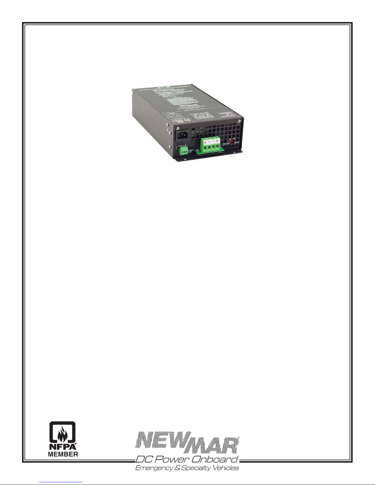
Emergency Vehicle Battery Charger
Model: EV-40
Installation/Operation Manual
Table of Contents
Section Topic Page
QUICK REFERENCE DRAWING………………………………….........….....……......………….......... 2
I) GENERAL INFORMATION…................…..........….………….........…………...............…………… 3
II) IMPORTANT SAFETY INFORMATION…....…......................…………….........………………… 3
III) INSTALLATION……………………………………………………………………................….…....... 4
A) Materials Provided…………………………………………….….............................… 4
B) Location……………………………………………………..................……….......…… 4
C) Mounting………………………………………………………............………..………… 5
D) DC Output Wiring, Battery & Auxiliary Loads…………..…….......................... 5
E) AC Input Wiring............................................................................................................. 7
IV) OPERATION…………………………………………………………………………............................. 7
A) Three Stage Charge Regimen…………………………........................................... 7
B) Time-Out Circuit…………………………………………………....................…............ 8
C) Gel-Cell/AGM/Lead-Acid Selector Switch…………..…................................…. 8
D) Remote Monitor Panel Option………………………………….……………….…… 8
E) Cooling Fan.................................................................................................................... 8
F) Power-On Indicators……………………………………………………………............. 9
V) APPLICATION NOTES………………………………………………..…………………………........ 9
A) Start Up…...……………………………………………..…………………....................... 9
B) Constant Versus Occasional Use……………..…………………………................. 9
C) Proper Load Sizing………………………………….…………………………............... 9
D) Operation with Engine…………………………....…………………………............... 10
E) Operation as a DC Power Supply (stand-alone DC power source)…….… 10
VI) SPECIFICATIONS…………………………………………………………………………………....... 10
VII) TROUBLESHOOTING………………………………………………………………........................... 11
VIII) BATTERY CARE TIPS…………………………………………………………................................ 13
UNIT DIMENSION DRAWING…………………………………………………………………….......... 14
P.O. Box 1306
Newport Beach
California 92663
www.newmarEVpower.com
M-EV40
As of April 2011
Phone: 714-751-0488
Fax: 714-957-1621
E-Mail: [email protected]
Page 2
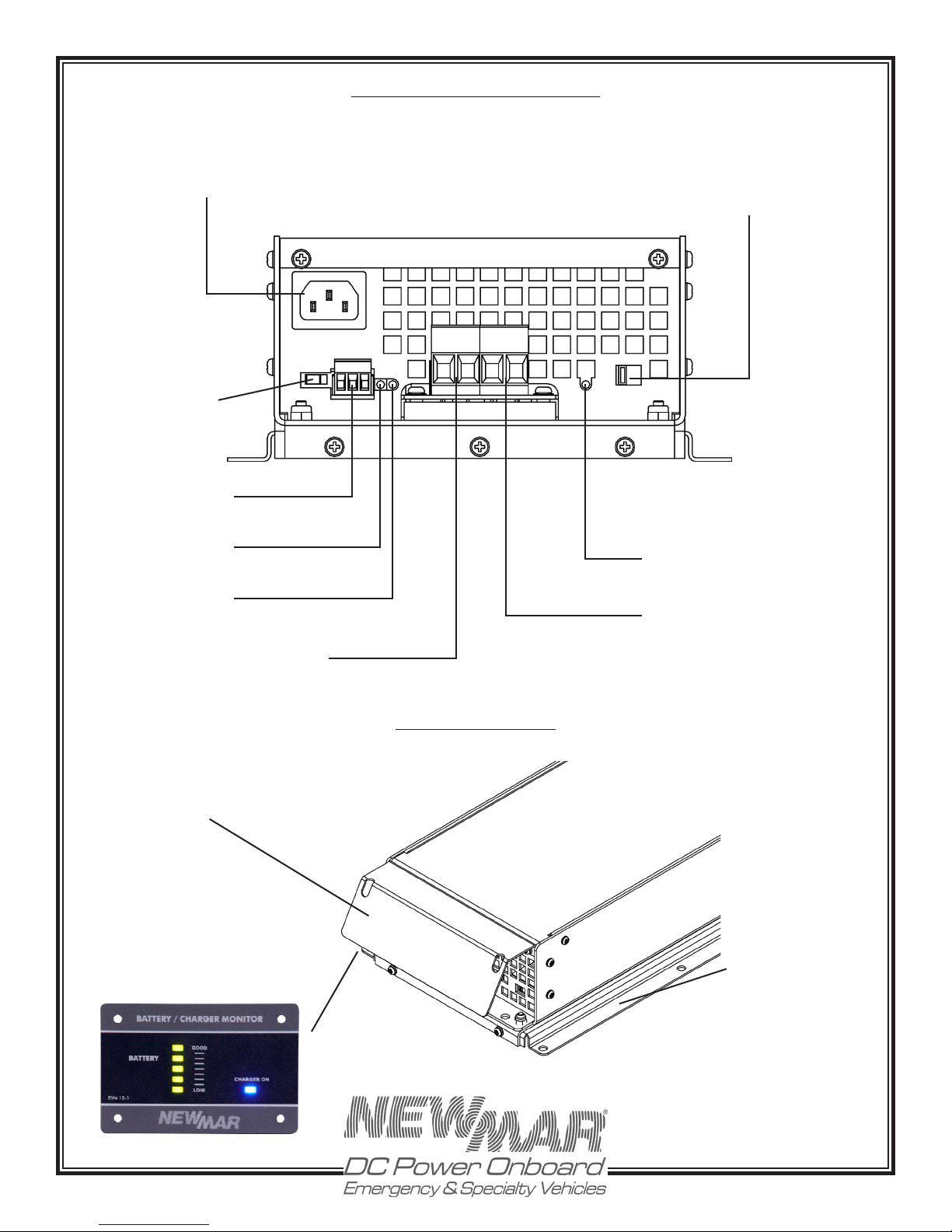
AC Plug Input Socket (IEC) Modular
Plug, Cord Provided; Pg. 7
Battery Type Selector
Switch (Gel-Cell/
Lead-Acid/AGM);
Pg. 8
Remote Meter Plug-in
Connector; Pg. 8
Quick Reference Drawing: EV-40
BATT AUX
+ - - +
Auxiliary Output Selector Switch:
A) powered only when AC shore
power connected (battery saver
mode), B) continuously connected to vehicle battery; Pg. 6
A - B
AC Power Indicator
Light (Green); Pg. 9
DC Output Inidcator
Light (Green); Pg. 9
Battery Output Connector Block - 40
Amps Maximum; Pg. 5
Protective Front Panel Kick Plate
(Optional); Pg. 5
Remote Meter, EVM-12-1
(Optional); Pg. 8
Auxiliary Output Indicator
Light OK (Green); Pg. 9
Auxiliary Output Connector Block
- 15 Amps Maximum (Air Pump,
Hand Lights, Radios); Pg. 5
Optional Accessories
Slide-in and Lock
Mounting Plate
(optional); Pg. 5
P.O. Box 1306
Newport Beach
California 92663
www.newmarEVpower.com
2
Phone: 714-751-0488
Fax: 714-957-1621
E-Mail: [email protected]
Page 3
1) General Information
The EV™ Series Battery Charger represents a new phase in
charger design and performance. It’s ideal for application
on emergency and specialty vehicles, utilizing “smart”
switching circuitry which puts batteries through the
optimum three-stage charge process, adapts for gel-cell,
AGM or lead-acid batteries, is rated for continuous duty
and is housed in an aluminum case with an optional
slide-in front access installation bracket.
7. Make sure the cord is located so that it will not be stepped
on, tripped over, or otherwise subjected to damage or stress.
8. An extension cord should not be used unless absolutely
necessary. Use of an improper cord could result in the risk
of fire and electric shock. If an extension cord must be
used, make sure:
A) That pins on the plug of the extension cord are the same
number, size and shape as those on the plug of the charger.
Following is a brief listing of some of the more important
features/options. Each is fully detailed later in this manual:
• Three step “smart” charging: bulk, absorption, oat
• Gel-Cell/AGM/Lead-Acid switch selects optimum charge/
oat voltages based on battery type
• 90-264VAC, 50-60 Hz input – can be used anywhere in
the world
• Current limited – prevents damage in case of overloading
• Thermally controlled cooling fan allows continuous
operation at full-rated output
• High charge voltage ti me - out circ u it prevent s
overcharging during continuous high amperage demand
• Optional Remote Panel allows remote monitoring of
charger status
• Use as a power supply without in-line battery; allows
continued use of DC powered electronics (when AC is
available) in the event that batteries must be taken offline or removed
• Auxiliary output for electronics, air compressors, and
hand lights
II) Important Safety Instructions
1. SAVE THESE INSTRUCTIONS – This manual contains
important safety and operating instructions for the EV-40
Battery Charger.
2. Before using this battery charger, read all instructions
and cautionary markings on (1) the battery charger, (2)
the battery, and (3) product powered by the battery.
3. CAUTION – To reduce the risk of injury, charge only 6
cell (12 volt models) gel-cell or lead-acid rechargeable
batteries. Other types of batteries may burst, causing
personal injury and damage.
4. Do not expose charger to rain or spray.
5. Use of an attachment not recommended or sold by
NEWMAR may result in a risk of fire, electric shock or
injury to persons.
B) That the extension cord is properly wired and in good
electrical condition.
C) That the wire size is large enough for the AC amperage
rating of the charger. Refer to the SPECIFICATIONS Section,
page 10, to determine the full load input current of your
charger, and then use the chart below to determine the
correct gauge wire for any extension cord used.
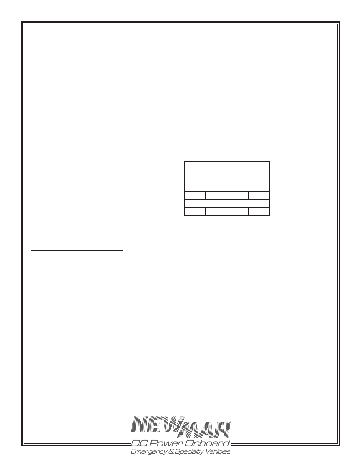
RECOMMENDED MINIMUM AWG
SIZE FOR EXTENSION CORDS FOR
EV BATTERY CHARGER
Length of Cord, Feet
25 50 100 150
Size of Cord, AWG
16 14 12 10
9. Do not operate the charger with a damaged cord or
plug; replace them immediately.
10. Do not operate the charger if it has received a sharp
blow, been dropped, or otherwise damaged; take to a
qualified serviceman.
11. Do not disassemble the charger; take it to a qualied
serviceman when service or repair is necessary. Incorrect
reassembly may result in a risk of electric shock and fire.
12. To reduce the risk of electric shock, disconnect
the charger from AC source before attempting any
maintenance or cleaning.
WARNING – RISK OF EXPLOSIVE GASES
1. WORKING IN THE VICINITY OF A LEAD-ACID BATTERY
IS DA NGEROUS. BATTERIE S G ENE RATE EXPLO SIV E
GASES DURING NORMAL BATTERY OPERATION. FOR
THIS REASON, IT IS OF THE UTMOST IMPORTANCE THAT
BEFORE INSTALLING AND USING YOUR CHARGER, READ
THIS MANUAL AND FOLLOW THE INSTRUCTIONS EXACTLY.
6. To reduce the risk of damage to the electric plug and
cord (if plugged into an AC outlet), pull by plug rather
than cord when disconnecting the charger.
P.O. Box 1306
Newport Beach
California 92663
www.newmarEVpower.com
3
Phone: 714-751-0488
Fax: 714-957-1621
E-Mail: [email protected]
Page 4

2. To reduce the risk of battery explosion, follow these
in structions and thos e publ ished by the b attery
manufacturer and by the manufacturer of any equipment
you intend to use in the vicinity of the battery. Review
cautionary markings on these products and on the engine.
recharging instructions.
4. Study all battery manufacturers’ specific precautions
such as removing or not removing cell caps while charging
and recommended rates of charge.
PERSONAL PRECAUTIONS
1. Someone should be within range of your voice or close
enough to come to your aid when you work near a leadacid battery.
2. Have plenty of fresh water and soap nearby in case
battery acid contacts skin, clothing, or eyes.
3. Wear complete eye and clothing protection. Avoid
touching your eyes while working near a battery.
4. If battery acid contacts skin or clothing, wash
immediately with soap and water. If battery acid enters the
eye, immediately ood eye with running cold water for at
least 10 minutes and get medical attention immediately.
5. NEVER smoke or allow a spark or ame in the vicinity
of the battery or engine.
6. Be extra cautious to reduce the risk of dropping a metal
tool onto the battery. It might spark or short-circuit the
battery or other electrical part and cause an explosion.
7. Remove personal metal items such as rings, bracelets,
necklaces, and watches when working with a lead-acid
battery. A lead-acid battery can produce a short-circuit
high enough to weld a ring or the like metal, causing a
severe burn.
8. Use the battery charger for charging gel-cell or ooded
lead-acid batteries only. It is not intended to supply power
to a low voltage electrical system other than in a startermotor application. Do not use the charger for charging
dry-cell batteries that are commonly used with home
applications. These batteries may burst and cause injury
to persons and damage to property.
GROUND AND AC POWER CORD CONNECTION
1. The charger should be grounded to reduce risk of
electrical shock.
2. The Charger is provided with IEC certified AC power cord.
If, for any reason, the plug on the cord must be changed or
replaced, observe color coding of the AC wiring as follows:
Black………..................................…AC Hot (fused)
White………….................................AC Neutral
Green……...................…......………AC Ground (safety/earth)
The charger must be plugged or hard wired into an outlet
that is properly installed and grounded in accordance
with all local codes and ordinances.
DANGER: Never alter the AC cord or plug provided, unless
it is absolutely necessary for use with the AC outlet which
conforms to all relevant electrical codes. Any modification
of the cord must only be done by a qualified electrician.
Improper cord/outlet connection can result in a risk of
electrical shock.
EXTERNAL CONNECTIONS TO THE CHARGER SHALL
COMPLY WITH UL RECOMMENDATIONS, NEC, or NFPA
STANDARDS
III) INSTALLATION
A) Materials Provided
The charger is provided completely assembled and ready
for installation. Because of numerous installation variables,
the installer will need to provide four suitable ¼” mounting
screws/washers, as well as DC output wiring and battery
connectors. Proper sizes and gauges for the wire and
connectors are noted in Section III-D following.
9. NEVER charge a frozen battery.
PREPARING TO CHARGE
1. Be sure the area around the battery is well ventilated.
2. Clean battery terminals. Be careful to keep corrosion
from coming in contact with eyes.
3. Add distilled water in each cell until battery acid
reaches level specified by battery manufacturer. This
helps purge excessive gas from cells. Do not overfill. For a
battery without cell caps, carefully follow manufacturer’s
P.O. Box 1306
Newport Beach
California 92663
B) Location
The charger should be mounted on a wall, vehicle oor,
ventilated compartment or other suitable surface as close
to the batteries to be charged as possible. Do not mount
the charger directly over the batteries as fumes may cause
excessive corrosion. The area should be well ventilated
and free from excessive moisture, exhaust manifolds, and
battery fumes.
For maximum performance, the charger should not be
located in an area of extreme high temperature.
www.newmarEVpower.com
4
Phone: 714-751-0488
Fax: 714-957-1621
E-Mail: [email protected]
Page 5
IMPORTANT: Although the charger is constructed of
materials and in a manner which make it highly resistive
to the corrosive effects of moisture in the environment, the
charger is not waterproof. Do not mount the charger where
there is a possibility of water entering the unit. Evidence
of water entry into the charger will void the warranty.
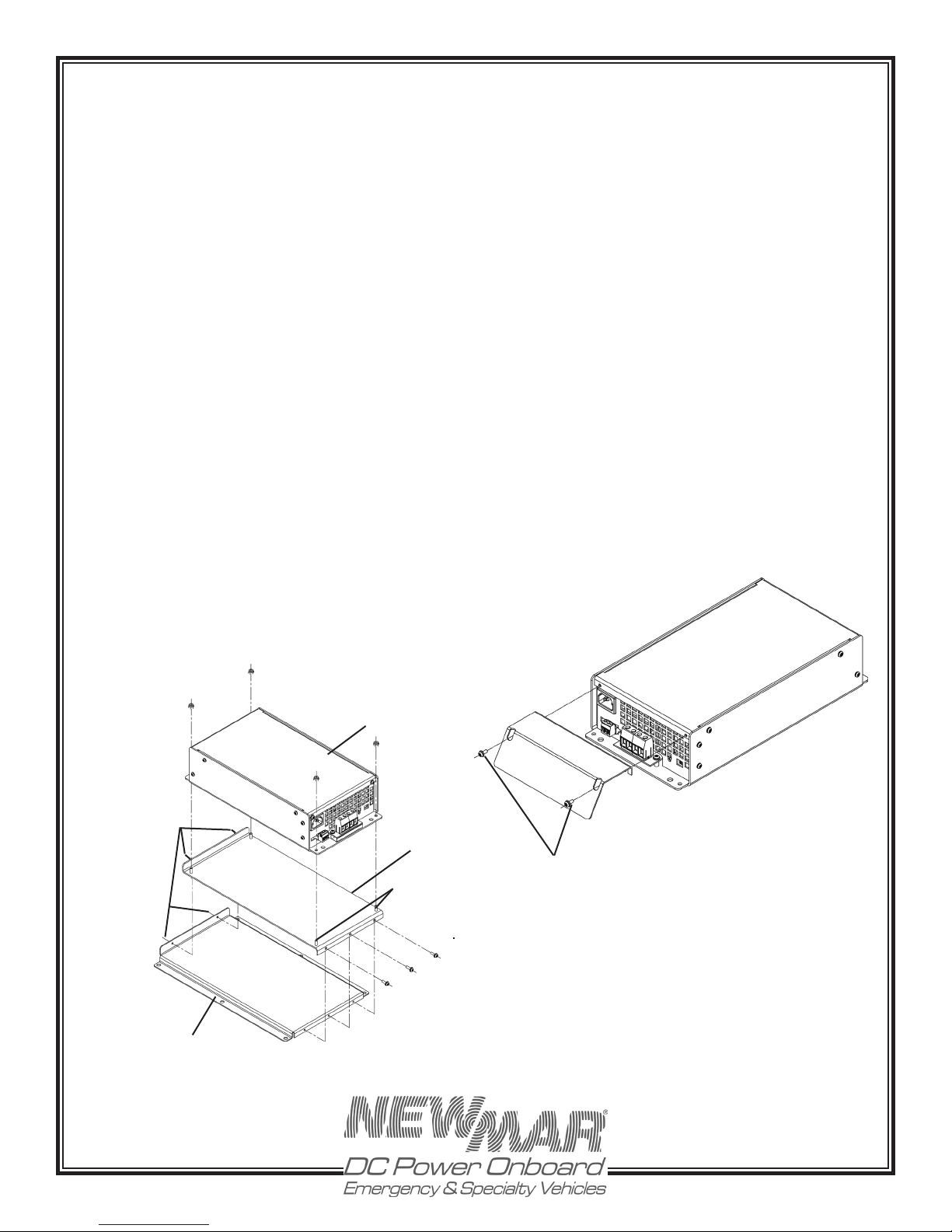
Slide-in and Lock Mounting System Description
The Slide-in and Lock mounting plate system is designed
to ease installation and removal of the EV-40 charger in
hard to access areas such as under seats and in small
compartments:
C) Mounting
Charger only (not using optional Slide-in Bracket
Assembly.)
The charger may be mounted on either a metal or nonmetal surface. You will require four (4) screws (wood or
machine screws, depending on mounting surface) with
washers, sized for ¼” holes, located on the tab end panel.
For extreme vibration installations, use optional High-Vibe
Mounting Kit (model Kit-L).
Optional Slide-In Bracket
For installation in hard to access locations such as under
a seat or in storage compartments, an optional “slide-in”
bracket assembly is available (P/N: 444-52790-0), which
permits total front access only removal and re-installation.
The system consists of a base mounting plate which is
secured to the vehicle, and a slide plate which attaches
to the bottom plate of the battery charger. This slide plate
has pins that slide in and engage with the base mounting
and are secured in place by front panel screws. The slide-in
plate can be oriented to the rear of the assembly or facing
out, at installers discretion. Reference Figure 2.
Figure 2: Optional Slide-In Bracket
• Charger is secured to the slide-in and lock plate
via 4 stud mounts.
Note charger can be oriented either direction
on the plate to meet desired location of front
panel wiring.
• The Vehicle mounting bracket is secured in its
desired location via 6 fasteners.
• Charger with plate attached the slides on to the
vehicle mounting bracket and is captured via
two insertion pins at one end and secured in
place via stainless steel fasteners and compression
angle bracket at other end.
Kick Plate
To protect wiring on the charger end panel, an optional
Kick Plate is available, (P/N: 444-5280-0)
It installs using the front end panel screws. Loosen the two
(2) screws shown in Figure 3, and attach the kick plate to
the battery charger case. Re-tighten screws.
Figure 3: Kick Plate
Insertion Pins To
Retain Charger To
Vehicle Mounting
Bracket
Vehicle Mounting Bracket
EV-40 Charger
Slide-in and
Lock Plate
Studs Secure
Charger to
Plate
Plate Screws
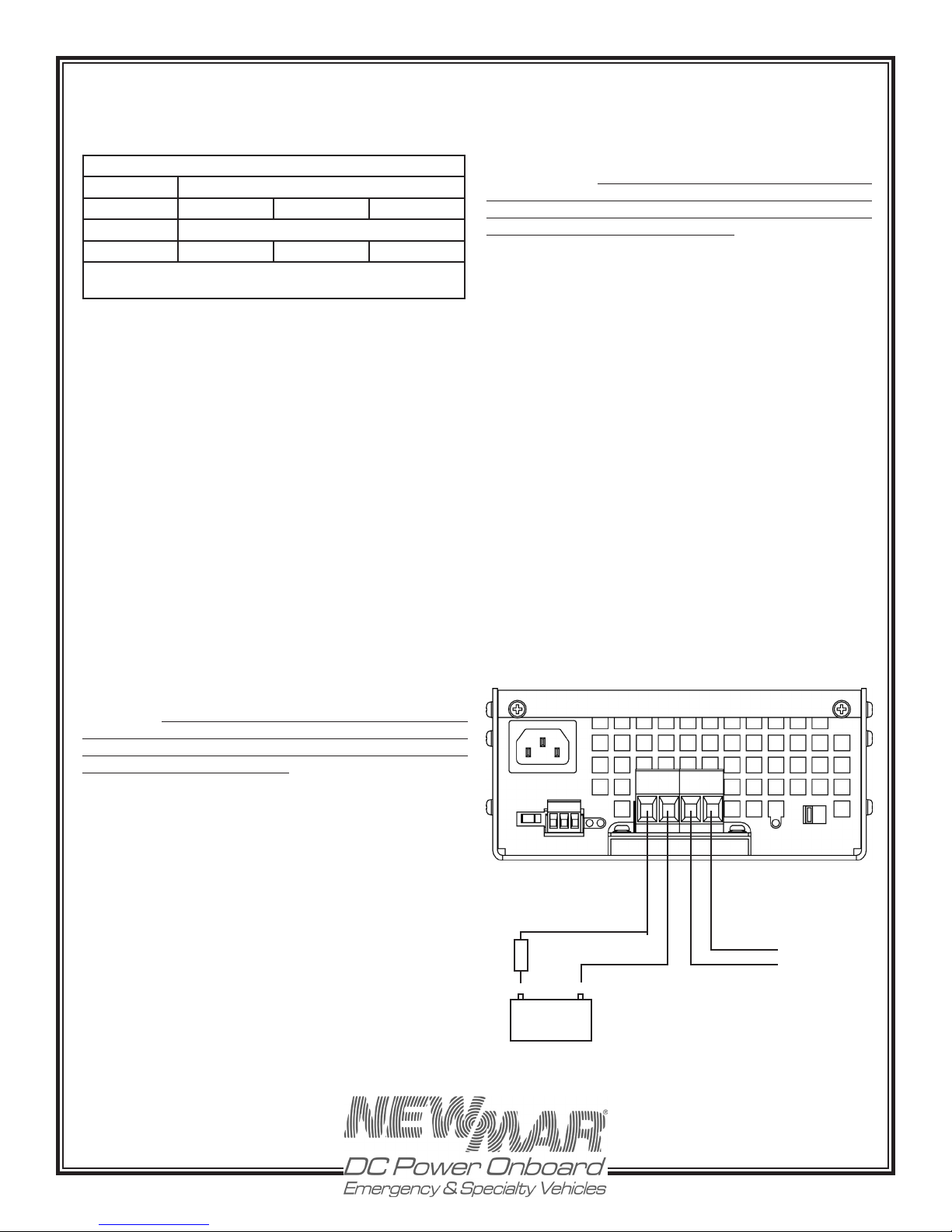
D) DC Output Wiring To Battery
Secure battery wiring to the output terminal block observing
proper polarity and wire gauge per the table on the
following page. Strip wires 1/2”, insert in barrel terminal
and secure in place by tightening the screw. Note, wire
terminals are not necessary. See Figure 4.
5
P.O. Box 1306
Newport Beach
California 92663
www.newmarEVpower.com
Phone: 714-751-0488
Fax: 714-957-1621
E-Mail: [email protected]
Page 6
The DC wire size table below may be used to determine
the correct gauge wire, based the length of the wire run
from the charger to the batteries.
DC Wire Size Table
Model
EV-40 #8 (10mm) #8 (10mm) #6 (16mm)
*Based on 10% voltage drop table and NEC minimum
Distance from Batteries, Feet
10 15 20
Wire Gauge AWG (mm)
wire size charge
Note: If batteries are closer to charger than battery switch,
wire directly to battery posts.
It is recommended that DC wiring from the charger to the
batteries be as direct as possible. Line voltage loss and
electronic noise interference of sensitive electronics are
possible if the charging leads are routed through a central
electrical distribution panel.
ENSURE THAT LEADS ARE PROPERLY FUSED AT THE
BATTERY.
Ensure that your connections are tight and that correct
polarity is carefully observed at all times. The battery posts
should be free of any rust or corrosion.
IM P ORTANT NOT E: EVEN MO MENTARY REVERSE
POLARITY CONNECTION MAY SEVERLY DAMAGE YOUR
CHARGER. THE POSITIVE (+) TERMINAL MUST BE WIRED TO
THE POSITIVE POST OF THE BATTERY AND THE NEGATIVE
OR COMMON (-) TEMINAL TO THE NEGATIVE POST OF
THE BATTERY OR COMMON BUS.
If the battery was connected to the charger backwards, the
fuse should blow to protect DC wiring, however; damage
to internal components may also have occurred. If the
replacement fuse blows, return the charger to an electronics
service professional or to the factory for a thorough
inspection. Note: The internal fuses do not provide protection
if there is a short in the wiring between the charger and the
battery. The battery is itself a power source and charging
leads should be fused at the battery.
Auxiliary Output
As shown in Figure 4, there are two terminals on the output
connection block labeled auxiliary +/-. This output is
intended for auxiliary loads such as air pumps, electronics,
and hand lights, and is rated at 15 amps. Installer has the
option, via a front panel selector switch, of powering the
auxiliary output only when the AC is applied to the charger
(switch position A), thus never discharging the battery
directly, or alternatively, allowing the auxiliary circuit to be
powered all the time from the vehicle battery, regardless
of whether the charger is operating or not (switch position
B). Note that in position “B”, if the charger is not operating
for an extended period of time or the engine alternator
not running, the auxiliary loads will eventually drain the
vehicle battery.
The auxiliary output circuit is protected by an auto-resetting
circuit breaker, so if the auxiliary loads exceeds 15 amps,
the breaker will cycle on and off. A front panel LED is
wired to this breaker and will extinguish when power is
not available at the aux circuit terminals.
Figure 4: DC Output Wiring
CAUTION: Do not attempt to increase battery bank
capacity by splitting the output of one of the banks with
a diode-type battery isolator. Undercharging may occur
on the output bank, as a result. If you wish to add another
isolated battery bank, use of NEWMAR’s Battery Integrator
is recommended. Contact the factory for details.
An important Note about the DC Output Fuse(s): internal
DC wiring is protected by the internal DC output fuse(s). The
current limiting circuit of the charger should prevent these
fuses from blowing under normal operating conditions. If
the DC fuse(s) blow, this may indicate a reverse polarity
hook-up or an internal short.
Always disconnect AC to the charger before checking
fuses. To check or replace the DC fuse, the cover must be
removed. To do this requires removal of two screws from the
front of the unit and five screws on each side. The DC fuse
is mounted on the main circuit board. Be sure to replace
with the same type and value as indicated on the fuse.
BATT AUX
- ++ -
Fuse
+ -
12 Volt
Battery
Note: Output Fuse Size Recommended
125-150% of Cable Ampacity.
A - B
+
-
Auxiliary Loads:
15 Amps Max
• Air Pump
• Hand Lights
• Electronics
6
P.O. Box 1306
Newport Beach
California 92663
www.newmarEVpower.com
Phone: 714-751-0488
Fax: 714-957-1621
E-Mail: [email protected]
Page 7
E) AC Input Wiring
An IEC certified 3 foot AC cord is provided that plugs into
the charger and a proper outlet. If the plug is not suited to
the available outlet, 1) obtain an IEC cord with appropriate
plug or 2) obtain the correct plug for the outlet and install
it on the provided IEC cord. When installing the plug, pay
careful attention to the pin wiring as follows:
Black……………….……………………….……AC Hot (fused)
white………………………………………………...AC Neutral
Green ……………….........……….…AC Ground (safety/earth)
The charger will operate on 90-264 VAC input-No selectors
with setting required
A power cord cable clamp has been provided to prevent
accidental disconnect of the AC cord. After the plug has
been inserted into the charger, snap the pre-formed clamp
around the AC input cable as close to the insertion point
as practicable and use a screw to fasten the clamp tightly
to the surface on which the charger is mounted..
Hard-wiring AC Input
If desired, the AC input to your charger may be hard-wired
directly to the AC distribution panel or junction box. Install
the charger end of the provided input cord as described
above, then cut off the plug and splice onto three conductor
marine-grade cable with crimp butt connectors, observing
color codes and fuse/circuit breaker ratings as above. Use
minimum 16 AWG cable.
time without loss of batteries’ electrolyte (gel or liquid) which
may be caused by sustained charging at higher voltages.
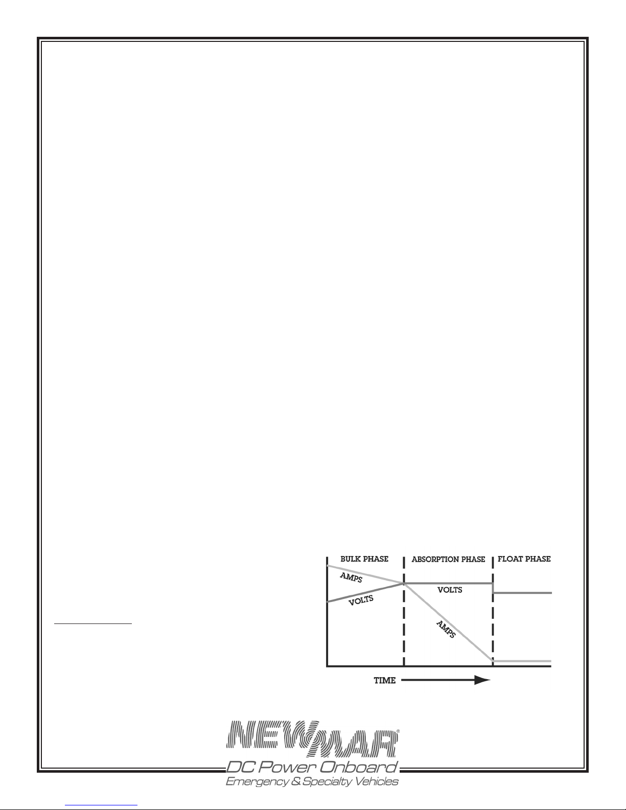
This three stage regimen is initiated each time AC is first
applied, when drained batteries are most likely to be
encountered.
1) Bulk Charge – When batteries are signicantly discharged
the charger responds initially by delivering a high amount
of DC current, at or near the charger’s maximum rated
output, in order to rapidly replenish them. It is during this
stage that charging current is maintained at a high level
as battery voltage increases. Bulk charging continues until
battery voltage reached the “charge” voltage level (where
batteries are at about 75-80% of capacity). A current limit
circuit prevents charger overload during this maximum
output stage
2) Absorption Charge – During this second stage of
the charge cycle, battery voltage is maintained at the
“charge” voltage level. Output current begins to taper off
as the battery plates become saturated. Charge voltage
is maintained until the current sensing circuit detects
that output current has tapered to about 5-15% of charger
rating*. At this point, the batteries are at about 95% of full
charge and the charger switches to the third and final
stage of the charge cycle.
*Note: The absorption phase may also be ended by the
time-out circuit. See Section B following for a complete
explanation of the purpose and functioning of the timeout circuit.
AC input for the charger must be plugged into an
appropriate, over-current protected three prong outlet
OR routed through a separate dedicated fuse or circuit
breaker on an AC distribution panel with proper safety/
earth chassis ground in accordance with all local codes
and ordinances.
CAUTION (230 VAC applications only): If AC input is
derived from a source consisting of two HOT leads
(phase-to-phase 230 VAC input voltage), an external fuse
or circuit breaker must be used to protect the unfused
(formerly NEUTRAL, now HOT) lead.
Input Fuse Replacement - The AC input of your charger
is protected by an internal input fuse. This indicates the
charger has an internal short, return the charger for service.
IV) OPERATION
A) Three Stage Charge Regimen
The Battery Charger features the three stage charge
regimen which is widely recommended by battery
manufacturers for allowing the fastest possible recharge
3) Float Charge – For extended battery life, the Phase
Three then automatically switches to a lower oat voltage
level. This oat charge keeps batteries at peak condition
without overcharging. The charger may be left in this
stage for months without attention (though periodic checks
of electrolyte level in ooded batteries is recommended.)
FIGURE 3: Typical Charger Output Graph (into battery
without load)
*
* Approximately 10 hours maximum
P.O. Box 1306
Newport Beach
California 92663
www.newmarEVpower.com
7
Phone: 714-751-0488
Fax: 714-957-1621
E-Mail: [email protected]
Page 8
B) Time-Out Circuit
Batteries have a tendency to lose their electrolyte and
may be damaged if they are maintained for long periods
of time in the elevated voltage of the absorption phase.
Therefore, the Phase Three Charger employs a special
time-out circuit. This circuit is initialized each time AC is
first applied to the charger (or when the re-initialize button
on the optional remote panel is activated) and runs for a
pre-set interval before forcing the charger to go into the
oat (lower voltage) mode. The functioning of the charger
during this interval is as follows:
If the current demand of the batteries/load falls below
5 AMPs to the circuit timing-out, the charger will
automatically switch to the oat mode. If demand rises to
about 8-10 AMPs, the charger will return to the elevated
output of the absorption phase. This switching back and
forth between modes may occur until the circuit times-out
(8-10 hours after AC is first applied), after which the charger
will remain at oat voltage, until the circuit is re-initialized,
either by turning the charger off and then on again.
Note: The Charger is able to deliver its full rated output
current while in float mode.
C) Gel-Cell/AGM/Lead Acid Battery Type Selector Switch
According to most battery manufacturers, the ideal
charging regimen for gel-cell, AGM, and wet or ooded
lead acid batteries differs somewhat.
The gelled electrolyte in a sealed battery may be lost
or damaged by high voltage and, once lost, cannot
be replaced as it can with a wet lead acid battery.
Manufacturers of gel-cells usually recommend an ideal
charge voltage which is slightly lower than a lead acid
battery.
However, when the charger is in the oat voltage mode
over lengthier periods of time, gelled electrolyte in a sealed
battery is not susceptible to evaporation, as is the nonimmobilized electrolyte of a wet lead acid battery, Thus
evaporation can be accelerated by the applied voltage.
Consequently, the ideal oat voltage is slightly higher for
a gel-cell than a lead acid battery.
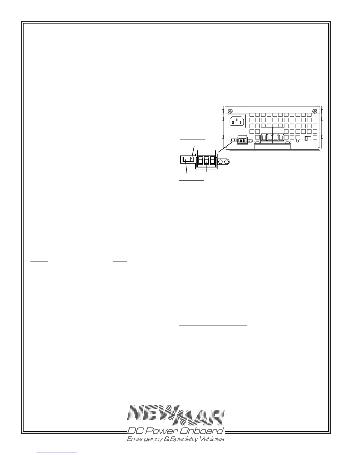
The ideal charge/oat regimen has been programmed
into the Charger for either sealed gel-cell or ooded lead
acid batteries. Simply make the proper selection for your
battery type via the slide switch on the left side of the front
panel. The switch positions are indicated on the front panel
(left Gel-Cell batteries, and right for Lead-Acid/AGM type
batteries). Use a ball point pen or small screwdriver to slide
it into the correct position. The charger is shipped from
the factory set for Lead-Acid/AGM batteries. Reference
Figure 5.
Note: A wide variety of batteries are available which do
not conform to conventional descriptions as “gel-cell” or
“lead-acid”. You are advised to consult the manufacturer
of your particular battery as to proper charging regimen,
and use the battery type selection switch setting which
most closely conforms to the recommended voltages.
See the SPECIFICATIONS Section, page 10, for the preset
charge and oat voltages.
Figure 5: Battery Type Selector Switch/Remote Panel
Connector
BATT AUX
- -
<
Lead-Acid/AGM
4 - 3 - 1
Gel-Cell
>
+ +
Remote Monitor Panel
Terminal Block
A - B
D) Remote Monitor Panel Option
A Remote Monitor Panel is available from NEWMAR
(EVM-12-1) which will enable you to monitor the battery
status at-a-glance from a remote location.
Model EVM-12-1 is a single battery bank charge status
indicator panel that is wired to the ‘remote panel’ terminal
block on lower left of the wiring panel. See Figure 5. A 3
wire connection is required for the meter, 22 AWG wire or
larger. The terminal block on the charger accepts a plug-in
connector that is provided in the parts bag with the unit.
The numbers ‘4-3-1’ printed on the top panel of the charger
coincide with the terminals on the remote monitor terminal
block on the charger front panel. See instructions provided
with the EVM panel for further installation details.
Remote digital meter option is also available - specify
NEWMAR model DCV. Connect + to terminal 1 and - to
terminal 3.
Remote Monitor TB Pin-outs
#1 - BATT (+)
#3 - BATT (-)
#4 - Charger-On
E) Cooling Fan
To maximize the life of the internal components and to allow
continuous operation at full rating, the Charger employs an
integral cooling fan. The fan draws air through the front of
the unit and expels it out the rear to improve cooling. The
fan operates whenever load and/or ambient temperature
P.O. Box 1306
Newport Beach
California 92663
www.newmarEVpower.com
8
Phone: 714-751-0488
Fax: 714-957-1621
E-Mail: [email protected]
Page 9
cause a rise in the internal heat sink temperature. Its
speed automatically increases/decreases in response to
load and/or ambient temperature increases/decreases.
Note: Under most circumstances, the fan will be in operation
when the charger is on.
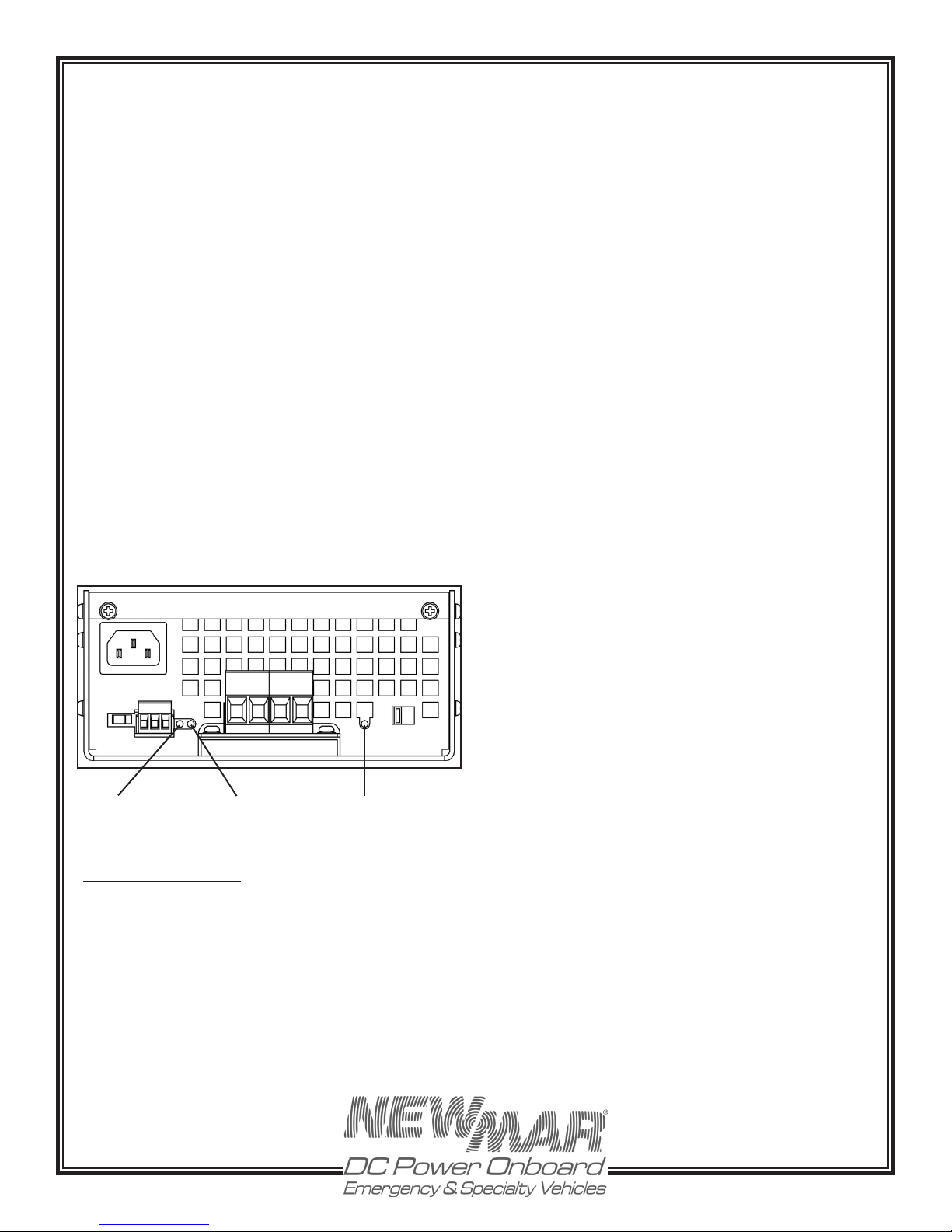
F) Indicator LED’s
There are three LED indicators on the front panel of the
EV-40 charger, reference Figure 6.
• AC OK - Green, indicates AC voltage is reaching the
charger, note this light will still illuminate if the unit’s
internal AC fuse has blown
load current exceeds 10-20% of the charger’s rated capacity,
the charger will go into the absorption mode and remain
there until current drops below 5-15% of capacity or until
the time-out circuit cycle is complete.
Note: The EV-40 charger is self-limiting and will rarely
blow an input fuse. If the input fuse should blow upon
first application of power, disconnect AC power to the
charger and consult the TROUBLESHOOTING Section VII
of this manual.
If the input fuse does need replacing, be sure to replace
it with the same type and value for continue protection.
B) Constant Versus Occasional Use
• DC OK - Green, indicates DC power being produced by
the charger
• AUX POWER OK - Green, indicates DC voltage applied to
Auxiliary output terminal block. If this light cycles on and
off, this indicates the circuit is over loaded and the internal
self resetting circuit breaker is cycling, in which case you
will need to reduce the load on the auxiliary circiuit.
See TROUBLESHOOTING Section VII, for additionals details
on the indicator light operation.
Figure 6: LED Indicators
BATT AUX
AC Power Indicator
Light (Green)
+ +- -
DC Output OK
(Green)
AUX Output Indicator
Light (Green)
A - B
V) Application Notes
A) Start Up
1) Before powering up your charger, check for tight electrical
connections to each battery in your system. Switch off any
DC loads on the batteries. Apply AC power.
2) Apply a load to the charger by switching on some lights, or
some other DC appliance. While current is demanded from
the battery system, the charger will automatically increase
its output in response to the increased load demand. When
In general, it is recommended that the charger be left
connected continuously to the AC distribution system
so that it will be in operation whenever AC is available.
This will maintain batteries at peak voltage and will
automatically compensate for the natural self-discharge of
the battery system. When a load is applied to the battery
system, the charger’s output will automatically increase to
supply the current which would otherwise draw battery
voltage down. Repeatedly allowing batteries to become
completely discharged before recharging will greatly
shorten their life. Leaving the charger on continuously
will prevent this.
While the output regulation of the charger will minimize
battery gassing and water loss, monthly checks of the
electrolyte level (for wet lead acid batteries) are still strongly
recommended. Some water loss is an inevitable aspect
of the charging process, and maintaining the correct
electrolyte level in your batteries is the most important you
can do to assure their maximum performance and long life.
C) Proper Load Sizing
The Charger is rated for continuous duty (e.g., the EV40 can deliver up to 40 amps continuously). While the
charger cannot be damaged by overloads that exceed
this continuous rating, excessive load demands may
draw battery voltage down faster than the charger can
resupply it. If the battery voltage continues to drop and
the output current is at maximum while the charger is
in service, check to see that your average DC loads are
not exceeding the charger’s rated output. If they are, you
may wish to consider adding another charger in parallel
to provide sufficient power for your requirements.
D) Operation with Engine
It is perfectly acceptable to allow the charger to remain
on when the engine is started and while it is running. The
current limit feature of the Charger will protect against
any damage due to the high current demands of the
engine cranking.
P.O. Box 1306
Newport Beach
California 92663
www.newmarEVpower.com
9
Phone: 714-751-0488
Fax: 714-957-1621
E-Mail: [email protected]
Page 10
As the alternator starts to charge the battery, the charger
output will decrease. When the battery voltage exceeds
the rated output voltage of the charger, no current will
ow from the charger as long as the batteries are in this
high state of charge.
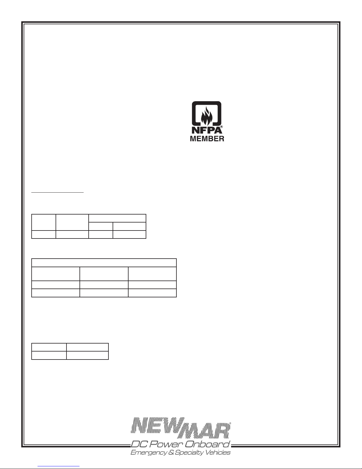
PROTECTIONFEATURES:
Input Fuse; Output fuse for reverse polarity protection;
Current limiting; Time and load controlled high rate
charge circuit; Ignition protected; IP 21
E) Operation as a DC Power Supply (stand alone DC
Power Source)
Most battery chargers are not suitable for powering
electronic devices directly, without a battery attached to
the output, as the high ripple and pulsing DC output (i.e.,
rectified AC output) can interfere with the operation of the
device. The EV charger is different. It employs a circuit that
produces an extremely well-filtered DC output. Therefore the
charger is able to power virtually any DC powered device
(within the unit’s rating) without the battery attached inline (if, for instance, the battery must be removed for any
purpose and AC is still available). All but the most sensitive
DC powered electronic devices will function as normally
as if powered by a battery. In addition, the current limiting
circuitry enables the charger to handle the high start-up
surges associated with inductive loads, such as DC motors.
VII) Specifications
INPUT RANGE (ALL MODELS): 90-264; 47-63 HZ (automatic)
Volts
Ouput
Amps (Cont
Model
EV-40 6.8/3.4 12 40
Input Amps
115/230V
Compliances:
Safety: EN60335-1
EMC: IEC 1000-4-2,
EN55014
OUTPUT VOLTAGES:
EV-40 Battery Charger
Setting Charge
@ 50% Load
Gel-Cell 14.0V DC 13.6V DC
Lead-Acid/AGM 14.2V DC 13.4V DC
Float @ .1 Amp
Load
Temperature Ratings: -20° C to + 60° C; Derate linearly
from 100% @ 50° C to 60% @ 60° C
INPUT/OUTPUT FUSE VALUES:
Model DC Output Fuse
EV-40 ATC-30 (2 each)
Case Size/Weight: 3.12” H x 6.8” W x 13.12” D; 7 Lbs.
7.92 x 17.27 x 33.32 (cm); 3.2 Kgs.
Mounting Dimensions: See page 13
P.O. Box 1306
Newport Beach
California 92663
www.newmarEVpower.com
10
Phone: 714-751-0488
Fax: 714-957-1621
E-Mail: [email protected]
Page 11
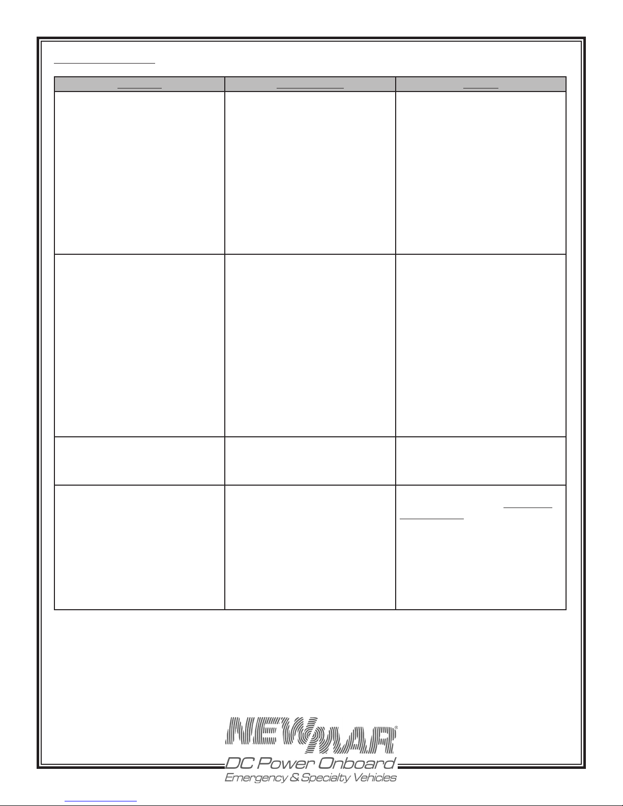
VII) Troubleshooting
Condition Possible Cause Solution
A) Batteries are not coming up to full
charge.
1) Extremely discharged batteries
requiring long recharge time.
2) Charger limiting its output due
to overload or over temperatu re
conditions.
3) Fan not operating properly causing
cha rger to protect again st overheating.
1) Turn off all D.C. loads and allow
charger 24- 48 hours to recharge
bat teries. See s e c t io n I V-B for
explanation of time-out circuit.
2) Reduce D.C. load and/or determine
cause of over temperature state
(See section III-B, “Location”).
3) Return for analysis/repair by
servicing dealer where charger
was purchased or contact NEWMAR
for a Return Materials Authorization
number.
B) Charger does not charge. No DC
“OK” light
C) Charger repeatedly blows
input fuse with no batteries
connected. AC “OK” light still on
D) Reverse polarity connection
At battery, green DC “OK” light
extinguishes.
1) Charger is not receiving AC input
voltage or is not receiving correct AC
1) Using a voltmeter, confirm, AC input
voltage, check input connections.
input voltage.
2) Refer to DC wiring installation
2) Charger output is not properly
connected to batteries.
3) Blown output fuse.
diagram for proper connections to
batteries.
3) Replace with another of correct
value (see section III-D, “DC Output
4) Defective charger.
Wiring”).
4) Return for analysis/repair by
servicing dealer where charger was
purchased or contact NEWMAR for
a Retu rn Materials Authorization
number.
Internal Short. Return for analysis/repair by servicing
dealer where charger was purchased
or contact NEWMAR for a Return
Materials Authorization number.
DC Output fuse and possibly
other components blown.
Disconnect AC power. Check for
proper battery polarity at charger
and at battery. After correcting miswires, replace the two blown fuses
with ATC-30 or ATO-30 automotive
blade style fuses. If fuses blow again
or DC “Ok” light extinguished or
ashing, return to servicing
dealer or contact NEWMAR for
Return Materials Authorization.
P.O. Box 1306
Newport Beach
California 92663
www.newmarEVpower.com
11
Phone: 714-751-0488
Fax: 714-957-1621
E-Mail: [email protected]
Page 12
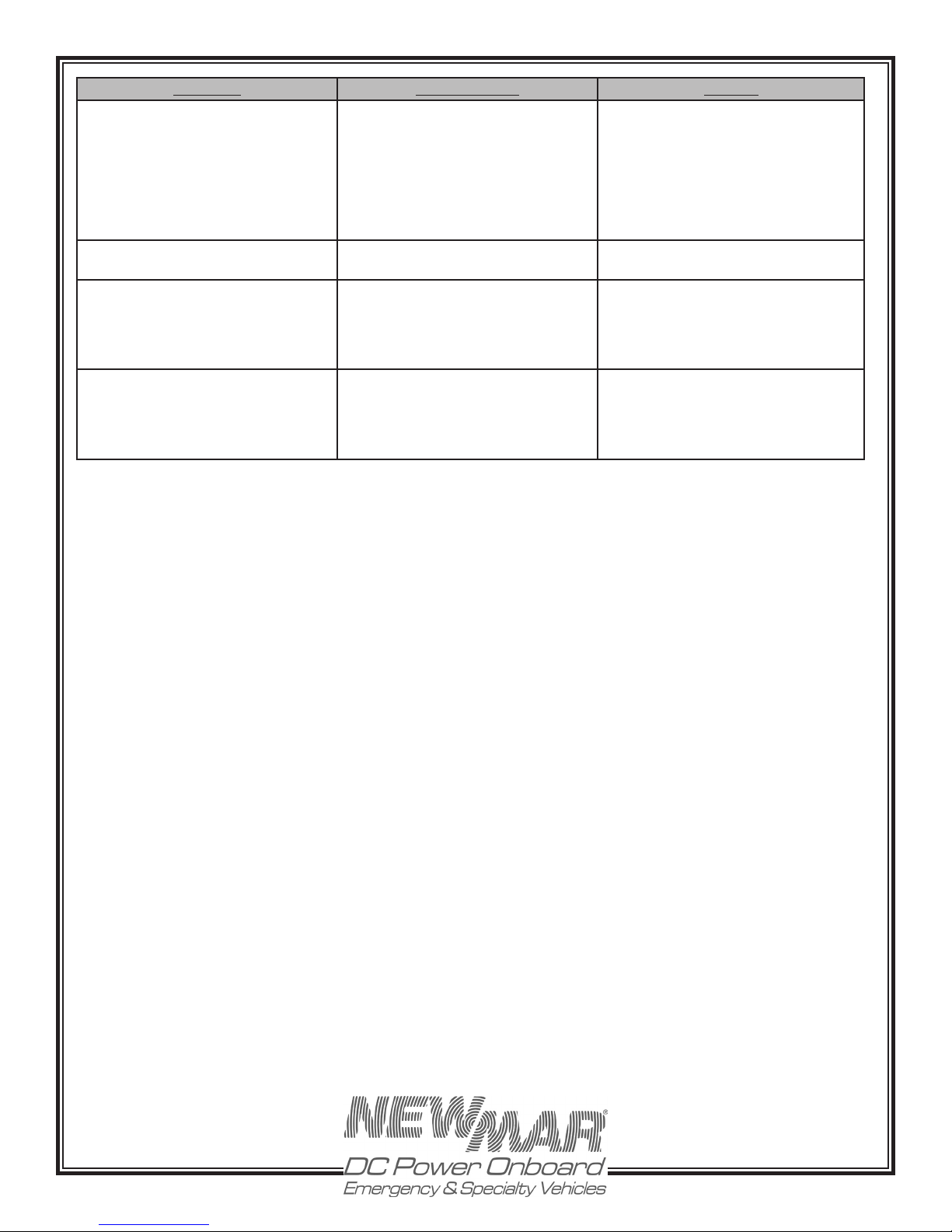
Condition Possible Cause Solution
E) EVM-12-1 meter does not work -
LED’s illuminate.
F) EVM-12-1 bar graph works but
“Charger On” LED does not
G) EVM-12-1 meter does not work
and the DC ”Ok” light is not on
1) Remove polarity to meter
2) Remote meter connector
terminals #3 & #1 shorted together
due to meter mis-wiring
3) Open circuit wire disconnected
Remote meter connector terminals #3
& #4 shorted together or open wire
Charger was damaged by
prolonged meter mis-wiring - see
section E-2 above.
1) Meter is protected from reverse
polarity. Correct wiring.
2) Immediately disconnect Remote
Meter connector from charger remove short and re-connect meter
(prolonged short circuit may damage
charger).
3) Check wiring for open connection.
Remove sho r t an d re - c o n nec t
EVM-12-1 meter
Return for analysis/repair by sevicing dealer where charger was
purchased or contact NEWMAR for
Return Authorization.
H) High output voltage
measured across charger
output terminals.
Batteries not connected to charger.
It is normal to read 1/2 volt higher
across any output bank when no
batteries are connected
Check for tight connection of
charging leads from charger to
batteries.
P.O. Box 1306
Newport Beach
California 92663
www.newmarEVpower.com
12
Phone: 714-751-0488
Fax: 714-957-1621
E-Mail: [email protected]
Page 13
VIII) BATTERY CARE TIPS
Regular maintenance and proper care will assure you
reliable service from the most depended upon and
sometimes most neglected items, your batteries and battery
charger. NEWMAR battery chargers are designed to keep
your batteries fully charged but your batteries also need
proper regular maintenance to provide a maximum life
of service.
The rate that water is lost by the battery is dependent on
several factors; battery condition, ambient temperature,
battery use, charge voltage, etc. It is normal for batteries
which are not maintenance-free to require topping off
about once a month.
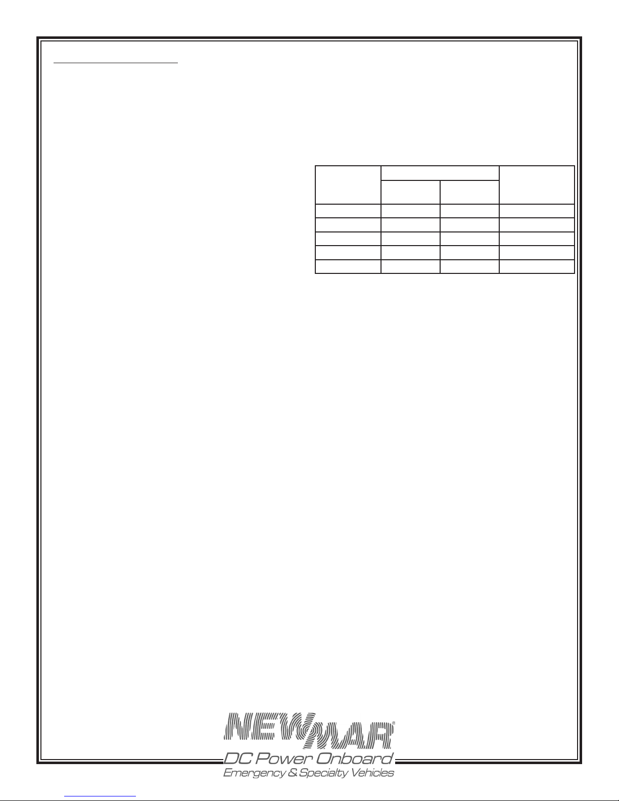
A battery’s state of charge may be monitored by checking
the specific gravity or by open circuit voltage. You may
use the following table to evaluate the condition of your
batteries:
A LWAY S R E A D A N D FO L LOW T H E B A T TE RY
MANUFACTURER’S INSTRUCTIONS
Battery Installation
Batteries must be securely mounted to prevent them from
falling over when the vehicle or boat is in motion. A
loose battery can do serious damage. Batteries should be
mounted in a battery box to contain any acid spill. Batteries
give off a certain amount of hydrogen gas when they are
charging. When concentrated, this gas is highly explosive.
Therefore make sure they are in an accessible place with
adequate ventilation for any hydrogen gas discharge.
Cleaning Batteries
Dirt and electrolyte salts can build up on the top of your
batteries. This accumulation conducts electricity stored in
the battery and can cause the battery to discharge by
itself. Therefore, at least twice a year, it is a good idea to
disconnect the battery cables and scrub the battery with
a baking soda solution. Rinse with fresh water and dry
with a clean cloth.
You may wish to purchase a set of terminal post corrosion
prevention rings. These are alkali-saturated felt rings that
slip over the battery post to reduce corrosion. Do not apply
grease to any part of the battery terminals, but you may
use an occasional light spray of silicone lubricant.
Routine Checks and Maintenance
Batteries should periodically be “exercised” (slowly
discharged and then recharged) to keep them in top
condition. New batteries may need to be exercised before
they will be capable of their full rating.
If your batteries are not the sealed type, distilled water
should be added to them whenever needed. The electrolyte
should cover the plates by about 1/2”, allowing a small air
space at the top. Do not fill the cells up to the filler cap as
this could cause the battery to sputter out electrolyte when
it is being charged. Only distilled water should be used
never plain tap water. Tap water contains chemicals and
elements that can alter the properties of the electrolyte,
including specific gravity. Some chemicals may also
create an insulating coating on the battery plates which
will retard current ow.
Specific Gravity
Measured by
Hydrometer
1.265 12.6 or more 25.2 or more Fully Charged
1.225 12.4 24.8 25% Discharged
1.190 12.2 24.4 50% Discharged
1.155 12.0 24.0 75% Discharged
1.120 11.7 or less 23.4 or less 100% Discharged
* Note: Wait at least 5 minutes after charging or discharging before
checking specific gravity or open circuit voltage. The battery’s
voltage needs to stabilize in order to get an accurate reading.
Open Circuit Voltage
12 Volt
System
24 Volt
System
State of
Discharge
@ 80° F
Troubleshooting Your Battery System
If your battery will not accept or hold a charge, one of the
following conditions may exist:
1. A BAD BATTERY. You may have a battery with an open
or shorted cell, a battery without any “life” left. Check by
charging the battery until all cells have a specific gravity
of 1.225 or greater at 80° F. If you are unable to obtain 1.225
in each cell, replace the battery. For maintenance-free or
gel-cell batteries consult the manufacturer.
2. A BAD BATTERY CHARGER. If the battery open circuit
voltage is low and/or the hydrometer indicates your
batteries are low, the battery charger should be providing
current to the batteries. If it is not, check AC input and check
to see that you have charging voltage on the output with
no battery attached. Note: You will not get an accurate
voltage reading on the output of the charger with no
batteries attached. This is checked merely to ensure that
you do not have an open circuit on the output.
The battery charger has a thermal cutout switch to turn
the charger off if it is overheating. If you suspect this is the
case, refer to the information regarding charger location in
the Installation section and cooling fans in the Application
Notes section.
3. ELECTRICAL LEAKAGE. You may have a previously
unsuspected source of current drain from the battery. To
check for a leakage of this sort, disconnect the battery
ground cable and connect an ammeter between the
negative battery post and ground If you have a reading
over .1 amp, there is a source of current drain from the
batteries which must be located and removed.
P.O. Box 1306
Newport Beach
California 92663
www.newmarEVpower.com
13
Phone: 714-751-0488
Fax: 714-957-1621
E-Mail: [email protected]
Page 14
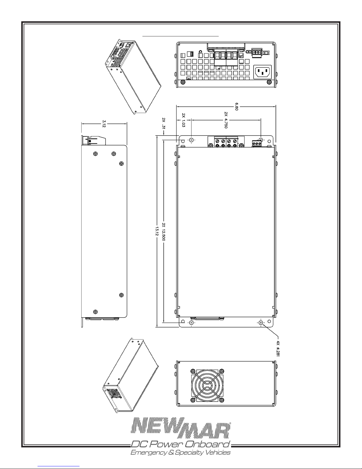
Unit Dimensional Drawing
P.O. Box 1306
Newport Beach
California 92663
www.newmarEVpower.com
14
Phone: 714-751-0488
Fax: 714-957-1621
E-Mail: [email protected]
 Loading...