


Owner’s Guide 2016
2017 VENTANA
OWNER’S GUIDE

2017 Ventana Owner's Guide Table of Contents
Chapter 1: Introduction
• A Letter from Our Family to Yours
• Introduction to Newgle
• Safety Notices in Newgle
• Warranty and Service
• About Your Owner's Information Package
• About the Delivery Process
Chapter 2: Safety
• Placards and Labels
• Before Driving Away
• Driving in Dangerous Conditions
• Seat Belt Safety
• Fire Safety
• Carbon Monoxide Safety
• LP Safety
Chapter 3: Care and Maintenance
• How to Wash and Dry Your Coach
• Waxing and Polishing Your Coach
• How to De-Winterize Your Coach
• How to Winterize Your Coach
• How to Care for and Maintain Your Dash
• How to Weigh Your Coach
• Routine Maintenance Schedule
Chapter 4: Appliances
• Cooktops and Ranges
• Dishwashers
• Fireplaces
• Microwaves and Convection Ovens
• Refrigerators, Freezers and Ice Makers
• Vacuums
• Washers and Dryers
Chapter 5: Chassis
• Axles
• Freightliner
• Fuel Systems
• Leveling Systems
• Steering Systems
• Wheels and Tires
Chapter 6: Electrical
• 12 Volt Electrical System
• 120 Volt Electrical System
• Batteries
© 2016 Copyright Newmar Corporation. All rights reserved. For the most up-to-date version of this content, and for more product-specific information, please refer to Newgle.

• Battery Basics
• Cord Reels
• Dash Electrical Systems
• Energy Management Systems
• Fuse Panels
• Generators
• Inverters and Converters
• Lighting
• Receptacles and Accessory Chargers
• Transfer Switches
Chapter 7: Electronics
• Camera and Video Monitoring Systems
• Chassis Monitoring Systems
• Navigation Systems
• Holding Tank Monitoring
• Lighting Controllers
• Security and Keyless Entry Systems
Chapter 8: Entertainment Systems
• Antennas, Cable, and Satellite Systems
• Blu-ray Players
• Dash Receivers, CD Players, and Stereos
• DVD Players
• Infrared Receivers, Remotes, and Switchers
• Speakers & Amplifiers
• Stereo Receivers and Home Theater Systems
• Televisions and Television Lifts
Chapter 9: Exterior
• Air Horns
• Awnings
• Compartments
• Entrance Doors, Handles, and Chimes
• Entrance Steps
• Exterior Lights
• Hitches and Towing Components
• Ladders
• Mirrors
• Paint, Roof, and Siding
• Wheelchair Lifts
• Windows
• Windshields
• Wiper Systems
Chapter 10: HVAC
• Air Conditioning, Dash
• Air Conditioning, Roof
• Furnaces
© 2016 Copyright Newmar Corporation. All rights reserved. For the most up-to-date version of this content, and for more product-specific information, please refer to Newgle.

• Hydronic Heating
◦ Oasis Hydronic Heating
• Thermostats
• Ventilation
Chapter 11: Interior
• Beds and Mattresses
• Cabinetry and Woodwork
• Ceiling
• Countertops
• Fabrics and Interior Furnishings
• Flooring
• Furniture
• Interior Doors
• Shades and Window Coverings
• Walls
Chapter 12: Plumbing
• Bathroom Faucets and Fixtures
• Filters
• Fresh Water System
• Hose Reels
• Kitchen Faucets and Fixtures
• Power Washers, Sprayers, and Exterior Showers
• Toilets
• Sinks
• Tubs and Shower Enclosures
• Waste Water System
• Water Heaters
• Water Pumps
Chapter 13: Slideouts
• Electric Bedroom Slideouts
• Electric Flat Floor Slideouts
• Electric Full Wall Slideouts
◦ How to Manually Retract an Electric Full Wall Slideout
• Electric Kitchen Slideouts
• Electric Wardrobe Slideouts
© 2016 Copyright Newmar Corporation. All rights reserved. For the most up-to-date version of this content, and for more product-specific information, please refer to Newgle.

© 2016 Copyright Newmar Corporation. All rights reserved. For the most up-to-date version of this content, and for more product-specific information, please refer to Newgle.

Chapter 1: Introduction
A Letter from Our Family to Yours
Welcome to the exciting world of recreational vehicle traveling and the growing Newmar family!
Congratulations on your purchase of a Newmar product.
Your coach proudly carries the Newmar torch, as a new
generation of RV’ing begins. We share your excitement at
this moment, and with you look forward to the years and
miles of adventure the RV lifestyle offers you in your coach.
Whether camping at your favorite remote fishing hole or
tailgating at the big game with your friends, have fun in the
knowledge that Newmar is with you 24 hours a day, 7 days a
week.
The Newmar Legacy
Your new coach was built with care using today's technology and old world craftsmanship. At Newmar, we strive to build
vehicles that are safe, dependable, and comfortable. Born on Christian principles, and from the desire to build not the
most, but the best, the legacy associated with the name Newmar is one of family pride and quality. It is the culmination of
decades of RV design and building experience. We take humble pride in our history of innovation. We introduced the
industry to the first slideout rooms, and continued our tradition of innovation with the first flush floor slideout in a
motorized coach and the smooth, seamless fiberglass body. Your coach is at the forefront of current technology, built by
the skilled hands and quality conscious eyes of craftsmen.
At Newmar, we recognize that a craftsman’s final product is only as good as the materials they use, so we are selective
about what we put into our coaches. We start with a foundation forged in the strength of steel and aluminum. We fill it
with beautiful, durable hardwoods, and select name brand appliances and components, then build it on a chassis built to
stand the test of time. Then we finish our units with an artist’s gentle touch.
The Newmar Warranty
Your coach has been built to the highest standards we have ever set and attained. That’s why we back it with a
12-month limited warranty. A heritage of quality and dependability makes it easy for us to offer that kind of coverage.
Please read the Newmar Limited Warranty and all other component warranties that apply to the equipment installed on
your unit. The limited warranties issued by the chassis and component manufacturers require periodic service and
maintenance. The owner's failure to provide this service and/or maintenance may result in the loss of warranty coverage.
Be sure to file the appropriate registration card with the component manufacturer as described with the individual
instruction booklets to activate the warranties on the components within your Newmar coach.
Customer Support
Carefully read both the instructions in your Owner’s Guide, as well as the booklets supplied by the chassis and
component manufacturers for important operation, safety, and maintenance information. This Owner’s Guide should be
kept in your vehicle for quick reference. Take time to get acquainted with your unit and how it operates. Should you have
any questions, consult your dealer or the Newmar customer support team. In addition to the assistance you receive from
the customer support team, we are also excited to announce a new approach to customer service: Newgle.
Your coach owner's guide is printed directly from Newgle, Newmar's dynamic, multi-faceted knowledge center created
specifically for Newmar coach owners and certified technicians. Because content pertaining to your coach is constantly
evolving and changing, the only way we can provide you with access to the most up-to-date and relevant information is
by linking you directly to it! Much of our information comes directly from the manufacturer of the items that are specific to
your coach model and year, so we urge you to check out the site for any additional information that may not (currently) be
included in your owner's guide. For more information on Newgle, refer to the Newgle information page in this section of
your owner's guide.
Our customers are extremely important to us, and we will make every effort necessary to ensure your satisfaction.
Contact Newmar
• Phone: 800.731.8300
• Mail: P.O. Box 30 | Nappanee, Indiana 46550-0030
• Websites: www.newmarcorp.com and https://newgle.newmarcorp.com
© 2016 Copyright Newmar Corporation. All rights reserved. For the most up-to-date version of this content, and for more product-specific information, please refer to Newgle.

© 2016 Copyright Newmar Corporation. All rights reserved. For the most up-to-date version of this content, and for more product-specific information, please refer to Newgle.

Introduction to Newgle
Welcome to the wonderful world of Newgle! As a Newmar coach owner, Newgle provides you with access to content
pertaining to your specific model and year. Whether you are using the search bar or the drop down navigation featured
on every page, you have the ability to locate the information you need with the click of a button.
Newgle consists of 11 categories, dozens of sub-categories,
and thousands of item-specific links connecting you directly
to the manufacturer of the items in your coach! Content is
regularly added and is only available to current Newmar
owners and certified technicians. Feel free to browse and
explore our new mobile-friendly website from your tablet or
smartphone.
How Do I Access Newgle?
Visit Newgle at https://newgle.newmarcorp.com to register for an
account. Because you now own a Newmar coach, click the link
associated with an owner account, "Coach Owner - Newgle Access
Request." You will be asked to provide your coach information and some
basic contact information, allowing the Newgle Team to verify ownership
and set up an account just for you!
Once your account has been created, you will receive a verification
email, which will include your username and password, transporting you
to a one-of-a-kind world of knowledge. If you have any questions
regarding your login information, please contact your Newmar
Model Specialist.
How Do I Navigate the Site?
If you are searching for information on your television, for example, there are many ways to navigate the site to find what
you need.
Newgle it! Search
The Newgle it! logo is available in the upper left corner
of every page throughout the site. Click on the logo at any
time to return to the Home page. The Newgle it! search bar
is also available on every page, making it possible for you to
conveniently initiate a search anytime from anywhere within
the site. By using search terms, such as 'Sony Television,'
or by typing in the model number of your television, you can
visit the pages listed in the search results immediately.
Drop-Down Menu
Choosing a category from the drop-down navigation menu
along the top of the page will take you to the landing page
for that category. From here, you can drill down to the subcategory level, allowing you to view the contents of each
category.
© 2016 Copyright Newmar Corporation. All rights reserved. For the most up-to-date version of this content, and for more product-specific information, please refer to Newgle.

Category Blocks
What Type of Information Will I Find?
Categories
Each of the 11 categories includes a brief overview of the type of information you
will find within the category and the layers beneath it. The overview may include
dangers, warnings, cautions, and important notices to highlight particular
aspects of your coach that may require additional attention. Many categories
also include images of labels (some of which may be noted as examples
only) that may be posted throughout your coach or on your components.
Click on a sub-category topic below the information to view more detailed
information about a particular component within the Entertainment Systems
category.
Choosing a category block on the Home page will take you
to the landing page for that category. Just like the dropdown menu, you can drill down to the sub-category level,
allowing you to view the contents of each category.
Sub-Categories
Each sub-category includes basic information about the topic at hand, including the location, operation, and function of a
particular system within your coach.
Below the information is a list of "item home pages" based
on the items relevant to your coach year and model.
In most cases throughout the site, this list will sort the relevant items by the product manufacturer, such as "Whirlpool
Washers and Dryers" or "Kwikee Entrance Steps." In the case of the televisions, they are not only sorted by
manufacturer, such as "Sony" or "Vizio," but also by the size of the television.
Click on an Item Home Page link below the information to view the exact models that may be installed in your coach.
© 2016 Copyright Newmar Corporation. All rights reserved. For the most up-to-date version of this content, and for more product-specific information, please refer to Newgle.

Item Home Pages
Item Home Page Items
Once an Item Home Page is selected, you will be directed
to a list of the components that are available (standard or
optional) in your coach based on the model and year. Each
item will be titled "Manufacturer Model Number ::
Manufacturer and Item Description."
Click on the item model to view more information.
Once an item model is selected, you will have access to
details such as the product name and
manufacturer, Newmar and manufacturer part
numbers, Newmar warranty information, as well as a photo
from ComNet, Newmar's parts catalog (when available).
Under the Manufacturer Product-Specific section, you will
have access to associated links to the direct manufacturer
or supplier for the following information, when available:
• Operation, Installation, and Maintenance Manuals
• Care and Maintenance Guides
• Product Specifications
• Safety Information
• Troubleshooting Guides and Service Manuals
• Parts and Accessories Catalogs
• FAQ's
• Videos
• Warranty Registrations
What if I Can't Find What I'm Looking For?
Our dedicated, full-time Newgle staff is working to provide
you with access to more model-specific information directly
from the manufacturers as quickly as we can.
By leaving feedback and requests for specific information at the botton of any page, you have the opportunity to directly
impact how we prioritize our efforts!
All of the information in Newgle is believed to be accurate at the time of publication. However, it may be
necessary to make revisions, and Newmar reserves the right to make any such changes without notice or
obligation.
© 2016 Copyright Newmar Corporation. All rights reserved. For the most up-to-date version of this content, and for more product-specific information, please refer to Newgle.

Safety Notices in Newgle
Reference is made to the following terms throughout Newgle and the Owner's Guide: Danger, Warning, Caution,
Important, and Notice. These terms indicate important information that must be understood and followed.
DANGER indicates an imminently hazardous situation that, if not avoided, will result in death or serious injury.
Failure to observe a DANGER may also result in damage to the equipment or unit.
WARNING indicates a potentially hazardous situation that, if not avoided, could result in death or serious
injury. Failure to observe a WARNING may also result in damage to the equipment or unit.
CAUTION indicates a potentially hazardous situation that, if not avoided, may result in minor or moderate
injury. Failure to observe a CAUTION may also result in damage to the equipment or unit.
IMPORTANT notices are not related to personal injury, but provide additional information to make a step easier
or clearer.
NOTICE indicates information that is not necessary or required, but may prove to be helpful.
Warranty and Service
“Customers say they’re loyal to us because they trust us to stand behind our products – from support, parts and service to
paying our warranties. It feels good to own a coach that has all of that behind it.” The only warranty offered by Newmar
Corporation is set forth in the written limited warranty that applies to this vehicle. The Newmar Corporation Limited
Warranty was provided to you by your selling dealer prior to purchase.
Warranty service required needs to be completed during the term of the warranty. Service work scheduled or
performed after the expiration of the Newmar warranty will not be covered.
The limited warranties issued by the chassis and component manufacturers require periodic service and maintenance.
The owner’s failure to provide this service and/or maintenance may result in the loss of warranty coverage.
The owner should review the Newmar Corporation Limited Warranty and other manufacturers’ limited warranties on all
components applicable to this vehicle. To activate the warranties on the components within your Newmar recreational
vehicle, be sure to file the appropriate registration card with the component manufacturer.
© 2016 Copyright Newmar Corporation. All rights reserved. For the most up-to-date version of this content, and for more product-specific information, please refer to Newgle.

If, for any reason, you have a problem obtaining satisfactory and timely warranty service that may substantially impair
the use, value, or safety of your Newmar coach, please call Newmar Customer Service toll free at (800)731-8300.
Customer Relations
If you wish to schedule maintenance work, schedule service work, or order parts you should notify your local authorized
Newmar Service Center to set up an appointment. If you are unsure of the location of the closest authorized Service
Center, contact Newmar Customer Service. You may also write to:
Newmar Corporation | Warranty Department | P.O. Box 30 | Nappanee, IN 46550
About Your Owner's Information Package
Included in your Owner's Information package are valuable documents about your vehicle and its components and
systems. The Newmar Owner’s Guide does not cover every possible detail of the equipment, standard and/or optional,
installed on or in your vehicle. Consulting the booklets and instruction manuals in this package will help you safely
operate, maintain, and troubleshoot these items.
Read all of the information and understand the safety and operating instructions included in the Owner’s Information
Package. To assure full warranty coverage, it is essential that all maintenance instructions are followed.
Information Sheet
An information sheet is provided containing important information about your coach for your convenience. Listed on this
sheet is the following information:
• Your coach's Newmar Serial Number. This number is
needed whenever making an appointment for service or
ordering parts through your Newmar Dealer or Service
Center.
• Your coach's Vehicle Identification Number (VIN). The
VIN is the legal identification of the completed vehicle and is
used by the state for vehicle registration.
• Your coach's Year, Brand, Type, and Floorplan
• Manufacturer, Model, and Serial Number of factory
installed equipment.
The manufacturer, model, and serial number of the appliances and accessories installed at the factory in your
unit are listed on this label for convenience. It is important that the label remain in the coach for identification
purposes. Do not remove or relocate this label.
About the Delivery Process
Throughout the manufacturing process, your vehicle has been inspected by Newmar qualified technicians. However, our
final inspection at the factory is not to be the last one. The pre-delivery inspection and systems check your dealer
performs are the final inspections done to the unit prior to you receiving your new coach. Your dealer may assist you in
understanding the limited warranties and with completing all warranty forms for the various appliances and accessories
installed in your unit.
Customer Responsibilities
To assist you in avoiding problems with your vehicle, we recommend you do the following:
1. Read the warranty. Go over it thoroughly with your dealer.
© 2016 Copyright Newmar Corporation. All rights reserved. For the most up-to-date version of this content, and for more product-specific information, please refer to Newgle.

2. Inspect the vehicle. Do not accept delivery until you have gone through the coach with the dealer. Newmar has
provided a check list to be used during retail delivery. Check each item on the list, and make sure the dealer does
the same. Do not sign this checklist until you have done checked off each item.
The sales literature versus actual specifics to the vehicle’s measurements, weights, or quantities may vary.
3. Ask questions about anything that you do not understand concerning your recreational vehicle.
4. Responsible Use. Your vehicle is designed to be used for recreational or temporary living purposes. It is not
designed to be used as a full-time residence or for commercial use. Commercial use means using as a business
asset, such as a mobile office or using the vehicle for lease/rental purposes.
Dealer Responsibilities
1. A pre-delivery inspection and systems check: thoroughly inspecting the vehicle and the operation of the factory
installed components.
2. A customer walk-through to familiarize the customer with the vehicle, its systems and components, and their
operation.
3. Delivery of the Owner’s Information Package. This package contains the warranty cards and registrations for the
vehicle and factory- installed components that carry a separate warranty. The detailed operating and maintenance
instructions on these components are also included in this package.
4. Assisting the customer in completing the component registration forms, at the customer’s request. To avoid loss of
warranty coverage, the dealer should review the limited warranty provisions with the customer, stressing the importance
of filing warranty cards and registrations to the component manufacturers within the prescribed time limit.
5. Providing the customer with information regarding warranty and non-warranty work on the vehicle, as well as its
separately warranted components, whether the customer is in or out of the area.
© 2016 Copyright Newmar Corporation. All rights reserved. For the most up-to-date version of this content, and for more product-specific information, please refer to Newgle.

Chapter 2: Safety
If you believe that your vehicle has a significant defect which could cause a crash or could cause injury or
death, inform the National Highway Traffic Safety Administration (NHTSA) and Newmar Corporation
immediately.
To contact NHTSA, call, write, or visit them on the web.
Phone: Auto Safety Hotline (toll free) at 1-888-327-4236 (TTY #1-800-424-9153)
Write: NHTSA, 400 Seventh Street S.W., Washington, DC 20590
Website: http://www.safecar.gov.
For More Information
Refer to the product manufacturer's owner's manual and links to learn more about your coach's detectors, seat belts, and
fire extinguishers.
Placards and Labels
A variety of placards and
labels are located
throughout your coach.
These are installed to aid
in the operation of a
component, or to warn of
potential dangers while
operating a specific
appliance, accessory, or
system.
These will include
warnings regarding the
electrical system, propane
gas system, fueling the
coach, and so on. It is
important to read these
placards and warnings to
ensure the safety and
proper operation of the
item.
Examples of such labels are provided above; one of these labels is affixed to your unit on/adjacent to your propane tank.
Reading, understanding, and heeding all labels and placards is critical to the safe, efficient use of your coach.
Before Driving Away
Prior to driving your vehicle, be sure you have read your entire owner’s guide and that you understand your
vehicle’s equipment completely and safely. Read and understand all of the instructions and precautions in this
owner’s guide and the chassis manufacturer owner’s manual before operating your new coach.
© 2016 Copyright Newmar Corporation. All rights reserved. For the most up-to-date version of this content, and for more product-specific information, please refer to Newgle.

Listed below are some safety precautions that must be adhered to while your coach is in motion. These precautions, as
well as others that involve possible damage to equipment, are also listed in the appropriate areas in this manual.
There are various adjustments that need to be made prior to starting and moving the vehicle. Among them are the driver’s
seat, the tilt steering, and the exterior side view mirrors, as well as checking the rear view monitoring system. In addition,
the following procedures will aid in your driving safety and extend your equipment’s life.
• Windows, mirrors, and light lenses are to be clean and unobstructed.
• Tires should be checked for proper cold inflation pressure.
• Wheel lug nuts should be checked for proper tightness.
• Fluid levels, including engine oil, transmission fluid, coolant, power steering fluid, brake fluid, and windshield
washer solvent, should be checked and filled, if necessary.
• Disconnect the unit. Store the sewer and water supply hoses, as well as shoreline power cords.
• Secure all cargo in the storage compartments in the event of a sudden stop.
• Verify that the step has retracted prior to engine ignition.
Driving in Dangerous Conditions
The cruise control is not to be operated on icy roads, extremely wet roads, winding roads, heavy traffic, or in
any other traffic situation where a constant speed cannot be maintained.
While driving on slippery surfaces, use care when accelerating or decelerating. Skidding and loss of vehicle
control may be the result of abrupt changes in speed.
Driving through water deep enough to wet the brakes may affect the stopping distance or cause the vehicle to
pull to one side. If you have driven through deep water, check the brake operation in a safe area to be sure
they have not been affected.
Never operate a vehicle if a difference in braking efficiency is noticeable. Extreme terrain and adverse weather
may affect the handling and/or performance of your vehicle.
Seat Belt Safety
One of the most important safety features in your vehicle is the restraint system. Research has shown that seat belts
save lives. And they can reduce the seriousness of injuries in a collision. Some of the worst injuries happen when
people are thrown from the vehicle. Everyone in a motor vehicle needs to be buckled up at all times.
These brief operation instructions are for quick reference only. Any quick start instructions provided should
not take the place of the complete Operation Manual provided by this item's manufacturer.
© 2016 Copyright Newmar Corporation. All rights reserved. For the most up-to-date version of this content, and for more product-specific information, please refer to Newgle.

It is extremely dangerous to ride in a cargo area, inside or outside of a vehicle. In a collision, people riding in
these areas are more likely to be seriously injured or killed. Do not allow people to ride in any area of your
vehicle that is not equipped with seats and seat belts. Be sure everyone in your vehicle is in a seat and is
using a seat belt properly.
How to Operate Your Seat Belts and Restraint System
If you wear your safety belt improperly, both the effectiveness and comfort will decrease.
Operating Instructions for Lap/Shoulder Combination Restraints
1. Enter the vehicle and close the door. Sit back, and adjust the seat.
2.
The latch plate of the belt is above the back of your seat. Grasp the latch plate, and pull out the belt. Slide the
latch plate up the webbing as far as necessary to make the belt go around your lap.
3. When the belt is long enough to fit, insert the latch plate into the buckle until you hear a “click.”
4. Position the lap belt across your thigh, below your abdomen. If you need the lap portion tighter, pull up a bit on
the shoulder part. A snug belt reduces the risk of sliding under the belt in a collision. Position the shoulder belt on
your chest so that it is comfortable and not resting on your neck. The retractor will withdraw any slack in the belt.
5. To release the belt, push the release button on the buckle.
Some shoulder belts can be adjusted upward or downward to help position the belt away from your neck.
Push on the anchorage cover to release it, and then move it up or down to the position that serves you best.
Operating Instructions for Lap Belt Restraints without a Shoulder Harness
Always wear your seat belt when the vehicle is in operation.
1. Slide the latch up the webbing as far as necessary to make the belt go around your lap.
2. Insert the latch plate into the buckle until you hear a “click.”
Adjust and position the belt low and snug across your hips by removing the slack from the belt.
3.
To release the belt, push the release button on the buckle.
4.
Each belt is intended to restrain only one person at a time. Do not put two people under one belt.
Never attempt to restrain a child in your lap using the lap belt around both you and the child. The child could
be severely injured or killed in the event of a collision.
© 2016 Copyright Newmar Corporation. All rights reserved. For the most up-to-date version of this content, and for more product-specific information, please refer to Newgle.

Seat belts are matched sets. Do not mix or use this belt or parts of this belt with other types of seat belts.
Child Restraints
Everyone in your vehicle needs to be buckled up at all times. Every state in the United States and all Canadian
provinces require that small children ride in proper restraint systems. This is the law, and you can be
prosecuted for ignoring it.
There are different sizes and types of restraints for children from newborn to near-adult size children. Use the restraint
that is correct for your child:
• The restraint must be appropriate for your child's weight and height. Check the label on the restraint for this, too.
• Carefully follow the instructions that come with the restraint. If you install the restraint improperly, it may not work
when you need it.
• Buckle the child into the restraint exactly as the manufacturer's instructions have directed.
How to Maintain Your Seat Belts and Restraint System
Periodically examine your restraint equipment to be sure it functions correctly and to be sure there are no worn or broken
components that either needs repair or replacement. Damaged parts must be replaced immediately. Do not disassemble
or modify the system.
Restraint equipment must be replaced after an accident if they have been damaged. If there is any question regarding
belt or retractor condition, replace the belt. It is a good idea to have your restraint system inspected during each periodic
scheduled maintenance session.
A frayed or torn belt could rip apart in a collision and leave you with no protection. Inspect the belt system
periodically, checking for cuts, frays, or loose parts. Damaged parts must be replaced immediately. Do not
disassemble or modify the system. Seat belt assemblies must be replaced after an accident if they have been
damaged (bent retractor, torn webbing, etc.)
If the belts need cleaning, use a mild soap solution or lukewarm water. Do not remove the belts from the vehicle to wash
them.
Do not bleach, dye or clean the belts with chemical solvents or abrasive cleaners. This may severely weaken
the fabric. In a crash, they might not be able to provide adequate protection.
Fire Safety
If a fire occurs in the vehicle, evacuate the vehicle as quickly and as safely as possible. Consider the cause
and the severity of the fire and the risk involved before trying to extinguish it. If the fire is major or fuel fed,
move away from and stand clear of the vehicle and wait for emergency assistance to arrive.
© 2016 Copyright Newmar Corporation. All rights reserved. For the most up-to-date version of this content, and for more product-specific information, please refer to Newgle.

The possibility of fire exists in all areas of life, and the recreational lifestyle is
no exception. Recreational vehicles are complex machines made up of many
materials, some of which are flammable.
Like most hazards, the possibility of fire can be minimized, if not totally
eliminated by recognizing the danger and practicing common sense safety
and maintenance habits. For safety reasons, your unit is furnished with both
a fire extinguisher and a smoke alarm.
Fire Extinguishers
The fire extinguisher is rated for Class B (grease, gasoline, diesel fuel,
flammable liquids) and Class C (electrical) fires. These are the most common
types of fires in vehicles. Fire extinguishers are mechanical, pressurized
devices. Care must be exercised when they are handled.
The extinguisher should be inspected at least once a month. More frequent
inspections may be required if the extinguisher is exposed to the weather or
to possible tampering. Do not test the extinguisher by partially discharging,
as it will cause a loss of pressure. Your fire extinguisher must be maintained
as the operator’s manual instructs for proper and safe operation.
Read the operator’s manual and the instructions on the fire extinguisher. Be
sure to know how and when to use the extinguisher and where it is located.
Failure to comply could result in an increased risk of fire, explosion, asphyxiation, serious injury, or death.
Smoke Detectors
The smoke detector installed in your coach is operated on a 9 volt
battery. The smoke detector is mounted on the ceiling in the living
area of the unit. Read the operating instructions for details on the
testing and care for this important safety device.
Test the smoke detector after the unit has been in storage, before
each trip, and at least once a week during use. Check your smoke
detector for the manufacturer’s expiration date. The battery needs
to be tested periodically and replaced once a year and/or when the
low battery signal sounds.
When cleaning the case on any of the detectors, use a damp cloth
or paper towel. Do not spray cleaners or wax directly into the case
as it may cause false alarms.
The detector should never be disabled because of nuisance or false alarm from cooking smoke or a dusty
furnace. Ventilate the unit with fresh air and the alarm will shut off. Never disconnect or remove the battery
from the smoke alarm.
© 2016 Copyright Newmar Corporation. All rights reserved. For the most up-to-date version of this content, and for more product-specific information, please refer to Newgle.

Carbon Monoxide Safety
Carbon monoxide is a colorless, tasteless, odorless gas. It is a by-product of the burning of fossil fuels (gasoline, propane
gas, diesel fuel, etc.). The chassis and generator engines, furnaces, water heater, propane gas refrigerator, and range
produce carbon monoxide constantly while they are operating.
Carbon monoxide is deadly. Read and understand the following precautions, as well as any warning labels in
your coach, to protect yourself and others from the effects of carbon monoxide poisoning.
If you, or anyone
else, experience
any of the following
carbon monoxide
poisoning
symptoms, exit the
coach immediately.
Seek medical
attention if the
symptoms persist.
Shut down the
coach and do not
operate it until it has
been thoroughly
inspected and
repaired.
• Dizziness
• Nausea
• Vomiting
Do not block the tailpipes or exhaust ports. Do not situate the vehicle in a place where the exhaust gases have
any possibility of accumulating either outside, underneath, or inside your vehicle or any nearby vehicles.
Outside air movements can carry exhaust gases inside the vehicle through windows or other openings remote
from the exhaust outlet. Operate engines, carbon monoxide-producing systems, or components only when
safe dispersion of exhaust gases can be assured. Monitor outside conditions to be sure that exhaust
continues to be dispersed safely.
Carbon Monoxide (CO) Detectors
The detector is equipped with a “sensor activation strip,” which must be removed for the detector to operate properly. This
should have been done during the dealer’s Pre-Delivery Inspection. Please check the detector to verify that the activation
strip has been removed. Please consult your carbon monoxide detector Owner's Manual for more detailed information.
The CO detectors are self-contained and do not require any maintenance other than normal cleaning and dusting.
• Muscular twitching
• Throbbing in the temples
• Inability to think coherently
• Weakness and/or sleepiness
• Intense headaches
Under no circumstance should you operate any engine while sleeping. When you are sleeping, you are not
able to monitor outside conditions to assure that engine exhaust does not enter into the coach. Check the
exhaust system frequently for damage. If damage is found, do not operate the system. Never modify the
exhaust system(s) in any way.
© 2016 Copyright Newmar Corporation. All rights reserved. For the most up-to-date version of this content, and for more product-specific information, please refer to Newgle.

LP Safety
Propane gas is extremely flammable. The propane detector in your coach is located in the main living area close to the
floor. It is wired to the 12 volt electrical system in your unit.
Read and understand the following precautions, as well as any warning labels in your coach, to protect
yourself and others from the risks of operating an LP system.
Your coach may be equipped with an ASME (American Society of Mechanical Engineers) approved propane tank. This
tank is controlled with an automatic pressure regulator. The propane tank contains liquid petroleum gas under high
pressure. As the fuel is used, the liquid gas vaporizes and passes through the tank valve to a regulator that
automatically reduces the pressure. The low-pressure gas is then distributed to the appliances throughout the pipe
manifold system.
The primary gas supply manifold is a black steel pipe running the length of the unit. Most secondary lines
leading to the gas appliances are made of copper tubing with flare fittings. If any of these lines rupture, do not
attempt to splice them. Always run a new line. Gas distribution work must be performed by an authorized
service technician. When removing or servicing any gas appliance, close the main gas valve on the propane
tank to prevent dangerous gas leakage that could result in an explosion and possible serious injury.
Propane gas containers, gasoline or other flammable liquids shall not be placed or stored inside the vehicle.
Propane cylinders are equipped with safety devices that relieve excessive pressure by discharging propane to
the atmosphere. Failure to comply could result in serious injury or death.
Exhaust gases contain carbon monoxide (an odorless, colorless, and poisonous gas). These gases are
produced by burned gasoline, diesel, or propane gas. Items such as the range, furnace, water heater,
refrigerator, chassis engine, or generator engine can produce these gases. These fumes should not be
inhaled.
Portable fuel-burning equipment, including wood and charcoal grills and stoves, shall not be used inside the
recreational vehicle, as they can cause fire or asphyxiation. Failure to comply could result in serious injury or
death.
If You Suspect a Gas Leak
In the event the detector alarms while in use, or if you smell propane or suspect a gas leak (the odor smells similar to
rotten eggs or sulfur), follow the warning labels posted in your coach.
© 2016 Copyright Newmar Corporation. All rights reserved. For the most up-to-date version of this content, and for more product-specific information, please refer to Newgle.

Failure to comply could result in fire or explosion.
Propane (LP) Detector
Operating instructions and a test button are located on the face of
the detector. The propane detector should be tested after the
vehicle has been in storage, before each trip, and at least once per
week during use.
Never attempt to repair the propane detector. Do not remove the
fuse or disconnect wiring to the propane detector. If the propane
detector will not function, check for 12 volt power at the detector. If
an issue is found, or if the 12 volt electric circuit is found to be
operational, repair or replace the propane detector.
Immediately turn off all potential sources of ignition
•
(furnace, water heater, refrigerator, stove/range, etc.), and
extinguish any open flames, pilot lights, and all smoking
materials.
• Consult an authorized service technician for repairs, as
the propane system must be checked, and the leakage
source must be corrected before using the propane
system again.
Do not use coach with a non-operational or disabled LP detector.
Never spray any type of aerosol or cleaner directly onto or into the propane detector. Spraying any type of
material into the opening on any of these detectors can render them useless, and would not be covered by the
manufacturer’s warranty.
Never test for a leak by lighting a match or having an open flame where you suspect leaking gas.
© 2016 Copyright Newmar Corporation. All rights reserved. For the most up-to-date version of this content, and for more product-specific information, please refer to Newgle.

Filling Your Propane System
While refilling the fuel or propane tank, the engine must be off, all pilot lights must be extinguished, and
appliances turned off. The vehicle should be as level as possible, and the service valve should be turned off.
Smoking is also prohibited at this time.
Shut off the propane gas valve when refueling to avoid potential danger from pilot lights igniting fuel fumes.
Some appliances, such as the refrigerator, water heater, and furnace, have DSI (direct spark ignition) boards,
so it is important that you turn the appliances off when the propane gas is turned off. The ignition in the
appliances may continue to spark even if there is no propane gas available.
Inspect the propane fill valve for foreign materials before refueling. Introducing foreign material into the fill
valve may cause leaking or overfilling, resulting in uncontrolled gas flow and a fire or explosion.
All protective covers and caps must be replaced after filling the propane system. Once the valve is closed,
securely latch the propane door.
Storing Your Coach with an LP System
Keep the tank valve closed and all of the appliances turned off when the unit is stored. If any of the Propane gas valves
do not close leak-tight by hand, consult a service technician.
On older coaches, an LP switch may be located in the front overhead or toward the bottom of the passenger chair. This
switch shuts off power to the propane detector to prevent an unnecessary draw from the battery bank while the coach is
in storage. Newer coaches are wired to the disconnect side of the battery disconnect solenoid to prevent the detector
from draining the battery while the coach is in storage with the disconnect turned off.
Keep this switch turned on when the coach is in use for the capability of detecting a leak in the propane system.
Shut off the main gas valve at the tank when the vehicle is not in use.
© 2016 Copyright Newmar Corporation. All rights reserved. For the most up-to-date version of this content, and for more product-specific information, please refer to Newgle.

© 2016 Copyright Newmar Corporation. All rights reserved. For the most up-to-date version of this content, and for more product-specific information, please refer to Newgle.

Chapter 3: Care and Maintenance
Recreational vehicles are complex machines and require maintenance to maintain both the appearance and functionality
of the coach. General maintenance, inspection of components and seals, fluid changes, and many other maintenance
items will help retain your coach's dependability, safety, visual appearance, and resale value
Read and follow all maintenance schedules to meet warranty requirements. Preventive maintenance and
scheduled maintenance items are not warrantable. Damage caused by improper or unapplied maintenance is
not covered by your Newmar Limited Warranty.
How to Wash and Dry Your Coach
Damage caused by improper or unapplied maintenance is not covered by your Newmar Limited Warranty.
Washing Your RV
The clear coat used on all painted portions of the exterior is a similar to the technology that used by car manufacturers.
The same care needs to be performed and maintained on your coach exterior surface as on your automobile. Following
these procedures can provide a long-lasting, high-gloss finish on your coach.
1. Make sure the coach's surface temperature is under 90˚ F. Never wash the vehicle in direct sunlight, while the
vehicle is hot, or with hot water.
Rinse the entire coach to remove all loose dirt and grime. Never hold a pressure washer close to the surface.
2.
Use a fan-type spray nozzle, making sure that the water is not a single straight stream. Keep the stream at least
18 inches from the edge of any decals, as high pressure water may cause the decals to loosen and peel.
3. Most car stores offer mild car wash shampoos that are safe for clear coat finishes. Use may also use baby
shampoo to prevent leaving a film on the coach. Adding ½ of a cup of food grade vinegar to the water will boost the
cleaning ability of any cleaner and will also soften the water to help minimize water spots. Rinse thoroughly to
prevent soap residue accumulation.
Do not use dish soap, detergents with degreasing agents, or industrial cleaners, as they can cause damage to
the finish on your coach.
Do not use solvents such as acetone, MEK, toluene, etc. on the decals. Any solvent including alcohol may
soften or smear colors. Do not use lacquer thinner or paint on decals. Do not overcoat the decals with clear
paint. Do not allow gasoline or other fuels to drip or stay on the decals for any length of time. If this occurs,
immediately flush the area with water.
4. Use 100% cotton or Lambswool pads or wash mitts for washing the painted surfaces of your coach. Use a
different mitt for washing the wheels and undercarriage.
The following products may assist you when cleaning your coach, and may be purchased through the Newmar parts
department:
© 2016 Copyright Newmar Corporation. All rights reserved. For the most up-to-date version of this content, and for more product-specific information, please refer to Newgle.

• Lambswool Pad (Newmar part #018461)
• Backer Pad (Newmar part #018461A
5. Change the water in your wash bucket often, or place a “dirt guard” in bottom of the bucket to keep the cleaning
pad or wash mitt free of dirt and debris.
Absolutely no brushes should be used on the painted surface of your coach, as it will cause damage to the
finish, just as it would an automobile finish. Newmar does not support the use of any style, type, or brush
material, even though it may be marketed as 'RV Safe' or 'Approved.'
• Lambswool Mitt (Newmar part #018464)
• Extension Pole (Newmar part #018463)
Drying Your RV
Drying your RV is just as important as washing it. Tap water and well water contain many chemicals that could water
stain your coach's finish. After washing, dry your coach with the EZE Squeegee (Newmar part #018462) or a clean
100% leather chamois. You can also use fresh microfiber towels for drying. Please use caution, as these towels are
made partially with polyester (plastic), which can break down over time from extended use and washing, eventually
causing damage to the clear coat finish.
Waxing and Polishing Your Coach
The coating on your coach is a state-of-the-art base coat and Urethane clear coat. The clear coating is designed to
protect the colored base coat, so it needs to be maintained, especially in harsh environments. Clear coats will appear to
fade or lose gloss as the surface becomes contaminated by the environment. A finish that is dull or low in gloss is a
result of contamination. Occasional washing alone will not adequately remove some forms of contamination and will
require polishing of the finish.
The exterior finish of your coach will require a routine waxing. When water will not bead and roll off a freshly washed
vehicle, a new coat of wax is needed. Wax not only improves the appearance of the vehicle, but it also protects the
finish against oxidation and corrosive materials. The recommended type of wax is one that is compatible with painted or
gel-coated fiberglass finishes, and contains a UV (ultra-violet) inhibitor. Buffing with a polishing compound will improve a
dull or discolored finish.
When using a polishing compound that does not contain a wax preservative, reapplying a coat of hard wax
after polishing is recommended.
Do not use products that contain harsh abrasives such as rubbing compounds, as these products should only
be used by an experienced technician with proper training and equipment.
Benefits of Waxing and Polishing
• Remove minor surface imperfections caused by water spots and acid rain
• Remove minor scratches by filling them and leveling the surface
• Seal the pores of the finish, creating an easier-to-clean surface
• Beautify the paint finish appearance with more depth and high gloss
• Protect the paint finish from the elements
© 2016 Copyright Newmar Corporation. All rights reserved. For the most up-to-date version of this content, and for more product-specific information, please refer to Newgle.

Most polishes and waxes are designed to clean and polish in one application, whether by hand or machine. A machineapplied polish will last longer than one applied by hand, as the high RPMs of the buffing wheel create heat, resulting in a
deeper film with higher gloss. However, a hand-applied polish or wax will offer outstanding performance and protect the
coach's finish.
Due to the variations of polishes and waxes, incorporate the following:
• Apply polish or wax while the coach is parked in a shaded area so the coach's surface is at the specified
temperature according to the polish manufacturer's recommendations.
• Condition the polishing pad by rubbing a slight amount of polish on it.
• Use only the amount of polish specified in the label directions.
• Work a small area at a time.
• Rinse off and remove dried polish from crevices, trim,and moldings.
Refrain from waxing or polishing for at least 90 days from the coach's date of manufacture.
How to De-Winterize Your Coach
1. Connect your water hose to a fresh potable water supply.
2. Set the auto fill or tank fill valve for city water supply.
3. Run water through each faucet, toilet, and shower on both hot and cold settings.
4. Run the dishwasher and the washing machine through a complete cycle before using.
5. Depress the refrigerator water dispenser while holding a container to catch the fluid being dispensed. Continue
until clear water is dispensed.
6. Install the refrigerator filter (if equipped).
7. Turn off the water supply drain pressure from the system using low point drains. Install all filters in the system.
Newmar recommends installing clean filters unless the sanitization process will also be completed at this time.
8. Close the low point drains.
9. Turn on the ice maker, allowing it to run through multiple cycles. Throw away any ice with antifreeze. Clean out
the ice maker and the tray until clear ice is available.
10. If the coach is equipped with a water heater, install a drain plug. Open the water heater valves, and close
the by-pass valve on the back side of the water heater.
11. Turn on the fresh potable water supply.
12. Open the hot water faucet until the water heater is filled and flows through the faucet without air.
13. Flip the water heater switch to the "ON" position. This is located near the drain plug (if equipped with a water
heater).
14. Check the tank level, and dump if necessary.
15. The coach is now ready to use.
© 2016 Copyright Newmar Corporation. All rights reserved. For the most up-to-date version of this content, and for more product-specific information, please refer to Newgle.

How to Winterize Your Coach
When to Winterize Your Coach
Although great care has been taken to build a well-insulated unit, recreational vehicles are not intended for extended
use in sub-freezing weather without special precautions. When the outside temperature drops below freezing, the
furnace must be turned on to keep the coach warm. Continued use in cold weather will require the coach to be
winterized.
It is critical to winterize the plumbing in your coach when storing it in temperatures below freezing or using it in extremely
cold conditions. If subjected to these conditions without being properly winterized, the heating system may be unable to
keep the coach and its compartments above freezing temperatures.
Winterizing is the responsibility of the consumer. Make sure you have protected the complete water system
any time your coach is in freezing temperatures. Failure to complete the winterization process may result in
extensive damage to the water system, appliances, and coach.
A regulated compressed air supply is needed to properly complete this procedure. The pressure should be
regulated between 40 and 60 PSI (pounds per square inch). Higher pressures may cause damage.
How to Winterize Your Coach
1. Drain the black and grey tanks. If equipped, also empty the macerator hose.
2. Drain the Fresh Water Tank. Open the tank drain valve located in the driver side water bay.
3. Turn off the switch(es) to the water heater or the hydronic heating system, including the burner and the 120
Volt element, depending on your coach's equipment.
4. Turn on the refrigerator.
5. While the tank is draining, remove all of the water filters. Install a bypass or the filter canister, including the
whole house, refrigerator, and drink water filters (whether standard or UV), if your coach is equipped.
6. For units with a water heater instead of a hydronic heater, close the valves to the water heater, and open the
bypass valve, which is normally located at the back side of the water heater.
7. Remove the drain plug at the bottom of the water heater tank on the exterior of the coach.
The 120 Volt water heater element must be turned off by flipping the switch near the water heater's drain plug.
8. Open the low point drains by turning the valve to the "open" position or by pulling up on the handle if the coach
is equipped with T-Handle valves. There should be one drain for hot and one for cold, and they are normally
located in the water compartment.
9. Connect the regulated air supply to the inlet of the hose from the hose reel (if equipped) or the city water fill
inlet. Air will flow out of the low point drains.
10. Cycle the auto fill or tank fill valve (whichever the coach is equipped with) to all possible positions for a
minimum of 10 seconds at each position.
11. Close the low point drains. This must be done prior to pumping antifreeze through the lines, or the antifreeze
will be pumped onto the ground.
12. Remove the whole house filter canister, and dump any remaining water, and reinstall.
13. Locate the winterizing valves marked "A" & "B" located in the water compartment.
14. Close valve "A" by rotating the valve clockwise. Open valve "B" by rotating the valve counter clockwise.
© 2016 Copyright Newmar Corporation. All rights reserved. For the most up-to-date version of this content, and for more product-specific information, please refer to Newgle.

15. Remove the plug at the end of the clear winterizing hose.
16. Insert the hose into a jug or bucket of antifreeze.
17. Replace the empty jugs, or refill the bucket as needed to complete the entire process.
18. Turn on the water pump by activating water pump switch. Red antifreeze will start flowing through the clear
hose into the water lines.
19. Run cold water from the kitchen faucet until the red potable antifreeze is detected. Run hot water from the
kitchen faucet until the antifreeze is detected.
Make sure you run enough antifreeze through each faucet to fill each P-trap.
21. Proceed to the next faucet, and repeat process for each faucet, including the lavatory, shower sprayers and
outside shower faucet. If equipped, repeat the press for the instant hot water and drinking water dispensers.
22. Flush each toilet until the red antifreeze is detected. If the toilet is equipped with a sprayer, activate and flush
it until the antifreeze flows from the sprayer.
23. Run the dishwasher through a cycle to winterize the water inlet plumbing, as well as the pump and drain line.
24. If the coach is equipped, turn on the washing machine. Select a wash cycle setting that uses warm water to
activate both the hot and cold inlet valves. Allow the washing machine to fill for approximately two minutes.
Press the "cancel" and "drain" selection to begin draining the machine. This will winterize the pump and drain, as
well as the washing machine's P-trap.
25. Depress the refrigerator's external water dispenser while holding a container to catch the fluid. Continue to let
the fluid flow until the red antifreeze is detected.
The red antifreeze may not appear instantly, as most refrigerators have a reserve for cold water. However, if
you did not remove the water filter in the refrigerator in Step 5, the fluid will run clear for a long time.
26. Make sure the ice maker is turned on. Once it reaches the proper temperature, it will attempt to make ice
cubes, which will become pink in color. This may take several hours. Once they become pink, turn off the ice
maker and the refrigerator. Empty the ice cube tray, and clean out the ice maker and freezer area.
27. Turn off the water pump. Close the winterizing valve "B", and open valve "A".
28. Insert the plug into the clear hose, and stow the winterizing hose.
29. If the coach is equipped, winterize the macerator by turning it on and emptying the black and gray holding
tanks, allowing the macerator and macerator hose to fill with antifreeze. If there is no macerator in the coach,
use the sewer hose to drain the black tank, followed by the gray tank.
How to Care for and Maintain Your Dash
In order to keep the dash in like-new condition, follow these guidelines:
Do—
• Dust and clean the dash with a soft, damp cloth, or chamois, wiping the surface gently.
• Use a mild detergent and lukewarm water.
• Dry the surface, after washing and rinsing, by blotting with a damp cloth or chamois.
Do Not—
• Use harsh chemicals that may damage the dash.
• Use cloths containing grit or abrasive particles or kitchen scouring compounds to clean or dust the dash.
• Subject the dash to hard, direct blows.
• Use boiling water, strong solvents or other materials listed below to clean the dash, as they will soften the plastic.
© 2016 Copyright Newmar Corporation. All rights reserved. For the most up-to-date version of this content, and for more product-specific information, please refer to Newgle.

How to Weigh Your Coach
Below are some samples of the weight information labels that may appear in your coach.
Weight Descriptions
The following definitions are provided to help with communication issues with weight and your coach.
The sales literature may give approximates or standards. Each individual unit may weigh differently based on
the factory and/or dealer options added.
Gross Axle Weight Rating (GAWR)
The maximum permissible weight for an axle.
Gross Combination Weight Rating (GCWR)
The value specified by the manufacturer of the vehicle as the maximum allowable loaded weight of the motorhome and
any towed trailer or towed vehicle.
Gross Vehicle Weight Rating (GVWR)
The maximum permissible weight of the fully-loaded motorhome. The GVWR is equal to or greater than the sum of the
UVW plus the CCC.
GVWR ≥ UVW + CCC
Unloaded Vehicle Weight (UVW)
The weight of this motorhome as built at the factory with full fuel, engine oil, and coolants. The UVW does not include
cargo, fresh water, propane gas, or dealer-installed accessories.
Cargo Carrying Capacity (CCC)
The weight equal to GVWR, minus each of the following: UVW, full fresh (potable) water weight (including water heater),
full propane gas weight, and SCWR.
CCC = GVWR - UVW - Water Weight - Propane Weight - SCWR
Gross Vehicle Weight (GVW)
The weight of the unit with all items and supplies that are loaded into the unit at any point in time.
Sleeping Capacity Weight Rating (SCWR)
The manufacturer’s designated number of sleeping positions multiplied by 154 pounds (70 kilograms).
To assure the accuracy of your weights, make sure the unit is always level during weighing.
© 2016 Copyright Newmar Corporation. All rights reserved. For the most up-to-date version of this content, and for more product-specific information, please refer to Newgle.

Weighing Your Coach
The unit has been built to comply with the component suppliers' recommended limits to provide you with a realistic CCC.
When loading the unit, distribute the items so that not all of the weight is added to one area of the unit.
If you have questions as to what the weight of the unit is after it has been loaded, take the unit to a drive-on scale or use
individual wheel scales, and verify that the weights are within the limits of those specified for the unit. When weighing the
unit, follow these instructions. Failure to follow these instructions may give an erroneous weight reading.
Step One
To find the total weight of the unit, pull the unit onto the
scales so that all of the wheels are on the scale as shown.
Record the weight. This is the GVW and should not exceed
the GVWR supplied by Newmar for the unit.
Step Two
To find the total weight of the coach, except for the front
axle, move the unit so that the front wheels are off the
scales as shown. Record the weight. This weight should not
exceed the total rating of the axles remaining on the scales.
The front axle weight is determined by subtracting this
weight from the GVW that was obtained in step one. This
amount should not exceed the listed front axle weight rating.
Alternate Weighing Procedure
The recommended procedure to accurately weigh a
motorhome is on individual corner scales. Since these are
not always available, this diagram shows how to weigh a
motorhome on a typical truck scale.
Since only one corner can be weighed at a time, the
remaining three corners need to be as close to the scale as
possible without being on the scale, and the unit needs to
be as level as possible. Remember, wind and rain can
cause inaccuracies of weights.
Your coach has been aligned at the factory as part of the production process. To provide optimum tire
longevity and offer the best handling characteristics, Newmar recommends you have your unit re-aligned after
loading your belongings. Though highly recommended, this alignment is not mandatory, and as such, is not
warrantable by Newmar or the chassis manufacturer.
For More Information
Refer to the "Tire Inflation Pressure Technical Information" article to learn more about weighing your coach.
© 2016 Copyright Newmar Corporation. All rights reserved. For the most up-to-date version of this content, and for more product-specific information, please refer to Newgle.

Routine Maintenance Schedule
Always follow the chassis maintenance guidelines found in the chassis manufacturer owner’s manual.
All routine maintenance is the responsibility of the owner and is not covered by the Newmar Limited Warranty. Please
note that damage caused by improper or unapplied maintenance is not covered by the Newmar Limited Warranty.
Cosmetic adjustments and alignments must be performed within the first three (3) months from date of
original purchase for warranty consideration. Thereafter, these items are considered routine maintenance.
Items supplied by other manufacturers may require specific individual maintenance not listed herein. Please refer to the
manufacturers’ suggested maintenance guidelines in the Owner’s Information Packet.
Weekly
• Test smoke alarm, carbon monoxide detector, and propane gas detector.
Monthly
• Check battery water level.
Quarterly
• Clean range hood exhaust fan filter and blades.
• Check gas lines for leaks with soap solution or leak detector.
• Check operation of windows, latches, and hinges.
• Clean the roof ducted air conditioner filter(s).
• Clean and inspect all door and window seals, and reseal where necessary.
• Inspect and reseal around the tub and shower area where necessary.
• Lubricate the exterior door hinges and latches with a graphite (silicone) lubricant.
• Check, clean, and tighten battery cables, and inspect batteries for proper fluid level.
Bi-Annually
• Inspect the slideouts for proper seals. If realignment is necessary, please contact an Authorized Newmar Service
Center.
• Inspect the exterior rubber slideout seals, and apply a UV inhibitor, such as 303 Protectant.
• Rotate the tires as recommended by the tire manufacturer.
• Check all gas appliances for proper operation.
• Have the propane system inspected by a qualified technician.
• Lubricate the moveable parts on the entrance step.
Annually
• Inspection of roof seams and joints should be performed by an Authorized Newmar Service Center. If resealing is
necessary, it is the owner’s responsibility and is not covered by the Newmar Limited Warranty.
• Sanitize the fresh water system.
• Wax and buff all gel-coat surfaces on the vehicle.
© 2016 Copyright Newmar Corporation. All rights reserved. For the most up-to-date version of this content, and for more product-specific information, please refer to Newgle.

Chapter 4: Appliances
Newmar only uses the most convenient and efficient appliances to make maintaining your coach -and
your lifestyle - less of a chore. This category provides detailed information regarding each of the
appliances available in your coach, including cooktops and ranges, dishwashers, fireplaces,
microwaves and convection ovens, refrigerators, freezers and ice makers, central vacuums, washers
and dryers, and water softeners.
Please note that all appliances are coach model and year-specific.
Under each sub-category, you will have access to owners manuals, user guides, parts and service manuals, and product
specifications for each of the appliances available in your Newmar coach.
Appliance Data Label & Information Sheet
This sheet contains important information about your coach and can be found in the largest wardrobe in the unit, usually
either in the bedroom or bathroom area. The label includes information such as:
1. The Newmar Serial Number (5 or 6 Digits)
◦ This number is needed whenever making an appointment for service or for ordering parts through your
Newmar dealer or service center.
2. Vehicle Identification Number (VIN)
This number is the legal identification of the completed vehicle and is used by the state for vehicle registration.
◦
3. Year - Model - Type - Floorplan
4. Manufacturer, Model and Serial Number of factory-installed equipment and components.
The manufacturer, model, and serial number of the appliances and accessories installed at the factory in your
unit are listed on this label for convenience. It is important that the label remain in the coach for identification
purposes. Do not remove or relocate this label.
Safety Precautions
The following labels relating to the use of your propane or electric appliances may
be placed throughout your coach. Follow all warnings to prevent coach damage,
bodily injury, or death while operating these types of appliances.
© 2016 Copyright Newmar Corporation. All rights reserved. For the most up-to-date version of this content, and for more product-specific information, please refer to Newgle.

Cooktops and Ranges
Style and function meet for a home cooked meal any night of the week, all at your fingertips. Newmar offers several
styles and brands of ranges and cooktops for your coach. Whether a gourmet or beginner chef, your two or three-burner
LP or electric range or cooktop will provide you with all of the necessities - and wants - you desire and deserve to
prepare meals for you and your family.
These brief operation instructions are for quick reference only. Any quick start instructions provided should
not take the place of the complete Operation Manual provided by this item's manufacturer.
Electric Cooktops
If your coach is equipped with the “All Electric” option, it will feature an electric cooktop in lieu of the standard propane
cooktop. Before operating your electric cooktop, make sure the proper AC voltage is being supplied to the cooktop to
activate the burner control to the desired heating level. The associated burner will heat proportionally to the setting. For
induction cooktops, ferrous metal cookware is required to operate the cooktop.
Propane Cooktops
Your coach may be equipped with a two-burner or three-burner propane cooktop and may feature a manual or electronic
spark ignition.
Do not bring or store propane cylinders, gasoline, or other flammable liquids inside of the vehicle. Failure to
comply could result in fire or explosion.
How to Operate Your Propane Cooktop
1. Before operating your propane cooktop, open an overhead vent, turn on an exhaust fan, or open a window.
2. To use the cooktop, simply press down and turn the burner control to the correct setting.
3. Manually twist the spark igniter or let the electronic ignition spark create a flame.
4. The burner controls will vary the flame to your cooking requirements.
Propane Safety
The following labels regarding propane safety are strategically placed
inside of your coach.
© 2016 Copyright Newmar Corporation. All rights reserved. For the most up-to-date version of this content, and for more product-specific information, please refer to Newgle.

Propane Distribution Lines
The primary gas supply manifold is a black steel pipe running
the length of the unit. Most secondary lines leading to the
gas appliances are made of copper tubing with flare fittings.
If any of these lines rupture, do not attempt to splice them.
Always run a new line. Gas distribution work must be
performed by an authorized service technician.
When removing or servicing any gas appliance, close the main gas valve on the propane tank to prevent
dangerous gas leakage that could result in an explosion and possible serious injury. If a gas leak is suspected,
have the system inspected and repaired by a qualified service technician as soon as possible.
The LP System and Climate Changes
While in high altitudes or extreme cold weather, a gas shortage may be experienced. Running one appliance at a time
can help adjust to this problem.
For More Information
Refer to the product manufacturer's owner's manual and links to learn more about your coach's cooktop or range.
Dishwashers
The perfect complement to the array of residential-class appliances making clean-up a breeze. Your coach may be
equipped with a locking dishwasher drawer. This optional appliance is mounted in the kitchen cabinetry below the range
featuring a stylish and high-end look.
These brief operation instructions are for quick reference only. Any quick start instructions provided should
not take the place of the complete Operation Manual provided by this item's manufacturer.
Operating Instructions
The dishwasher operates on 120 volt electricity. As with any appliance, maintenance is the key to keeping your
dishwasher in top working order.
1. Load the dishwasher.
2. Add the detergent.
3. Make sure pressurized water and 120 volt AC power is available to dishwasher.
4. Select the cycle you prefer.
5. Let the dishwasher clean your dishes.
For detailed directions on loading dishes, adding soap and cleaning agents, cleaning and maintenance, and total
operation, refer to the manufacturer’s owner's manual.
Before traveling, lock the dishwasher drawer in the closed position. With some models, it may be necessary to turn the
breaker off to the appliance in the 120 volt breaker panel to ensure the lock does not release during transit.
© 2016 Copyright Newmar Corporation. All rights reserved. For the most up-to-date version of this content, and for more product-specific information, please refer to Newgle.

It is critical that the dishwasher drawer be locked into place any time the unit is in transit. If it is not, it can
extend suddenly without warning, potentially damaging the dishwasher, its contents, the cabinetry, and may
become dangerous to anyone standing near it.
For More Information
Refer to the product manufacturer's owner's manual and links to learn more about your coach's dishwasher.
Fireplaces
The fireplace provides instant comfort and ambiance to your home away from home.
Your fireplace is a 120 volt electric plug-in fireplace, complete with a thermostat-controlled, fan-forced heater. The
fireplace may be operated using the flame only function with realistic flames. However, you may also have the option to
turn on or off the heat function, providing you with flames and heat. Most fireplace models have an adjustable interior
light and flame speed control. Select models can be also be operated via a remote control.
The following are examples of the controls you are likely to find on your fireplace, depending on your installed model.
A. The On/Off Switch supplies power to all fireplace functions.
B. Turn the flame action control knob to adjust the flame speed to the desired level.
C. Turn the interior light control knob to increase or decrease the brightness of the interior light.
D. Heater Thermostat Control
E. Heat On/Off Switch
For More Information
Refer to the product manufacturer's owner's manual and links to learn more about your coach's fireplace.
Microwaves and Convection Ovens
A modern convenience to keep up with even your busiest of travel days. Newmar offers a variety of microwave and
convection oven choices to meet your needs and wants to make cooking quick and convenient. With multiple cooking
functions, your microwave allows you to do much more than just warming up last night's leftovers. With the use of a
combination of lights, microwaves, and convection heat, preparing entire meals is possible in a fraction of the time it
takes in a conventional oven.
These brief operation instructions are for quick reference only. Any quick start instructions provided should
not take the place of the complete Operation Manual provided by this item's manufacturer.
All microwaves and convection ovens operate on 120 Volt electricity. The control panel is a touch pad, so entering the
temperature, mode, and cooking time desired is simple. For instructions on how to operate any of the special features
on the microwave or convection oven, please refer to the manufacturer's owner's guide or operator's manual.
© 2016 Copyright Newmar Corporation. All rights reserved. For the most up-to-date version of this content, and for more product-specific information, please refer to Newgle.

Range Hood
A range hood may be incorporated into the microwave. The microwave’s control panel also operates the range hood
functions, including the fan and light. The fan has two speeds: low and high.
For More Information
Refer to the product manufacturer's owner's manual and links to learn more about your coach's microwave or convection
oven.
Refrigerators, Freezers and Ice Makers
Offering all of the ingredients you need for a satisfying life on the road. Newmar offers many quality options for your
food storage needs, all while blending beautifully with your sleek decor. With adjustable and removable shelving, your
refrigerator and freezer provides you with the flexibility you need to fit your on-the-road lifestyle. Many models offer the
convenience of electronic controls, a built in icemaker, and a filtered water dispenser.
Select models allow you to select the incoming power source of your coach, whether AC current or propane gas. All
models are equipped with latches to secure the doors for a tight seal to prevent movement during transit.
Residential Refrigerators/Freezers
Residential-style refrigerators are the most popular option installed in Newmar coaches. The refrigerator operates on 120
volt AC power and uses freon and a compressor to keep your food cold and fresh. When placing on the racks and in the
bins, leave enough space for air to flow throughout the entire refrigerator cabinet. For models with a built-in ice maker, a
pressurized water supply is required. In order for the ice maker to operate, you must have water in the fresh tank and
have the water pump turned on, or your coach must be connected to city water supply.
Absorption Refrigerators/Freezers
Absorption-style refrigerators are another option installed on select coaches. The refrigerator operates on 120 volt AC
power or LP gas and heats a solution in a closed loop system. As the solution changes state and passes through the
absorption stage, it cools the inside of the refrigerator and freezer box by extracting the heat and carrying it away in the
solution. It does not use freon and a compressor, so this style of refrigerator takes longer to cool down. It is
recommended to pre-chill food and beverages before putting them in the refrigerator and freezer. When placing on the
racks and in the bins, leave enough space for air to flow throughout the entire refrigerator cabinet. For models with a builtin ice maker, a pressurized water supply is required. In order for the ice maker to operate, you must have water in the
fresh tank and have the water pump turned on, or your coach must be connected to city water supply.
Exterior Freezers
The installation of a freezer in an exterior storage compartment may be an optional feature on your coach. This freezer
operates on 12 volt and 120 volt electrical power. The freezer is on a slide for easy access for pre-travel packing or
campsite unloading, as well as for easy storage while traveling.
For More Information
Refer to the product manufacturer's owner's manual and links to learn more about your coach's refrigerator, freezer, and
ice maker.
Vacuums
Central cleaning systems make cleanup a snap, leaving you with more time to do what you enjoy. Your central vacuum
removes dirt and debris inside of your coach. The central vacuum includes tools to effectively and efficiently clean all
surfaces of your coach, including carpets, tile, furniture, window treatments, and more.
These brief operation instructions are for quick reference only. Any quick start instructions provided should
not take the place of the complete Operation Manual provided by this item's manufacturer.
© 2016 Copyright Newmar Corporation. All rights reserved. For the most up-to-date version of this content, and for more product-specific information, please refer to Newgle.

Operating Instructions
This vacuum operates on 120 volt AC power, is located in the basement, and is connected though piping to the interior of
the coach. A dust pan-style outlet is located on the wall near the kitchen. If 120 volt power is being supplied to the central
vacuum, open the dust pan door to turn on the vacuum. You may sweep dirt and debris into this opening for it to be
properly discarded. To use the accompanying hose and accompanying attachments, install the hose into the round port in
the wall outlet or directly into the round port in the central vacuum.
Do not vacuum up water or flammable liquids.
Vacuum Maintenance
This vacuum is equipped with a bag located in the vacuum in the basement. The bag will need to be changed as it gets
full and suction decreases.
For More Information
Refer to the product manufacturer's owner's manual and links to learn more about your coach's central vacuum system.
Washers and Dryers
Depending on your floorplan, your coach may be equipped with an optional stackable washer and dryer, or an all-in-one
laundry center. All of the units are located in a cabinet in either your bathroom or bedroom. Your laundry units are built
for life on the road, so they are compact to save space, weight, and resources, without sacrificing performance.
These brief operation instructions are for quick reference only. Any quick start instructions provided should
not take the place of the complete Operation Manual provided by this item's manufacturer.
Operating Instructions
The plumbing and other preparations for the installation of a compact washer and dryer are optional features on your
coach. The washers and dryers used by Newmar function like those in a home. Most operate on 120 volt electricity;
however, some dryers may require 240 volt electricity.
The gray tank valve must be in the 'open' position when operating the washing machine.
© 2016 Copyright Newmar Corporation. All rights reserved. For the most up-to-date version of this content, and for more product-specific information, please refer to Newgle.

P-Traps
Each of the sink drains, the shower drain, and the washing machine drain (if equipped) has a water trap to prevent
holding tank odors from entering the coach. These traps must have water in them in order to trap the odors. While stored,
the water may evaporate, allowing an odor to enter the coach. If this occurs, run water from the faucet into the drain,
allowing water to fill the trap. Run water into the washing machine. Set the cycle to spin to drain the water to fill the p-trap.
For More Information
Refer to the product manufacturer's owner's manual and links to learn more about your coach's washer and dryer.
© 2016 Copyright Newmar Corporation. All rights reserved. For the most up-to-date version of this content, and for more product-specific information, please refer to Newgle.

© 2016 Copyright Newmar Corporation. All rights reserved. For the most up-to-date version of this content, and for more product-specific information, please refer to Newgle.

Chapter 5: Chassis
From the Chassis on up, Newmar coaches are built to be dependable, durable, comfortable, and
beautiful. Built specifically for Newmar with the highest quality in handling, safety, performance, and
dependability. This category provides detailed information regarding your axles and tires, as well as
the collision warning, fuel control, leveling and towable braking systems in your coach.
Under each sub-category, you have access to owners manuals, user guides, parts and service
manuals, and product specifications for each aspect of your Newmar chassis.
Newmar starts with an innovative chassis weld process to ensure that your coach drives with less noise, a smoother ride,
and has a longer service life. After the chassis is leveled and squared, it is painstakingly integrated into the rest of the
structure for strength and integrity. Sub-floor structures are welded to the chassis rail and are insulated for easy climate
control.
Axles
This section includes axles and axle suspension parts for towable products formerly produced by Newmar. A variety of
axles and suspension systems were installed to provide ride and weight carrying capacities suitable for each model type
produced.
For More Information
Refer to the product manufacturer's owner's manual and links to learn more about your coach's axles, as well as their
maintenance schedules and lubrication requirements.
Freightliner
1
"At FCCC, we know that luxury motorhome owners deserve the ride and handling, support and ownership experience
that can only come from a chassis builder with the heritage and backing of the global Daimler family. When we say
we're "Driven by You," it means you can rely on us for the road ahead, so you can relax and enjoy the journey."
24/7 Direct: Customer Assistance or Concerns
Phone: 1-800-FTL-HELP (800.385.4357) Web: http://www.fcccrv.com/owners/ Email: fcccservice@daimler.com
For More Information
Refer to the product manufacturer's owner's manual and links to learn more about your coach's chassis.
1
Material sourced from http://www.fcccrv.com/
2
Material sourced from http://www.fcccrv.com/fccc/#contact-us
Fuel Systems
LP
The components relating to the propane gas system in your coach have been approved for use in recreational vehicles
by a nationally recognized testing laboratory. Propane gas is a clean-burning dependable fuel when properly handled.
It is recommended to have the propane system inspected by an authorized service technician at least once a year and
after every extended trip. This system is tested by both the manufacturer and the dealer; however, leaks may be caused
by travel vibrations.
Chassis Engine Fuel
Consult your chassis manufacturer information about your recommended fuel and fuel blends, additives, and
maintenance requirements.
Below are sample labels that might appear on the inside or outside of your coach.
© 2016 Copyright Newmar Corporation. All rights reserved. For the most up-to-date version of this content, and for more product-specific information, please refer to Newgle.

Auxiliary Fuel (Toy Haulers Only)
For more information about your optional exterior fuel station, please see the Fuel Station sub-category beneath the
Exterior category.
For More Information
Refer to the product manufacturer's owner's manual and links to learn more about your coach's fuel system.
Leveling Systems
This section has specific information about leveling systems for air, electric and hydraulic. Due to a very wide range of
operation procedures, see the information under the brand and model which applies to your coach.
Do not lift the wheels off of the ground while leveling the coach. The vehicle may drop and/or move forward or
backward without warning, which may cause serious injury or death.
Never attempt to move the unit with the leveling jacks deployed. Always visually inspect the jacks prior to
moving to ensure they are fully retracted, are in the stored position, and the system is turned OFF.
The leveling system should be cycled once a month or whenever the vehicle is used to keep the system in
operating condition.
© 2016 Copyright Newmar Corporation. All rights reserved. For the most up-to-date version of this content, and for more product-specific information, please refer to Newgle.

Be sure the ground on which you are parked will support the weight of your unit. Often material that seems
“safe” to level on will not support the weight at the leveling jack points. Use caution when leveling on hot
asphalt, sand, and grass, as the weight of the unit may cause the jacks to sink into the ground. Pads may need
to be placed under the jacks to spread the weight over a larger area. Always look under your unit prior to
leveling to make sure the jacks are clear of debris and other foreign materials that may interfere with leveling.
Never operate any leveling system with a person or pet under the unit. Serious injury or death may result!
For More Information
Refer to the product manufacturer's owner's manual and links to learn more about your coach's leveling system.
Steering Systems
Features like Newmar’s Comfort Drive™ Steering allow easy maneuverability with just a light grip on the wheel, taking
the chore out of driving long distances.
To use the Comfort Drive feature, simply steer the coach like you would any other vehicle, and
adjust the dial on the dash to suit your preference for steering effort. A lower setting makes the
coach easier to steer, whereas a higher setting requires more effort.
For More Information
Refer to the product manufacturer's owner's manual and links to learn more about your coach's steering system.
Wheels and Tires
Newmar's quality extends to every inch of your coach, right down to the tires and wheels. The durability and longevity of
your tires will provide you with the confidence and
will provide you with information regarding the tire construction and size, inflation and
proper use and care of your coach-specific tires and wheels.
Proper tire maintenance is critical to the safety, operation, and durability of your coach. Failure to follow and
monitor tire pressure guidelines may result in premature tire failure.
The primary areas of concern are the tire size, inflation, and operational information. The sidewall of the tire contains
detailed information about the construction, inflation, and carrying capacity of the tire. Become familiar with this
information, and operate the vehicle within the capacity parameters outlined.
peace of mind you need to relax and enjoy the ride. This sub-category
pressure guidelines, as
well as the
Tire Size
The sidewall of the tire contains information that is important to know to ensure proper use of the tire, as well as to
maintain long life. Take the time to become familiar with the size, load rating, and pressure information listed on the
sidewalls of the tires.
© 2016 Copyright Newmar Corporation. All rights reserved. For the most up-to-date version of this content, and for more product-specific information, please refer to Newgle.

This tire size is 315 / 80 R 22.5. From this size, we can determine
the physical dimensions of the tire, as well as its basic construction.
The tire size breaks down like this:
• The first number, “315”, is the section width of the tire in
millimeters. The section width is the measurement of the tire
from the outside sidewall to the inside sidewall.
• The second number is the height of the sidewall, expressed as
a percentage of the section width. In this case, the number is
“80”, so the sidewall height accounts for 80 percent of the tire's
section width.
• The “R” in the tire size indicates that this tire is “radial” in
construction. The belts are wrapped around the tire in a radial
design, from bead to bead.
• The final number is “22.5”, which is the rim size the tire
was designed to fit. This tire fits a 22.5” diameter wheel.
Tire Care and Maintenance
To ensure your tires are operating safely, regularly inspecting your tires and checking your tire pressure is absolutely
mandatory.
Failure to follow proper inflation guidelines may result in tire failure, which can cause loss of vehicle control or
accidents resulting in property damage, bodily injury, or death.
Tire pressures should be checked and adjusted before and after each
trip. Always check and adjust the pressures while the tires are cold.
Never add or release pressure from the tires when they are hot (after
having driven a mile or more).
For safe operation and maximum weight carrying capacity, it is
imperative that the tires be inflated to and maintained at the listed tire
pressures on the Federal ID Tag. This tag is affixed to the interior wall
just behind the driver’s seat in your coach.
The tire pressure settings can change depending on whether they are used in single or dual tire situations.
Make sure the tire pressures are the same across an axle, while never exceeding the maximum air pressure
limit stamped on the wheels or tires, or leaving a tire below the minimum pressure listed on your tire inflation
chart.
If you are operating your coach while staying significantly under the maximum weight carrying capacity, you may
experience an unnecessarily firm ride. To correct this condition, it is recommended for you to weigh the coach when it is
fully loaded as you would travel, with full fuel, water, and LP tanks, all travelers, and your belongings, as well as any
towed equipment. Weigh each axle end separately, and use the heaviest end weight to determine the axle's cold inflation
tire pressure.
© 2016 Copyright Newmar Corporation. All rights reserved. For the most up-to-date version of this content, and for more product-specific information, please refer to Newgle.

Use the inflation chart provided by your specific tire
manufacturer according to brand, series, size, and load
range. Also, pay attention to the chart when referring to dual
or single tire configurations, as they will change based upon
which tire you are inflating.
Example of a Tire Inflation Chart
Do not use the example to find your recommended tire pressures. Refer to your tire manufacturer's owner's
manual and specific tire inflation guidelines.
For More Information
Refer to the product manufacturer's owner's manual and links, as well as the "Tire Inflation Pressure Technical
Information" article, to learn more about your coach's wheels and tires.
© 2016 Copyright Newmar Corporation. All rights reserved. For the most up-to-date version of this content, and for more product-specific information, please refer to Newgle.

© 2016 Copyright Newmar Corporation. All rights reserved. For the most up-to-date version of this content, and for more product-specific information, please refer to Newgle.
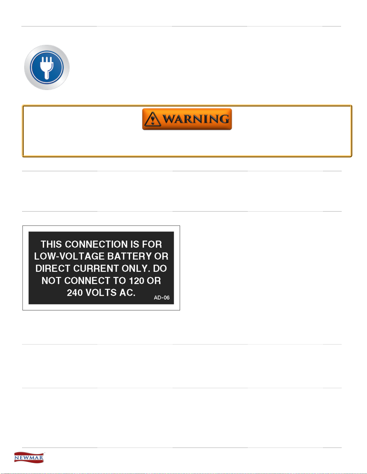
Chapter 6: Electrical
A Newmar coach's electrical and lighting system is designed for maximum reliability, functionality, and
style. Electrical wiring holes in the aluminum frame are ringed with plastic grommets to protect wires
from chafing. This category provides detailed information about the components of your 12 Volt and
120 Volt electrical systems, your chassis and house batteries, as well as your coach management
systems and fuse panels.
Under each sub-category, you have access to owners manuals, user guides, parts and service
manuals, and product specifications for each aspect of your coach's electrical system.
Due to the risk of electrical shock, service should be performed by a qualified electrican or authorized service
technician. The electrical system may have multiple 120/240 volt power sources. All power sources must be
turned off, and any auto generator start features must be disabled prior to servicing.
12 Volt Electrical System
Provides general information about the components and functions of the 12 Volt Electrical System (DC) in Newmar
coaches.
Power Sources
The 12 Volt Electrical System allows certain components to
maintain a low voltage from the battery bank. The battery
bank is controlled by the coach charging system, which
consists of a charge bridge solenoid, a bi-directional isolator
relay delay (BIRD), or a battery isolation manager
(BIM). When the coach engine is running, the alternator
charges the chassis batteries and may assist in charging the
house batteries through the BIM, BIRD, or Charge Bridge.
When the coach is connected to shore power or when the
coach generator is in use (when shore power is
unavailable), the converter or inverter/converter combination
recharges the house batteries, and with the assistance o a
BIM, BIRD, or Charge Bridge, it can also charge the chassis batteries.
In addition to the alternator and converter, the coach may also be equipped with solar panels to provide an
additional option for charging your house batteries.
Alternator
The alternator is a belt-driven component attached to the coach engine and is supplied by the chassis
manufacturer. The alternator supplies power for chassis components such as batteries, lights, wipers, dash HVAC, and
power seats, as well as all of the driver controls located in the cockpit. The alternator charges the chassis batteries, but
with the addition of a BIM, BIRD, or Charge Bridge, it may also assist in charging the coach's house batteries.
Generator
When shore power is unavailable, the generator takes mechanical energy and converts it into alternating current to
supply 120 volts to the coach and charge the coach's house via the converter or inverter/converter and the chassis
batteries via BIRD, BIM, or charge bridge.
The generator is typically located in the front of the unit between the frame rails on diesel coaches. On gas units, the
generator may be located anywhere between the mid and rear section of the coach. Generators can be powered by gas,
liquid propane, or diesel fuel.
© 2016 Copyright Newmar Corporation. All rights reserved. For the most up-to-date version of this content, and for more product-specific information, please refer to Newgle.

Converter and Inverter/Converter Combination
All Newmar coaches are equipped with a converter or inverter/converter combination. A converter transforms alternating
current or shore line power 120 Volts to low-voltage direct current to provide power to the coach's 12 Volt house and
chassis batteries. On the other hand, an inverter transforms direct current to alternating current to provide power to
specified appliances and entertainment systems.
Solar Panel
Some Newmar units are equipped with a 10 Watt solar panel wired to the chassis batteries. Prior models may have a five
or 10 Watt solar panel and may be wired to the chassis-side KIB panel.
Batteries
Please refer to the Battery Basics article for more information.
Power Distribution
Charge Bridge Solenoid
All current model Mountain Aire, London Aire, Essex, and King Aire coaches
use Silverleaf, a computerized coach management system.
One of its many functions is to control the battery charging through the Charge
Bridge Solenoid. The TM102 module monitors the battery state and
senses the house and chassis battery voltage.
When the parameters are met, the TM102 module activates the solenoid,
causing it to bridge or connect the chassis and house battery banks.
For more information on your coach's TM102 module, refer to the SilverLeaf
Functional Guide.
Battery Isolation Manager (BIM)
All current Dutch Star, Ventana, and Ventana LE diesel coaches, as well as
gas coaches with 50 Amp electrical service, use a Precision Circuits all-in-one
Battery Isolation Manager (BIM). The BIM monitors both the chassis and
house battery and is the only place in the coach where they both merge. The
BIM only functions when the engine or generator is running or when the coach
is connected to shore power.
To learn more, visit the Battery Isolation Manager home page.
© 2016 Copyright Newmar Corporation. All rights reserved. For the most up-to-date version of this content, and for more product-specific information, please refer to Newgle.

Bi-Directional Isolator Relay Delay (BIRD)
Battery Disconnect
Newmar uses an Intellitec disconnect relay connected to the battery bank to
disconnect certain loads when placing the coach in storage. Keep in mind
that not all loads are disconnected. This is very important to remember
when a coach is put into storage and is not plugged into shore power.
Before placing the battery disconnect in the "off" position, make sure the
inverter (if equipped) is turned off.
When an older coach is stored while plugged into shore power, do not use
the battery disconnect. If the battery disconnect is used, the chassis
batteries will not receive a charge from the converter or inverter/converter
combination. This is due to the coach battery wire being disconnected,
meaning the BIM or the BIRD will not engage.
The Bay Star Sport has a manual rotary key switch to disconnect power,
which is located in the overhead above the entry door. Fifth wheel products
also used a manual rotary disconnect switch, which were normally located
in the bathroom. All other coaches have a single lighted switch located in
the front overhead that turns off the house voltage.
Current gas coaches with 30 Amp electrical service, as well as
some older diesel coaches, use an Intellitec Bi-Directional
Isolator Relay Delay (BIRD) with a separate solenoid. The
BIRD monitors both the chassis and house battery and is the
only place in the coach where they both merge. The BIRD only
functions when the engine or generator is running or when the
coach is connected to shore power.
To learn more, visit the Bi-Directional Isolator Relay Delay
home page.
When the battery disconnect is 'off', meaning you have disconnected components from the batteries, there are
still some loads on the batteries connected to the hot side of the Battery Disconnect Relay. Some of these
loads may be Radio Memory, Entry Steps, and LP Detector. These will draw from the batteries, even when the
disconnect is 'off'. Pull the fuse for each of the 'HOT' circuits to stop the batteries from being drained.
Fuse Blocks and Mini-Breakers
When a 12 Volt wire is ran, most of the circuits are protected with fuses or mini-breakers. These can be located at
various areas in the coach but are typically located near the main breaker panel. However, they may also be found in
areas such as:
Interior
• Rear bedroom
• Rear bathroom
• Closet
© 2016 Copyright Newmar Corporation. All rights reserved. For the most up-to-date version of this content, and for more product-specific information, please refer to Newgle.
Exterior
• Power cord compartment
• Left, front electrical compartment (located beneath the driver window)
• Front firewall (gas coaches)

Sample: Cord Compartment Mini-Breakers Sample: Cord compartment
Sample: Front stool room Sample: Fuse Block Board
There are also some circuits that are protected with an inline fuse. Some fuse blocks have fixed relays integrated on a
board. The board below is located in the cord compartment.
Basic 12 Volt Power Flow
Since a battery is only an electrical storage component, 120 Volt power must be present to charge the batteries from the
converter or inverter/ converter combination unit. It is necessary to have 12 Volt power supplied from the coach's house
battery bank in order to operate the interior lights and other 12 Volt loads such as Slideout control systems, water pumps,
vent fans, monitoring systems, etc. Most of this power flows through the battery disconnect to the fuse block or minibreakers, which prevents overloading the circuit prior to progressing to the 12 Volt load. There are some 12
Volt circuits that do not go through the house battery disconnect; however, these loads still pass through a fuse or minibreaker before progressing to the load.
When a 12 Volt load or component is not working, both 12 Volt power (+) and 12 Volt ground (-) are needed for
the load to complete the 12 Volt circuit.
© 2016 Copyright Newmar Corporation. All rights reserved. For the most up-to-date version of this content, and for more product-specific information, please refer to Newgle.

120 Volt Electrical System
Provides general information about the components and functions of the 120 Volt Electrical System (AC) in Newmar
coaches.
Power Sources
There are three types of alternating current (AC) power sources available to the coach: shore power, generator power,
and inverter power. Shore power is provided by the RV park or by home service outlets and should be used whenever
possible. Generator power should mainly be used when shore power is not available, specifically while traveling, when
120 Volt power is necessary to run high amperage loads, or when dry camping requires 120 Volt for battery charging.
Inverted power is mainly used for light 120 Volt loads when shore power is not available and generator power is not
desired.
Generator Power
Generator power is produced within the generator and is output through the main wiring to the transfer switch. From the
transfer switch, the power moves to the main breaker box where it is dispersed to individual circuits (outlets) and hardwired components such as a water heater or boiler. From the inverted circuits, generator power will then travel through
the inverter’s internal transfer switch and back to the inverted subpanel to be dispersed through the individual breakers to
the outlets or appliances.
Inverter Power
This type of power starts at the battery bank. The battery bank supplies 12 Volt power through cables to the inverter,
which uses the 12 Volt direct current to produce 120 Volt alternating current. The inverter performs this action by using a
transformer to increase the voltage and modify the higher voltage into a useable alternating current power. Power then
goes to the inverted sub panel, which is dispersed through the individual breakers to the outlets or appliances.
The inverter may provide battery charging while 120 Volts is supplied via the generator or shore power. The inverter
performs this action by using the transformer to decrease the voltage and rectify the alternating current into useable direct
current voltage. This is regulated by internal sensing circuitry based upon the battery bank’s state of charge and several
other factors, depending on the coach's particular inverter brand and type.
Shore Power
Most RV parks provide 30 Amp, 120 Volt at
the site; however, many parks also
provide 50 Amp, 240 Volt service to
accommodate the electrical needs of newer
and larger coaches. Shore power is supplied
to the coach via a power cord. Two sizes of
power cords are found in Newmar coaches:
50 Amp and 30 Amp. The 50 Amp cords are
made up of four conductors #8 stranded wire
and a molded plug. The 30 Amp cords are
made up of three conductors #10 stranded
wire and a molded plug.
Shore power enters through the 30 or 50 Amp
power cord to the power cord reel (if
equipped). From the power cord reel, it
travels to the transfer switch and then to the
main breaker box where it is dispersed to the
individual circuits to supply power to hardwired components such as air conditioners,
30 Amp Plug 50 Amp Plug
The inverted circuits move from the inverter's internal transfer switch to the inverter subpanel (a smaller breaker box).
From the subpanel, the power circulates to the individual breakers and to the electrical outlets and appliances.
water heaters, etc. and then to the inverter (if
equipped).
© 2016 Copyright Newmar Corporation. All rights reserved. For the most up-to-date version of this content, and for more product-specific information, please refer to Newgle.

Shore Power Adapters
Newmar Corporation does not recommend use of adapter, cheater, or dog-bone style connectors that will
modify the existing shore power cord to a different style of outlet. Use of this type of adapter will greatly
reduce the amount of available current in the unit, as well as create the potential for electrical failure and/or
fire.
If an adapter is used, there are three common sizes of power cord adapters available to adjust to a smaller amperage
outlet:
1. 30 amp to 20 amp
2. 50 amp to 20 amp
3. 50 amp to 30 amp
It is important to understand the risks involved and the possible effects of using adapters in conjunction with your coach.
Some of these risks and possible effects include:
• Melted or damaged adapters causing poor connection (or no connection at all)
• Melted or damaged 30 or 50 Amp plugs causing fluctuations in voltage that may damage electronics
• Insufficient amperage causing the tripping of a breaker at the post or a limited use of appliances
Low voltage can also be caused by use of adapters, long extension cords, or extension cords with an insufficient
wire size.
30 amp to 20 amp adapter
50 amp to 30 amp adapter
50 amp to 20 amp adapter
Newmar Corporation cannot assume liability for failures occurring to the RV, its electrical system, or any of its
components from the use of any electrical adapter.
© 2016 Copyright Newmar Corporation. All rights reserved. For the most up-to-date version of this content, and for more product-specific information, please refer to Newgle.

Automatic Transfer Switch
Current coaches with a generator will also have a transfer switch installed in the cord
compartment. An automatic transfer switch converts two inputs and connects them to a
single common output. The shore power cord is connected to one of the inputs, while
the generator is connected to the transfer switch's second input.
Automatic transfer switches are logic-controlled to convert under a given set of
conditions. The transfer switches used in RVs are typically generator priority switches
which connect to shore power under normal use. As soon as the transfer switch detects
the presence of 120 Volt power on the generator input lines, it will switch over to the
generator's inputs and drop the connection to shore power.
Transfer switches are designed so that only one input can be connected at a time in
order to prevent any back feeding of electrical power. In addition, RV transfer switches
generally have a built-in delay allowing the generator to warm up and speed up before
actually switching the load. This prevents stalling or stumbling while the engine is still
cold and not producing full power.
Interior view of a Transfer Switch
Main Service Panel Breaker Box
The main service panel or 120 Volt breaker box is typically located inside a bathroom, bedroom, or front overhead cabinet
depending on the coach model and floor plan. The breaker box contains the main 50 Amp (or 30 Amp if equipped)
breaker and the individual breakers protecting each circuit from overload conditions. Any unit equipped with two air
conditioners or more must have 50 Amp service. The task of the breaker is to “trip” if the current exceeds the amperage
rating on the breaker to prevent damage to the wiring of the circuit.
The breakers are resettable by simply flipping the breaker to the 'off' position, and then back to the 'on' position once the
overload condition is removed. All 120 Volt circuit breakers are located in the main service panel unless the coach
is equipped with an inverter/charger. These units are also equipped with a subpanel.
Breakers positioned next to each other are on different poles in a 50 Amp panel. If only part of the electrical
circuits are working, you may have a poor connection at shore power. In this instance, power is most likely
only being provided to one pole or leg.
Subpanel
The subpanel is a smaller 120 Volt breaker box containing the breakers for the circuits which the inverter is wired to
power. It is typically located near the main breaker box unless the coach is equipped with an Energy Management
System (EMS). In this case, the subpanel is often located within the EMS panel. The subpanel is installed to limit the AC
power use to specific circuits when the electricity is supplied by the inverter. Some inverters may be used to power a
specific circuit. In this case, a subpanel is not used.
50 Amp Energy Management System (EMS)
The 50 Amp Precision Circuits Energy Management System is currently offered as standard equipment on all Canyon
Star, Ventana, and Dutch Star coaches. Its function is to provide power management for certain 120 Volt loads and as a
system of energy management to minimize the overloading and tripping of circuit breakers. The EMS contains a main
distribution panel with a self-contained control module and a remote display panel, which is typically located in the dash
overhead electrical control cabinet.
The EMS control module automatically senses the available power being supplied to the coach. The module determines
whether it is connected to a 50 Amp (240 Volt) or the generator. On 120 Volt service, it is unable to determine if the
source is providing 30, 20 or 15 Amp shore power. Depending on available power, it can control up to seven loads. The
EMS controls air conditioner loads using low-voltage switching and other 120 Volt, heavy-load appliances, such as block
© 2016 Copyright Newmar Corporation. All rights reserved. For the most up-to-date version of this content, and for more product-specific information, please refer to Newgle.

heaters, water heating elements, and air conditioners. The EMS will also control the 2012 Magnum inverter charge rate
or switch to invert depending on the charging status. The charger will only reduce once it is in float status.
The current-sensing relay will display the amperage on each leg. The EMS will start shedding loads and look at the AC
current when it sheds a load, determining when it has enough current available to turn on the load again.
When the EMS sheds a load, it only looks at one leg to see how much of a load was shed. For coaches equipped with
the SilverLeaf system, refer to the SilverLeaf Functional Guide for more information on your EMS.
Converters
All Newmar coaches are equipped with a converter or an inverter/converter combination. Converters are used to
transform alternating current power (120 Volt AC) to direct current power (12 Volt DC). Converters supply the coach with
12 Volt power to operate systems in the coach and provide battery charging.
Newmar currently uses three sizes of converters: 45, 60, and 80 Amp models. Previous units may have a 55 or 75 Amp
converter or two 45 Amp converters with a total of 90 Amps available. When replacing a converter, it is necessary to use
the same size converter to ensure sufficient wiring and breakers for the converter's input and output ratings.
Possible causes of converter failure:
• Overheating caused by cooling fan malfunction or inadequate ventilation causing damage to the converter
• Blown fuses
Inverters
An inverter changes 12 Volt DC power to 120 Volt AC power. Coaches with an inverter only typically use it for powering
the entertainment equipment like the TV, DVD, and Blu-ray players. The inverters used for this purpose are usually 600
watt to 1000 watt (1000 Watt inverters may also power a small refrigerator) and do not have battery charging capability.
The inverters are usually located in a basement compartment of the coach. Some inverters have a remote panel for an
on/off switch in the overhead driver area or above the entry door. When power is supplied by either the generator or
shore power, the inverter merely allows the power to "pass through" and will then stop pulling power from the batteries to
try and supply 120 Volt power. There is a protective breaker on the inverter to prevent circuit overload.
Possible causes for inverter failure:
• Overheating caused by inadequate ventilation causing damage to the inverter
• Overloading the circuit causing "tripped" breakers
Inverter/Converter Combinations
Many Newmar coaches are equipped with inverter/charger combination units, sometimes referred to as an inverter/
converter unit. These units range from 1200 to 3000 Watt and serve as a three stage charger and an inverter.
Coaches equipped with this option will also be equipped with a 120 Volt subpanel.
The subpanel is used to limit the circuits powered by the inverter(s). This is necessary to avoid draining the batteries by
supplying inverted power to all circuits. The subpanel is located next to the main service panel. On units equipped with
an EMS, the subpanel is located in the same breaker box but is separated in the interior of main panel. The coach
battery bank supplies the inverter 12 Volt power and has a high amp fuse link on the positive lead from the batteries and
is located near the battery bank.
The inverter/charger can be controlled by a remote panel, from another system like SilverLeaf, or at the inverter itself.
The remote panel is typically located in the front overhead compartment or above the entry door and is used to control
the inverter and the battery charging functions. If a remote panel is connected to the inverter, then the remote panel
takes priority.
Three-Stage Charging Process
The charging cycle uses three states: bulk, absorption, and float. During the initial bulk stage, the inverter charges at
near its full current ability. This causing the battery voltage to rise over time. After the battery voltage reaches the bulk
voltage setting, the charger starts the absorption stage.
During this phase, the charge rate is gradually reduced while the battery voltage is held near the bulk voltage setting. This
insures that the battery is fully charged. The float stage is initiated when the battery has been held at the bulk voltage
setting for the absorption period. At this point the battery voltage is allowed to fall to the float voltage setting, where it is
maintained until another charge cycle is initiated. This reduces gassing of the battery and keeps it fully charged. A new
three-stage charging cycle is initiated after an AC source is reapplied to the AC input terminals.
© 2016 Copyright Newmar Corporation. All rights reserved. For the most up-to-date version of this content, and for more product-specific information, please refer to Newgle.

Automatic Generator Start (AGS)
On units equipped with AGS, the generator will start and provide 120 Volt power if the incoming shore power voltage is
not present and startup parameters are met.
This function must be enabled in order for the AGS to function properly.
Ground Fault Circuit Interrupt Outlets (GFCI)
The Ground Fault Circuit Interrupt (GFCI) outlets protect the user from ground faults between a hot wire and ground. The
120 Volt electrical outlets in the kitchen and bath area are GFCI protected receptacles. The electrical outlets located in
the Slideouts are wired through the kitchen GFCI. The exterior electrical outlets are wired through the bathroom GFCI.
On units equipped with the floor heat option, a separate GFCI is installed in the bathroom or near the main breaker box.
Units with the holding tank heat pad option will have an additional GFCI located in the basement area; however, the exact
location varies.
The GFCI outlets should be tested at least once a month. The 120 Volt electrical system must be energized in order to
test the GFCI. The reset button needs to be pressed before starting the test. Then push the test button, which
will cause the reset button to pop out, confirming the protected circuits have been disconnected. Push the reset button
again until a click is heard to reactivate the protected circuit. If the GFCI is working properly, the reset button will remain
in the “IN” position. If an item plugged into a Slideout or outside receptacle is not working, check for a tripped GFCI in the
kitchen or bathroom. Likewise, if the floor heat or holding tank heat pads are not working, check the GFCI for that circuit.
The GFCI will not reduce the shock hazard if the short is between a neutral and hot wire or two hot load wires.
120 Volt Outlets
Several 120 volt receptacles are located throughout the interior of the unit. These receptacles require three-pin plugs
that provide proper grounding to protect you from electrical shock. The breaker for the outlets are usually located in the
breaker box. If the breakers are on the inverted circuitry, they will be located in the subpanel near the main breaker box.
Do not use an adapter, cheater, or extension cord that breaks the continuity of the ground circuit to the ground
pin. Never remove the ground pin from a plug in order to connect it to a two-pronged ungrounded outlet.
Batteries
House and Chassis Battery Banks
There are two different battery banks in a Newmar coach: House and Chassis.
The House Battery Bank is necessary to operate everything a customer may require in order to live in the unit. These
batteries can be either 6 Volt deep cycle (all diesel coaches) or 12 Volt deep cycle, depending on the model and brand of
the coach. Newmar house batteries may be serviceable or sealed.
The Chassis Battery Bank supplies power to everything a customer requires to drive the unit. Currently, Newmar's
chassis batteries are all Liquid Lead Acid. Spartan and Ford chassis have serviceable batteries and Freightliner chassis
batteries are sealed. The type and brand of chassis battery may vary depending on coach year, make, and model.
Chassis batteries may need to be disconnected and removed from the coach to maintain proper electrolyte levels
or perform routine battery maintenance. House batteries may be either serviceable Liquid Lead Acid / Flooded or AGM /
Sealed Cell.
© 2016 Copyright Newmar Corporation. All rights reserved. For the most up-to-date version of this content, and for more product-specific information, please refer to Newgle.

The chassis batteries on your motorhome are installed and warranted by the chassis manufacturer. The coach (or
house) batteries on your motorhome are installed by Newmar Corporation, but warranted by the battery manufacturer.
These batteries are used to operate the 12 volt items that are not a direct part of the chassis. Depending on unit the
batteries may be located in the front of the coach under the front cap or may be located on a pull out tray in an outside
compartment.
Chassis Battery Bank Example
House Battery Bank Example
Do not use the motorhome with the coach batteries disconnected.
The chassis batteries are recharged by the vehicle’s electrical system whenever the engine is running, with added BIRD,
BIM, or Charge bridge soleniods the vehicle's charging system will also charge house batteries if parameters are met. A
decline in the coach battery voltage may be noticed while the chassis batteries are being charged.
The converter will automatically charge the coach batteries when the unit is connected to a 120 volt outside power
source. The chassis batteries are isolated from the coach batteries, however with certain parameters met the
BIRD, BIM, or Charge bridge will activate and allow charge to the chassis battery also . This prevents the chassis
batteries from being drained by the interior 12 volt equipment, allowing ample voltage for engine ignition.
Battery Inspection & Care
Remove rings, metal watch bands, and other metal jewelry before working around batteries. Use caution when
using metal tools. If a tool contacts a battery terminal or metal connected to it, a short circuit could occur
which could cause personal injury, explosion or fire.
Disconnect the 120 volt electrical power cord and the negative terminal from the coach batteries before
working on the electrical system.
Remember that when batteries are not used for an extended period of time, they may lose their charge. Periodic charging
of the batteries during storage of the unit will increase the life of the battery. Check the external condition of the battery
periodically. Look for cracks in the cover.
© 2016 Copyright Newmar Corporation. All rights reserved. For the most up-to-date version of this content, and for more product-specific information, please refer to Newgle.

Check the vent plugs and replace them if they are cracked or broken. Keep the battery clean. Accumulations of acid film
and dirt may permit current flow between the terminals, which could drain the battery.
To clean, wash the batteries with a diluted solution of baking soda and water to neutralize any acid present. Rinse
thoroughly with clean water. Foaming around the terminals or on top of the battery is a sign that acid is being neutralized.
Avoid getting the baking soda solution in the battery. Secure all vent caps. Dry the battery cables and terminals to
prevent corrosion. Do not use grease on the bare metal inside the cable terminals. Grease can act as an insulator, and
electricity will not flow through it. A plastic ignition spray will protect the terminals after they have been cleaned.
Do not allow the battery fluid to contact your skin, eyes, fabric, or painted surfaces. The fluid could cause
serious personal injury or property damage. Wear eye protection when working with any battery.
The batteries should be removed and stored in a warm place when not using your motorhome for an extended period of
time. Mark the cables, positive and negative, for easy identification. Batteries are not to be stored on concrete floors. The
batteries require periodic charging during storage. If the motorhome is to be stored for a long period of time, it is
recommended that all of the batteries inside the unit be removed from clocks, radios, smoke alarms, etc. This will prevent
unnecessary drain and corrosion of the batteries. The coach batteries are 6 volt RV/Marine deep cycle batteries.
This type of battery consumes water and must be filled periodically. Please be sure to check the battery water level on a
regular basis. Consult the owner’s manual supplied by the battery manufacturer.
Replacing Your Batteries
Replacement batteries should be the same as was replaced. Any time one battery in a set of batteries is to be replaced,
it is important to have all the batteries in the system tested to assure all are okay. If one defective battery is replaced,
while leaving another weak or defective battery, lowered performance, or ultimately damaging the new or good batteries
can be the result.
Charging batteries give off gasses as the fluids inside boil. Because of this, it is critical to check the battery
fluid levels regularly, particularly after extended periods of heavy use. Be sure to top off any battery that is
showing signs of depleted fluid levels.
Battery Disconnect Switch
The switch is used to disconnect the battery when the unit is stored for any period of time. Pressing downward
disconnects the coach batteries, not the chassis batteries. This is done to prevent the coach batteries from being
drained during storage. It disconnects most of the 12 volt circuitry from the batteries, with the exception of the LP
detector and various memory features. When taking the unit out of storage, press upward to reconnect the batteries.
This will make the 12 volt system ready for use.
Depending on the chassis of the coach, diesel pusher motorhomes may be equipped with a second disconnect switch
strictly for the chassis batteries. If equipped, this “Master Kill Switch” may be located in the rear engine compartment or
chassis battery compartment. This switch disconnects all power to the chassis so that the engine cannot be started. It is
used to prevent accidental ignition when the engine is being serviced.
For More Information
Refer to the product manufacturer's owner's manual and links, as well as the "Battery Basics" article to learn more about
your coach's batteries.
© 2016 Copyright Newmar Corporation. All rights reserved. For the most up-to-date version of this content, and for more product-specific information, please refer to Newgle.

Battery Basics
Introduction
As with anything technical, greater knowledge of the basics may help you increase performance, reliability, and longevity,
as well as prevent future problems with your batteries. This article will provide information regarding your coach
batteries; however, this is only one aspect of your coach's electrical system. To learn more about your batteries' role
within the system, please refer to the 12 Volt Electrical article.
Commercial lead acid batteries have been used for over 150 years. The same chemical principal used to store energy
now was also used many generations ago. Present day chassis battery power requirements are tremendous,
considering today's vehicles and all of the electrical devices that must be supplied. All of these electronics require a
reliable power source, and poor battery condition may lead to expensive electronic component failure. A battery is like a
piggy bank - it stores energy, but cannot produce it. If you continue to withdraw without making any deposits, you will
soon have nothing left.
Life Span of a Battery
Not long ago, motor homes only used a single 12 Volt house battery. Today, however, it is standard to have at least two
batteries, and up to 16 total in some Newmar coaches, powering inverters up to 3000 watts. As energy requirements
increase, the average battery life decreases. The life span of a deep cycle battery will vary considerably with how it is
used, how it is maintained and charged, temperature, and other factors. The life span is dependent upon usage but often
ranges between six months to 48 months. Only 30 percent of all batteries actually reach the 48 month mark.
One simple way to extend battery life is to hook it up to a solar charger during the off months.
It is best practice to change the complete battery bank when a new battery becomes necessary, as the battery bank is
only as good as the weakest cell.
Common Battery Terms
Ampere (Amp) - A unit that defines the flow rate of electricity (current) in a circuit.
Amp Hour (AH) -
for 20 hours.
Example: A 100 AH rated battery is determined like this: Draw from the battery for 20 hours provides a total of 100 amp
hours, translating to about five amps an hour (5 amps x 20 hours = 100 AH). However, it is important to know that the
total time of discharge and load applied is not a linear relationship. As your load increases, your realized capacity
decreases. This means if you discharged that same 100 AH battery by a 100 amp load, it will not give you one hour of
runtime. On the contrary, the perceived capacity of the battery will be about 64 AH.
Cold Cranking Amps (CCA) - Measures the number of amps a battery can deliver at 0° F for 30 seconds without
dropping below 7.2 Volts (1.2 Volts per cell). A high CCA battery rating is especially important in engine-starting battery
applications and in cold weather. This measurement is not particularly important in deep cycle batteries, though it is the
most commonly known battery measurement.
Cranking Amps (CA) - Measures available current at 32° F and is also called marine cranking amps (MCA).
Depth of Discharge (DOD) - Measures the percent of rated capacity to which a cell or battery is discharged. It is the
reciprocal of a battery's state of charge. Example: A battery that has a depth of discharge of 45 percent has a state of
charge of 55 percent.
Reserve Capacity (RC) - Measures the number of minutes a fully charged battery can continuously deliver 25 amps at
80 ° F before the voltage drops below 10.5 Volts. This measurement represents the amount of time the battery can
operate if a charging system failure occurs.
Electrolyte Specific Gravity (battery test) - Unit of measure which compares the weight of the electrolyte solution to
the weight of water. This test is performed with a hydometer or a refractometer that is made for testing batteries. This
type of test is used to determine the battery's state of charge; however, it cannot be used on sealed batteries.
Measurement of electrical storage capacity on a deep cycle battery. The standard amp rating is taken
Battery Types
Liquid Lead Acid / Flooded
The Lead Acid battery consists of a plastic container with cells molded into it. Each cell contains plates, lead, and lead
oxide (various other elements are used to change density, hardness, porosity, etc.) with 35 percent sulfuric acid and a
© 2016 Copyright Newmar Corporation. All rights reserved. For the most up-to-date version of this content, and for more product-specific information, please refer to Newgle.

65 percent water solution.This solution is called an electrolyte, which causes a chemical reaction that releases electrons.
When testing a battery with a hydrometer, the amount of sulfuric acid in the electrolyte is measured. If the reading is low,
the chemistry that makes electrons is lacking. The sulfur is now resting on the battery plates and will remain there until
the battery is recharged and the sulfur returns to the electrolyte.
Absorbed Glass Mat (AGM) / Dry Cell
The Absorbed Glass Mat battery is just like a flooded battery, except the electricity is maintained in the glass mats, as
opposed to freely flooding the plates. Very thin fibers are woven into a mat to increase the surface area to hold sufficient
electrolyte on the cells for their lifetime. The construction allows the electrolyte to remain suspended in close proximity
with the plate's active material, enhancing both the discharge and recharge efficiency.
When Deep Cycle AGM batteries are not discharged more than 60 percent, the cycle life could be approximately a few
hundred cycles. If you do not use or operate your equipment daily, AGM batteries will hold their charge better than most
other types. In most cases AGM batteries will provide a greater life span and cycle life than a Wet Cell battery.
AGM batteries are also often referred to as Sealed Regulated Valve, Dry Cell, Non-Spillable, and Valve-Regulated Lead
Acid batteries.
Gel Cell Batteries
The Gel Cell is similar to the AGM battery because the electrolyte is suspended; however, the AGM battery is still
considered to be a wet cell. The electrolyte in a Gel Cell has a silica additive that causes it to set (gel) or stiffen. The
recharge voltage on this type of cell is lower than the other types of lead acid batteries, due to the likelihood of
an adverse reaction to over-voltage charging. Gel Cell batteries are best used in very deep cycle applications and may
last longer in hot weather applications.
House and Chassis Battery Banks
There are two different battery banks in a Newmar coach: House and Chassis.
The House Battery Bank is necessary to operate everything a customer may require in order to live in the unit. These
batteries can be either 6 Volt deep cycle (all diesel coaches) or 12 Volt deep cycle, depending on the model and brand of
the coach. Newmar house batteries are serviceable.
The Chassis Battery Bank supplies power to everything a customer requires to drive the unit. Currently, Newmar's
chassis batteries are all Liquid Lead Acid. Spartan and Ford chassis have serviceable batteries and Freightliner chassis
batteries are sealed. The type and brand of chassis battery may vary depending on coach year, make, and model.
Chassis batteries may need to be disconnected and removed from the coach to maintain proper electrolyte levels
or perform routine battery maintenance. House batteries may be either serviceable Liquid Lead Acid / Flooded or AGM /
Sealed Cell.
Parallel Battery Wiring
Parallel battery wiring refers to two or more batteries with all positive (+) terminals hooked together and all negative (-)
terminals hooked together. This results in a battery voltage similar to that of the individual batteries, typically 12 Volt, to
boost battery capacity. Two identical batteries wired parallel will provide twice the electrical storage capacity of one
battery, without increasing voltage.
Series Battery Wiring
Series wiring refers to two or more batteries hooked together, with opposite terminals connected. The positive (+)
terminal of the first battery should be connected to the negative (-) terminal of the second battery. The resulting voltage
is the sum of the individual batteries. For example, if two six Volt batteries are hooked together, the resulting voltage will
be 12 Volts.
Series/Parallel Wiring
Series/ Parallel battery wiring is used on Newmar units when four or more 6 Volt batteries are used for the house battery
bank. Since 12 Volts is the desired working voltage from the battery bank, the batteries are connected to provide 12 Volts
with more capacity. Two 6 volt batteries wired together in a series create a 12 Volt battery bank. Two or more of the 12
Volt battery banks can be connected together in a parallel format to provide more capacity.
In situations where multiple batteries are connected in a series, parallel or series/parallel, replacement batteries should
be the same size, type, and manufacturer (if possible). Age and usage level should be the same as the companion
batteries.
Below are some examples of Newmar battery bank wiring:
© 2016 Copyright Newmar Corporation. All rights reserved. For the most up-to-date version of this content, and for more product-specific information, please refer to Newgle.

Battery Cycle vs. Battery Life
A battery cycle is one complete discharge and recharge cycle (100 percent to 20 percent, and then back to 100 percent).
Battery life is directly related to how deep the battery is cycled each time. The most common cycles are 10, 20, and 50
percent. Be cautious of ratings that list the number of cycles, unless it also states how low the battery is being
discharged.
For example, telephone type (float service) batteries have been advertised as having a 20-year life. However, the rating
only stands true at five percent depth of discharge (DOD), and the life span is much less when used in an application
where the batteries are cycled deeper on a regular basis. Those same batteries are rated at less than five years if cycled
to 50 percent.
If a battery is discharged to 50 percent every day, it will last about twice as long as if it is cycled to 80 percent DOD. If
cycled only 10 percent DOD, it will last about five times as long as one cycled to 50 percent. The most practical number
to use is 50 percent DOD on a regular basis for the best use of effective storage and cost.
In addition, there is an upper limit. A battery that is continually cycled down five percent or less will usually not last as
long as one cycled down 10 percent. At very shallow cycles, lead dioxide tends to build up in clumps on the positive
plates rather than in an even layer.
Battery State/Voltage Chart
State of Charge Specific Gravity 12 Volt 6 Volt
100% 1.265 12.7 6.3
75% 1.225 12.4 6.2
50% 1.190 12.2 6.1
25% 1.155 12.0 6.0
Discharged 1.120 11.9 6.0
This battery state voltage chart is used as an example. Your specific battery manufacturer's chart may vary.
Note: Both voltage and specific gravity tests should be performed with no load on the batteries and without any supplied
charging. Turn off all draws and charging. Allow the batteries to stabilize, and then proceed with the test.
Battery Maintenance
Battery maintenance is an important issue often overlooked by many RV owners and technicians. As batteries age, their
maintenance requirements change. This means longer charging time and/or higher finish rate (higher amperage at the
end of the charge). Usually older, serviceable (unsealed) flooded batteries need to be watered more often, as their
capacity decreases over time.
Before attempting battery maintenance, make sure all coach power sources are disabled (ignition, generator,
shore power, inverter).
Common Causes of Premature Battery Failure
Source: http://www.batterystuff.com/kb/artic...ry-basics.html
1. Deep discharges (leaving your lights on)
2. Misapplication
© 2016 Copyright Newmar Corporation. All rights reserved. For the most up-to-date version of this content, and for more product-specific information, please refer to Newgle.

3. Replacement using an undersized battery not meeting Newmar's OEM specifications
Loss of electrolyte due to overheating or overcharging.
4.
5. Undercharging or loose alternator belt
6. Excessive vibration (due to loose clamp or hold down on battery)
7. Corrosion
8. Freezing (A fully-charged vehicle battery will not freeze until the temperature is -75° F. Frozen batteries are
not warrantable.)
9. Failure to charge a battery during a period of six months or more (Inactivity can be extremely harmful to all lead
acid batteries.)
Battery Safety Guidelines
Prior to handling or working with a lead-acid battery, consult your battery owners' manual for instructions and
safety precautions.
Lead-acid batteries contain hydrogen-oxygen gases that may be explosive and sulfuric acid that may cause severe
burns. To avoid injury, observe these precautions when handling or working with a lead-acid battery:
• Wear ANSI (American National Standards Institute) approved safety glasses or goggles, as well as a face
shield.
• Wear proper clothing to protect your face, hands, and body.
• Work in a well-ventilated area.
• Never lean over a battery while boosting, testing, or charging.
• Keep all ignition sources away from the battery. Cigarettes, flames, or sparks could cause a battery to explode.
• Always shield eyes and face from the battery.
• Do not charge or use booster cables or adjust post connections without proper instructions and training.
• Keep vent caps tight and level.
• In the event of an accident, flush eyes or skin with water, and call a physician immediately.
• Keep out of reach of children.
Cleaning the Battery
1. The battery should be cleaned using a baking soda and water solution. This should be a mixture of a couple of
tablespoons of baking soda per pint of water.
2. Both house and chassis battery cable connections need to be cleaned and tightened, as battery problems are
often caused by dirty and loose connections.
Checking the Fluid Level
1. A serviceable battery needs to have the fluid level checked. If the battery has removable vent caps, they can
be twisted or pried off with a flat-head screwdriver. Once removed, the individual vent wells can be seen.
2. Look down into each individual cell to make sure that the water is covering the lead plates and is at the
proper level.
3. Add water to any cells that are low on water. Ideally, the water level should be 1/8" below the bottom of the tubes
(there are six tubes in a 12 Volt battery) that go down into the battery. To avoid damage to the battery, make sure
the fluid level never drops below the tops of the lead plates in each of the cells. Always use distilled water to fill the
battery to prevent battery contamination.
4. Do not overfill battery cells. Adding too much water may result in acid overflow and damage around the battery.
In addition, warmer weather may cause natural fluid expansion, forcing excess electrolytes from the battery.
© 2016 Copyright Newmar Corporation. All rights reserved. For the most up-to-date version of this content, and for more product-specific information, please refer to Newgle.

Correct Fluid Level
Preventing Corrosion
Newmar sprays the battery connections once they are tightened with a battery protector and sealer to help prevent
corrosion. When performing battery maintenance, you should reseal the battery terminal connections. The following
measures may also prevent future corrosion:
• Use a small bead of silicone sealer at the base of the post where it meets the battery case. Place a felt battery
washer over the post and into the bead of silicone.
• Coat the washer with high temperature grease or petroleum jelly (Vaseline), then place the cable on the post and
tighten.
• Coat the exposed cable end with the grease. The gas condensation on metal parts of the battery cause most
corrosion issues.
Cord Reels
Cord reels provide the ease and convenience of storing the shore power electrical cord in a neat and compact space
with the assistance of motorized retraction.
Operating Instructions
Pull out the power cord and plug into the appropriately rated electrical outlet. Make sure the power source is providing the
correct voltage before plugging in the shore cord.
To store, disconnect the cord from the power source outlet. Remove the cord from the
pocket in the compartment, and press and hold the momentary switch to retract and roll
up the power cord as needed.
For More Information
Refer to the product manufacturer's owner's manual and links to learn more about your coach's cord reel.
© 2016 Copyright Newmar Corporation. All rights reserved. For the most up-to-date version of this content, and for more product-specific information, please refer to Newgle.

Dash Electrical Systems
The dashboard may contain several gauges and controls you have not previously used. Become familiar with
all of these devices and their operation before starting out.
For More Information
Refer to your chassis manufacturer's owner's manual and links to learn more about your coach's dash electrical system,
including information about instrumentation panel, controls, and switches.
Energy Management Systems
The energy management and auto generator start systems work behind the scenes to monitor the power supply and
demand within the coach.
The system is designed to minimize the occurrence of tripped breakers for shore power and the generator while heavy
loads are being used. The system turns off other loads temporarily while heavier loads are in use and restores power
when heavy loads are turned back off. When 50 amp service is available, no action is required; however, 30 amp service
(or less) requires setting the value of incoming power to be selected.
Whenever possible, connect coaches equipped with 50 amp shore power cord to 50 amp service, and connect
coaches with 30 amp shore power cords to 30 amp service accordingly. It is the best practice to avoid using
adapters and cheater cord devices.
Auto generator features may vary by coach model and options. Most AGS systems start the generator if shore power is
unavailable and the HVAC system signals for air conditioner operation. Many systems will also start if automatically if
battery levels reach the preset values.
For More Information
Refer to the product manufacturer's owner's manual and links to learn more about your coach's energy management
system.
Fuse Panels
Class A: Ford Fuse Panels
Inside of the Coach
On a class A coach, the house fuse panel, which controls most of the components and appliances inside the coach, is
located in the bathroom. This panel contains fuses and breakers that are connected to all main appliances in the coach,
from the refrigerator and television to the lights in the bedroom and slideouts. There are also some external components
that are fused in the house fuse panel. For example, the fuses for the water pump, water heater, awning, and basement
storage lights are located in this panel.
On Canyon Star 3911 models (handicap accessible units), this panel is located on the back wall of the
bedroom, next to the 120 volt breaker panel.
© 2016 Copyright Newmar Corporation. All rights reserved. For the most up-to-date version of this content, and for more product-specific information, please refer to Newgle.

The Ford chassis fuse panel is located on the sidewall, left of the driver’s feet. This fuse panel supplies power to exterior
lights, the tow plug, and the wipers. For exact details, see the Ford manual.
The Newmar fuse panel contains the chassis battery and ignition-powered fuses and is located on the firewall under the
dash. This panel controls many of the components in the dash, the clearance/fog lights, and the engine compartment
lights. The fuses for the dash blower, AC condenser, overhead fan, and power visor are also located in this panel.
Newmar Fuse Panel Example
Class A House Fuse Panel Example
Outside of the Coach
House battery and disconnect fuses are located under the hood of the coach. These fuses control the battery boost,
battery disconnect, and entrance steps. In this same location, there are also 12 volt circuit breakers that provide power to
the ignition, house fuse panel, inverter, and the power seats (if equipped).
Diesel Pusher: Spartan or Freightliner Fuse Panels
Inside of the Coach
On a diesel pusher coach, the house fuse panel, which controls most of the components and appliances inside the
coach, is located in the bathroom or in the front overhead next to the 120 volt breaker panel. This panel contains fuses
and breakers that are connected to the main appliances in the coach, from the refrigerator and television to the lights in
the bedroom and slideouts. There are also some external components that are fused in the house fuse panel. For
example, the fuses for the water pump, water heater, security lights, and basement storage lights are located in this
panel.
Outside of the Coach
House battery and disconnect fuses are located in the compartment with the shore power cord. This fuses control the
battery boost, battery disconnect, keyless entry, hydronic heat, LP detector, and entrance steps. In this same location,
there are also 12 volt circuit breakers that provide power to the house fuse panel, slideout motors, power awnings, and
the entry step.
The Freightliner and Spartan chassis fuse panels are located in the left front baggage compartment under the driver’s
seat. An additional chassis circuit fuse panel is located in the chassis battery compartment on the rear passenger side of
the coach. Both the Freightliner and Spartan chassis manuals contain detailed information on what fuses are located in
these panels.
The Newmar KIB fuse panel is also located in the left front baggage compartment under the driver’s seat. This panel
contains fuses that power the dome light, front visor, and the solar panels (late 2015 model year), as well as for the
entrance step, back-up monitors, navigation, cargo lights, and keyless entry. The ignition lock-out for the slideouts and
shades is also located on this fuse panel.
For More Information
Refer to the product manufacturer's owner's manual and links to learn more about your coach's fuse panels.
© 2016 Copyright Newmar Corporation. All rights reserved. For the most up-to-date version of this content, and for more product-specific information, please refer to Newgle.

Example of a KIB Fuse Panel
Shore Power Compartment Fuse Example
Generators
These brief operation instructions are for quick reference only. Any quick start instructions provided should
not take the place of the complete Operation Manual provided by this item's manufacturer.
Your generator may be located in a side compartment or in the front of the coach in between the frame rails of the
chassis. Some generators are mounted on slides for easy access andmay need to be unlocked before free movement is
allowed. The generator is wired into the Automatic Transfer Switch and will power all of the 120 volt circuits in your coach.
The main breakers for the output legs are located on the generator start panel.
Maintaining the Generator
Before starting your generator for the first time each day, and subsequently after each eight-hour run cycle, perform the
following checks to make sure it is ready to be used.
1. Make sure the carbon monoxide detectors in your unit are working.
2. Check for signs of fuel or exhaust leaks.
3. Make sure there is adequate clearance around the generator for proper ventilation. Also check for sloping
ground or any other obstructions that may have occurred. Tall grass or other items that come in contact with the
generator may interfere with ventilation or cause a fire.
4. Check the oil and coolant levels, and inspect for leaks.
5. Check the battery connections to make sure they are tight and clear of corrosion.
6. Inspect the generator compartment for road debris or damage that might affect the performance or safety.
7. Turn off major appliances (such as air conditioners, televisions, and other electronics that may excessively load
the generator or may be sensitive to initial voltage surges).
The hour meter installed on the generator calculates the number of running hours of the generator motor. This is used for
maintenance schedules. Regular oil changes and other maintenance performed at the prescribed intervals will greatly
extend the life of your generator.
© 2016 Copyright Newmar Corporation. All rights reserved. For the most up-to-date version of this content, and for more product-specific information, please refer to Newgle.

Operating the Generator
The generator can be started from the rocker switch on the dash, from other remote start switches (if equipped), from the
start switch on the generator itself, or from the SilverLeaf touchscreen (if equipped).
1. To start the generator, rock the switch to the “start” position.
2. Release the switch once the generator has started. There may be a momentary delay in the Automatic
Transfer Switch engaging to pass the electricity on from the generator.
3. After the generator has started, wait until the transfer switch has engaged before turning on any of the
appliances.
Excessive cranking can damage the starter motor. Do not crank the generator more than 30 seconds at a time,
and allow at least two minutes before trying again if the first attempt fails.
4. To stop the generator, press the rocker switch to the STOP position.
Failure to turn off the 120 volt appliances when starting or stopping the generator may damage the transfer
switch and/or electrical appliances.
Generator Safety
Vehicles and equipment powered by internal combustion
engines and placed in recreational vehicles, such as a
generator, can cause carbon monoxide poisoning or
asphyxiation, which could result in death or serious injury.
Carbon monoxide is a colorless, odorless gas that is lethal.
Symptoms of carbon monoxide poisoning are:
• Dizziness
• Nausea/Vomiting
• Headache
If you experience any of these symptoms, get fresh air
immediately. If symptoms persist, seek medical attention
right away.
Shut down the Genset, and do not operate it again until it
has been inspected and repaired.
Always make sure the carbon monoxide detector in your unit is operating correctly.
• Weakness
• Sleepiness
• Inability to think coherently
If your coach contains an Energy Management System, 8kw generator, and three roof air conditioners, the
combined load may exceed the capabilities of the generator. Please remember to turn off one of the air
conditioners as the 8kw generator is not intended to run all three roof air conditioners at the same time.
© 2016 Copyright Newmar Corporation. All rights reserved. For the most up-to-date version of this content, and for more product-specific information, please refer to Newgle.

Diesel Generators
The generator in your coach runs on the same diesel fuel as
your main engine. The diesel fuel is drawn through a
separate supply tube that is positioned in the tank in a
manner that will not allow the generator to draw fuel and run
if the tank level dips below the ¼ level.
Depending on the ambient temperatures, the generator may
pre-heat prior to cranking. This pre-heat condition is noted by
flashing the light on the generator start switch until the cycle
is complete (up to 15 seconds). Once it has pre-heated
sufficiently, the starter will engage and the engine will start.
It is critical that the AGS system be turned off any time the generator is going to be serviced. Failure to
deactivate the AGS system may result in damage, injury, or death if the Genset should start unexpectedly.
Also, if the AGS system is set and the generator is turned off at any switch, it will clear the AGS settings.
Gas Generators
The generator in your coach runs on the same fuel as your
main engine. The fuel is drawn through a separate supply
tube that is positioned in the tank in a manner that will not
allow the generator to draw fuel and run if the tank level dips
below the ¼ level.
For More Information
Refer to the product manufacturer's owner's manual and links to learn more about your coach's generator.
Inverters and Converters
Inverters
The inverter modifies direct current to alternating current to provide power to specified appliances and entertainment
systems. The inverter performs this action by using a transformer to increase the voltage and modify the higher voltage
into a useable alternating current power. For this function to occur, the inverter must be powered, set up, and turned on. A
variety of inverters are used by Newmar; however, most have a control panel located in the overhead cabinet near the
battery disconnect.
Inverter/Converter Combination Units
The inverter/ converter combination provides battery charging and allows the 120 volt power from shore power or the
generator to pass through the inverter. The inverter performs this charging action by using the transformer to decrease
the voltage and rectify the alternating current into useable direct current voltage. This is regulated by internal-sensing
circuitry based upon the battery bank’s state of charge and several other factors, depending on the coach's particular
inverter brand and type. This type of unit also performs the inverter function. For this function to occur, the inverter must
be powered, setup and turned on. A variety of combination units are used by Newmar; however, most have a control
panel located in the overhead cabinet near the battery disconnect.
© 2016 Copyright Newmar Corporation. All rights reserved. For the most up-to-date version of this content, and for more product-specific information, please refer to Newgle.

Converters
A converter transforms alternating current or shore line power 120 volts to low-voltage direct current to provide power to
the coach's 12 volt house and chassis batteries. This function occurs automatically when 120 volts are supplied to the
converter.
For More Information
Refer to the product manufacturer's owner's manual and links to learn more about your coach's inverter, converter, or
inverter/converter combination unit.
Lighting
A Newmar coach's electrical and lighting system is designed for maximum reliability, functionality, and style.
Your coach may feature traditional on/off switches or multi-switch touch panel light and accessory switch panels. Located
throughout the unit, these switching devices are used to turn lights on and off, as well as to operate power shades and
window treatments. Many coach models boast LED accent lights and new cloth-shaded LED wall sconces customdesigned for Newmar.
Operating Instructions
Control can be as simple as flipping the switch or touching the switch panel to operate the light or accessory you desire.
Some lights may also have dimming features, allowing you to adjust the interior lighting for mood or comfort.
For More Information
Refer to the product manufacturer's owner's manual and links to learn more about your coach's lighting system.
Receptacles and Accessory Chargers
Newmar coaches are framed 16 inches on center, allowing the best placement of outlets, switches and other
components.
120 Volt Outlets
Several 120 volt receptacles are located throughout the
interior of the unit. These receptacles require three-pin plugs
that provide proper grounding to protect you from electrical
shock. The breaker for the outlets are usually located in the
breaker box. If the breakers are on the inverted circuitry, they
will be located in the sub-panel near the main breaker box.
Do not use an adapter, cheater, or extension cord that breaks the continuity of the ground circuit to the ground
pin. Never remove the ground pin from a plug in order to connect it to a two-pronged ungrounded outlet.
© 2016 Copyright Newmar Corporation. All rights reserved. For the most up-to-date version of this content, and for more product-specific information, please refer to Newgle.

Ground Fault Circuit Interrupt Outlets (GFCI)
The Ground Fault Circuit Interrupt (GFCI) outlets protect the user from ground faults between a hot wire and ground. The
120 volt electrical outlets in the kitchen and bath area are GFCI protected receptacles. The electrical outlets located in
the slideouts are wired through the kitchen GFCI. The exterior electrical outlets are wired through the bathroom GFCI. On
units equipped with the floor heat option, a separate GFCI is installed in the bathroom or near the main breaker box.
Units with the holding tank heat pad option will have an additional GFCI located in the basement area; however, the
exact location varies.
The GFCI outlets should be tested at least once a month. The 120 volt electrical system must be energized in order to
test the GFCI. The reset button needs to be pressed before starting the test. Push the test button, which will cause the
reset button to pop out, confirming the protected circuits have been disconnected. Push the reset button again until an
audible click signifies the reactivation of the protected circuit. If the GFCI is working properly, the reset button will remain
in the “IN” position. If an item plugged into a slideout or outside receptacle is not working, check for a tripped GFCI in the
kitchen or bathroom. Likewise, if the floor heat or holding tank heat pads are not working, check the GFCI for that circuit.
The GFCI will not reduce the shock hazard if the short is between a neutral and hot wire or two hot load wires.
Accessory Chargers
Your coach may have wireless charging devices built into
your bedroom dresser, as well as into the dash. These
devices are designed to charge your cell phone without ever
having to plug it in; however, not all phones are compatible
with this technology.
For More Information
Refer to the product manufacturer's owner's manual and
links to learn more about your coach's receptacles and
accessory chargers.
Transfer Switches
Your unit may be equipped with an automatic transfer switch. The transfer switch allows your coach to be powered by
more than one power source, while only allowing one active power source connection at a time. When the generator is
turned on, this switch automatically transfers to generator power.
There will be a slight delay between the start of the generator and the electrical connection. This delay allows the
generator to reach normal operating speed without needing to supply a required load. When the unit is plugged into
shore power, an audible click will be heard in the transfer switch box. The sound is normal and indicates that the relay
inside the transfer switch is engaging the outside power source.
Due to the risk of electrical shock, service should be performed by a qualified electrican or authorized service
technician. The electrical system may have multiple 120/240 volt power sources. All power sources must be
turned off, and any auto generator start features must be disabled prior to servicing.
For More Information
Refer to the product manufacturer's owner's manual and links to learn more about your coach's transfer switch.
© 2016 Copyright Newmar Corporation. All rights reserved. For the most up-to-date version of this content, and for more product-specific information, please refer to Newgle.

© 2016 Copyright Newmar Corporation. All rights reserved. For the most up-to-date version of this content, and for more product-specific information, please refer to Newgle.

Chapter 7: Electronics
Multiple coach functions can be controlled at the tips of your fingers, including surveillance and security,
lighting, holding tank monitoring, and if equipped, the total coach management system. This category
provides detailed information about each of the electronic components available in your coach.
Under each sub-category, you will have access to owners manuals, user guides, parts and service
manuals, and product specifications for each of the electronics available in your Newmar coach. For
detailed information see your owner manual for the specific item or refer to Newgle.
Audio-Visual Equipment information is located in the Entertainment Systems category.
Camera and Video Monitoring Systems
This closed circuit television system features cameras mounted on the exterior of your coach and is connected to the indash video screen. This system comes on automatically when you put the transmission in reverse to allow you to see
behind your unit when backing up. Additionally, it can be manually turned on in transit to allow you to monitor your towed
vehicle or for additional assistance in passing maneuvers.
Rear View Cameras
Installed as a standard feature, the rear view monitor system assists the driver in the backing and parking of the vehicle.
This system consists of a camera mounted on the rear cap and a monitor located on the dash. With the MODE switch in
the “MANU” position, the monitor will be on when the ignition is turned on. With the MODE Switch in the “AUTO” position,
the monitor will display the picture from the camera when the vehicle transmission is placed in reverse (R).
Side View Cameras
As an option for the rear vision system, your unit may be equipped with “side view” cameras. These cameras are tied into
the rear vision system and are activated by the turn signals. When a turn signal is activated, the monitor will switch to
display that side of the unit. If the rear vision monitor is turned on manually, you can toggle through the cameras by using
the “source” button, allowing you to stay on any given camera that you choose.
For More Information
Refer to the product manufacturer's owner's manual and links to learn more about your coach's cameras and video
monitoring system.
Chassis Monitoring Systems
The coach information and trip management computer is designed for motorhomes and consists of multiple parts:
• A control pad
• Computer (behind dash)
By collecting data from the sources listed above, as well as from the electronic engine computer, the system collects,
analyzes, and saves data in its memory, and then displays information on the rear vision monitor.
The ignition key must be turned on for the system to display information.
• Compass and temperature sensors (optional)
• Tire pressure sensor/transmitters and receiver (optional)
For More Information
Refer to the product manufacturer's owner's manual and links to learn more about your coach's chassis monitoring system.
© 2016 Copyright Newmar Corporation. All rights reserved. For the most up-to-date version of this content, and for more product-specific information, please refer to Newgle.

Navigation Systems
Your coach may be equipped with a GPS based Navigation system. This system uses GPS technology to guide you
through maps and information for traveling assistance. It features voice prompts and touchscreen technology to make
scrolling through the menus and getting information incredibly easy.
The navigation feature is intended to assist you with guidance to your destination.
The navigation system is NOT intended to replace, supersede, or take precedence over any traffic signs, street
signs, hazard signs, etc.
The system may need software and map updates. Updates are not warrantable issues, as roadways change over time
and construction takes place, the maps and/or systems may become obsolete. It is the driver's responsibility to make
sure the roads are safe and appropriately navigated and roadway weight limits and clearances are rated for the vehicle
you are driving.
For More Information
Refer to the product manufacturer's owner's manual and links to learn more about your coach's navigation system.
Holding Tank Monitoring
The monitor panel allows you to check the approximate levels in the fresh, gray, and black water holding tanks, as well
as propane levels (if equipped), and the battery condition. The monitor panel is generally located above or near the
entrance door. An additional monitor panel may be located in the basement water compartment.
Coaches Not Equipped with SilverLeaf
For coaches not equipped with the SilverLeaf system, simply
press the "Levels Check" button to check the tank level
statuses. The levels will show on the digital display.
Monitor Panel Calibration
The monitor panel has been calibrated for accuracy prior to
leaving the factory and should not need to be adjusted. In the
event that the system does not read accurately, then recalibration may be necessary. Follow the manufacturer's
procedures for re-calibration for your specific product. It is
recommended to have a qualified service technician perform
the re-calibration procedure.
Coaches Equipped with SilverLeaf
For coaches equipped with the SilverLeaf system, the holding tank levels
are displayed on the SPX 300 display in the water compartment. Tank
levels may also be checked using the SilverLeaf touchscreen. Refer to the
SilverLeaf functional guide for more information.
Monitor Panel Calibration
The monitor panel has been calibrated for accuracy prior to leaving the
factory and should not need to be adjusted. If a tank sensor needs to be
replaced, it is recommended to have a qualified service technician perform
the re-calibration procedure through the SilverLeaf system.
For More Information
Refer to the product manufacturer's owner's manual and links to learn more about your coach's holding tank monitoring
system.
© 2016 Copyright Newmar Corporation. All rights reserved. For the most up-to-date version of this content, and for more product-specific information, please refer to Newgle.

Lighting Controllers
Lighting controllers switch the lighting circuits on and off. Select coach models may also have light dimming capability
integrated as well. The system works behind-the-scenes to allow the coach to have multiple switch locations and
configurations.
For More Information
Refer to the product manufacturer's owner's manual and links to learn more about your coach's lighting controllers.
Security and Keyless Entry Systems
Your coach may be equipped with an optional security system (on select models). This system uses a variety of
sensors and switches to guard your unit and its contents. When armed, the system protects the entry door, the battery
compartment, and the front driver's side compartment area.
Many Newmar coaches are equipped with a keyless entry system, which will allow for entry into the coach without the
use of a key. It requires the user to have the correct code to unlock the door. Some coaches also have the same feature
for the storage compartments.
Equipped units are shipped from the factory with a standard access code. When the unit is purchased, it is recommended
that the customer obtain technical assistance in reprogramming a new access code while taking delivery of the unit from
the dealer.
For More Information
Refer to the product manufacturer's owner's manual and links to learn more about your coach's security and keyless
entry system.
© 2016 Copyright Newmar Corporation. All rights reserved. For the most up-to-date version of this content, and for more product-specific information, please refer to Newgle.

© 2016 Copyright Newmar Corporation. All rights reserved. For the most up-to-date version of this content, and for more product-specific information, please refer to Newgle.

Chapter 8: Entertainment Systems
Newmar partners with the most prestigious names in mobile lifestyle, entertainment and technology.
These brands are leaders in their fields – and legends in providing customers with new, unsurpassed
levels of quality and reliability. Best in class performance from names you can trust. Stay entertained
on the road and off, with spectacular visual and sound options from industry leaders.
This section provides information on entertainment components, including televisions, dash-mounted
audio equipment, multi-disc players, home theater systems, and satellite antennas. Such components
may be located within your coach's living room, bedroom, cargo area, or even outside of
your unit in an optional exterior entertainment center.
Some of the components are optional and may not have been installed in your unit.
Exterior Entertainment Center
For your convenience and pleasure, an Exterior Entertainment Center may be an option on selected floorplans. It may be
located in either a basement compartment or in the sidewall of the passenger side of the coach. Depending on the year,
model, and floorplan of your coach, this entertainment center features an flat screen television, and may feature an AM/
FM/CD stereo and speakers to provide outside music when desired. Some coach models feature a sound bar instead,
and may also have an audio selector switch.
The television is mounted on a swivel bracket that allows you to swing the television out and away from the coach to
provide better viewing angles. To release the television from its retainers, grasp the sides of the television firmly and pull
it directly toward you. It will release and swing freely to the desired viewing position. To store the television for travel,
swing it back into the opening, making sure that it is fully latched.
The external stereo can be used to listen to AM and FM broadcasts, as well as to play CDs. It may have some of the
same functions and features as your in-dash stereo. The television in the exterior entertainment center can also be
played through the exterior stereo or sound bar. If equipped with audio selector rotate switch to desired audio input for
the sound bar.
The electronics used in the Exterior Entertainment Center are not designed for use in wet weather. The TV
should be stored securely in the “travel” position and the basement door closed during rain or other adverse
weather conditions. Caution should also be exercised when washing the exterior of your coach to make sure
high pressure water does not enter the compartment. Spraying high pressure water at the seal between the
doors can cause leaks, and potentially damage the electronics housed in this compartment.
Antennas, Cable, and Satellite Systems
An antenna with a power booster may be installed in your coach and is designed for reception of all local color and
black-and-white channels. If the reception is poor, you should verify that the power switch is in the “ON” position and
that all of the connectors are tight.
Your unit may be equipped with an exterior antenna jack and interior antenna jacks or wiring at each television location.
Depending on your coach year, model, and options, several antennas have been used.
Manual Antennas
How to Raise the Antenna
To raise the antenna into the operating position, turn the elevating crank (clockwise) in the “UP” direction, about 13 turns,
or until some resistance is noticed. On the power booster, turn the switch “ON” in order to amplify the signal being
received. Once in the “UP” position, pull down on the directional handle with both hands until it disengages from the
ceiling plate. Then rotate it until the reception has improved.
© 2016 Copyright Newmar Corporation. All rights reserved. For the most up-to-date version of this content, and for more product-specific information, please refer to Newgle.

How to Lower the Antenna
The antenna must be lowered before moving the vehicle. To lower it, rotate the directional handle until the pointer is
aligned with the pointer on the ceiling plate. Turn the elevating crank (counter-clockwise) in the “DOWN” direction, about
13 turns, or until some resistance is noticed. The antenna is now locked and in the travel position.
Under no circumstances should you lower the antenna in any position except the travel position.
Cable Connection
An exterior cable jack and receptacle may be features on your coach. If installed, these may be located in an outside
storage compartment usually near the power cord. When using park cable, it is necessary to turn the antenna booster off
in order to allow the signal to travel to the television or selector switch, if equipped.
For More Information
Refer to the product manufacturer's owner's manual and links to learn more about your coach's antenna, cable, and
satellite system.
Blu-ray Players
Blu-ray players offer full HD 1080p blu-ray disc playback. Many players also offer other features like streaming and a
variety of applications.
Operating Instructions
To operate your blu-ray player, turn it on using the remote or on the face of the player. To insert a blu-ray disk, press the
OPEN button, followed by the CLOSE button. Press the PLAY button on the remote or on face of the player. Make sure
the proper source is selected on the television to view the blu-ray disk.
For More Information
Refer to the product manufacturer's owner's manual and links to learn more about your coach's blu-ray player.
Dash Receivers, CD Players, and Stereos
Your coach may be equipped with an AM/FM dash stereo radio with a built-in CD player. Some models may also include
an auxiliary input jack for an iPod or MP3 player, or even offer bluetooth connectivity. Others may also play DVD/CD, as
well as several other disk formats.
For More Information
Refer to the product manufacturer's owner's manual and links to learn more about your coach's dash receiver, CD player,
or stereo.
DVD Players
Newmar has installed a variety of DVD players to enhance your entertainment experience.
Operating Instructions
To operate your DVD player, turn it on using the remote or on the face of the player. To insert a DVD, press the OPEN
button, followed by the CLOSE button. Press the PLAY button on the remote or on face of the player. Make sure the
proper source is selected on the television to view the DVD.
For More Information
Refer to the product manufacturer's owner's manual and links to learn more about your coach's DVD player.
© 2016 Copyright Newmar Corporation. All rights reserved. For the most up-to-date version of this content, and for more product-specific information, please refer to Newgle.

Infrared Receivers, Remotes, and Switchers
On select coaches, all of the entertainment equipment can be operated with the use of a single universal remote.
Infrared signal repeaters and switching devices can help aid in receiving and transmitting the signals to the proper place.
Both systems work in conjunction to make your entertainment equipment easier to use.
For More Information
Refer to the product manufacturer's owner's manual and links to learn more about your coach's infrared receivers,
remotes, and switchers.
Speakers & Amplifiers
This section contains information and links to a variety of name brand products to enhance the audio in your coach from
speakers and sound bars to amplifiers and digital processors.
For More Information
Refer to the product manufacturer's owner's manual and links to learn more about your coach's speakers and amplifiers.
Stereo Receivers and Home Theater Systems
To enhance the entertainment experience, a home theater or stereo receiver system may be installed in your coach.
This system allows you to enjoy music, TV, or videos from DVD/ blu-ray via remote through a matching set of speakers
and a subwoofer for deep, full bass sound. Select units may also use sound bar technology in lieu of a multi-speaker
system.
For More Information
Refer to the product manufacturer's owner's manual and links to learn more about your coach's home theater system.
Televisions and Television Lifts
Your coach may be cable ready, and (depending on your floorplan) may have multiple flat screen televisions installed
throughout the unit. The televisions are powered by 120 volt electricity, and the coach must be plugged into shore
power, using the inverter (if equipped) or have the generator running in order for the televisions to function. The
television operation is similar to most televisions used in the home.
These brief operation instructions are for quick reference only. Any quick start instructions provided should
not take the place of the complete Operation Manual provided by this item's manufacturer.
Interior Televisions
The LED television(s) in your coach may be HD (High Definition) compatible, meaning they are capable of displaying the
resolution and clarity of High Definition broadcasts and video sources.
Your coach may also be pre-wired for a satellite system and may be equipped with one interior television jack and an
exterior television jack located on the passenger side of the coach. All television source selection is achieved through
the input selection mode. The DVD player and satellite, if equipped, provides input to the front television(s) and exterior
entertainment center. The bedroom DVD and satellite receiver, if equipped, provides input to the bedroom television.
The television in the front overhead cabinet will not operate while in transit. Federal regulations require this
television to be inoperative while the vehicle is in use, so the power supply is switched off automatically
when the ignition is turned on.
© 2016 Copyright Newmar Corporation. All rights reserved. For the most up-to-date version of this content, and for more product-specific information, please refer to Newgle.

Television Lift
To operate the television lift, press the
televator switch in the desired
direction, and release the switch. The
lift will continue in the selected
direction until it reaches the end of
travel. If you need to stop it at any time
during the travel process, press the
switch again. On select coaches
equipped with the SilverLeaf system,
the control may be located on the
special features virtual keypad screen.
Exterior Entertainment Center
Your coach may also be equipped with an optional Exterior Entertainment Center, located in a basement compartment on
the passenger side, or on the passenger side slideout. This entertainment center has a flat panel television mounted on a
pivoting “swing arm” that allows you to rotate the television for optimum viewing.
Simply grasp the television, and pull it toward you to release it. Return it securely to the stored position prior to closing the
compartment door and traveling. The source input programming is provided to this television through the “TV3” button on
the Video Control Center.
The exterior entertainment center may incorporate a stereo system and speakers, a sound bar with a separate audio
selector switch, or a sound bar without a separate selector that allows you to enjoy music or sound from the television
through the exterior speakers.
It is important to make sure the TV is securely locked into position prior to closing the compartment door.
Failure to do so can result in damage to the television case and screen.
For More Information
Refer to the product manufacturer's owner's manual and links to learn more about your coach's televisions and lifts.
© 2016 Copyright Newmar Corporation. All rights reserved. For the most up-to-date version of this content, and for more product-specific information, please refer to Newgle.

Chapter 9: Exterior
Experience as much, or as little, of the outdoors as you want in comfort and style. This category
provides information regarding the exterior components on your coach, such as compartments, doors,
paint, roof, and many other standard and optional accessories.
Under each sub-category, you will have access to owners manuals, user guides, parts and service
manuals, and product specifications for each of the exterior components available on your Newmar
coach.
Air Horns
Air horns may be installed on your coach in addition to the horn installed on the chassis.
A switch located on the dash allows you to choose either the chassis horn or the air horn. To operate either horn, press
the center of the steering wheel. You may have a switch on the dash or driver side console labeled AIR HORN. Flip the
switch for the desired horn, air horn or a normal electric automotive horn.
For More Information
Refer to the product manufacturer's owner's manual and links to learn more about your coach's air horns.
Awnings
Awnings are a standard feature on your coach. Newmar offers a variety of brands and types of awnings, depending on
the year and model of your coach, as well as the available options that were selected at the time of your coach's
manufacture.
Patio Awnings
The patio awnings are the larger-sized awning on the coach
and are often referred to as the main awning. These
awnings connect at or near the roof, providing shade, light,
and rain protection on the passenger side of the coach.
Entrance Door and Window Awnings
Select models may also feature slideout toppers, entrance
door, and or window awnings. The powered patio, window,
and door awnings (if equipped) on your coach can be
operated with ease.
How to Operate Your Awnings
Use the appropriate switches to extend or retract the awnings as desired. Slideout toppers or covers operate as the
slideouts are extended and retracted.
Prior to extending any of your coach awnings, check for any obstructions that may prevent the awnings from
deploying properly. Inspect the area around your unit where the awning will extend to ensure proper
clearance.
Damage to your awnings as a result of weather is not covered by warranty.
For More Information
Refer to the product manufacturer's owner's manual and links to learn more about your coach's awnings.
© 2016 Copyright Newmar Corporation. All rights reserved. For the most up-to-date version of this content, and for more product-specific information, please refer to Newgle.

Compartments
Storage compartments are located on the exterior sides of your unit. These compartments provide additional space for
your belongings while you are traveling. Select coach models feature optional manual slide trays and standard lighting,
while others may feature compartments complete with power slide trays, dual side access, and automatic LED lighting
throughout the storage area.
Storage Compartments
Use caution when packing the storage areas. Do not pack items
around water heaters, refrigerators, furnaces, hydronic heating
units, or any other heat-producing appliances.
Before traveling, perform a pre-trip inspection that includes
checking each baggage door to ensure each one is latched and
locked securely.
Exterior Water Compartment
All plumbing functions can be controlled from this location.
Additionally, the connection points for city water, sewer rinse, and
holding tank draining are all located in this compartment. For more
detailed information, visit the Fresh Water System and Waste
Water System pages under the Plumbing Category.
Generator Compartment
Select coach models are equipped with a powered generator slide
compartment to provide easier access to the generator, fire wall,
and other components located below the dash between the front
cap and the firewall. Do not place anything in front of or between
the slide area of the front bumper and cap, including persons, while
in operation or during service of the slide system.
For More Information
Refer to the product manufacturer's owner's manual and links to learn more about your coach's compartments.
Entrance Doors, Handles, and Chimes
Entrance Doors
The front entrance door is equipped with a dead bolt lock for added security, and select coach models may have a power
flush step well cover. When the door is opened fully, the door has a "door check" feature that will automatically hold the
door open. To close the door, simply pull to release the detent, then close and latch the door. Center entry doors may
incorporate a gas strut to hold the door open.
Grab Handles and Chimes
For your safety and convenience, all current models feature a grab handle at the entrance door to assist you in entering
and exiting the coach. Select models may incorporate the keyless entry system, and many have a doorbell button
integrated into the grab handle as well.
For More Information
Refer to the product manufacturer's owner's manual and links to learn more about your coach's entrance doors, handles,
and chimes.
Entrance Steps
These brief operation instructions are for quick reference only. Any quick start instructions provided should
not take the place of the complete Operation Manual provided by this item's manufacturer.
© 2016 Copyright Newmar Corporation. All rights reserved. For the most up-to-date version of this content, and for more product-specific information, please refer to Newgle.

Your unit is equipped with electric entrance door steps. When the power switch for the steps is in the on position, simply
open the door and the steps will open. Detailed operation for the electrical entrance door steps is as follows:
1. Turn the step power switch on.
2. Close the door. The step should retract and lock into the up position.
3. Open the door. The step should extend and lock into the down position.
4. Turn the step power switch off. The step should remain in the extended position when the door is closed.
Turning off the power with the step retracted will hold the step in a retracted position as well.
5. With the step extended, turn the step power switch off and close the entrance door. Turn the vehicle ignition
on. The ignition override system will go into effect, and the step will automatically retract.
6. Turn the vehicle ignition off and open the door. The step will extend and lock in the down position.
If the door is opened and closed without allowing the step to fully extend and lock in the ‘DOWN’ position, the
step will retract and lock in the ‘UP’ position. When the door is reopened, the step will not extend. The power
switch must be turned on for the step to extend. This feature is only operative the first time that door is
opened after the vehicle ignition is turned off. When the ignition is on, the step will always activate with the
door movement, regardless of the step power switch position. If the vehicle is driven with the step in the
extended position, there is the possibility of causing major damage to both the step and the vehicle.
For More Information
Refer to the product manufacturer's owner's manual and links to learn more about your coach's entrance steps.
Exterior Lights
Always check the operation of all headlights, turn signals, and clearance lights prior to traveling.
Replace any exterior light bulbs or fixtures as needed to maintain DOT requirements and safety.
When replacing any bulbs, do not use a different bulb number, even if the bulb looks the same as the old one.
Doing so may cause overheating and damage to the light fixture or lens.
Turn power off to the lights to avoid possible short circuits, blown fuses, and burns while removing and replacing bulbs or
lights. Depending on the year and model of your coach, it may be equipped with LED light fixtures with the lights
embedded into the light housing. These types of fixtures may require the replacement of the entire light instead of the
bulb only. When replacing halogen bulbs, do not touch the bulb, as the oil from your hands will reduce the life of the bulb.
Headlights
The coach may have headlights installed that are atmospherically vented, so condensation may occur in these headlight
assemblies. Under normal driving conditions with the headlights turned on, the condensation will dissipate, allowing it to
escape through the vent.
Maintenance
It is necessary to keep exterior lights clean, as dirty lights have diminished output and reduced visibility. To clean your
exterior lights, use a mild soap designed for automotive car washing. Avoid using harsh cleaners, abrasive products, and
petroleum-based products or other chemicals.
For More Information
Refer to the product manufacturer's owner's manual and links to learn more about your coach's exterior lights.
© 2016 Copyright Newmar Corporation. All rights reserved. For the most up-to-date version of this content, and for more product-specific information, please refer to Newgle.

Hitches and Towing Components
Your motorhome is equipped with a hitch and tow plug, as it is designed for towing light loads. Your hitch may provide
you with the capability of towing your car or trailer while traveling.
A wiring harness or pigtail is needed to connect tail lights, brake lights, turn lights, etc. of the towed vehicle with that of
the coach. Some coach models feature rear docking lights to assist with tow vehicle hookup at night.
Prior to towing, inspect all towing connections, including the hitch mounting bolts for unusual wear or corrosion. Check
the mounting flanges for any deformation, as well as the hitch welds for any cracks, signs of movement, or fatigue in the
hitch assembly. Safe and satisfactory performance of the towing system depends on the type of towing equipment
connected to the hitch receiver. The assembled length of the drawbar/towing system used should be kept to a minimum.
Newmar is not responsible for damage or failure of the hitch receiver caused by the use of excessively long
drawbars or other styles of drawbars that create leverage loads on the hitch receiver beyond its designed
capabilities.
The total weight of the motorhome and any vehicle towed must not exceed the GCWR (Gross Combined Weight Rating).
When planning to tow, approaching the GVWR (Gross Vehicle Weight Rating) may reduce the motorhome’s towing
capacity. When weighing the motorhome, be sure to take passenger locations into consideration. The towed vehicles
must have adequate active brakes. Contact your state Department of Transportation or your local Newmar dealer for
your state requirements.
For More Information
Refer to the product manufacturer's owner's manual and links to learn more about your coach's hitch and towing
components.
Ladders
If equipped, the exterior rear ladder provides access to the roof for maintenance of the roof and roof-mounted items.
When going up or down the ladder, make sure the ladder is clear of debris, ice, water and any other slippery
substance. Wear shoes that provide good traction. Slip-on shoes are not recommended when using the ladder.
The rear ladder maximum weight capacity may differ by manufacturer and dimensions of the ladder. Observe
and do not exceed the weight rating for your ladder, which may be noted on the bottom of one of the ladder
rungs.
For More Information
Refer to the product manufacturer's owner's manual and links to learn more about your coach's ladder.
Mirrors
Your coach may be equipped with convex remote-controlled two-part exterior rear view mirrors. The top portion of the
mirror is flat, providing conventional reflected views down the sides of the RV, while the bottom portion is convex to
provide an expanded view, helping to eliminate blind spots. These mirrors may also contain heating elements to defog,
defrost, or de-ice the mirror glass during cold weather operation. Some mirrors can be operated via remote control.
These brief operation instructions are for quick reference only. Any quick start instructions provided should
not take the place of the complete Operation Manual provided by this item's manufacturer.
© 2016 Copyright Newmar Corporation. All rights reserved. For the most up-to-date version of this content, and for more product-specific information, please refer to Newgle.

Always adjust the mirrors for maximum rear visibility prior to driving. These mirrors are adjusted by using
the multiple directional switches located on the driver’s door (optional on some models). Make sure the
seat is positioned for proper vehicle control, and then adjust the mirrors for maximum rear visibility prior
to driving. Select the mirror to be adjusted by pointing the arrow in the direction of that mirror. Move the
control in the direction of movement desired to obtain the best view.
The ON/OFF switch for this feature is located by the adjustment control. The adjustment control moves
the top half of both mirrors. The bottom half of the mirror is convex and is adjusted manually.
Objects viewed in the convex mirrors are closer than they appear.
For More Information
Refer to the product manufacturer's owner's manual and links to learn more about your coach's mirrors.
Paint, Roof, and Siding
Newmar RV sidewalls are designed with structure to make them more rigid and dependable. By building aluminum
frames with studs 16 inches on center, your sidewalls and roof will form a strong, lightweight, integrated structure so you
can enjoy superior insulation. The Newmar Full-Paint Masterpiece™ Finish is one of the most stunning and durable in
the industry. And it comes standard on every full-paint Newmar model, from our most affordable to our most luxurious.
These brief operation instructions are for quick reference only. Any quick start instructions provided should
not take the place of the complete Operation Manual provided by this item's manufacturer.
Paint
We’re passionate about paint. And we believe that the RV we create for you should be as beautiful as it is comfortable.
Our coaches are more gorgeous than ever, with a sleek, stunning exterior showcased by all-new graphics and the
exquisite Full-Paint Masterpiece™ Finish. Our goal is to create a perfect finish every time we paint a Newmar. This is
how we do it:
• Between 12 and 16 gallons of paint are used on each model.
• Several types of primer are applied, followed by a base coat, color for graphics and a final, clear coat.
• We use materials of only the highest quality and integrity.
• Our technicians are among the most knowledgeable and highly experienced.
• The equipment and techniques we have created are among the most advanced.
We always ensure that each coat of paint lays flat and smooth to produce a stunning brilliance. That’s how we can
promise that your Newmar RV will offer you an exterior of the highest quality and durability.
For cleaning and waxing instructions and recommended products refer to the Miscellaneous Care and Maintenance
section in Newgle.
Roof
This unit is manufactured with a 7mm decking material covered with fiberglass or rubber membrane. Proper care and
routine maintenance of your roof is necessary for trouble-free performance. Inspection of roof seams and joints should be
performed by an Authorized Newmar Service Center annually. For units equip with roof drains, it is important to make
sure the roof drain catch basin strainers are cleaned and kept free of debris. There are four (4) of them, and they are
located at the front and rear ends of the roof gutters, on both the left and right sides. Regular cleaning and maintenance
is essential to insuring a long, trouble free life. Before cleaning, it is important that you inspect the sealants and gaskets
used to seal components to the roof structure to be certain there is no leakage during the cleaning process. Any cracks
or voids in the sealants and seals MUST be repaired prior to spraying the roof with water. Extreme caution should be
used when inspecting or cleaning the roof.
© 2016 Copyright Newmar Corporation. All rights reserved. For the most up-to-date version of this content, and for more product-specific information, please refer to Newgle.

It is recommended that access, cleaning and maintenance be conducted by a qualified professional at your
local dealership. Use caution if working on top of your vehicle. The wet roof surface is extremely slippery.
Siding
The sidewalls and end caps of your coach are constructed of smooth fiberglass, which is features an automotive style
“Clear-Coat / Color Coat” painted finish.
Seals
The seals around doors, windows, vents, slide out trim and external seams should be checked at least twice a year. In
addition, the roof seams should be inspected twice a year for cracking or peeling. If deterioration is noted during a routine
maintenance inspection, reseal the seams or seals with an approved sealant to prevent leaks. Your dealer canperform
the resealing inspections and work for you. It is recommended that a Newmar Authorized Service Center perform these
inspections, and reseal when necessary.
Maintenance
Clean the fiberglass material with a mild cleanser and warm water. Use only soft cloths. Using stiff bristle brushes may
cause scratches in the fiberglass surface. Please refer to the information provided by the paint manufacturer for more
cleaning and maintenance details.
Newmar is not responsible for weathering/oxidation of gel-coated surfaces.
For More Information
Refer to the product manufacturer's owner's manual and links to learn more about your coach's paint, roof, and siding.
Wheelchair Lifts
These brief operation instructions are for quick reference only. Any quick start instructions provided should
not take the place of the complete Operation Manual provided by this item's manufacturer.
Weight Restrictions
The following labels are examples of the listed capacity for your wheelchair lift.
Do not exceed the weight limit posted in your coach for any reason.
© 2016 Copyright Newmar Corporation. All rights reserved. For the most up-to-date version of this content, and for more product-specific information, please refer to Newgle.

For More Information
Refer to the product manufacturer's owner's manual and links to learn more about your coach's wheelchair lift.
Windows
The windows installed in your coach are either single or double pane tinted safety glass. Most current models offer
sliding glass windows. A power window may be installed on the driver’s side on select models.
These brief operation instructions are for quick reference only. Any quick start instructions provided should
not take the place of the complete Operation Manual provided by this item's manufacturer.
Emergency Egress Window
There is an emergency exit (egress) window in the bedroom designed to be
used as an additional exit in emergency situations. It can be easily identified by
the red color of the handle and the red EXIT label.
To open the egress window, lift the red handle(s) or red latch(es) and push
outward on the window. Lower the window and secure it with the red handle(s)
or red latch(es) to the closed and locked position.
How to Prevent Window Condensation
Since surface condensation within the coach cannot be controlled by the manufacturer, damage caused by
condensation is not covered by your Newmar Limited Warranty.
Damage may occur to your unit if excessive condensation exists. Accumulation of condensation on surfaces within your
unit occurs when warm, moist air contacts a cool surface. It is most evident on the inside of windows. This problem can
be controlled by:
1. Slightly opening a window or roof vent to allow the moisture to escape from the unit.
2. A small dehumidifier is also very effective in removing moisture from the air.
Condensation levels are highest during times when a person is cooking or taking a shower in the unit, but these are not
the only times condensation is present. Condensation can migrate through ceiling panels and saturate the fiberglass
insulation in your ceiling cavity. This condition often causes the occupants to believe the recreational vehicle has a roof
leak. Walls and ceiling panels may also become wet when the moisture accumulates on these surfaces.
Newmar Corporation does not recommend the use of any catalytic heaters.
For More Information
Refer to the product manufacturer's owner's manual and links to learn more about your coach's windows.
© 2016 Copyright Newmar Corporation. All rights reserved. For the most up-to-date version of this content, and for more product-specific information, please refer to Newgle.

Windshields
Keeping your windshield clean will provide optimum visibility to view the road ahead. Should you encounter rock chips or
cracks, have them fixed by a automotive glass professional immediately to avoid costly windshield replacement. If the
crack spreads, replacement may be necessary.
Do not operate the windshield wipers with damaged blades, as they may cause damage to the windshield
glass.
Damage to glass by rocks, damaged wipers, or other foreign objects are not warrantable repairs.
For More Information
Refer to the product manufacturer's owner's manual and links to learn more about your coach's windshields.
Wiper Systems
Clean the rubber element every time you fill your gas tank, and remove loose dirt and road grime from the windshield.
When washing your coach, use a small amount of non-abrasive glass cleaner on a wet sponge to clean both the
windshield and the rubber wiping elements. In colder climates, use an ice scraper to remove snow and ice. Using your
wipers to de-ice your windshield can damage the blades, as well as the arm and wiper motor.
Streaking, chattering, and worn blades may be caused by dry rubber that has hardened and cracked. Streaking can also
be caused by oil, tree sap, road tar, or other foreign substances on the blade rubber or windshield. Chattering sounds as
the blade passes across the windshield are caused by the “deformity” or “curve” in the rubber that some wiper blades
develop over time. Worn, damaged, or split rubber around the wiping edge is generally caused by age and use, but may
be due to the effects of the sun's ultraviolet rays on the rubber. Damage may also be caused by ice scrapers, automatic
car washes, or vandalism. Replace your windshield wiper blades when they become worn or damaged.
For More Information
Refer to the product manufacturer's owner's manual and links to learn more about your coach's wiper system.
© 2016 Copyright Newmar Corporation. All rights reserved. For the most up-to-date version of this content, and for more product-specific information, please refer to Newgle.

Chapter 10: HVAC
Let it rain. Let it shine. Inside your Newmar motorhome, you’ll be as comfortable as you are in a
traditional home — no matter what the weather has in store. Total Comfort Air Conditioning, consisting
of two, fully ducted systems that distribute cool air and remove warm air, and various heating systems
make climate control simple and effective. This category provides information about your dash,
basement, and roof air conditioners, furnace, fans and vents, as well as floor heat, if equipped.
The exclusive Newmar Total Comfort™ air conditioning system comes standard on every Newmar coach, giving you the
ultimate in climate control right at your fingertips. Total Comfort. Total Control. All available to you with just the touch of a
button. The Total Comfort™ Air Conditioning system is just another way every Newmar RV offers more for enthusiasts
just like you.
Both incoming cool air and returning warm air are effectively managed through individual ducting systems to quickly
create cold air and efficiently remove warm air. Multiple vents and returns are strategically placed throughout the RV to
create a true central air effect.
Under each sub-category, you will have access to owners manuals, user guides, parts and service manuals, and product
specifications for each of the HVAC components available in your Newmar coach.
Air Conditioning, Dash
Dash Control Panel
The dash air conditioning control panel enables the driver to control the temperature, volume, and direction of the air
discharged from the heating/air conditioning system. Select coach models may have a driver and passenger control with
a switch that allows the driver to override the passenger controls.
Blower Speed
One of the best ways to control the temperature is by
changing the speed of the blower. The blower knob (left of
center) provides four speeds in any mode, except when the
control is set to OFF.
Temperature Control
The center knob controls the temperature of the discharged
air. Turn the knob to the right (red area) for warmer air, and
to the left (blue area) for cooler air.
Mode
To achieve the maximum comfort in your coach, the air must be directed where it is needed. The mode switch (right of
center) gives the driver the ability to select where the air will flow. The air conditioning system is designed to operate in all
modes except VENT, FLOOR, and OFF. This provides significant moisture, dust and pollen removal for enhanced
passenger comfort.
If the mode knob is in any position other than OFF, the blower is always on a low speed unless a higher speed
is selected.
Max A/C
Air is drawn from the passenger compartment and is discharged and recirculated through the dash louvers. This position
is used to provide maximum cooling, and is generally used during extremely hot weather conditions for initial cool-down
periods. Because this mode does not allow fresh "outside" air into the passenger compartment, it may cause fogging of
the windows, and/or stale air, when used for prolonged periods of time. Switch to A/C mode periodically if these
conditions occur.
© 2016 Copyright Newmar Corporation. All rights reserved. For the most up-to-date version of this content, and for more product-specific information, please refer to Newgle.

A/C
Outside/fresh air is drawn into the system and discharged through the dash louvers. These louvers can be adjusted for
maximum comfort.
Vent
Outside air is drawn into the system and discharged through the dash louvers. For enhanced passenger comfort, upperlevel ventilation air is also discharged through the defrost outlets. When outside ambient temperatures are below
approximately 40° F, the A/C compressor may cycle rapidly. Use Vent mode instead of A/C in these temperature
conditions to cool the interior air temperature.
For operational safety in the event of the loss of vacuum, the HVAC system is designed to discharge air
through the defrost vents to provide continuous windshield defogging.
Off
The blower motor does not operate in this mode. The fresh air inlet door closes, minimizing outside air infiltration into the
vehicle.
Bi-Level
Outside air is drawn into the system and discharged through the dash louvers, floor, and defrost outlets. The A/C system
operates in Bi-level mode.
Floor
Outside air is drawn into the system and discharged through the floor outlets. In some models, a small amount of air is
directed to the windshield for defrost. The A/C system does not operate while in Floor mode.
Mix
Outside air is drawn into the system and discharged through the floor and defrost outlets. The A/C system operates in
Mix mode to provide windshield defogging.
Defrost
Outside air is drawn into the system and discharged through the defrost outlets. The A/C system operates in Defrost
mode to provide windshield defogging.
For More Information
Refer to the product manufacturer's owner's manual and links to learn more about your coach's dash air conditioning.
Air Conditioning, Roof
To use the air conditioner, make sure 120 volt AC power is available to the air conditioner, and turn it on by selecting the
mode of operation and the temperature setting using the wall mount thermostat. Some prior coach models may
have incorporated the controls in the ceiling package of the air conditioner.
For More Information
Refer to the product manufacturer's owner's manual and links to learn more about your coach's roof air conditioning.
More information can also be found by referring to the thermostat section under the HVAC category.
Furnaces
The furnace installed in your coach is a forced-air furnace fueled by propane gas and is controlled by the air conditioner
wall thermostat. This thermostat controls both the heating and cooling of the coach. The heat is supplied throughout the
coach via the ducts in the floor.
There are no owner serviceable parts on the furnace.
© 2016 Copyright Newmar Corporation. All rights reserved. For the most up-to-date version of this content, and for more product-specific information, please refer to Newgle.

Never attempt to modify this furnace. Fire, explosion, asphyxiation, or carbon monoxide poisoning may occur.
If the furnace malfunctions, consult a trained service technician.
Proceed with caution when storing items under the cabinets
to prevent crushing or damaging the furnace ducting or
blocking the cold air return.
The furnace will not operate properly if the air flow at the
floor registers, or the air return to the furnace, is blocked by
personal, storage items, or rugs.
These brief operation instructions are for quick reference only. Any quick start instructions provided should
not take the place of the complete Operation Manual provided by this item's manufacturer.
How to Operate the Furnace
To operate, set the thermostat to the desired temperature setting and turn the thermostat ON. Allow 60 seconds for the
furnace to begin operating. To shut down the furnace, turn the thermostat OFF. After the furnace has been turned off, the
fan will run for approximately 60 seconds to cool down.
For your safety, do not use gasoline or other flammable liquids in the vicinity of the furnace or any other
appliance.
Smoke and fumes may be created as a result of the residual
burn off of the manufacturing compounds that are sometimes
present the first time the furnace is used. This is normal;
however, to minimize the smoke and fumes, the initial
lighting of the furnace should be completed with the windows
and doors open.
Clean the complete furnace and air tube passageways periodically to remove dust, lint, etc. Check the gas system for
leaks at least once a year. Check and clean the blower wheel annually.
Maintaining the Furnace
The furnace should be thoroughly cleaned before the start of each heating season. Any debris in the system may restrict
air flow for combustion, bind the combustion air impeller, or prevent the blower motor from running properly. Also, check
the burner pilot orifices for debris. Lint accumulations may cause the blower to become unbalanced, vibrate, and restrict
the ability of the blower to move air. If lint is blown into the heat exchanger, it may cause odors or create a fire hazard.
Contact an authorized service technician for annual cleaning.
On the exterior of the coach you will find a furnace cover. This cover should be removed by authorized service
technicians only.
© 2016 Copyright Newmar Corporation. All rights reserved. For the most up-to-date version of this content, and for more product-specific information, please refer to Newgle.

Use caution when washing the exterior of your vehicle. Water should not be sprayed directly into the furnace
vent. If water is forced beyond the rain baffles into the furnace vent, rusting of the furnace could occur. This
could also cause improper combustion.
For More Information
Refer to the product manufacturer's owner's manual and links to learn more about your coach's furnace.
Hydronic Heating
Hydronic Zone Heating systems make climate control simple and effective.
These brief operation instructions are for quick reference only. Any quick start instructions provided should
not take the place of the complete Operation Manual provided by this item's manufacturer.
Domestic Hot Water
The hot water in your unit is heated by the Oasis hydronic heating system. Turning the 110 heating element on will
usually provide sufficient hot water for most household chores. To operate an appliance that uses hot water, or to assure
plenty of hot water for showering, turn on the boiler or heating elements using the SilverLeaf touchscreen (if
equipped) located in the front overhead cabinet. Both heat sources (boiler and heating elements) can be used at the
same time for the desired maximum water heating capability.
Use caution when washing the exterior of your vehicle. Water should not be sprayed directly into the furnace
vent. If water is forced beyond the rain baffles into the furnace vent, rusting of the furnace could occur. This
could also cause improper combustion.
For More Information
Refer to the product manufacturer's owner's manual and links to learn more about your coach's hydronic heating system.
Oasis Hydronic Heating
1
"For your comfort, your coach may be equipped with the Oasis heating system. This system uses a “boiler” and a pump
to heat and recirculate hot fluid through a series of convectors placed strategically throughout your unit. Fans located
on the convectors provide circulation of the warmed air for more even, efficient heating."
How it Works
"Hydronic central heating is the use of a heat generator commonly called a boiler (or furnace) to raise the temperature of
a heating medium, generally water or water and glycol mixture. The heated fluid is then circulated from the boiler through
pipes to heat emitters such as passive radiators, convectors and underfloor heating coils, through the interior of the
motorhome, and domestic hot water heat exchanger. The fluid loses its heat through this circulation and the cooler fluid
then returns to the boiler for reheating."
© 2016 Copyright Newmar Corporation. All rights reserved. For the most up-to-date version of this content, and for more product-specific information, please refer to Newgle.

These brief operation instructions are for quick reference only. Any quick start instructions provided should
not take the place of the complete Operation Manual provided by this item's manufacturer.
Never attempt to modify this furnace. Fire, explosion, asphyxiation, or carbon monoxide poisoning may occur.
If the furnace malfunctions, consult a trained service technician.
The Oasis system uses two different sources for heat. The primary heat source for the Oasis system, and most efficient,
is the diesel burner, which uses diesel fuel from the fuel tank to burn and create heat. The output of the diesel burner is
50,000 BTU’s.
The second heat source is an electric heating element. It is important to note the difference in the two systems. The
electric heating element has a 5000 BTU output and should be used only to help maintain the temperature once the
diesel burner has brought the system up to proper operating heat levels. From a cold start, the 5000 watt electrical
heating element will not operate the system alone.
For heating, your unit is divided into three “zones” on your thermostat or your climate screen, if your coach is equipped
with the SilverLeaf system. The “Furnace” mode will appear in all four zones, but only three are active.
Zone 1 - Dash, Living Room, and Kitchen Convectors
These convectors are located under the dash and kitchen cabinets, and control heat in the cockpit, living room, and
kitchen areas. The dash mounted convector is the only one in your unit that has a two speed fan. The switch controlling
the fan speed is located in the front overhead cabinet adjacent to the diesel boiler switch.
Zone 2 - Middle AC and Heat Pump
There are no Oasis furnace functions on this zone.
Zone 3 - Bathroom Convectors
These convectors are located in the bathroom cabinetry and stool room. The fan switch for the stool room (marked
“HEAT”) must be in the “ON” position to provide heat in the stool room. In order to receive heat in the Stool Room, a
“rear” zone (bathroom or bedroom areas) must be chosen on your thermostat or your climate screen, if your coach is
equipped with the SilverLeaf system.
Zone 4 - Bedroom Convectors
These convectors are located throughout the cabinetry and walls of the rear bedroom area. To activate the Oasis heating
system, select your heat source, either diesel or electric, using the switches in the front overhead cabinet or through the
SilverLeaf system. Once you have selected a heat source (diesel or electric), and the boiler is operational, set thermostat
for the desired zones.
For more information about your Comfort Control system, please refer to the Thermostat sub-category or the
Climate Control section within the SilverLeaf Functional Guide in Newgle.
The Oasis 'diesel burner' heat source provides approximately 50,000 BTU’s of heat, and is designed to start
and operate the system at full capacity. The electrical heating element provides approximately 5000 BTU’s of
heat.
The system will turn convector fans off and on according to the temperature settings.
© 2016 Copyright Newmar Corporation. All rights reserved. For the most up-to-date version of this content, and for more product-specific information, please refer to Newgle.

Resetting the Oasis System
In the event of a fault in the Oasis system, the system will need to be reset.
To reset the Oasis system, press the exterior reset button on the face of the Oasis, or turn the burner switch off, then
back on inside the coach. The reset will clear faults such as Low Voltage, Flame Out, or a Low Fluid Level switch fault,
which typically clears on its own when the fluid level becomes sufficient. The Oasis will try to start twice when there is a
Flame Out fault. When it fails to start the second time, it will then display a fault on the face of the Oasis and on the
System Diagnostics screen within the SilverLeaf system (if equipped).
The exterior reset or the cycling of the ON/OFF button inside the coach will not reset the system if there is a
component fault, like a pump or other internal issues.
Any faults not resettable by cycling the switch or by the Oasis reset button should be diagnosed and repaired
by a qualified technician.
1
Material sourced from http://itrheat.com/products/oasis-heating-system/system-resources/frequently-asked-questions/
Thermostats
These brief operation instructions are for quick reference only. Any quick start instructions provided should
not take the place of the complete Operation Manual provided by this item's manufacturer.
Operating Controls
Set Clock Button
Pressing the CLOCK button will cause the HOURS setting to flash, allowing you to adjust the HOUR value using the up
and down arrows. Pressing the clock button a second time will cause the MINUTES setting to flash, allowing you to
adjust the MINUTES value using the up and down arrows. Pressing the clock button a third time will set the time, and
promptly exits out of the clock-setting mode.
Temp Format Button
Pressing the *F/*C button will allow you to choose between the Fahrenheit or Celsius settings.
Mode Selection Button
Pressing the MODE button allows you to choose between various options, depending on the system installed in your
coach. Choices may include the following:
• OFF = off
• COOL = setting for air conditioning
• AUTO = allows the thermostat to determine to use one of the heating options or cooling option to maintain a set
temperature
• HP = heat pump setting to use A/C to heat instead of cool
© 2016 Copyright Newmar Corporation. All rights reserved. For the most up-to-date version of this content, and for more product-specific information, please refer to Newgle.

• FURN = furnace setting to use the furnace for heating
• AQUA = coaches with Aqua Hot heating systems for heat instead of a furnace
• HS = heat strip (Newmar does not use this function, so it is likely that this option will not show up on the
thermostat; however, if the dip switch for the heat strip is turned on, it will appear)
• FAN = fan only allows you to use the fan to move air without heating or cooling
Zone Button
Pressing the ZONE button allows you to select which zone to control.
Temperature Set Point
After selecting the zone and mode, this button allows you to determine the desired temperature by using the up and
down arrows.
Fan Button
Pressing the FAN button allows you to select the Auto (automatic fan selection) or manual setting of fan, as well as the
fan speed (HIGH, MED, LOW).
For More Information
Refer to the product manufacturer's owner's manual and links to learn more about your coach's thermostat.
Ventilation
Vents operating on 12 volt power may be installed in your coach kitchen and bathroom. Depending on your vent setup,
they may be controlled by a switch directly on the vent assembly or the switches located on the wall. For improved
lighting and headroom, a skylight may also be installed in the bathroom over the shower. The opening provides
additional light during daylight hours, and the glass is tinted to provide privacy and reduce glare.
For More Information
Refer to the product manufacturer's owner's manual and links to learn more about your coach's ventilation system.
© 2016 Copyright Newmar Corporation. All rights reserved. For the most up-to-date version of this content, and for more product-specific information, please refer to Newgle.

© 2016 Copyright Newmar Corporation. All rights reserved. For the most up-to-date version of this content, and for more product-specific information, please refer to Newgle.

Chapter 11: Interior
Amish craftsmanship and elegance in design meld the wood cabinetry and furniture seamlessly with
the Newmar interior. Flooring, both tile and carpet, is installed with Newmar's own in-house process,
ensuring the best in quality and longevity, as well as the finest fit. This category provides detailed
information about your furniture, cabinetry, flooring, fabrics, window coverings, and all of the interior
accessories that make your coach into a home.
Under each sub-category, you will have access to owners manuals, user guides, and product
specifications for each of the interior components and furnishings available in your Newmar coach.
Beds and Mattresses
Several styles and sizes of beds and mattresses are available depending on your coach floorplan, such as pillow top and
air mattresses. Your bed platform lifts to provide an additional convenient storage area. A strap may be provided to help
raise the lid of bed base and is held open by pressurized struts to allow hands-free access. Select coach models may
also be equipped with flip-down bunks or bunk bed lifts.
Coaches equipped with bunk beds may have labels adhered to a surrounding area to provide special instructions or
weight capacities. Acknowledge and follow all warning labels to prevent any damage to equipment or personal injury. The
following labels are examples only. Actual instructions and weight restrictions may vary.
For More Information
Refer to the product manufacturer's owner's manual and links to learn more about your coach's beds and mattresses.
Cabinetry and Woodwork
Newmar’s exquisitely crafted cabinetry newly gleams with chrome-finished hardware, the perfect complement to the array
of appliances that make cooking and clean-up a breeze. Amish craftsmanship and elegance in design meld the wood
cabinetry and furniture seamlessly with the Newmar interior. All Newmar cabinetry is custom built in our facility and
designed with function and convenience in mind, as well as to provide as much storage as possible in your coach.
All joints on Newmar hardwood cabinets are glued, and then screwed together for extra durability. Hardwood raised
panel cabinet doors are standard throughout the coach. Depending on your coach model, you may have hardwood
cabinets or vinyl veneer finished cabinets. A variety of vinyl veneer and stain finishes are available for the cabinetry. A
hand-sanded finish helps minimize seams so your hardwood cabinetry is as beautiful as it is durable.
Cabinetry Features
Metal drawer guides provide a smooth opening and closing of the drawers in your coach. To open a drawer, lift up slightly
and pull open. This features helps prevent the drawers from opening during transit. Your unit may also include features
such as adjustable pull out pantry boxes in the kitchen or a molded silverware divider tray for added storage.
Kitchen Extensions or Islands
Your unit may be equipped with an optional pull out Kitchen Extension or Kitchen Island. The “extension” is incorporated
directly into the kitchen cabinetry, and glides out on drawer guides to provide additional counter space when needed.
Unlock the extension by accessing the lever located in the top drawer.
© 2016 Copyright Newmar Corporation. All rights reserved. For the most up-to-date version of this content, and for more product-specific information, please refer to Newgle.

If your unit is equipped with an optional pull out “island,” the cabinet will pull completely free of the kitchen cabinetry and
can be moved throughout the unit on the attached casters. When storing the island, it will roll back over a stop, and the
front caster locks will inhibit their movement.
The optional pull out kitchen extension/island MUST be secured back into their stored position in the kitchen
cabinetry prior to travel. Failure to lock the island or extension prior to transit can cause damage to the
cabinetry and interior of your unit, and under certain circumstances, injury or death.
Pull Out Bathroom Step
The bathroom may feature a pull out step or storage bin in the bottom of the lavatory cabinet. This convenient step
provides younger children with better access to the sink and mirror. The hinged top provides a platform on which they can
stand, while still allowing for storage underneath.
Care and Maintenance
Controlling the coach environment is the first priority of cabinet care and maintenance. Wood products shrink and grow
according to the environment in which they are placed. These changes are in direct relationship to the relative humidity
levels. As the humidity increases, the wood expands, and as the humidity decreases, the wood shrinks. This process
does not happen instantaneously, as the longer the wood is exposed to low humidity, the more it will shrink as it dries out,
and visa versa.
Coach owners who travel around the country may be more prone to this issue, as their coach is exposed to both extreme
humidity and extreme dryness. It is necessary to acknowledge the fact that wood changes according its environment.
Newmar recommends maintaining relative humidity levels between the range of 35-50 percent and temperature levels
between the range of 40-90 degrees. The air conditioner or a dehumidifier will reduce the humidity level; however in dry
climates, a humidifier may also aid in maintaining the appropriate humidity levels by raising the humidity level.
Hardwoods may change color or darken when exposed to sunlight. It is important that the window shades be
down during long periods of storage. Changing shades of color, or discoloration, from exposure to sunlight is
not a warrantable repair, as it is the nature of the hardwood products in your coach.
The wood cabinetry should be dusted and wiped down with furniture polish as needed to sustain the natural beauty and
luster of the wood.
As with any wood product, do not saturate these cabinets with water or any other liquid. Be sure to wipe up
spills as they occur to avoid staining.
Ceiling
The ceiling in your coach may be covered with a padded vinyl ceiling headliner.
Care and Maintenance
The ceiling coverings should be cleaned periodically to maintain a new appearance. Use a non-abrasive cleaner with a
soft cloth. Do not use solvents of any kind, as they may damage the surface.
© 2016 Copyright Newmar Corporation. All rights reserved. For the most up-to-date version of this content, and for more product-specific information, please refer to Newgle.

Urea-formaldehyde is used in the production of particle
board, hardwood plywood, and most paneling. Ureaformaldehyde resin may release formaldehyde vapors into
the air, which may cause headaches, and in some people,
eye, nose and throat irritation. Formaldehyde may intensify
some allergies or upper respiratory problems like asthma.
Providing proper ventilation as needed by operating the
power roof vents and opening windows should reduce the
risk of such problems.
For More Information
Refer to the product manufacturer's owner's manual and links to learn more about your coach's ceiling.
Countertops
Currently all Newmar products feature solid surface countertops. The year and model of the coach determine the finish
on the solid surface countertops. Model features may vary from polished solid surface countertops in the kitchen, matte
finishes in bathroom and bedroom to high-polished surfaces throughout the coach.
These brief operation instructions are for quick reference only. Any quick start instructions provided should
not take the place of the complete Operation Manual provided by this item's manufacturer.
The solid surface composite countertops can be cleaned with soap and mild detergents, which will remove most stains.
DO NOT use products containing bleach and other strong chemicals. Most scratches can be sanded out and defects in
solid surface countertops can be repaired by trained professionals without replacement.
Maintenance
To properly care for the countertop in your coach, always use a heat pad or trivet to protect the surface from
hot objects that may mar or damage the surface. Also avoid cutting directly on the surface and using harsh
chemicals on the counter top.
To clean, wipe with a damp cloth and for “dried on” spots or rings, wipe with a damp cloth and a mild liquid soap. Strong
chemicals and solvents may damage the surface and should be wiped up immediately, then rinsed with water.
For More Information
Refer to the product manufacturer's owner's manual and links to learn more about your coach's countertops.
Fabrics and Interior Furnishings
Newmar uses only the most highly regarded names in residential décor to make their finest luxury coach a reality. Highquality fabrics are used throughout your coach, including the bedspread, shams, accent pillows, draperies, headboard,
valances, and much more.
© 2016 Copyright Newmar Corporation. All rights reserved. For the most up-to-date version of this content, and for more product-specific information, please refer to Newgle.

These brief instructions are for quick reference only. Any quick start instructions provided should not take the
place of the complete Manual provided by this item's manufacturer.
Fabric Maintenance
The fabrics used in your coach may contain fire-retardant additives that may be damaged by use of improper cleaning
products. Cleaning instructions for these items are DRY CLEAN ONLY. Water-based products are not recommended
for cleaning the fabrics in your new unit. Most water-based household cleaning products are not formulated for use on
these fabrics and may cause excessive shrinkage or fading. For best results, the fabrics in this unit should be cleaned by
a professional carpet and upholstery cleaner.
Spills, spots, or stains should be treated as soon as possible to avoid permanent damage. If a spill occurs, blot the fluid
with a dry towel. Do not rub the spill. Rubbing may cause the liquid to “set” in the fabric. When attempting to clean a spot
or stain, always start from the outside and work inward to avoid spreading it further.
Some stains or soils are extremely difficult or impossible to be removed completely. These should receive
immediate, professional attention. Spills, spots, stains or soils are the responsibility of the owner, and are not
covered by the Newmar Limited Warranty.
When cleaning the upholstery and fabric in the unit, do not use lacquer thinner, nail polish remover, laundry
soaps, or bleach. Never use carbon tetrachloride or gasoline for cleaning purposes. These items may cause
damage to the materials being cleaned, and most are highly flammable.
The fading of upholstery, carpet and other interior fabrics can be caused by excessive sunlight. The drapes,
blinds, or shades should be kept closed if the coach will be parked for an extended period of time to minimize
fading. Normal deterioration due to wear and/or exposure to sunlight is not covered by the Newmar Limited
Warranty.
For More Information
Refer to the product manufacturer's owner's manual and links to learn more about your coach's interior furnishings.
Flooring
Flooring – both tile and carpet – is installed with Newmar’s own in-house process, ensuring the best in quality and
longevity, as well as the finest fit. The flooring in every Newmar coach — from our high-quality, durable tile to the plush,
luxurious carpeting— is placed with the highest level of care.
Tile Maintenance
As needed, sweep your floor to remove dirt and grit. Wipe up any spills promptly. Damp mop once a week (or more often
for heavy traffic areas) using a tile cleaner. Use a neutral pH cleaner compatible with grout cleaning.
© 2016 Copyright Newmar Corporation. All rights reserved. For the most up-to-date version of this content, and for more product-specific information, please refer to Newgle.

Never use detergent, soap or other harsh, which can dull the surface or promote mildew growth. Cleaners
should never contain acids, vinegar, chlorine, or ammonia, as these chemicals can damage and discolor both
the grout and the stone or tile.
Carpet Maintenance
The installed carpeting is made of synthetic materials, mostly nylon fiber and is easy to maintain. Vacuum regularly to
remove dirt, dust, lint, and other abrasive grit. Water-based spills and spots should be soaked up and removed
immediately with a damp cloth. Grease or oil based stains and spots should be spot cleaned with a commercial spot
cleaner intended for this purpose. When complete shampooing is desired or necessary, it is best to have it done be a
professional carpet cleaner. Wait for the carpeting to dry thoroughly before walking on it.
Do not soak or water-log your carpeting.
Vinyl Flooring Maintenance
For routine cleaning, sweep or vacuum regularly. Then, use a damp mop with warm water to clean a small area at a time.
Rinse the mop frequently as to not redistribute the picked up dirt. If washing is needed, use a product designed for nowax flooring.
Do not use solvent-based waxes or polishes, as damage to the flooring may result.
Laminate Flooring Maintenance
Sweep or vacuum regularly using a broom or the wand attachment on your vacuum cleaner. Clean your laminate floor
occasionally using a damp mop and a laminate floor cleaner. Allow it to dry thoroughly. Clean up any spills, mud, and
other liquid/moisture sources immediately.
Do not use abrasive cleaners, wax, or harsh detergents on your laminate flooring.
For More Information
Refer to the product manufacturer's owner's manual and links to learn more about your coach's flooring.
Furniture
Covered in coordinating fabrics and accented with pillows, a variety of furniture is available in your coach. Options may
include recliners, sofa beds, dinettes, and booths. Your furniture is designed with function and design in mind.
Booth Dinette or Dinette Table
Your kitchen may be equipped with either a booth dinette and table or a free-standing dinette table. If equipped, the
“hidden leaf” table allows you to add more room to your table top when desired. Two fixed chairs and two folding chairs
accompany this table. The chair seats and backs are designed with a coordinating upholstery fabric to match your decor.
© 2016 Copyright Newmar Corporation. All rights reserved. For the most up-to-date version of this content, and for more product-specific information, please refer to Newgle.

A combination desk/dinette table may be an optional feature in the kitchen area, depending on the floorplan of your unit.
Depending on the floorplan of your unit, a built-in dinette
booth may be an option. The dinette provides added storage
under the seating area of the booth, along with an extra
sleeping area. The sleeping area is created by lowering the
table top and arranging the cushions. This feature is not
relevant to all coaches. On coaches with the booth dinette,
seatbelts are mounted to allow forward facing passengers to
occupy these positions during transit.
Not all seats are equipped properly for occupancy during transit. These seats will be labeled accordingly.
Driver and Passenger Seats
Once these steps are completed, the chairs will swivel without interference.
The driver and passenger seats are covered in vinyl or
leather and may feature six-way power position adjustment.
The base moves the chairs forward and backward, as well as
up, down, and reverse tilt. The seats have a three-point seat
belt, along with swivel and recline features.
When the unit is not in motion, the seats can be swiveled to
face the living room of the unit via a release lever on the
pedestal. Before turning the chairs, follow this procedure:
• First extend the slideout room.
• Tilt the steering wheel up and toward the dash.
•
Reposition the seat to provide enough clearance for the
steering wheel.
Power Seat Operation
The driver and passenger front seats are mounted on power pedestals that offer a wide range of adjustments. The center
“joystick” switch moves the seat horizontally and vertically. The front rocker switch tilts the front of the seat up and down.
The first rocker switch controls the tilt of the rear of the seat base. Additional switches, depending on the coach year and
model, control the recline angle of the seat back.
Depending on the coach model and year, the driver and passenger seats may also be equipped with an inflatable lumbar
support in the lower back region of the seat and a passenger footrest. The power lumbar control switch is located on the
left-hand side in front of the power base controls. Pushing the switch forward will inflate the support. Pushing the switch
backward will deflate the support.
For More Information
Refer to the product manufacturer's owner's manual and links to learn more about your coach's furniture.
© 2016 Copyright Newmar Corporation. All rights reserved. For the most up-to-date version of this content, and for more product-specific information, please refer to Newgle.

Interior Doors
The interior doors add to the beauty and privacy of your coach. Newmar installs a variety of functional doors from the
basic hinged-swinging door, recessed hardwood pocket doors, and even pivoting doors on select floorplans. Each
interior door is designed to fit and function for trouble-free operation.
Always secure all interior doors prior to travel to prevent damage to the doors and any surrounding objects.
Care and Maintenance
Controlling the coach environment is the first priority of cabinet care and maintenance. Wood products shrink and grow
according to the environment in which they are placed. These changes are in direct relationship to the relative humidity
levels. As the humidity increases, the wood expands, and as the humidity decreases, the wood shrinks. This process
does not happen instantaneously, as the longer the wood is exposed to low humidity, the more it will shrink as it dries out,
and visa versa.
Coach owners who travel around the country may be more prone to this issue, as their coach is exposed to both extreme
humidity and extreme dryness. It is necessary to acknowledge the fact that wood changes according its environment.
Newmar recommends maintaining relative humidity levels between the range of 35-50 percent and temperature levels
between the range of 40-90 degrees. The air conditioner or a dehumidifier will reduce the humidity level; however in dry
climates, a humidifier may also aid in maintaining the appropriate humidity levels by raising the humidity level.
Hardwoods may change color or darken when exposed to sunlight. It is important that the window shades be
down during long periods of storage. Changing shades of color, or discoloration, from exposure to sunlight is
not a warrantable repair, as it is the nature of the hardwood products in your coach.
The wood cabinetry should be dusted and wiped down with furniture polish as needed to sustain the natural beauty and
luster of the wood.
As with any wood product, do not saturate these cabinets with water or any other liquid. Be sure to wipe up
spills as they occur to avoid staining.
Shades and Window Coverings
Experience as much – or as little – of the outdoors as you want in comfort and style. The window treatments throughout
your coach may consist of pleated window shades and lambrequins, curtains, or mini-blinds.
These brief operation instructions are for quick reference only. Any quick start instructions provided should
not take the place of the complete Operation Manual provided by this item's manufacturer.
Day and Night Shades
The first section visible when closing the shade is the “DAY” section. This material is translucent. Sunlight passes easily
through the material into the unit while allowing a degree of privacy. These shades may be power operated via the touch
buttons located throughout the coach.
© 2016 Copyright Newmar Corporation. All rights reserved. For the most up-to-date version of this content, and for more product-specific information, please refer to Newgle.
 Loading...