

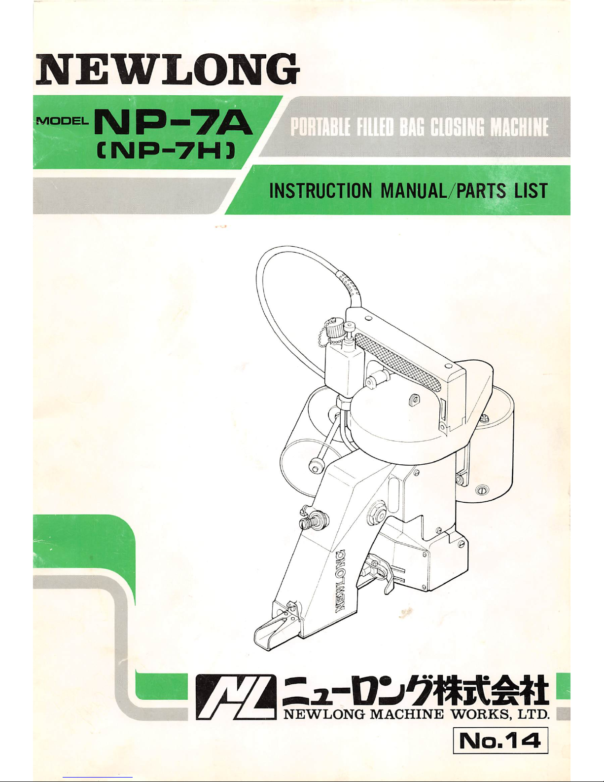
NEWLON6
MODEL
NP-7A
CNP-7H1
PORTABLE
FILLED
BAG
CLOSING
MACHINE
INSTRUCTION
MANUAL/PARTS LIST
NEWLONG
MACHINE
WORKS,
LTD.
No.14
CONTENTS
1.
SPECIFICATIONS
2
2.
PREPARATION
FOR
START
3
1. Oiling 3
2. Needle Setting 3
3. Threading 3
3.
START
4
4.
ADJUSTMENTS
5
1.
Thread
Tension
5
2.
PositionofNeedle
and
Looper
5
3.
PositionofFeed Dog 5
4.
PressureofPresser
Foot
5
5.
REPLACING
PARTS
6
6.
MAINTENANCE
&
LUBRICATION
7
7.
LUBRICATOR
7
1. Operation 7
2.
Maintenance
7
3.
Troubleshooting
8
8.
ORDERING
PARTS
9
NUMERICAL
INDEX
OF
PARTS
26
DIAGRAM
OF SCREW. NUT &
WASHER
28
- 1 -
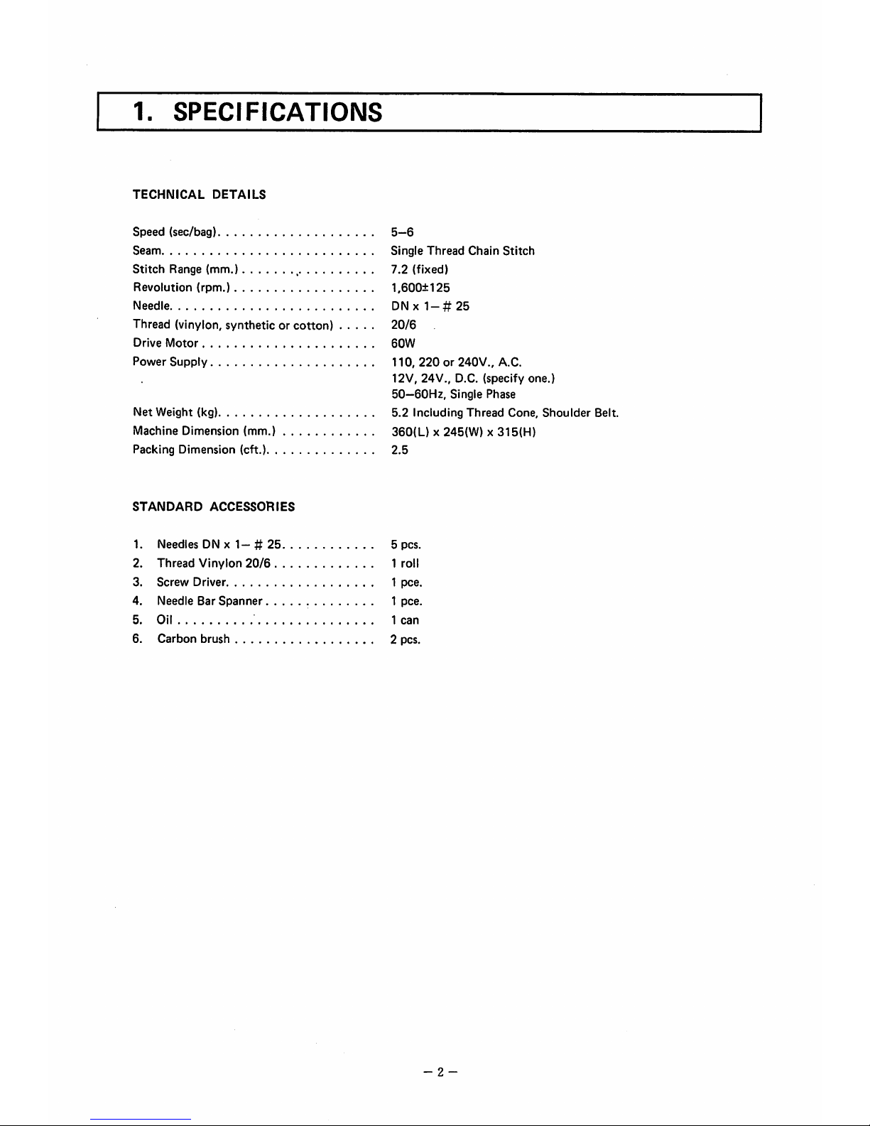
1.
SPECIFICATIONS
TECHNICAL
DETAILS
Speed (sec/bag) 5—6
Seam
Single
Thread
Chain
Stitch
Stitch
Range (mm.) ,
7.2
(fixed)
Revolution
(rpm.)
1,600±125
Needle
DNx1-#25
Thread (vinylon, synthetic or
cotton)
20/6
Drive
Motor
60W
Power
Supply
110,
220
or 240V., A.C.
12V,
24V.,
D.C.
(specify
one.)
50—6OH2,
Single
Phase
Net Weight (kg) 5.2 Including Thread Cone,
Shoulder
Belt.
Machine Dimension (mm.)
360(L)
x 245(W) x 315(H)
Packing Dimension (eft.)
2.5
STANDARD
ACCESSORIES
1.
Needles
DN X
1-#
25
5 pcs.
2.
Thread
Vinylon
20/6
1 roll
3.
Screw
Driver 1
pee.
4.
Needle
Bar
Spanner
1
pee.
5.
Oil
1
can
6.
Carbon
brush 2 pcs.
- 2 -

2.
PREPARATION
FOR
START
1. Oiling (Fig. 1)
Oilingis imperative to keep the machine in good operating
condition. Fill oil in the reservoir (capacity 45 cc). To
feed oil, push the button of the lubricator. One push
feeds 0.08 ccofoil, which would normally service for
several hours
of
operation. Do not run the machine
outofoil, otherwise it will break
down.
2. Needle Setting (Fig. 2,
3,4)
Turn the pulley until Needle Bar reaches its highest
position. Loosen Needle Bar Clamping Nut, and set
Needle in the Bar as deep asit will go.
Be sure to set a Needle with its concave part facing
correctly toward the Looper.
Fbc
Clamping Nut tightly,
otherwise
Needle
may come loose during operation and
break.
3. Threading (Fig. 5)
The machine is delivered being threaded to show you
proper threading
of
the machine, which is shown in
Fig. 5, for identification. Follow the guide numbers
1 to 6ofFig. 5.
® Thread Eyelet
(D Thread Tension Eyelet
(3)
Tension
Disc
@ Thread Eyelet
d)
Needle
Bar
(6) Thread Eyelet
(7) Needle
(D
Tighten
Fig-i y
Loosen
Clannp
Nut
\
Scarf
Fig.4 J
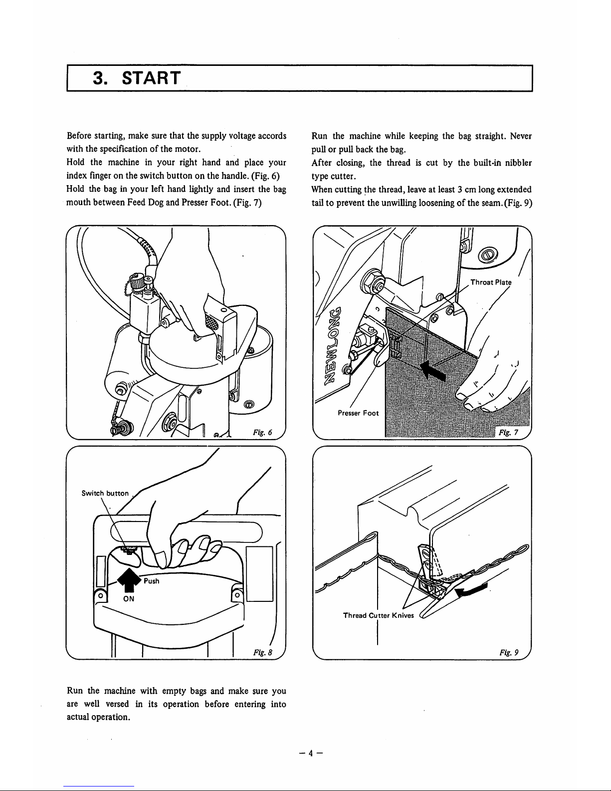
3.
START
Before starting, make sure that the supply voltage accords
with the specification
of
the motor.
Hold the machine in your right hand and place your
index
finger
on the switchbutton on the handle. (Fig. 6)
Hold the bag in your left hand lightly and insert the bag
mouthbetweenFeed
Dog
and
Presser
Foot.(Fig.7)
Fig.
6 J
Switch
button
Run the machine with empty bags and make sure you
are well versed in its operation before entering into
actual operation.
Run the machine while keeping
the
bag straight. Never
pull or pull back the bag.
After closing, the thread is cut by the built-in nibbler
type
cutter.
When cutting the thread, leave at least 3 cm long extended
tail to prevent the unwillinglooseningofthe seam.(Fig. 9)
Throat
Plate
I®
Presser
Foot
Thread
Cutter
Knives
Fig.
9J
- 4 -
4.
ADJUSTMENTS
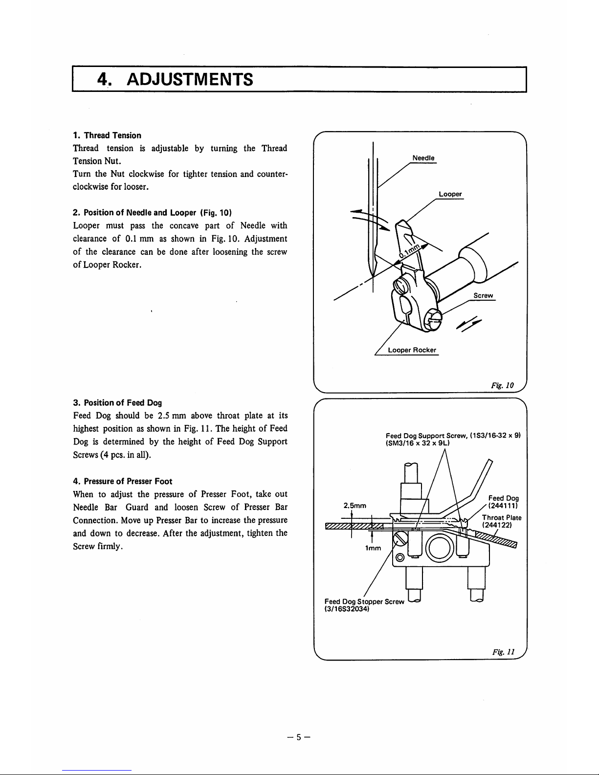
1.
Thread
Tension
Thread tension is adjustable by turning the Thread
Tension
Nut.
Turn the Nut clockwise for tighter tension and counter
clockwise
for
looser.
2. PositionofNeedle
and
Looper (Fig. 10)
Looper must pass the concave part
of
Needle with
clearanceof0.1 mm as shown in Fig. 10. Adjustment
of
the clearance can be done after loosening the screw
of
Looper Rocker.
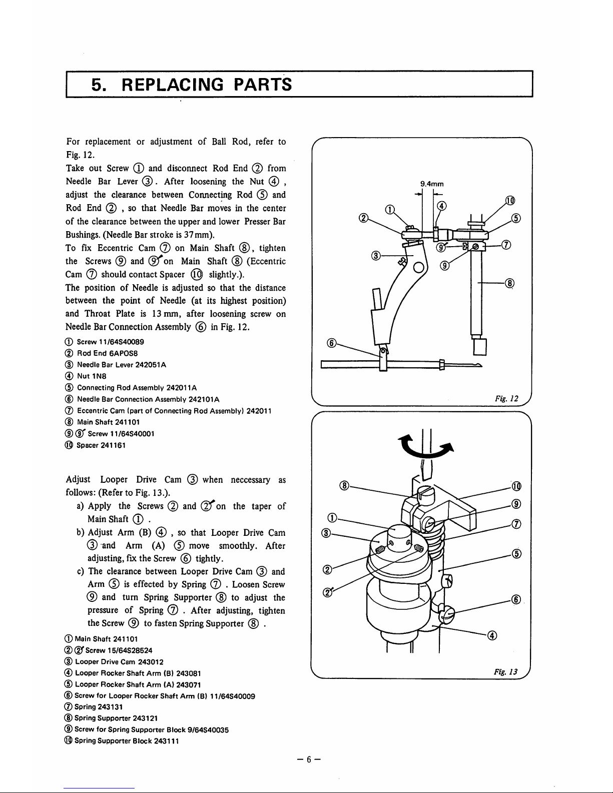
3.
PositionofFeed
Dog
Feed Dog should be 2.5 mm above
throat
plate at its
highest position as shown in Fig. 11. The height of Feed
Dog is determined by the heightofFeed Dog Support
Screws(4 pcs. in all).
4.
PressureofPresser
Foot
When to adjust the pressure of Presser Foot, take out
Needle
Bar
Guard
and
loosen
Screw
of
Presser
Bar
Connection. Move up Presser Bar to increase the pressure
and down to decrease. After the adjustment, tighten the
Screw firmly.
- 5 -
Needle
Looper
Screw
Looper
Rocker
Fig.
10 y
Feed Dog
Support
Screw, (1S3/16-32 x 9)
(SM3/16x32x9L)
2.5mm
Feed
Dog
Stopper
Screw
(3/16S32034)
Feed
Dog
(244111)
Throat
Plate
(244122)
Fig.11J
5.
REPLACING
PARTS
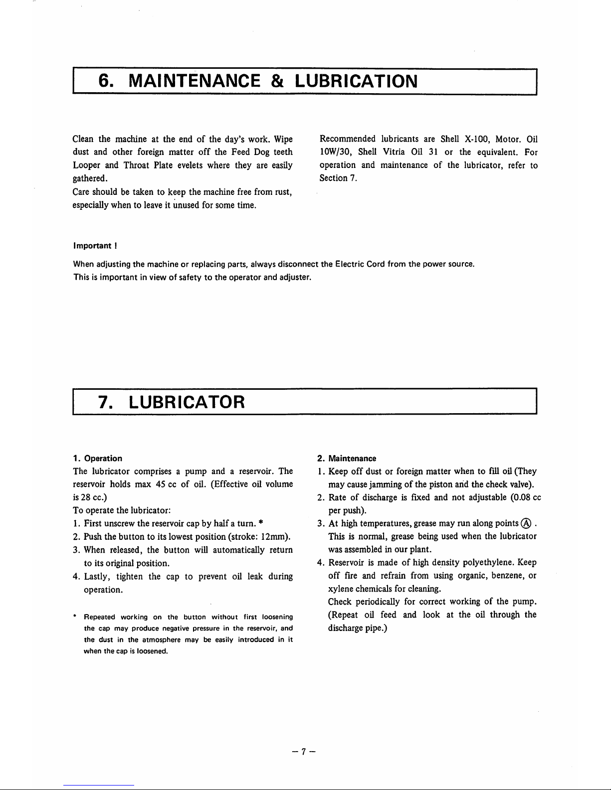
For replacement or adjustmentofBall Rod, refer to
Fig. 12.
Take
out
Screw
(T)
and
disconnect
Rod
End
(2)
from
Needle
Bar
Lever
.
After
loosening
the Nut 0 ,
adjust
the
clearance
between
Connecting
Rod0and
Rod
End
(5) , so that
Needle
Bar
moves
in the
center
of
the clearance between the upper and lower Presser Bar
Bushings.(Needle Bar stroke is 37 mm).
To
fix
Eccentric
Cam
0 on
Main
Shaft
(8),
tighten
the
Screws
(9)
and
on
Main
Shaft
(8)
(Eccentric
Cam0should
contact
Spacer
(0)
slightly.).
The positionofNeedle is adjusted so that the distance
between the point of Needle (at its highest position)
and Throat Plate is 13 mm, after loosening screw on
Needle
Bar
Connection
Assembly
0 in
Fig.
12.
® Screw 11/64S40089
(D Rod End
6APOS8
(D
Needle
Bar
Lever
242051A
® Nut 1N8
(5) Connecting Rod Assembly 242011A
(D
Needle
BarConnection
Assembly
242101A
(7) Eccentric Cam (part of ConnectingRod
Assembly)
242011
(D
Main
Shaft 241101
CD®'
Screw
11/64S40001
O Spacer 241161
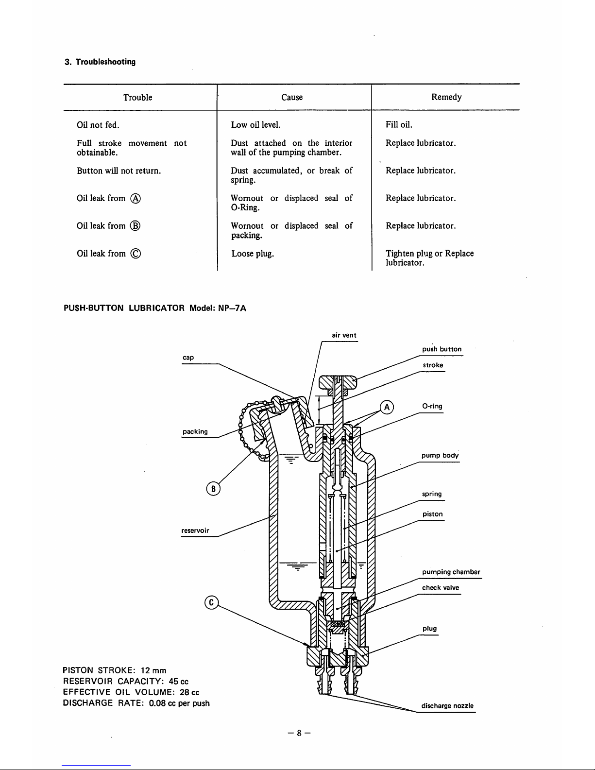
Adjust
Looper
Drive
Cam0when
neccessary
as
follows: (Refer to Fig. 13.).
a)
Apply
the
Screws0andQfon
the
taper
of
Main
Shaft
0 .
b)
Adjust
Arm
(B)
0 ,sothat
Looper
Drive
Cam
0
and
Arm
(A)
0
move
smoothly.
After
adjusting,
fix
the
Screw0tightly.
c)
The
clearance
between
Looper
Drive
Cam0and
Arm0is
effectedbySpring
0 .
Loosen
Screw
0
and
turn
Spring
Supporter
0 to
adjust
the
pressureofSpring
0 .
After
adjusting,
tighten
the
Screw
0 to
fasten
Spring
Supporter
0 .
(D
Main
Shaft 241101
®
(D"
Screw
15/64S28524
® Looper
Drive
Cam243012
® Looper Rocker Shaft Arm (B)243081
® LooperRocker Shaft Arm (A)243071
®
Screw
for
Looper
RockerShaft Arm
(B)
11/64S40009
©Spring 243131
® SpringSupporter 243121
®
Screw
for
Spring
Supporter
Block
9/64S40035
®
Spring
Supporter
Block
243111
(D
(D
m-
- 6 -
(D
(D
9.4mm
(D
Fig.
12 J
U
(0)
(D
(D
CD
Fig.
13 J
6.
MAINTENANCE
&
LUBRICATION
Clean the machine at the endofthe day's work. Wipe
dust and other foreign matter
off
the Feed Dog teeth
Looper and Throat Plate evelets where they are easily
gathered.
Care should be taken to keep the machine free from rust,
especially when to leave it unused for some time.
Recommended lubricants are Shell X-100, Motor. Oil
lOW/30, Shell Vitria Oil 31 or the equivalent. For
operation and maintenanceofthe lubricator, refer to
Section
7.
Important
I
When adjusting
the
machineorreplacing parts, always
disconnect
the
Electric Cord
from
the
power
source.
Thisisimportantinviewofsafetytothe
operator
and
adjuster.
7.
LUBRICATOR
1.
Operation
The lubricator comprises a
pump
and a reservoir. The
reservoir holds max 45 ccofoil. (Effective oil volume
is 28 cc.)
To operate
the
lubricator:
1. First unscrew
the
reservoir capbyhalfaturn.
*
2. Push the button to its lowest position (stroke: 12mm).
3. When released,
the
button
will automatically return
to its original position.
4. Lastly, tighten the cap to prevent oil leak during
operation.
*
Repeated
working
on
the
button
without
first
loosening
the
cap
may
produce
negative
pressureinthe
reservoir,
and
the
dustinthe
atmosphere
maybeeasily
introduced
in it
when
the
capisloosened.
2.
Maintenance
1. Keep
off
dust or foreign matter when to fill oil (They
may cause jammingofthe piston arid the check valve).
2. Rate of discharge is fixed and not adjustable (0.08 cc
per push).
3. At high temperatures, grease may run along points .
This is normal, grease being used when the lubricator
was assembled in our plant.
4. Reservoir is madeofhigh density polyethylene. Keep
off
fire and refrain from using organic, benzene, or
xylene chemicals for cleaning.
Check periodically for correct working of the pump.
(Repeat oil feed and look at the oil through the
discharge pipe.)
7 -
3.
Troubleshooting
Trouble
Cause
Remedy
Oil
not
fed.
Low
oil
level.
FiU
oil.
Full
stroke
movement
not
obtainable.
Dust
attached
on
the
interior
wallofthe pumping chamber.
Replace
lubricator.
Button
will
not
return.
Dust
accumulated,orbreak
of
spring.
Replace lubricator.
Oilleak from (S)
Wornout or displaced seal
of
0-Ring.
Replace lubricator.
Oil
leak
from
(§)
Wornout or displaced seal
of
packing.
Replace lubricator.
Oil
leak
from
© Loose plug. Tighten plug or Replace
lubricator.
PUSH
BUTTON
LUBRICATOR
Model;
NP-7A
packing
reservo
r
PISTON
STROKE:
12
mm
RESERVOIR
CAPACITY:
45
cc
EFFECTIVE
OIL
VOLUME:
28
cc
DISCHARGE
RATE:
0.08ccper
push
air
vent
- 8 -
push
button
stroke
pump
body
spring
piston
pumping
chamber
check
valve
discharge
nozzle
8.
ORDERING
PARTS
The parts list showing all the parts used in the machine is included in this book.
Check the list, and specify parts numbers and quantities required clearly.
Send yourorder to the nearest agent, distributor or one of
our
branch offices.
1. Description of each part and its stamp number is describedin this parts list.
Screws and nuts for parts are shown adjacent to the relevant parts. When ordering parts, describe
clearly
stamp
number
with
its
nameofpart.
2. The parts which have no Ref. Number can not be delivered independently; always order it as an
assembly.
3. A
setofassembled
parts
is represented by
the
stamp
numberofits
main
parts.
4.
The
last figure in
the
parts stamp number advances on each improvementofthe parts.
5.
Part
No.
described
in [ ]ofRemarks
means
old
part
No.
*
The
part
list is
subjecttochange
without
prior
notice.
CONTENTS
(1) THREAD
TENSION
AND COVER PARTS 10
(2)
BUSHINGS,
OILINGS
AND
HANDLE
PARTS 12
(3)
NEEDLE
BAR,
PRESSER
BAR
AND
DRIVING
PARTS
14
(4)
LOOPER
DRIVING
PARTS
16
(5) FEED
DRIVING
AND
THREAD
CUTTER
PARTS
18
(6)
MOTOR
PARTS
(ForTotally
Enclosed
Type
Motor)
20
(7)
SPECIAL
PARTS
FOR NP-7H TYPE 22
(8) CREPE
TAPE
BINDING
AND
CUTTER
PARTS
(Special OrderParts) 24
NUMERICAL
INDEX
OF
PARTS
26
- 9 -

(1)
THREAD TENSION AND COVER PARTS
@
27
28
29
-10-

(1)
THREAD
TENSION
AND
COVER
PARTS
Ref.No.
Part
No.
Description
Q'ty
Remarks
1
245042
Thread
Stand
1
2
15/64S28028
Screw,
for
245042
2
3
1N6
Nut
2
4
3W6
SpringWasher
1
5
2W6
Washer
1
6
KOlOOl
Thread
7
245052
Thread Cone Clamping Rod
1
8
245201
Thread Cone Clamping Nut
1
9
245013
Top Cover
1
10
9/64S40043 Screw, for
245013
11
245261
Thread Eyelet
1
12
11/64S40005
Screw, for 245261
1
13
245071
Thread Tension Eyelet
1
14
245081A
Thread
Tension
Assembly
1
(15-19)
15
245081
Tension
Post
1
16
065261
Tension
Disc
17
245101
Tension Spring
1
18
245091
Tension
Nut
19
9/64S40011
Screw, for
245081A
1
20
245033
Needle
Bar
Guard
1
21
11/64S40005
Screw,
for
245033
1
22
9/64S40065
Screw, for
245033
23
245222
Looper Cover
1
24
9/64S40065
Screw, for
245222
25
245022
Side
Plate
1
26
9/64S40005
Screw, for
245022
27
245481
Gasket
1
28
245302
Inside
Cover
1
29
9/64S40005
Screw, for
245302
4
30
245181
Thread
Cone
Cover
(1)
Special Order
-11-
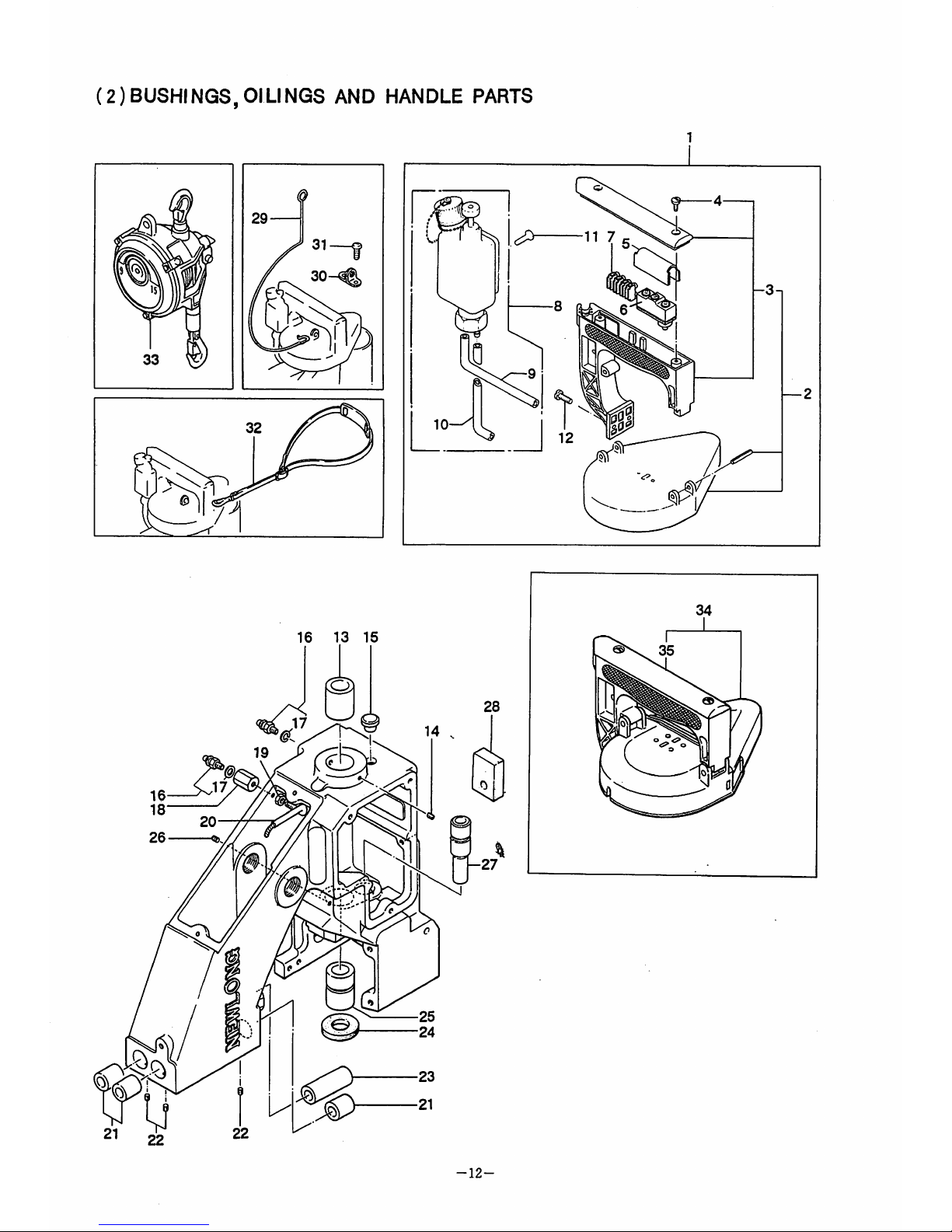
(2)BUSHINGS,01
LINGS
AND
HANDLE
PARTS
16 13
15
-12-

(2)
BUSHINGS,01LINGS
AND
HANDLE
PARTS
Ref.No.
1
2
3
4
5
6
7
8
9
10
11
12
13
14
15
16
17
18
19
20
21
22
23
24
25
26
27
28
29
30
31
32
33
34
35
Part
No.
241024AS
241024A
241024
9/64S40011
245132
C02001
C02006
C05008
D03003
8FU2-6x90F
8FU2-6x60F
685x15
15/64828021
241122
9/64840502
065401
D07021
E03014
245471
1N4
245461
242212
9/64840502
242222
205131
241111
9/64840502
243021
245162
245271
241151
1/8840006
245171
EW-6.5
241024BS
241024B
Description
Handle Assembly
Handle Assembly
Handle
8crew,
for
241024A
Micro
8witch
Cover
Micro8witch (Z-15GK655-B)
Micro
8witch
(X-IOGD-B)
FlexibleTerminalBlock(ML-8K-1,4?)
Oiler
Oil Tube,
with
oil felt
Oil Tube, with oil felt
8crew, for D03003
8crew, for
241024A
Main8haft Bushing,rear
8crew,for241122
Rubber Bushing
Joint
(BN-5-6)
Washer
Joint
Nut
Oil Pipe
Bushing for PresserBar&NeedleBar, upper
8crew,
for
242212
Presser Bar Bushing,lower
Oil
Felt
Main8haft Bushing,rear
8crew, for 241 111
Looper Rocker 8haftBushing
Oil
Felt
Hanger
Hook
8crew, for 241151
8houlder
Belt
^
8pring Balancer
Handle
Assembly
(Safety
type
with pulley
cover)
Handle
Assembly
(Safety
type
with pulley
cover)
-13-
Q'ty
)
(2)
Remarks
(2-11)
(3,4)
(4)
forDCmotor
(9,10)
(17)
-8pecial
Order
(2-11)
(3,4)

Ref.No.
m
Part
No.
241092
3/16S28001
241131
11/64S40502
241161
205131
241101
242011A
242011
3/16S28029
11/64S40001
1N8
Descnption
Synchro
Pulley
Screw, for
241092
Retaining
Collar
Screw,
for
241131
Spacer
Oil
Felt
Main
Shaft
Connecting Rod Assembly
Connecting Rod Sub-Assembly
Screw, for connecting rod cap
Screw, for eccentric
cam
Nut,
for
242011A
Q
ty
Remarks
(9-14)
(10,11)
(3)
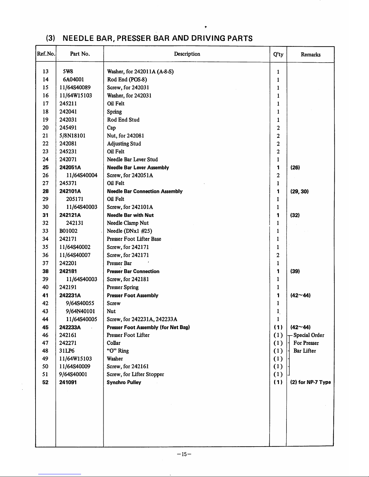
NEEDLE
BAR,
PRESSER
BAR AND
DRIVING
PARTS
Ref.No.
Part
No.
Description
Q'ty
Remarks
13
5W8
Washer,for 242011A (A-8-S)
1
14
6A04001
Rod End (POS-8)
1
15
11/64S40089
Screw, for 242031
1
16
11/64W15103 Washer,
for
242031
1
17
245211
Oil
Felt
1
18
242041
Spring 1
19
242031
Rod
End
Stud
1
20
245491
Cap
2
21
5/8N18101
Nut,
for 242081
2
22
242081
Adjusting
Stud
2
23
245231
GUFelt
2
24
242071
Needle
Bar
Lever
Stud
25
242051A
Needle
Bar
Lever
Assembly
1
(26)
26
11/64S40004 Screw,
for
242051A
27
245371
Oil
Felt
1
28
242101A
Needle
Bar
Connection
Assembly
1
(29,30)
29
205171
Oil
Felt
1
30
11/64S40003 Screw,
for
242101A
1
31
242121A
Needle
Bar
with
Nut
1
(32)
32
242131
Needle Clamp Nut 1
33
B01002
Needle (DNxl #25) 1
34
242171
Presser
Foot
Lifter
Base
35
11/64S40002 Screw, for 242171 1
36
11/64S40007 Screw, for 242171
37
242201
Presser
Bar
1
38
242181
Presser
Bar
Connection
1
(39)
39
11/64S40003 Screw,
for
242181
1
40
242191
Presser Spring 1
41
242231A
Presser
Foot
Assembly
1
(42-44)
42
9/64S40055
Screw
1
43
9/64N40101
Nut
1
44
11/64S40005 Screw, for 242231A,
242233A
1
45
242233A
Presser
Foot
Assembly (for
Net
Bag)
(1)
(42-44)
46
242161
Presser
Foot
Lifter
(1)
p
Special
Order
47
242271
Collar
(1)
•
For
Presser
48
31LP6
"0"
Ring
(1)
•
Bar
Lifter
49
11/64W15103
Washer
(1)
-
50
11/64S40009
Screw, for 242161
(1)
-
51
9/64S40001 Screw, for Lifter Stopper
(1)
52
241091
Synchro
Pulley
(1)
(2)
for
NP-7
Type
-15-
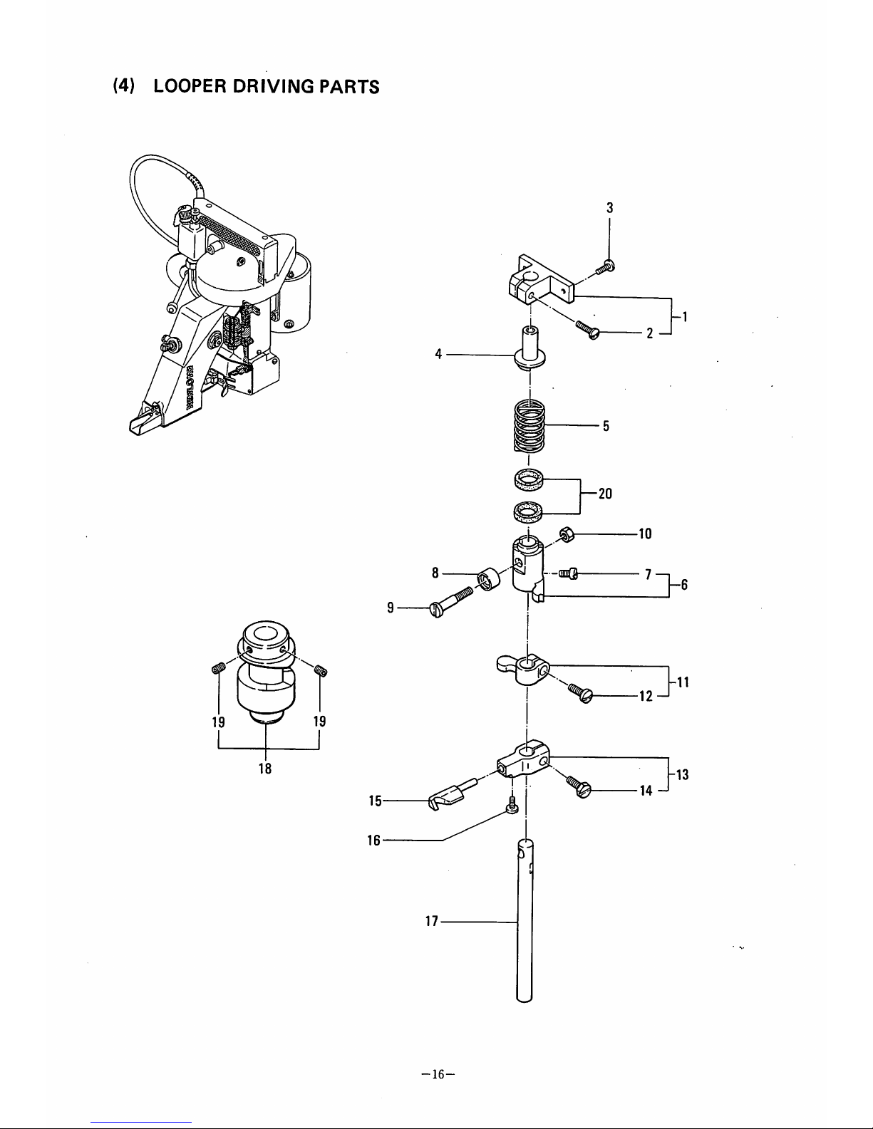
(4)
LOOPER
DRIVING
PARTS
17
-16-

(4)
LOOPER DRIVING PARTS
Ref.No,
4-1
2
3
4
5
6
7
8
9
10
11
12
13
14
15
16
17
18
19
20
Part
No.
243111
9/64S40035
9/64S40005
243121
243131
243071
11/64S40002
243041
243061
11/64N40201
243081
11/64S40009
243092
11/64S40089
243102
9/64S40001
243032
243012
15/64S28524
205131
Description
Spring
Supporter
Block
Screw, for 243111
Screw, for 243111
Spring
Supporter
Spring
Looper
Rocker
Shaft
Arm
(A)
Screw,
for
243071
Roller
Roller
Stud
Screw
Nut,
for 243061
Looper
Rocker
Shaft
Arm
(B)
Screw, for 243081
Looper
Rocker
Screw, for
243092
Looper
Screw, for
243102
Looper Rocker Shaft
Looper
Drive
Cam
Screw,
for
243012
Oil
Felt
-17-
Q'ty
Remarks
(2)
(7)
(12)
(14)
(19)

(5)
FEED
DRIVING
AND
THREAD
CUTTER
PARTS
31 ^
30
-18-

(5)
FEED
DRIVING
AND
THREAD
CUTTER
PARTS
Ref.No.
Part
No.
Description
Q'ty
Remarks
5-1
244011A
Feed
Dog
Carrier
Block
Assembly
1
(2,3)
2 183/16-32x9
Feed Dog8upport8crew (8M3/16x32x9)
4
3
245391
Oa
felt
1
4
244102
81ide
Block
Guide
8tud
1
5
9/64S40011 8crew, for
244102
2
6
246011
Knife
Bracket
Extension
1
7
3/16S32031 8crew, for 246011 2
8
244111
Feed Dog
1
9
3/16S32034 8crew, for 244111
1
10
244081
81ide
BlockAdjusting
1
11
3/16S32025 Lock Bolt, for 244091
2
12
11/64W15103
Washer, for 244091
2
13
244091
8tud
8Ude Block Adjusting 8upport
2
14
3/8N24201 .
Lock
Nut,
for 244091
2
15
244122
Throat
Plate
1
16
9/64S40043 8crew, for
244122
3
17
246081
BaU
1
18
lB3xl2
Bolt, for 246081 (M3x0.5xl2 2)
1
19
1N3
Nut, for 246081 (M3x0.5)
1
20
1W3
Washer,for 246081 (M3)
1
21
11/64840049
8crew, for 246021
1
22
11/64W15103 Washer, for 246021
1
23
246021
Kiufe
Bracket
1
24
246032
Knife
Bracket
Pin
1
25
246042
Bushing,for 246032
1
26
246051
Knife Tension 8pring
1
27
9/64840502
8crew, for
246042
1
28
246061
Knife Moving
1
29
1/8840003 8crew, for 246061
30
246071
Knife 8tationary
1
31
1/8840003
8crev/, for 246071
32
3W3
8pring Lock
Washer
(M3)
1
-19-
I
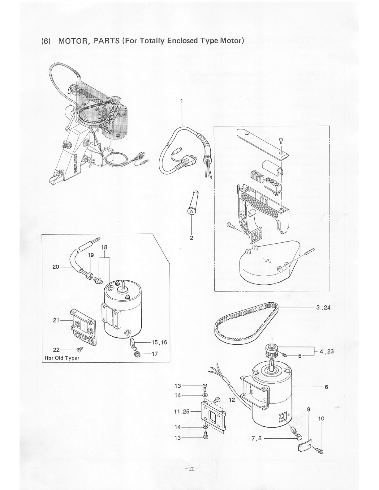
11,25

(6) MOTOR, PARTS (For Totally Enclosed Type Motor)
Ref.No
Part
No.
C04001
C04003
C04004
C04005
C04006
C04007
C04009
211151
FOlOOl
241083
11/64S40504
COlOlO
COlOll
C01012
C01013
C01014
7
C08004
8
C08005
9
C07003
10
4S3x6-W
11
241073
12
15/64S28021
13
11/64S40075
14
11/64W10101
15
C08001
16
C08003
17
C07001
18
245321
19
245501
20
245361
21
241062
22
FC103238
23
24
F01002
25
241072
Description
Cabtyer Cord, with Plug (Standard Type)
Cabtyer Cord, with Plug (American Type)
Cabtyer Cord, with Plug(British TVpe)
Cabtyer Cord, with Plug(German Type)
Cabtyer Cord,with Plug(French Type)
Cabtyer Cord, with Plug(Australian Type)
Cabtyer Cord, with Plug(for DCMotor)
Rubber Bushing(for C04003-C04007)
Timing Belt
Motor
Pulley
Screw, for
241083
UniversalMotor (1lOV)
Universal Motor (220V)
Universal Motor (240V)
UniversalMotor (24V)
UniversalMotor (12V)
Carbon Brush,for ACMotor (size 6x 8x 15)
Carbon Brush,for DC Motor (size 6x 8x 15)
Cap
Screw (with washer)
Motor
Base
B
Screw, for
241073
Screw, for Motor
Washer, for Motor
Carbon Brush,for ACMotor (size 5x8x 14)
Carbon Brush,for DC Motor (size 5x 8x 14)
Cap
Connector
B
Nut
Cord
Cover
Motor
Base
A
Screw, for
241062
Motor
Pulley
(for
Old
type)
Timing Belt (for Old type)
Motor
Base
B
-21-
Q'ty
2
2
2
2
1
4
4
4
(2)
(2)
(2)
(1)
(1)
(1)
(1)
(4)
(1)
(1)
(1)
Remarks
(5)
(7,9,10)
(7,9,10)
(7,9,10)
(8~10)
(8-10)
-r
for
Old
Part
(5)
for NP-7Type
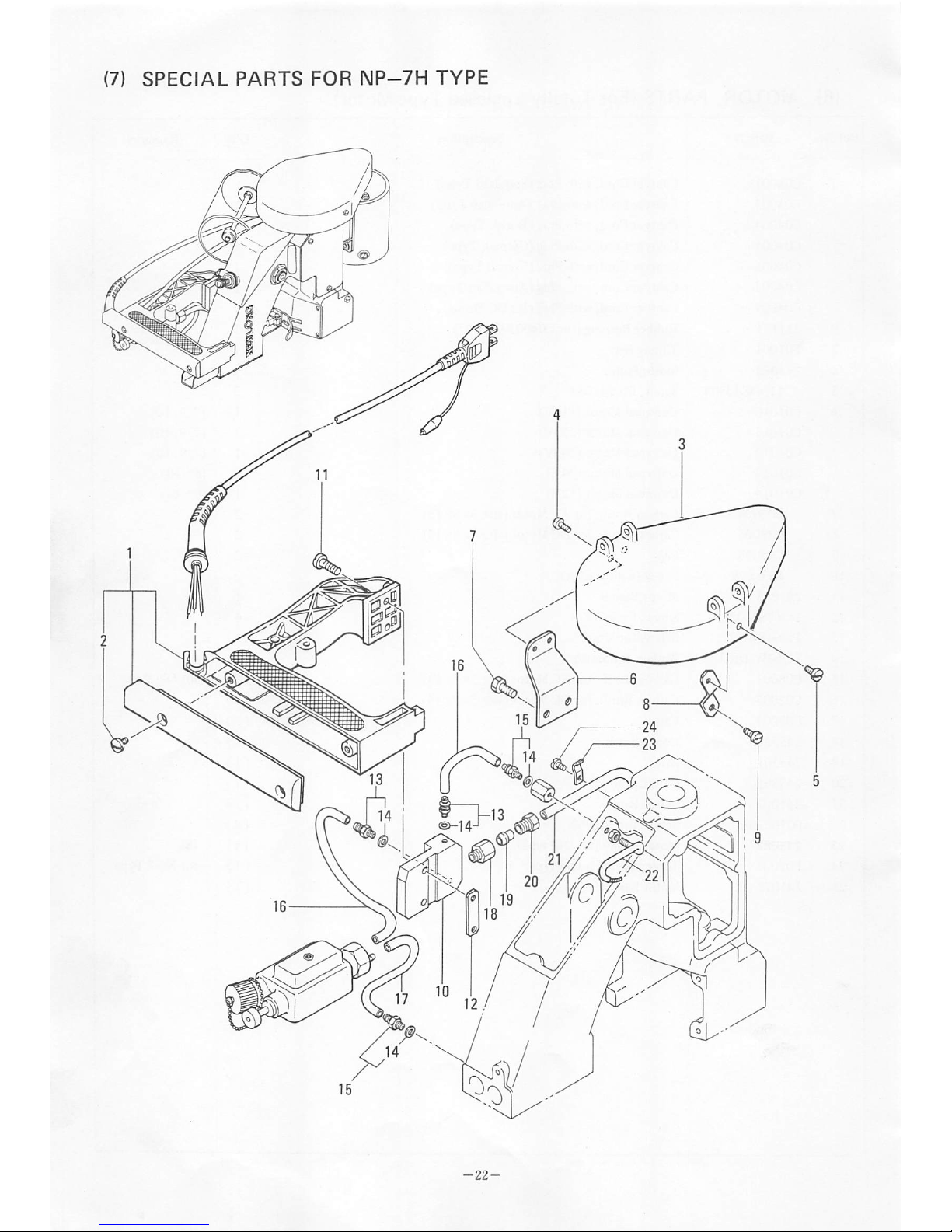

(7)
SPECIAL
PARTS
FOR
NP-7H
TYPE
Ref.No
7-1
2
3
4
5
6
7
8
9
10
11
12
13
14
15
16
17
18
19
20
21
22
23
24
Part
No.
241024
9/64S40011
241212
9/64S40004
9/64S40052
241242
15/64S28004
241231
9/64S40005
241223
15/64S28032
241253
D07021
E03014
D07021
8FU2-6x95F
8FU2-6x70F
D07022
D07023
D07024
8FN24xl35F
245462
D07009
9/64S40005
Description
Handle
Screw
Pulley Cover
Screw, for
241053
Screw, for
241053
Pulley Cover Holder A
Screw, for
241242
Pulley Cover Holder B
Screw,
for
241231
Handle
Base
Screw, for
241253
Handle
Base
Holder
Joint
(BN-5-6)
Washer
Joint
(BN-5-6)
OilTube (06x95 fi),with oil felt
Oil Tube (06x70 £), with oil felt
Joint
Compression Sleeve
Compression Bushing
OilTube (06x135
fi),
with oilfelt
Oil Pipe
Tube
CUp
(PC4-1)
Screw,
for
D07009
•23-
Q'ty
1
2
1
2
1
1
2
1
1
1
2
1
2
4
2
2
Remarks
(2)
(14)
(14)

(8) CREPE TAPE
BINDING
AND CUTTER PARTS (Special Order Parts)
11,37
13,38
17,39
-24-

(8) CREPE TAPE BINDING AND CUTTER PARTS (Special Order Parts)
Ref.No.
Part
No.
Description
Q'ty
Remarks
8-1
247071
Crepe Tape Bracket
1
2
247091
Crepe Tape Hanger Stud
1
3
9/64S40035 Screw, for 247071
4
1N6
Nut, for 247091 (M6) 1
5
2W6
Washer,
for 247091 (M6) 1
6
247081
Crepe Tape Supporter 1
7
11/64S40015 Screw, for 247071 1
8
1/4W03205 SpringWasher,for 247071 1
9
1/4W15105
Washer, for 247071
1
10
11/64N40203 Nut,
for
247071 1
11
244132
Throat
Plate
1
12
9/64S40043
Screw, for
244132
3
13
247051
Holder, for crepe tape binder 1
14
9/64S40043
Screw, for 247051
2
15
9/64N40101
Nut, for 247051
2
16
2W4
Washer,for 247051 (M4)
2
17
247061
Crepe Tape binder 1
18
9/64S40054 Screw, for 247061 2
19
2W4
Washer,
for 247061 (M4)
2
20
247031
Cutter
Lever
1
21
11/64S40046 Screw, for 247011 2
22
11/64W10101 Washer, for 247011 2
23
247041
Screw, for 247031
1
24
15/64N28206
Nut,
for 247021 2
25
3W6
SpringLock
Washer,
for 247021, (M6) 2
26
2W6
Washer,
for 247021, (M6)
2
27
11/64S40029
Stopper Screw, for 247011
1
28
3/16S32026
Stopper Screw, for 247031
1
29
247021
Hinge Pin
1
30
247011
Knife, Moving
1
31
247001
Knife, Stationary 1
32
1/8S40003 Screw, for 247001
33
183261
Spring
Hook
1
34
247073
Crepe Tape Bracket
(1)
pfor
Crepe
35
247092
Crepe Tape HangerStud
(1)
-
Tape width
36
247082
Crepe Tape Supporter
(1)
-
70
mm
37
244133
Throat
Plate
(1)
•
38
247052
Holder, for crepe tape binder
(1)
-
39
247063
Crepe tape Binder
(1)
-
40
242261A
Presser
Foot
Assembly
(1)
-25-

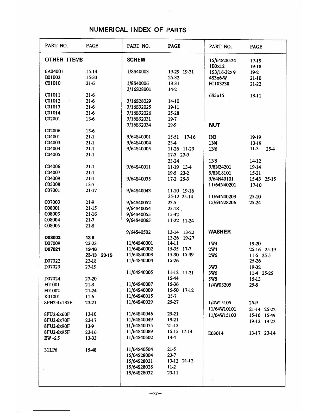
NUMERICAL
INDEX
OF
PARTS
PART
NO.
PAGE
PART
NO.
PAGE
PART
NO.
PAGE
065261
11-16
242212
13-21
245271
13-29
065401
13-15
242222
13-23
245302
11-28
183261
25-33
242231A
15-41
245321
21-18
205131
13-24
14-6
242233A
15-45
245361
21-20
17-20
242261A
25-40
245371
15-27
205171
15-29
242271
1547
2453^1
19-3
211151
21-2
243012
17-18
245461
13-20
243021
13-27
245462
23-22
241024
13-3
23-1
243032
17-17
245471
13-18
241024A
13-2
243041
17-8
245481
11-27
241024AS
13-1
243061
17-9
245491
15-20
241024B
13-35
243071
17-8
245501
21-19
241024BS
13-34
243081
17-11
246011
19-6
241062
21-21
243092
17-13
246021
19-23
241072
21-25
243102
17-15
246032
19-24
241073
21-11
243111
17-1
246042
19-25
241082
21-23
243121
174
246051
19-26
241083
21-4
243131
17-5
246061
19-28
241091
15-52
244011A
19-1
246071
19-30
241092
14-1
244081
19-10
246081
19-17
241101
14-7
244091
19-13
247001
25-31
241111
13-25
244102
194
247011
25-30
241122
13-13
244111
19-8
247021
25-29
241131
14-3
244122
19-15
247031
25-20
241151
13-30
244132
25-11
247041
25-23
241161
14-5
244133
25-37
247051
25-13
241212
23-3
245013
11-9
247052
25-38
241223
23-10
245022
11-25
247061
25-17
241231
23-8
245033
11-20
247063
25-39
241242
23-6
245042
11-1
247071
25-1
241253
23-12
245052
11-7
247073
25-34
242011
14-9
245071
11-13
247081
25-6
242011A
14-8
245081A
11-14
247082
25-36
242031
15-19
245081
11-15
247091
25-2
242041
15-18
245091
11-18
247092
25-35
242051A
15-25
245101
11-17
242071
15-24
245132
13-5
242081
15-22
245162
13-28
242101A
15-28
245171
13-32
242121A
15-31
245181
11-30
242131
15-32
245201
11-8
242161
1546
245211
15-17
242171
15-34
245222
11-23
242181
15-38
245231
15-23
242191
1540
245261
11-11
242201
15-37
-26-
NUMERICAL
INDEX
OF
PARTS
PART
NO.
PAGE
PART
NO.
PAGE
PART
NO.
PAGE
OTHER
ITEMS
SCREW
15/64828524
17-19
lB3xl2
19-18
6A04001
15-14
1/8S40003
19-29
19-31
183/16-32x9
19-2
B01002
15-33
25-32
483x6-W
21-10
COlOlO
21-6
1/8S40006
13-31
FC103238
21-22
3/16S28001
14-2
COlOll
21-6
685x15
13-11
C01012
21-6
3/16S28029
14-10
C01013
21-6
3/16S32025
19-11
C01014
21-6
3/16S32026
25-28
C02001
13-6
3/16S32031
19-7
3/16S32034
19-9
NUT
C02006
13-6
C04001
21-1
9/64S40001
15-51
17-16
IN3
19-19
C04003
21-1
9/64S40004
234
1N4
13-19
C04004
21-1
9/64S40005
11-26
11-29
1N6
11-3
254
C04005
21-1
17-3
23-9
23-24
1N8
14-12
C04006
21-1
9/64S40011
11-19
134
3/8N24201
19-14
C04007
21-1
19-5
23-2
5/8N18101
15-21
C04009
21-1
9/64S40035
17-2
25-3
9/64N40101
154325-15
C05008
13-7
11/64N40201
17-10
C07001
21-17
9/64S40043
11-10
19-16
25-12
25-14
11/64N40203
25-10
C07003
21-9
9/64S40052
23-5
15/64N28206
25-24
C08001
21-15
9/64S40054
25-18
C08003
21-16
9/64S40055
1542
C08004
21-7
9/64S40065
11-22
11-24
C08005
21-8
9/64S40502
13-14
13-22
WASHER
D03003
13-8
13-26
19-27
D07009
23-23
11/64S40001
14-11
1W3
19-20
D07021
13-16
11/64S40002
15-35
17-7
2W4
25-16
25-19
23-13
23-15
11/64S40003
15-30
15-39
2W6
11-5
25-5
D07022
23-18
11/64S40004
15-26
25-26
D07023
23-19
3W3
19-32
11/64S40005
11-12
11-21
3W6
114
25-25
D07024
23-20
1544
5W8
15-13
FOlOOl
21-3
11/64S40007
15-36
1/4W03205
25-8
F01002
21-24
11/64S4C009
15-50
17-12
KOlOOl
11-6
11/64S40015
25-7
8FN24xl35F
23-21
11/64S40029
25-27
1/4W15105
25-9
11/64W10101
21-14
25-22
8FU2-6x60F
13-10
11/64S40046
25-21
11/64W15103
15-16
1549
8FU2-6x70F
23-17
11/64840049
19-21
19-12 19-22
8FU2-6x90F
13-9
11/64840075
21-13
8FU2-6X95F
23-16
11/64840089
15-15
17-14
E03014
13-17
23-14
EW-6.5
13-33
11/64840502
144
31LP6
1548
11/64840504
21-5
15/64828004
23-7
15/64828021
13-12
21-12
15/64828028
11-2
15/64828032
23-11
-27-

NP-7A
SCREW.
NUT &
WASHER
i-'y
h,
9'yv-V-
FULL
SIZE
(IS-^)
9/64840502
11/64840502 11/64340504
15/64828524
1/8840006
9/64840001
9/64840004
9/64840052
9/64840054
9/64840011
9/64840065
9/64840005
9/64840035
11/64840029
11/64840001
11/64840002
11/64840009
11/64840046
11/64840003
11/64840004
11/64840005
3/16832031
15/64828004
15/64828021
15/64828032
1/8840003
9/64840043
11/64840007
15/64828028
11/64840015
3/16828001
3/16832026
3/16828029
3/16832034
9/64840055
11/64840049
11/64840075
11/64840089
3/16832025
183x12
183/16-32x9
483x6-W
FC103238
685x15
9/64N40101
11/64N40201
11/64N40203
15/64N28206
3/8N24201
5/8N18101
1N3
1N4
1N6
1N8
11/64W10101
11/64W15103
1/4W03205 1/4W15105
1W3
2W4 2W6
3W3
3W6
5W8
E03014
: m
Si5
^ m E ^ ±
'110
6-4-14
TEL03-3843-73ll(H3
TLX
265-5306
FAX
03-3843-9998
I -
14-14
IEL03-3843-0269
III
TLX265-53C6
FAX03-3843-0260
Ai
Jlj^HIm7kOj5
Ife
4 T i TELOl66-47-3267
T078-02
FAXO 166 - 48 - 1654
H ^
5?lrfi:;*:?llfBa?S?Bai23
TEL0I77-66-269I
t030
FAXO
177-66-7082
iff M ^ jg m titOjai I
-109-5
TEL025-275-I45I
T950
FAX025-273-8488
SI5UJ|i?UjrfTM:^3-3-7
TEL0249-34-3I77
X963
FAX0249-32-7076
^ ^ ^ ^
rti
HI
ffl
fflj
280
- 3 TEL0282-23-398I
X328-0I
FAX0282-23-3809
m a 1
TEL0299-36-4612
X3I4-02
FAX0299-96-7359
.1
P.li^feMl^^Bl:^$±)gi;k490-l
TEL0270-65-0883
t370-
11
FAX0270
- 65 -
0889
M:
1?
TEL0268-64-269I
=f389-03
FAX0268-64-26I9
m I
-10-30
TEL0775-53-269I
X520-30
FAX0775-53-7846
a a m PI PE :1b fill 9 - 2
TEL0794-47-2570
X676-0I
FAX0794-47-2807
'J^ ?|5
lJjPm:^?:>iei§^;^J^3640-
I
TEL0839-89-269I
X754
FAX0839-89-4999
I - II - 10
TEL0992-68-3235
T89I-0I
FAX0992-67-6023
i\h
m
W W m Mil2 - 17 - 2
T047-02
^
flll^m^^^ESl-S3
-14-10
t982
« 4 - 3 - 17
TI20
m m m M JK s
-12-
2
t280
^j^mtSmETcl-
I
-17-3
t230
>9 tK ;t5 tk m
t424
5 0 3
«SMr!)4'JIIEW^BII3-
5
T454
S Oj
®UjmTMgl-l-36
t93I
± B5
:'^B5m7iJiE±Fj3
2 - I - 8
t553
IS) UJ
1844-5
T703
tS
til
15tllrtT>I^EBj
1460-4
T762
m &
/Aam4'Ei?iA0j7-28
X733
7i
151
7i!S9m?fiMSl??0fHBlT/Jt487
T8II-0I
IE
LO134-62-2691
(ffi
FAXO134-62-2682
TEL022-286-5I89
FAX022-286-8230
TEL03-3629-269l(Ha
FAX03-3629-2695
TEL0472-63-I542
FAX0472-66-6546
TEL045-584-269l(ft)
FAX045-584-9450
TEL0543-64-269l(ft)
FAX0543-65-2533
TEL052-35l-269l(ft)
FAX052-363-369I
TEL0764-4I
-2690
FAX0764-3I
-2691
TEL
06-462-435lira
FAX
06-465-5926
TEL0862-77-6527
FAX0862-77-6528
TEL0877-46-3659(fia
FAX0877-46-3662
TEL082-293-269l(ft)
FAX082-295-65I6
TEL092-962-4006(ft)
FAX092-963-0249
^ 4 - 8 - 14
TI25
+ 9 - I
=f277
m I5|
1S:t^lT«i5ag|?SI5|fflI0l5|4254
X349-I3
T0I8-57
± m
±>im4'4TBT
1322
t300
a
if
=f382
4 0 1
1-6
TEL03-3603-225l(m
FAX03-3603-9648
TEL047I
-33-2691
FAX047I
-33-2695
TEL0282-62-320l«t)
FAX0282-62-5400
TELO186-49-5201
FAXO
186-49-0759
TEL0298-4l-0805(f«
FAX0298-42-9I05
TEL0262-45-7223
FAX0262-48-0847
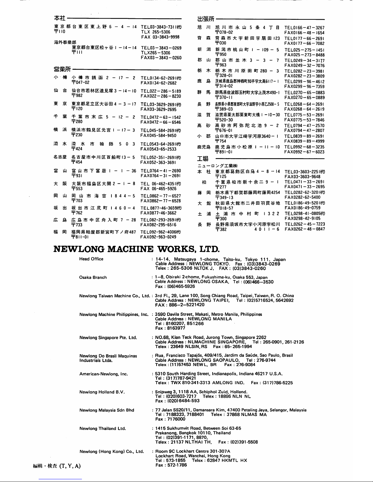
NEWLONG
MACHINE
WORKS.
LTD.
Head
Office
Osaka
Branch
Newlong
Taiwan
Machine
Co..
Ltd.
Newlong
Machine
Philippines,
Inc.
Newlong
Singapore
Pte.
Ltd.
Newlong
Do Brasil
Maquinas
Industrials
Ltda.
American-Newlong.
Inc.
Newlong
Holland
B.V.
Newlong
Malaysia
Sdn
Bhd
Newlong
Thailand
Ltd.
Newlong
(Hong
Kong)
Co..
Ltd.
t3^(T,Y,A)
14-14,
Matsugaya
1-chome,
Taito-ku, Tokyo
111,
Japan
Cable
Address
: NEWLONG TOKYO. Fax :
(03)3843-0269
Telex :
265-5306
NLTOKJ,FAX :
(03)3843-0260
1—8,Obiraki 2-chome, Fukushima-ku, Osaka
553,
Japan
Cable
Address
: NEWLONG
OSAKA,
Tel :
(06)466-3530
Fax:(06)465-5926
3rd
Fl.,
29,
Lane
100,
Song
Chiang
Road,
Taipei,Taiwan,
R. O. China
Cable
Address;NEWLONG
TAIPEI.
Tel :
(02)5716524,
5642692
FAX:886-2-5221420
3590
Davila
Street.
Makati.
Metro
Manila.
Philippines
Cable
Address:NEWLONG
MANILA
Tel:8160207.
851266
Fax:8163977
N0.68,
Kian
Teck
Road.
Jurong
Town.
Singapore
2262
Cable
Address:NLMACHINE
SINGAPORE.
Tel :
265-0901.
261
-2126
Telex:23649
NLSIN.
RS
Fax:65-265-1994
Rua.
Francisco
Tapaj6s.
409/415.
JardimdaSaude,
Sao
Paulo.
Brasil
Cable
Address:NEWLONG
SAOPAULO,
Tel :
276-9744
Telex:(11)57453
NEWL.
BR
Fax:276-9084
5310
South
Harding
Street.
Indianapolis,
Indiana
46217
U.S.A.
Tel:(317)787-9421
Telex:TWX
810-341-3313
AMLONG
IND.
Fax:(317)786-5225
Snipweg3,1118
AA.
Schiphol
Zuid,
Holland.
Tel:(020)603-7217
Telex:18896
NLN
NL
Fax:(020)6484-593
77
Jalan
SS20/11,
Damansara Kim,
47400
Petaling
Jaya,
Selangor,
Malaysia
Tel:7188323.
7188401
Telex:37868
NLMAS
MA
Fax:7176000
1415
Sukhumvit
Road.
Between
Soi
63-65
Prakanong.
Bangkok
10110.
Thailand
Tel:(02)391-1171.8870.
Telex:21137
NLTHAI
TH,
Fax:(02)391-5508
Room9CLockhart
Centre
301
-307A
Lockhart
Road.
Wanchai.
Hong
Kong
Tel:573-1855
Telex:62847
HKMTL
HX
Fax:572-1786

HA
14-14
MATSUGAYA
1-CHOME, TAITO-KU TOKYO, JAPAN TEL:
(3843)
0269
No.14
NO.IE3007H
92-03-1000F
PRINTEDINJAPAN
1985,
1991
NEWLONG
MACHINE
WORKS,
LTD.
 Loading...