

Newlong NP-7A User Manual
NEWLON6
MODEL
NP-7A
CNP-7H1
PORTABLE
INSTRUCTION
FILLED
BAG
MANUAL/PARTS LIST
CLOSING
MACHINE
NEWLONG
MACHINE
WORKS,
No.14
LTD.
CONTENTS
1.
SPECIFICATIONS
2.
PREPARATION
1. Oiling 3
2. Needle Setting 3
3. Threading 3
3.
START
4.
ADJUSTMENTS
1.
Thread
2.
PositionofNeedle
Tension
FOR
and
START
Looper
2
3
4
5
5
5
3.
PositionofFeed Dog 5
4.
5.
REPLACING
6.
MAINTENANCE
7.
LUBRICATOR
PressureofPresser
PARTS
&
Foot
LUBRICATION
1. Operation 7
2.
Maintenance
3.
Troubleshooting
8.
ORDERING
NUMERICAL
DIAGRAM
PARTS
INDEX
OF
OF SCREW. NUT &
PARTS
WASHER
5
6
7
7
7
8
9
26
28
- 1 -
1.
SPECIFICATIONS
TECHNICAL
DETAILS
Speed (sec/bag) 5—6
Seam
Stitch
Range (mm.) ,
Revolution
Needle
(rpm.)
Thread (vinylon, synthetic or
Drive
Motor
Power
Supply
cotton)
Single
Thread
7.2
(fixed)
1,600±125
DNx1-#25
20/6
60W
110,
220
12V,
24V.,
50—6OH2,
Chain
Stitch
or 240V., A.C.
D.C.
(specify
Single
Phase
Net Weight (kg) 5.2 Including Thread Cone,
Machine Dimension (mm.)
Packing Dimension (eft.)
STANDARD
1.
Needles
2.
Thread
3.
Screw
4.
Needle
5.
Oil
6.
Carbon
ACCESSORIES
DN X
1-#
Vinylon
Driver 1
Bar
20/6
Spanner
brush 2 pcs.
25
360(L)
2.5
5 pcs.
1 roll
pee.
1
pee.
1
can
x 245(W) x 315(H)
one.)
Shoulder
Belt.
- 2 -
2.
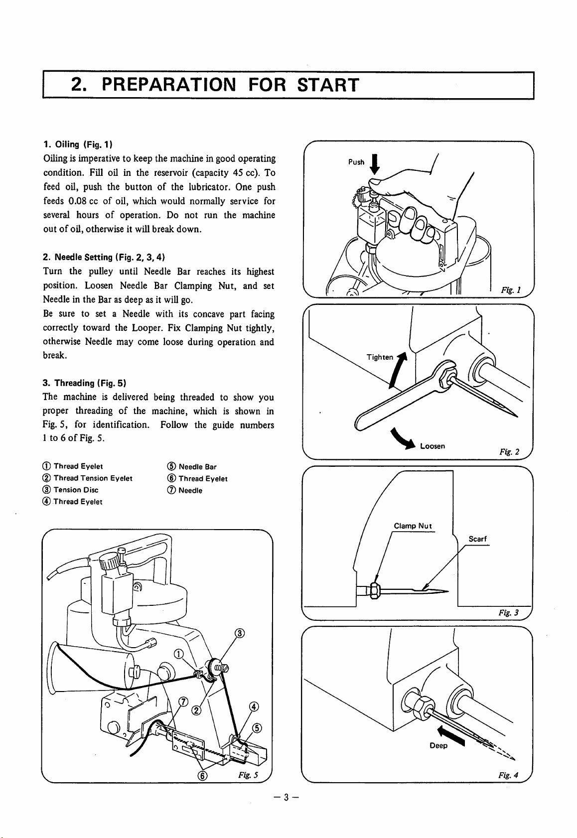
1. Oiling (Fig. 1)
PREPARATION
FOR
Oilingis imperative to keep the machine in good operating
condition. Fill oil in the reservoir (capacity 45 cc). To
feed oil, push the button of the lubricator. One push
feeds 0.08 ccofoil, which would normally service for
several hours
outofoil, otherwise it will break
of
operation. Do not run the machine
down.
START
2. Needle Setting (Fig. 2,
3,4)
Turn the pulley until Needle Bar reaches its highest
position. Loosen Needle Bar Clamping Nut, and set
Needle in the Bar as deep asit will go.
Be sure to set a Needle with its concave part facing
correctly toward the Looper.
otherwise
break.
3. Threading (Fig. 5)
Needle
may come loose during operation and
Fbc
Clamping Nut tightly,
The machine is delivered being threaded to show you
proper threading
of
the machine, which is shown in
Fig. 5, for identification. Follow the guide numbers
1 to 6ofFig. 5.
® Thread Eyelet
(D Thread Tension Eyelet
(3)
Tension
@ Thread Eyelet
Disc
d)
Needle
Bar
(6) Thread Eyelet
(7) Needle
Tighten
Clannp
Loosen
Nut
Fig-i y
\
Scarf
(D
Fig.4 J
3.
START
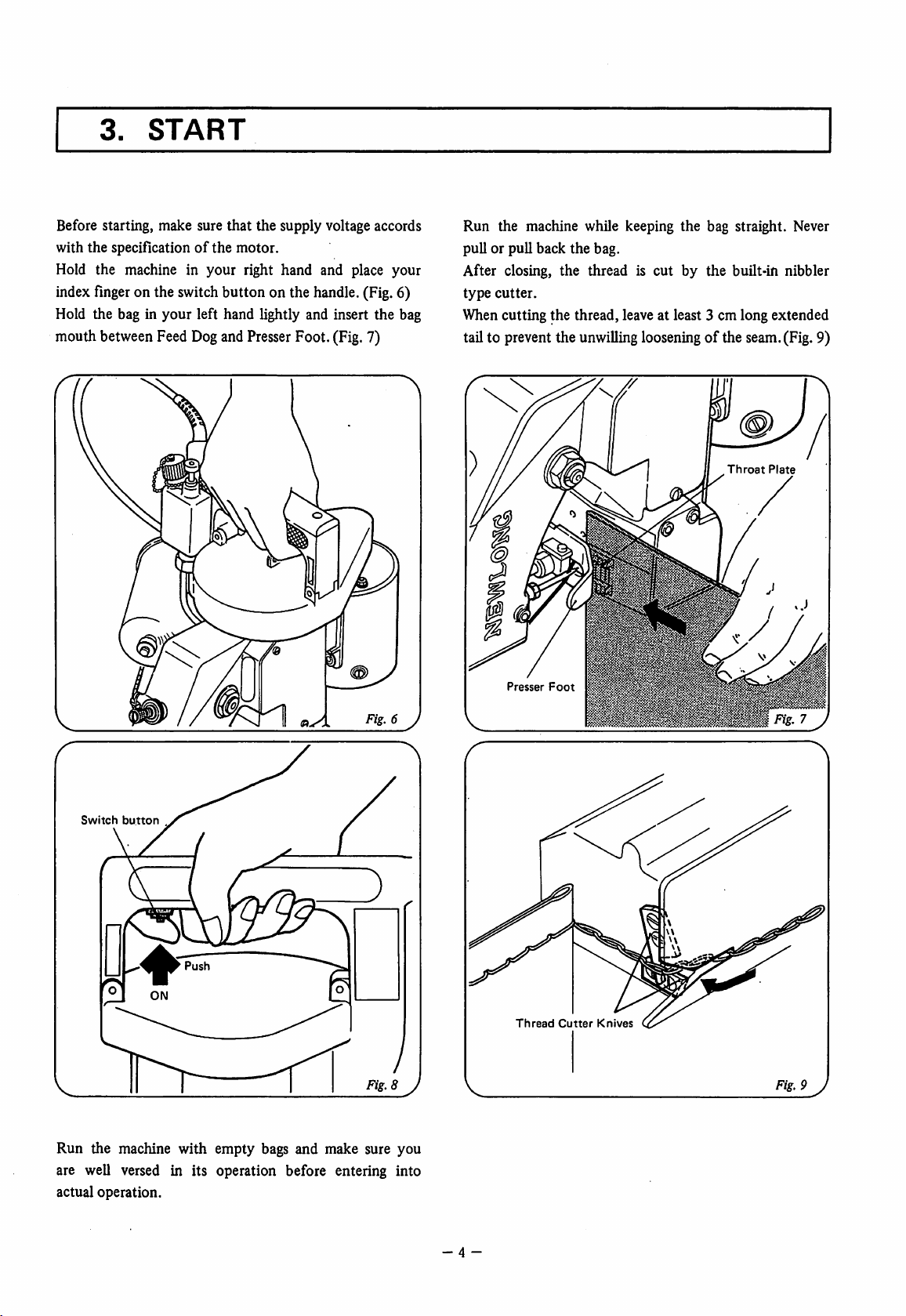
Before starting, make sure that the supply voltage accords
with the specification
of
the motor.
Hold the machine in your right hand and place your
index
finger
on the switchbutton on the handle.(Fig. 6)
Hold the bag in your left hand lightly and insert the bag
mouthbetweenFeed
Dog
and
Presser
Foot.(Fig.7)
Run the machine while keeping
pull or pull back the bag.
the
bag straight. Never
After closing, the thread is cut by the built-in nibbler
type
cutter.
When cutting the thread, leave at least 3 cm long extended
tail to prevent the unwillinglooseningofthe seam.(Fig. 9)
Throat
Plate
I®
Switch
button
Fig.
6 J
Presser
Thread
Foot
Cutter
Knives
Fig.
9J
Run the machine with empty bags and make sure you
are well versed in its operation before entering into
actual operation.
- 4 -
1.
4.
Thread
ADJUSTMENTS
Tension
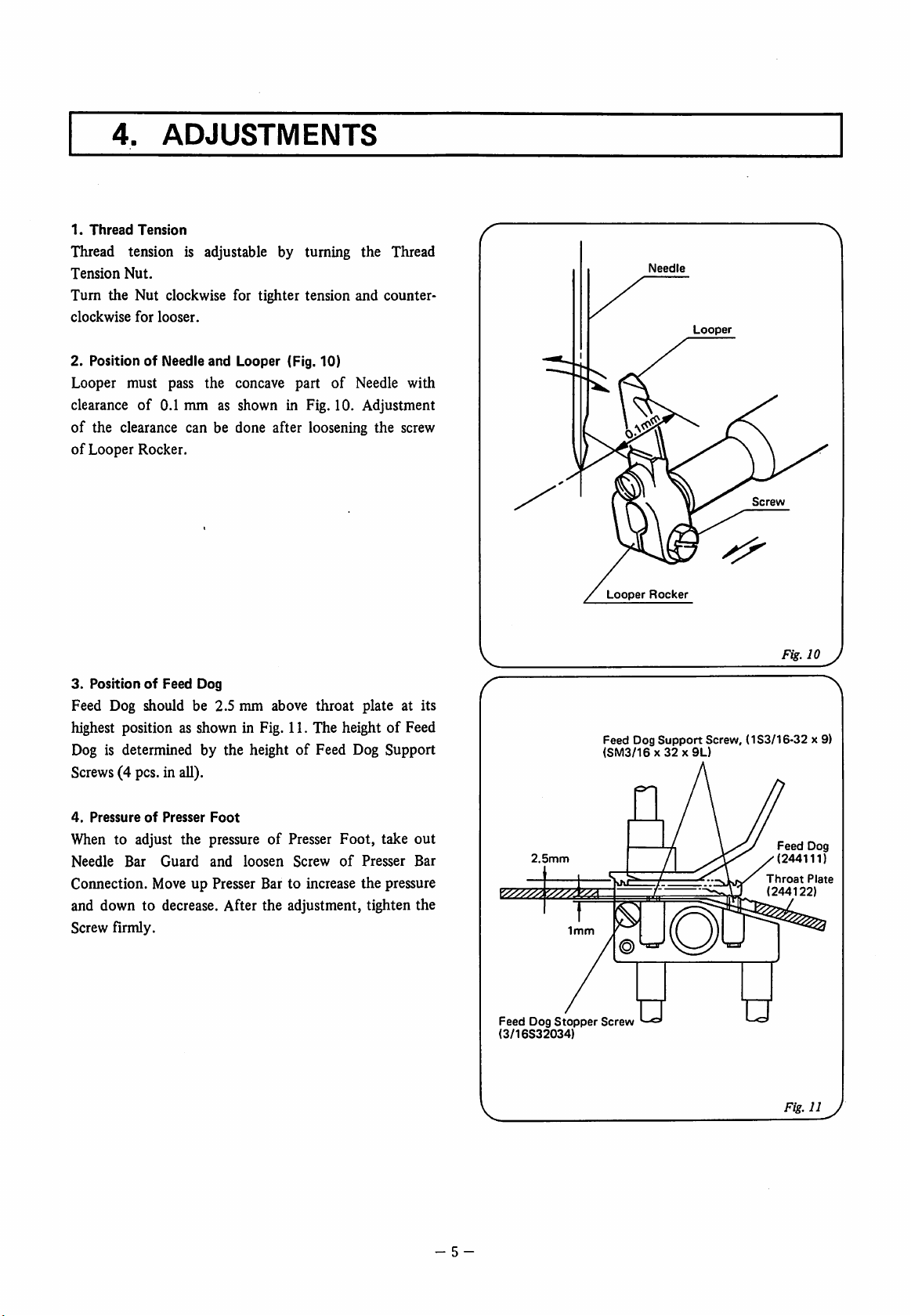
Thread tension is adjustable by turning the Thread
Tension
Nut.
Turn the Nut clockwise for tighter tension and counter
clockwise
for
looser.
Needle
Looper
2. PositionofNeedle
Looper must pass the concave part
clearance
of
of
Looper Rocker.
3.
PositionofFeed
of
the clearance can be done after loosening the screw
Feed Dog should be 2.5 mm above
and
Looper (Fig. 10)
of
Needle with
0.1 mm as shown in Fig. 10. Adjustment
Dog
throat
plate at its
highest position as shown in Fig. 11. The height of Feed
Dog is determined by the heightofFeed Dog Support
Screws(4 pcs. in all).
Looper
Rocker
Feed Dog
(SM3/16x32x9L)
Support
Screw
Fig.
10 y
Screw, (1S3/16-32 x 9)
4.
PressureofPresser
Foot
When to adjust the pressure of Presser Foot, take out
Needle
Bar
Guard
and
loosen
Screw
of
Presser
Bar
Connection. Move up Presser Bar to increase the pressure
and down to decrease. After the adjustment, tighten the
Screw firmly.
- 5 -
2.5mm
Feed
Dog
(3/16S32034)
Stopper
Screw
Feed
(244111)
Throat
(244122)
Fig.11J
Dog
Plate
5.
REPLACING
PARTS
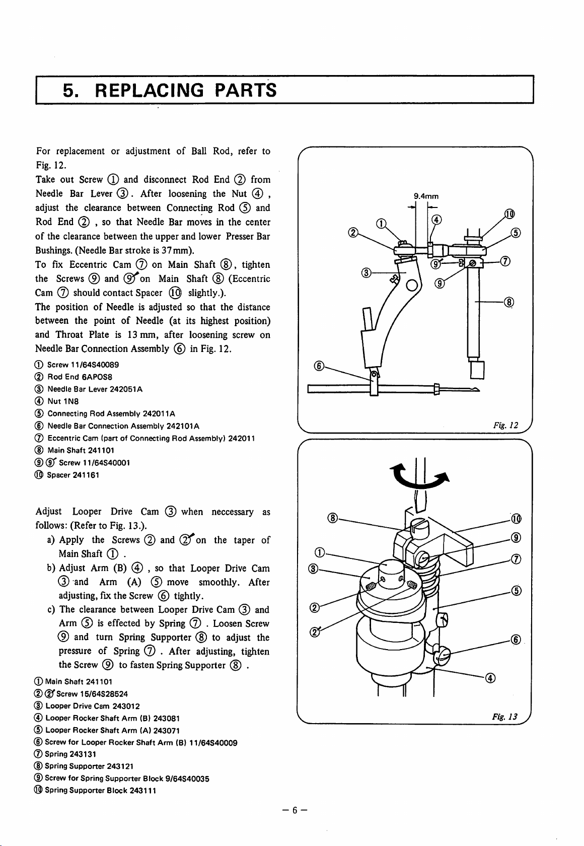
For replacement or adjustment
Fig. 12.
Take
out
Screw
(T)
and
disconnect
Needle
adjust
Rod
of
Bushings.(Needle Bar stroke is 37 mm).
To
the
Cam0should
The positionofNeedle is adjusted so that the distance
between the point of Needle (at its highest position)
and Throat Plate is 13 mm, after loosening screw on
Needle
® Screw 11/64S40089
(D Rod End
(D
® Nut 1N8
(5) Connecting Rod Assembly 242011A
(D
(7) EccentricCam (part of ConnectingRod
(D
CD®'
O Spacer 241161
Bar
Lever
the
clearance
End
(5) , so that
the clearance between the upper and lower Presser Bar
fix
Eccentric
Screws
Needle
Needle
Main
(9)
Bar
Connection
6APOS8
Bar
Lever
BarConnection
Shaft 241101
Screw
11/64S40001
between
Cam
and
contact
242051A
.
After
Needle
0 on
on
Spacer
Assembly
Assembly
of
loosening
Connecting
Bar
moves
Main
Main
Shaft
(0)
slightly.).
0 in
242101A
Assembly)
Ball Rod, refer to
Rod
End
(2)
from
the Nut 0 ,
Rod
0
and
in the
center
Shaft
(8),
tighten
(8)
(Eccentric
Fig.
12.
242011
(D
9.4mm
Fig.
(D
12 J
Adjust
follows: (Refer to Fig. 13.).
(D
®
® Looper
® Looper Rocker Shaft Arm (B)243081
® LooperRocker Shaft Arm (A)243071
®
©Spring 243131
® SpringSupporter 243121
®
®
Looper
a)
Apply
Main
Adjust
b)
0
adjusting,
c)
The
the
Shaft
Arm
and
Arm
fix
clearance
Arm0is
0
and
turn
pressureofSpring
the
Screw
0 to
Main
Shaft 241101
(D"
Screw
15/64S28524
Drive
Cam243012
Screw
for
Looper
Screw
for
Spring
Supporter
Spring
Supporter
Drive
Cam
0
Screws0andQfon
0 .
(B)
0 ,sothat
(A)
0
move
the
Screw0tightly.
between
effectedbySpring
Spring
RockerShaft Arm
Block
0 .
fasten
Block
243111
Looper
Supporter
After
Spring
9/64S40035
when
Looper
smoothly.
Drive
0 .
0 to
adjusting,
Supporter
(B)
11/64S40009
neccessary
the
taper
Drive
Cam
After
Cam0and
Loosen
Screw
adjust
tighten
0 .
as
of
the
(D
(D
m-
(D
U
Fig.
(0)
(D
(D
CD
13 J
- 6 -
6.
MAINTENANCE
&
LUBRICATION
Clean the machine at the endofthe day's work. Wipe
dust and other foreign matter
off
the Feed Dog teeth
Looper and Throat Plate evelets where they are easily
gathered.
Care should be taken to keep the machine free from rust,
especially when to leave it unused for some time.
Important
When adjusting
Thisisimportantinviewofsafetytothe
7.
I
the
machineorreplacing parts, always
LUBRICATOR
operator
disconnect
and
adjuster.
Recommended lubricants are Shell X-100, Motor. Oil
lOW/30, Shell Vitria Oil 31 or the equivalent. For
operation and maintenance
Section
the
7.
Electric Cord
from
the
of
the lubricator, refer to
power
source.
1.
Operation
The lubricator comprises a
pump
and a reservoir. The
reservoir holds max 45 ccofoil. (Effective oil volume
is 28 cc.)
To operate
1. First unscrew
the
lubricator:
the
reservoir capbyhalfaturn.
*
2. Push the button to its lowest position (stroke: 12mm).
3. When released,
the
button
will automatically return
to its original position.
4. Lastly, tighten the cap to prevent oil leak during
operation.
*
Repeated
the
the
when
working
cap
may
dustinthe
the
capisloosened.
produce
atmosphere
on
the
negative
button
without
pressureinthe
maybeeasily
first
reservoir,
introduced
loosening
and
in it
2.
Maintenance
1. Keep
off
dust or foreign matter when to fill oil (They
may cause jammingofthe piston arid the check valve).
2. Rate of discharge is fixed and not adjustable (0.08 cc
per push).
3. At high temperatures, grease may run along points .
This is normal, grease being used when the lubricator
was assembled in our plant.
4. Reservoir is madeofhigh density polyethylene. Keep
off
fire and refrain from using organic, benzene, or
xylene chemicals for cleaning.
Check periodically for correct working of the pump.
(Repeat oil feed and look at the oil through the
discharge pipe.)
7 -
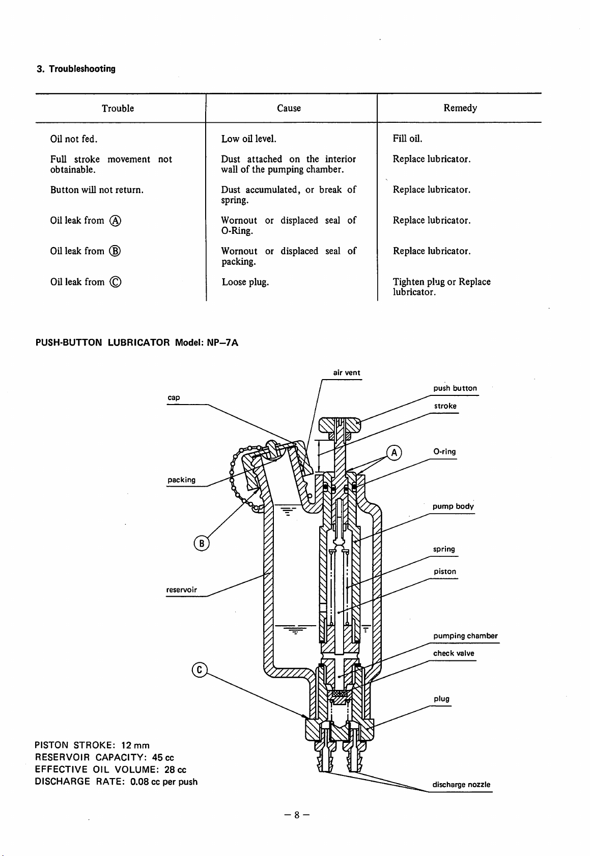
3.
Troubleshooting
Oil
not
fed.
Full
stroke
obtainable.
Button
will
Oilleak from (S)
Oil
leak
from
Oil
leak
from
PUSH
BUTTON
Trouble
movement
not
Low
Dust
oil
level.
attached
Cause
on
the
interior
FiU
oil.
Replace
Remedy
lubricator.
wallofthe pumping chamber.
not
return.
Dust
accumulated,
or
break
spring.
Wornout or displaced seal
of
of
Replace lubricator.
Replace lubricator.
0-Ring.
(§)
Wornout or displaced seal
of
Replace lubricator.
packing.
© Loose plug. Tighten plug or Replace
lubricator.
LUBRICATOR
Model;
NP-7A
air
vent
push
button
packing
reservo
stroke
pump
body
spring
piston
r
pumping
check
chamber
valve
PISTON
RESERVOIR
EFFECTIVE
DISCHARGE
STROKE:
CAPACITY:
OIL
RATE:
12
mm
VOLUME:
0.08ccper
45
28
cc
cc
push
- 8 -
discharge
nozzle
8.
ORDERING
PARTS
The parts list showing all the parts used in the machine is included in this book.
Check the list, and specify parts numbers and quantities required clearly.
Send yourorder to the nearest agent, distributor or one of
our
branch offices.
1. Description of each part and its stamp number is describedin this parts list.
Screws and nuts for parts are shown adjacent to the relevant parts. When ordering parts, describe
clearly
stamp
number
with
its
nameofpart.
2. The parts which have no Ref. Number can not be delivered independently; always order it as an
assembly.
3. A
4.
5.
*
The
setofassembled
The
last figure in
Part
No.
described
part
list is
subjecttochange
(1) THREAD
BUSHINGS,
(2)
(3)
NEEDLE
(4)
LOOPER
parts
is represented by
the
parts stamp number advances on each improvementofthe parts.
in [ ]ofRemarks
TENSION
OILINGS
BAR,
PRESSER
DRIVING
without
prior
AND COVER PARTS 10
AND
HANDLE
BAR
PARTS
means
notice.
AND
the
stamp
old
CONTENTS
PARTS 12
DRIVING
numberofits
part
No.
PARTS
main
parts.
14
16
(5) FEED
(6)
(7)
(8) CREPE
NUMERICAL
DRIVING
MOTOR
SPECIAL
PARTS
PARTS
TAPE
INDEX
AND
THREAD
(ForTotally
FOR NP-7H TYPE 22
BINDING
OF
AND
PARTS
CUTTER
Enclosed
CUTTER
Type
PARTS
- 9 -
PARTS
Motor)
(Special OrderParts) 24
18
20
26
 Loading...