


I
I
SEWING
FIEAD
*trffi=i)
MODEL
9A
9G
9P
=gAW
:gcw
O
nm:ililirn
Iz-I7}?.IXil*rt+ft
t.:.,
For
Operator
Safety
Thank
you
for
purchasing the NLI
Model
DS-9
Bag
Closing
Machine
Head.
o
This manual contains
the
instructions
and
precautions
for
using the
Model DS-9
Bag Closing
Machine
Head. Be
sure
to read and
understand
this manual
before use and
use
the machine correctly.
o
Keep
this manual
near the
sewing machine
for easy
reference.
Be sure
to attach this
manual
to the machine
when lending
or transferring
it
to another
person
or
company.
o
Please orderthis
manual from
the nearest
NLI
office if it is
1ost.
O
The contents
ofthis
manual
are subject
to change
without
prior
notice for improvement
and safety
purpose.
Instructions
with this
mark are
especially
important
for operator
safety.
Be sure to
observe these marked
instructions.
??lc)l,\<
=
= -
E
Y
trTx(ffi)ts-g
4#
n
fiE
i
vvAfs
HL
\tlJL rlc.ldB
6
D
Wi
i
3t,''Ef.
.
.d)WWnnEE=it
DS-e
4*
trfil{-vYary51'filtL
fEH
t
oitH+trr\--E#8iu(v.*f
"
l'&ffi
tfrir:o
WWilf"Fn=?Z.
f
fc
-6fi
4 <
fa
3
L'.
fr
Et + hwWv<
EL<:"fEH(r.3v
''"
.
aaww#,ry
gi*:vyoz
if
i..
v.-crbl'f,uffi
v.r-rd
ir6&i.
{*€L((/d8v'.
DS-e4# tr
F#:v
v
bHL
H
L. EIc t*#Eo E d
tt*.
a
WW;nFfi E
affitfrltffit
L
( (
r. 3
v''
"
.
.DfuWifr.ffi
gAflr^3
tt
t:Edt*==-vY
/T-#-
(ffi)AtrEf6rtr
i.:'ill <
/l'3
v''.
.
.aWW=,nEE
g
iJ&HE Fl
L*ir-l** 4.at:d>
.
a E
tV
F-4E.fatLrt\bD*-tr"
fiav-,
ttEe-t'++l=EEE/JrH E
t'
t
"
il't.t;tuJ(EEut"
ElWfe,B.
o
DS-ec
4 E #Dt
y
I
-
|l:v/
b lfr.H
F
tilt
v
F
-
a
'ff
9rf
.
ffiEDl
t-tr 6*tr1fi\br9*f"
:v)' l.&ft
ffr-"-rb\fia(v\*f.
)t
v
I
-
VJ
a[(
[196
g
$
/31
ta'(/3f
$1,
t"
8iAtrH
o iv), l.# tffi
^t
6F+,lt.
iEHL/rv
t
&flt#F-&
i
rffi
1r
63
6
*tLA k
Z t1$\bD
*t
"
o
:
J/y
t. i*#iAiIH'.v-
2
LEE->
<
v,*f
.
ffi
iti
y>,
DT
l[\bi66& i.
+
tj:v)/
l.
EEs
t2 b
/rl/'I
i
l.
ilHL((/dst,.'"
A*"=rd
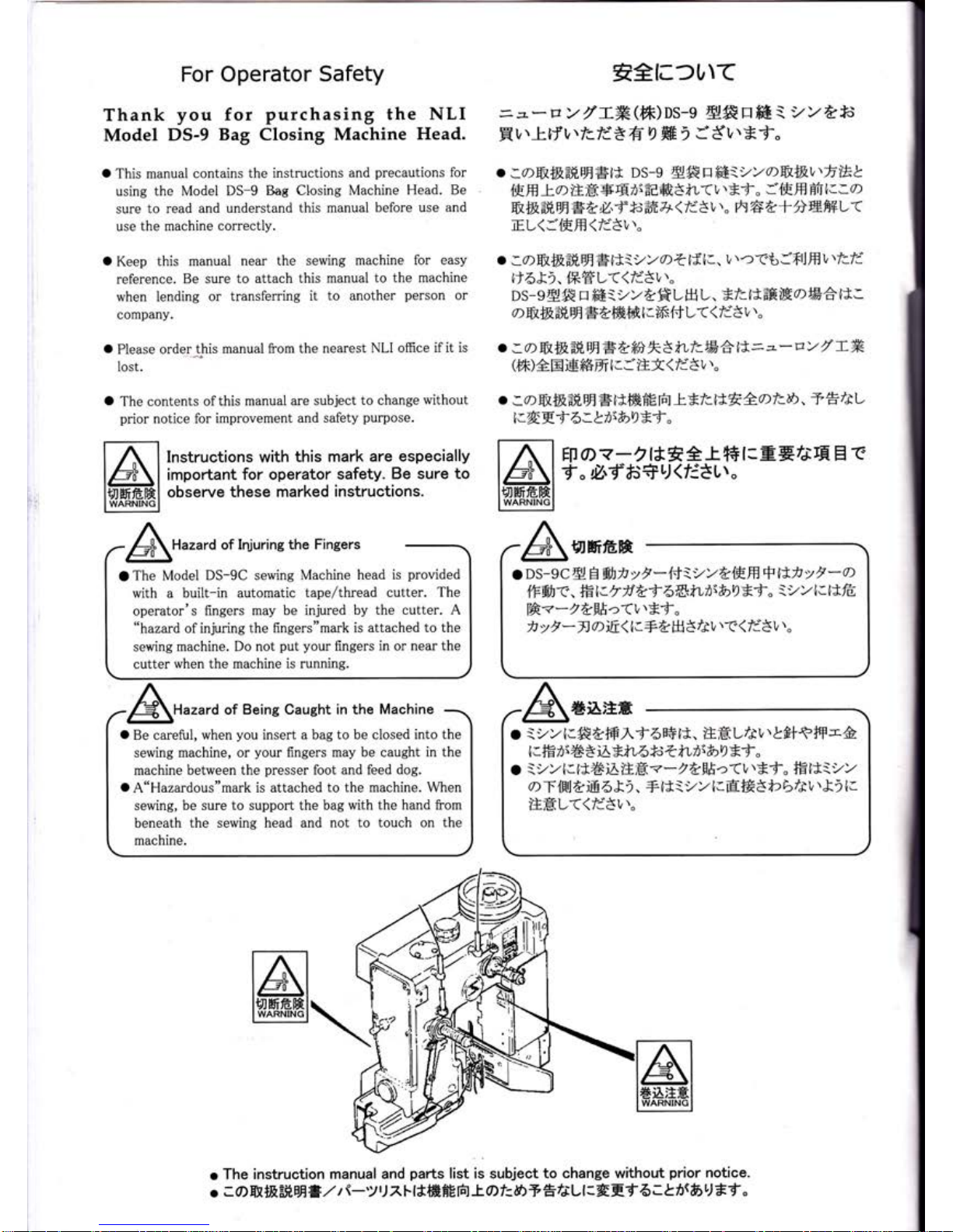
of Injuring
the Fingers
O
The Model
DS-9C sewing Machine
head is
provided
with a built-in
automatic tape/thread
cutter.
The
operator's
fingers
may be injured
by the cutter.
A
"hazard
ofinjuring
the
flngers"mark is
attached to the
sewing
machine. Do not
put your
flngers
in
or
near the
cutter
when the machine is running.
Hazard of
Being Caught in the
Machine
o
Be careful,
when
you
insert
a bag to be closed
into the
sewing
machine, or
your
fingers
may be caught in
the
machine
between the
presser
foot
and feed dog.
O
A"Hazardous"mark
is attached to
the machine. \Mhen
sewing,
be sure to support the bag
with the hand from
beneath
the sewing head and not
to touch on the
machine.
o
The
instruction
manual and
parts
list is subject
to change without
prior
notice.
o
; 0)
ffi *E
-#
flfr#,2
t
\-y'J
7.
F
ltffi
HE frt
-t-
A t=
&>
A fr
/i
L
I
:
4 E
t 6
z
t hrbu
tt
"
l.
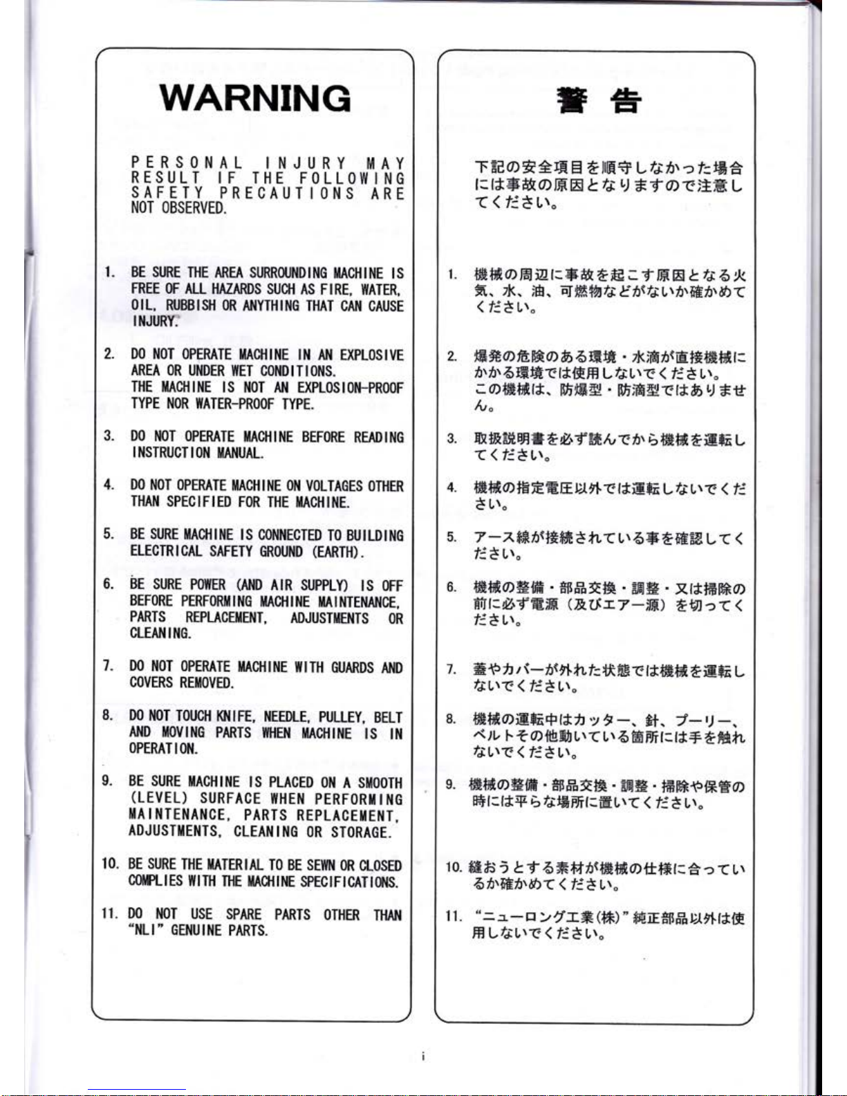
WARNING
PERSONAL
INJURY
rvlAY
RESULT
IF THE FOLLOl|llING
SAFETY
PRECAUTIONS
ARE
NOT
OBSERVED.
BE SI'RE
IHE
AREA SURRflJNDING
I|ACHINE
IS
FREE
F
AI-I HAZARDS
SU$I
AS FIRE,
WATER,
OIL,
RUBISH
OR
AIIYTHING
THAT CAN
CAUSE
IIIJI'RI?
D0
NOT 0PERATE
ITACHINE
ll'l
AN EXPL0SIVE
AREA OR
UNDER
IIET
CONDITIONS.
THE
IIACHINE
IS
NOT
N
EXPLOSION_PROOF
TYPE
NOR I{ATER-PROOF
TYPE.
DO NOT
OPERATE
IIACHINE
BEFORE
READING
I NSTRUCT
IOII
IIANUAL.
DO
NOT
OPERATE
I|ACHINE ON
VOLTAGES OTHER
THAI{
SPECIFIED
FOR THE
HACHINE.
BE SURE
iIACHII{E
IS CONI{ECTED
TO BUILDTNG
ELECTRICAL
SAFETY
GROUIID
(EARTH).
Br
sunr
PowER
(ND
AtR
suppln
ts oFF
BEF0RE
PERF0RIilll'lG
MACHINE
iilAII'ITENAI'ICE,
PARTS
REPLACETENT,
ADJUSTMENTS
OR
CLEAI.IING.
DO
].IOT
OPERATE
IIACHINE
IIITH
GUARDS
ND
COVERS
REIIIOVED.
D0
NOT
T0UCH
Kl,llFE,
NEEDLE,
PULLEY,
BELT
AllD
ilOvltlc
PARTS
I{HEI'I
IIACHIItE
lS
It{
OPERAT
I ON.
BE SURE
IIACHINE
IS
PLACED
ON
A SIIIOOTH
(LEVEL)
SURFACE
ITHEN
PERFORiIIIIG
li|AINTENANCE,
PARTS
REPLACE[lEl'IT,
ADJUSTIIEiITS,
CLEANING
OR
STORAGE.
BE SURE
THE
MATERIAL
TO BE SE[{N
OR
CLOSED
COIPLIES
I{llH
THE I'lA$llNE
SPECIFICATIOI{S.
DO
NOT USE
SPARE
PARTS OTHER
THAN
.ilLI'
GET'IUINE
PARTS.
7.
3.
5.
10.
11.
1.
=#
TEts0)EAE
EI
EilH+
L
Tj75\
ct=EA
l: r*FfifoHtr
t
ti
L)
tf
o r;tH
t
((EtL'r"
ffi {fr
CIE
izt:gg
tfrE
;
f
H
tr
t.
re
6
!<
fi.
zk.
iH. EIffi+A/e Ez5rtL\fr\fiEf\d5(
(
f;*
ur"
R#@ftWa
b
6ffiffi
.
zl<;ffi
nttrf*#fift t:
i'z5r6ffiHr{*{HH
LfjL\r
(
fi*
ur"
;offifif;r*.
[fr,84
'
tffiffi4rr*6r.J *rf
/v"
m+e#,Ef
=
eil'E--fr/vti\
6ffiffieE+E
t
((E*ur"
ffififioEEEElJrt
Et*EFa
LfJr\r
< ri
t
u\.
7
-^
fi*6r+*ffi
* fL(
L\
5=F
effiffi
L
<
<
Et
Lr"
ffiffi@#ffi
-
#rrffi
El&
-
EEl#
-
xrtffimo)
Hf{:Z.f
E;If,
(&(.[rV-til
ttJtcT
(
fi81r,
H {5,
z t-z5ift*rf:
Ut
ffi
t
t*ffi
ffi
e
E+A
L
/JLrrS
(
Ett,r"
ffiffioiEFi+lt,
y
f
-,
8t.
a-.)
-.
,t/1,
l-
t
o
lfrgJL\
(
L\
6
ffi ffi
t=t*+
tffi)rL
fJLrC (
E8 Ur"
ffiiffi,a#ffi.
*{tFott4
.
FEH
.
tf;EF{p{*E0)
E+t:t*+
bfeBfrt-EL\(
(
E3 Lr.
ffi#j;
Lt
6#fr75rffiffiottt*r:a:
(
Lr
6/t#hr&>(<EtL\"
"=1-p
>rlf,x(ffi)
"
f,fiiE*ftfrDjrll*ffi
H
LfJL\-C
(
E8
Ur"
4.
7.
9.
10.
11.
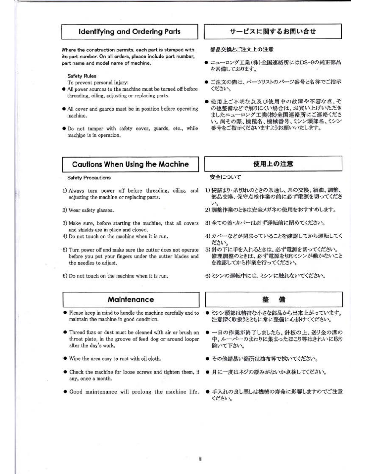
Where
the construction
permits,
each
part
is stamped with
*lIft*fqfJ,EtlO;1H
its
part
number. On all orders,
please
include
part
number,
part
name
and
model name of rnachine.
o
=z*vYfT#(ffi)
AElEffiffilaitDs-9d)ftfi8*fJ#
tffi.{ffiL<*c9*f.
Safety
Rules
To
prevent
personal
injury:
.
:'tstOffiil.
zt*)!xl'Ozi*)*ElAf6(lffim
o
All
power
sources to the machine
must
be
turned offbefore
(li'3V
t.
threading,
oilins, adjusting or
replacing
parts.
o
{Effi
l:j6
EE
/r,F.X.
${EE
+
a)&HtT.#/r,f;
.
t
o
A1l
cover
and
guards
must
be
in
position
before
operating
D{&#lffitf
Etfi49
lc(
V
t
&6^lJ.
f.
H
L
\Ilf
L
tfcld*
machine.
*Llc.=,,.-vYr''f#(*)eEig*6trl.aB*F<fl3
u\"
BitDm,ffiffi*. ffiffi66.
ii/)/@fi5#.
:i/)/
t
Do
not
tamper
with
safety
cover,
guards,
etc.,
while
6ts4:ffim(ld8t,t*f&)*sffiV'.'vtlcL*-d-"
maehllre
is
in operation.
ldentifying ond Ordering
Pqrls
Coulions
When Using
ihe Mochine
Mqintenonce
tt-
t'xr:EEf
6 fjF6L\et
EHl'OtrH
gffi
Safety Precautions tA{:eUtf
1)Always turn
po$rer
off
before threadins, oilins, and
1)f;E=#X9'iAEJtLatZDXiiEL,
X\D*&,ffi&.ffi#.
adjusting the
machine
or replacins
parts.
*tJffit&. {*+,f;&{f#a-ffii.Z,fE,ffi&9lc((Id3
l/\"
2) Wear safety
srasses.
2)ffi*{F#0>}SEAAlrrz^alFHt*;ffDLEf"
3) Make
sure, before starting the machine,
that
all covers
3)A(O#'iz\-itZ'fIEEBfrlaffiD((fl5v''"
and shields are in
place
and closed.
4) Do not touch
on
the
machine when it
is run.
4)
f
zr*fta*iiffiEa(lrr6:LAffiffiL(r)BiEEL(<
fd8u."
5)
Turn
power
off
and make sure the cutter
does
not operate
5)
ffl)Tla+b^tLbL*lt.
/'f€rHt9]-a((Idttr
''"
before
you put your
fingers
under the
cutter blades
and
l6E.ffi*.Ctelt.
Z.f€ffitgJ0:yy7)rfi7)r/3trta|
the needles to adjust.
&ffiffiL(i.btF#.t'fr">((ld3tr\"
6) Do
not
touch on the machine
when
it is run. 6):y)/OiEE$lclt.
iyyl.mful31ta47351rt"
o
Please keep in mind to handle the machine
carefirlly and to
o
iyvEF*t5ltffiffi/ed.3/e*Ilffii.bH*trrr<L\*f.
maintain the machine in
good
condition.
ilHW<&$RiL&6tlHt:Effitl,L.fSiJ((li3V',.
o
Thread tuzz or
dust
must be cleaned with air
or brush on
o
-
E
A+FXrtrK-f
L*Llcb.
fi+ffi"D k,
*9&.0>l#0>
throat
plate,
in the
groove
of feed dog
or
around
looper
F,
tL-z{*a*bDIaR*aftl8LDS}*B*t,U\la}fi'9
after
the day's work.
ffiL\(T$L\"
o
Wipe
the area easy to rust with
oil cloth.
.
ZD{frffiDL\ffiEtr}*lH&'gaffiVt((fd8Vl"
o
Check the machine for loose screws and tighten
them,
if
o
E
lc-Eltt-rDffi.\fiiltL\r\,F,ffrL((ld3v''.
any,
once a month,
o
Good maintenance
will
prolong
the machine life.
o
+y'.fi,ORLHLttt#ffia#frIc**#L*fOfa'igH
(li8v''"
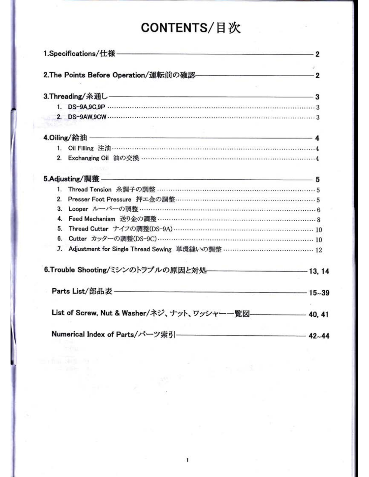
CONTENTS/
flYK
1
.Specifications/tlffi
2.The Points
Before
Operation/trEBta>ffiffi
2
S.Threadins/XiiEL
a.oiline/#iH
1. oil
Filline
EiH.
.......4
2.
Exchaneins Oil
mot&-..
.......4
5.A{iustine/ffiW
1 .
Thread Tension
fnffi+Offi#.
....
.
.
....
s
2. Presser
Foot
Pressure
fF-&OffiW....
......
s
3.
Looper tv*t\*61EHH.
.....6
4. Feed
Mechanism
E9&OAEB
. ...
........
8
5. Thread
cutter
f47Dffi#(ps-ge)
....
10
6. Cutter
)tyV*0tiffi#Os-9c)
....t0
7.
Adjustmentfor,
Single
Thread
Sewing
HffiffirrlOflfi|B.
...L2
o.Trouble
shooting/\yyoh,77*a76ElL*ffe
13,
14
Parts
List/ffiffi*
15-39
List
of Screw,
Nut
& Washer/i9.
fyl..,VyVf--HEl
40, 4l
Numerical Index
of Parts/z{-)ffiE
42-44
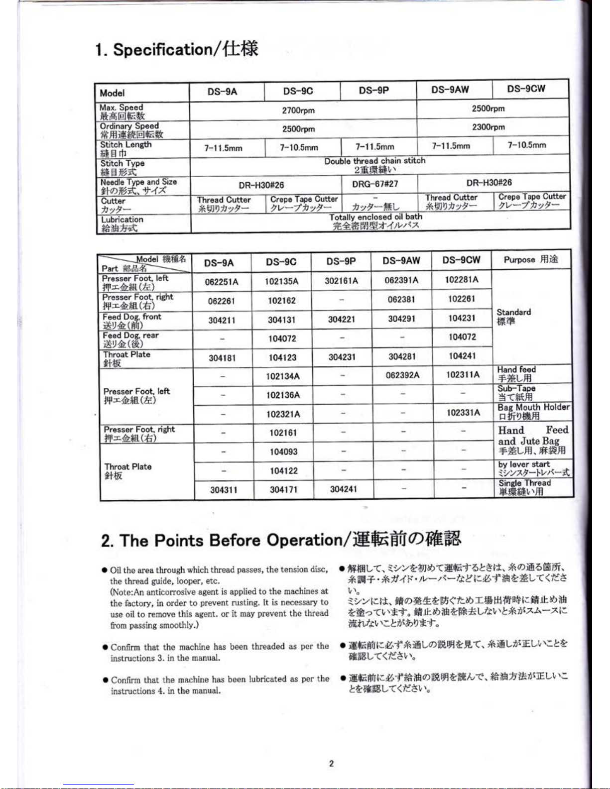
1. Specification/ftffi
2.
The Points
Before
Operation/EffitfrOffiffi
o
Oil
the
area
through
which
thread
passes,
the tension
disc,
the
thread
guide,
Iooper,
etc.
(Note;An
anticorrosive
agent
is
applied to
the machines
at
the
factory, in order
to
prevent
rusting. It
is necessary
to
use oil to remove
this
agent. or it
may
prevent
the
thread
from
passing
smoothly.)
o
Conirm
that
the machine
has
been
threaded
as
per
the
instructions
3. in
the
manual.
o
Confirm
that the
machine
has
been
lubricated
as
per
the
instructions
4. in
the
manual.
o
fi+mL<.
-vY
trylh<trEf
6LE
l*' *\'0)i&6ffifr
'
X\ffi+.
*il
4 F'
tv
-z{-
/r
D
lrfl.f
$
aEL(
<
fd
I
v\o
ivvt.
tt.
ffi
aXEtW
{
ir.d>Tffi
frffi
ffi
lrffi
rL D
ffi
?6a
(1,'Ef"
ffi
Lt.E
iH
&[A*L/ev''t/A
rixA-x
l.
Sfifu/rvl:Lrr&)!*f"
ffiffiL((/d5v''.
o
iEEBtl.U'ff€'lHoil
H
tffi/-<, f#ffif,EntrEuv
'':
&AaEffi'L(<fd3l,\"
1
I
l
l
Model
DS-9A
DS-gC
DS-9P
DS.gAW
DS_gCW
Max.
Speed
frHtr]E&
2700rpm
2500rpm
Ordinary
Speed
HffiEffiEffi&
2500rpm
2300rpm
Stitch
Length
ffiH
rfr
7-11.5mm
7-10.5mm
7-11.Smm
7-11.5mm
7-10.5mm
Stitch
Type
fi48#"2fr
Fouble
thread chain
stitch
28ffiffi1,'
Needle
Type and
Size
#laY,,*^ t4A
DR-H30#26
DRG-67#27
DR-H30#26
Cutter
itvF*
Thread Cutter
*,VJDtvl*
Crepe
Tape
Gutter
,v"/fiyr-
tt"rrylfl.tv
Thread
Gutter
*<6lD)tvF-
Grepe
Tape
Gutter
tv*/)tvF-
Lubrication
ffitH6fr
resedoilbath
frAffif'f,Ht4tv"sz
--..-_Modet
ffifEft
Part*IIfr#i--i
-
DS-9A
DS-gC
DS-9P
DS_gAW
DS-9GW
Purpose HE
Presser
Foot,
left
#-&#s.(E)
062251A
102135A
302161A
062391
A
1022814
Standard
ffiry
Presser
Foot, right
ffi-&*tr(fi)
a62261
102162
062381
1A2261
Feed
lfog,
tront
Er&(Et)
304211
3041
31
304221
304291
104231
Feed Dog,
rear
Xt&.(th)
104072
104072
Throat
Plate
AFfiE
3041 81
104123
304231
304281
104241
Presser
Foot,
left
ffi-A*E(la)
1 021 34A
062392A
10231
1A
Hand
feed
+#Lffi
102136A
Sub-Tape
g<ffiffi
1023214
t02s31A
Bag
Mouth
Holder
affiu)wH
Presser
Foot,
right
#-6ffi(E)
1021
61
Iland
Feed
and
Jute
Bag
+ELH.
ffi#H
Throat
Plate
e+ffi.
1 04093
104122
by
lever staft
iyyxt-1.1.,/\-{
30431
1
3041 71 304241
Single
Thread
HffiffiVTH
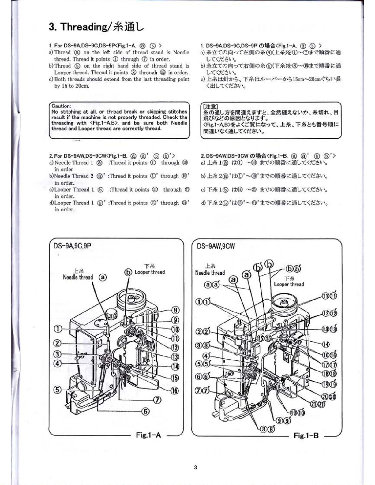
3. Threadins/friEL
1. ForDS-9A,DS-9C,DS-9P(Fig.1-A.
@ @
>
a) Thread
@
on the left side
of
thread
stand is Needle
thread. Thread it
points
O
throueh @ in order.
b) Thread
@
on the
right
hand
side
of thread stand is
Looper
thread. Thread it
points
@
through @ in order.
c) Both
threads should
extend
from the last threading
point
by 15
to 20cm.
1. DS-eA,DS-e0,DS-9P 0)Efi<rie.l-A.
@ @
>
a)
i6
ir(
o
rto
->a
El$lo
*<@
G'tr ) AO
-@Erl[F6
E iE
L(<fa'8v\"
b) iA
ir
(
o
rFJ
c\
h lill
0)
*,
@
(
T
i6
)
A@
-
@
E
tllF6
I
r
iE
L((/i8v',"
c)
t i6
l*fi
n'
6.
T/A
li.tv
-
f
*
71.
b
1 5cm-20cm
{ b
t,'E
(HL((/dEv',"
Caution:
No stitching at all, or thread break or skipping stitches
result if
t}te
machine is
not
properly
threaded.
Check the
threading
with
(Fis.l-A,B),
and be sure both Needle
thread and Looper thread are correctly thread.
DEH]
lRaiEVfi
*F"1
EZ*f
t. A*ffi er*u
tit.
*fl
*t.
El
fttXfa&"0>lHtrbfsL)*t
"
(Fig.l
-A,B)f &
(f
H
l:/au
(.
-t.
#.
T
#
&t,iFEllLE
l:
FpliEtrfa(iEL<<EtL\"
2.DS-eAW,DS-9CW
@l6d/.Gie.t-B.
@
@' @
o'>
a)
-L.i6
1@
t*O
-@
*reol|[FE{.rEL((IdSv''.
b)
tX
2@'
i*O'
-@'
*tolllH6[.iEL((fd3v''"
c)
T/6
1@
lt@
-@
*<"olrF#l.iEL<(li'3t,."
d)
TX
2O)'
lt@'
-@'E-eol{E6t.iEL<(li3t,
''"
2.
For DS-9AW,DS-9GW(Fig.1-8.
@ @'
a)
Needle
Thread 1
@
:Thread it
points
in order
b)Needle
Thread 2
@'
:Thread it
points
in order.
c)Looper Thread 1
@
:Thread it
points
in
order.
d)Looper
Thread I
@'
:Thread
it
points
in order.
@ @'>
O
through
@
O'
through
@'
@
throush
@
@'
through
@'
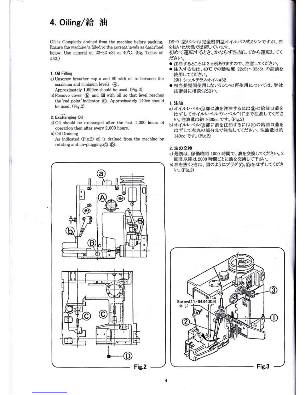
4.
oilin
g/t#
lH
Oil is
Completly
drained from the machine
before
packing.
Ensure the machrne
is fl1led to the correct
levels
as descdbed
below.
Use
mineral al
22-32
cSt
at 40"C.
(Eg.
Tellus oil
#32.)
1.
Oil Filling
a) Unscrew
breather cap
a
and fiIl
with oil
to
between
the
maximum and
minimum levels
@.
Approximately
1,600cc should
be used.
(Fig.2)
b)Remove
cover
@
and flll with oil so
that level reaches
the'red
point'indicator
@.
Approximately 140cc
should
be used.
(Fig.2)
2. Exchanging
Oil
a) Oil should
be exchanged
after the flrst
1,000
hours
of
operation
then
after
every
2,000
hours.
u)
Oit
oraining
As indicated
(n'ie.Z)
oil is drained ilom
the machine by
rotating and
un-pluggine.@,
@.
&f&t,
rfcfif
B< H{f
L<
l,
\Ef
"
AID
(rE6f
6&ts.
i'/ebf
iEffi
L(D'
biEEL(<
ld'St't.
.
iIiH9-6L.4t&2
*rt&>9*f
ar.
iEffiL<(/i3t,'"
.
lE,\f6iH
t*,
40'C(0)ffi
fEE
22cSt-32cSt
offilfrb
ffiffiL(<rd8u''"
(Frl)
y-tv77zft-4tvnzz
.
+E
g
EH f5t€,ffi
ur3p'1
vv
aFffi-Hlc-?u
\(l*.
#+t
&ffiElcfgff(A8vt.
1.
E'fi
a)
zt
4
tvv
*/r,
@
*11
[I.
ffi
&EH
16
l.lt
@
o
ffi
ffi
tr
HA
i*
f
L
-6
r--1'
)v
V'\
)v
q)
v'r'.rl,
"
H"
* T lI lH
L
(
<
fd 3
L\"
iEmEt**!
tooocc
-(f"
(Fie.2)
b)
*
4
tvv
*/L@
H3
t.m AiElHf 6
l. rtG)
o*a'ffi
tr
#a
it-d-L(#
JL
7)
ffi A*r&ifr
L(
<
rd8
r,',.
lI&
Et*ffr
140cc
Tf"
(Fig.2)
2.ifraf'+a
d &?nE. f*Eifl+Ffr
1000
F+FHl-f.
-{frt{,&t-<(fi3t,''.
z
El
E
D-lffilt 2000
ffiFfrSLlriHAt&L(T8t,."
b)
ffi&&<&tst*.
EXd)Xir.77f
@,€)AEf
L(<fi8
1,
r.
(Fig.2)
I
'-iM
Screw(1 1
/6454009)
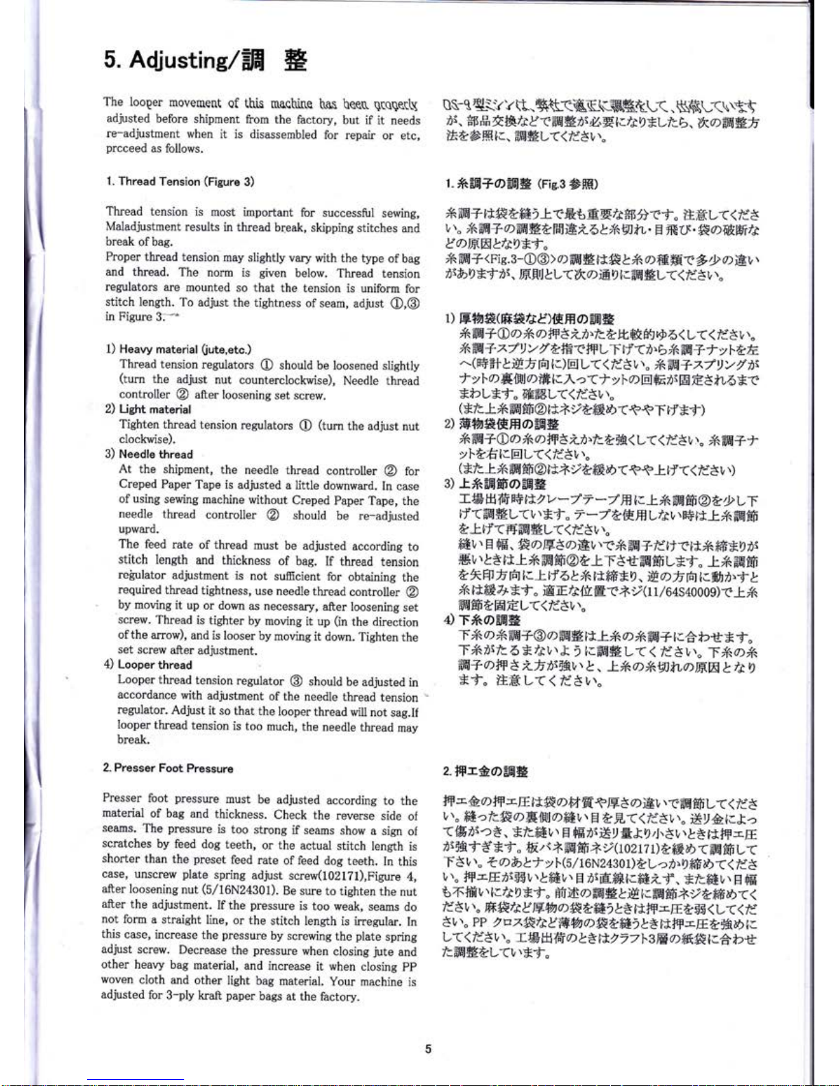
5. Adjusting/Elf
H
The
looper
movernent
of
this
rnaqh.i&e
tr-as
hee(r
qrcge(L\
adjusted
before
shiprnent
from the
factory,
but
if it
needs
re-adjustment
when
it is disassembled
for repair
or
etc,
prcceed
as
foilows.
1. Thread
Tension
(figure
3)
Thread tension
is
most important
for successful
sewing,
Maiadjustment
results
in thread
break,
skipping
stitches
and
break
ofbag.
Proper
thread
tension
may slightly
vary
with the
type
of bag
and thread.
The
norm
is
given
below.
Thread
tension
regulators
are mounted
so
that the
tension
is uniform
for
stitch length.
To
adjust the
tightness
of seam,
adjust
O,@
in
Figure
3:*
1) Heavy
material
fiute,etc.)
Thread tension
regulators
O
should
be loosened slightly
(turn
the
adjust
nut counterclockwise),
Needle thread
controller
@
after
loosening
set screw.
2)
Lisht material
Tighten
thread
tension
regulators
O
(turn
the adjust
nut
clockwise).
3) Needle
thread
At
the shipment,
the
needle
thread
controller
@
for
Creped
Paper
Tape is
adjusted
a iittle
downward.
In case
of using
sewing
machine
without
Creped
paper
Tape, the
needle
thread
controller
@
should
be re-adjusted
upward.
The feed
rate
of
thread
must
be adjusted
according
to
stitch
leneth
and
thickness
of bag.
If thread
tension
regulator
adjustment
is
not
sufficient
for
obtaining
the
required
thread
tightness,
use
needle
thread
controller
@
by moving
it
up
or down
as
necessary,
after
loosening
set
screw.
Thread
is tighter
by
moving
it up
(in
the direction
of the
arrow),
and
is looser
by
moving
it
down.
Tighten the
set
screw
after
adjustment.
4)
Looper
thread
Looper
thread
tension
regulator
@
should
be
adjusted
in
accordance
with
adjustment
of
the
needle
thread
tension
=
regulator.
Adjust
it
so that
the
looper
thread
will
not
sag.lf
looper
thread
tension
is too
much,
the
needle
thread
may
break.
2- Presser
Foot
Pressure
Presser
foot
pressure
must
be
adjusted
according
to
the
material
of bag
and
thickness.
Check the
reverse
side
o{
searns.
The
pressure
is too
strong
if seams
show
a sign
of
scratches
by
feed
dog teeth,
or the
actual
stitch
length
is
shorter
than
the
preset
feed
rate
of
feed
dog
teeth.
In
this
case,
unscrew
plate
spring
adjust
screw(102171),Figure
4,
after
loosening
nut
(5/16N24301).
Be sure
to tighten
the
nut
after
the
adjustment.
If the
pressure
is
too weak,
seams
do
not
form
a straight
line,
or
the
stiteh
length
is irregular.
In
this
case,
increase
the
pressure
by screwing
the
plate
spring
adjust
screw.
Decrease
the
pressure
when
closing
jute
and
other
heavy
bag
material,
and increase
it when
closing
pp
woven
cloth
and
other
light
bag
material.
your
machine
is
adjusted
for
3-ply
kraft
paper
bags
at the
factory.
avtq\VvR.S$IK(\CnKKtL<.$\K\-;(\\g$'
7)r.
sl3
gil
tf4/r
D("ffi
E
n\il.
E
i./i
g
ELft.b. tkq)ffi*fi
'tEt
E ffit..
EEt*
L((
/i3
v''"
l.
#-EJA+odElB
(rie.s
6ffi1)
X
AH+
tt#&ffi
i
l^-eft684/r*[A-ef"
iIHL<<
fis
v
\"
Xffi
+
offi
Ha
HEi 6
LNrrrJtL.
E ft
Lrt.
#o ffiWtt
&"oFtr&la9*f.
#
ffi
+
<p'rs.3-o@>
o
ffi
#
i*# &
#
offi
ffic
&
D
a&v,
,s&)9E:f
,r.
trErJ&L(ltCIiE4 I.EE*L(<ra'8r,
\"
1)
tr{rr*(ffi
*A&)f€H o
3EI
*
*ffi
+
@
D
*r) fF 3 ii./c
t tu#fr\
vg
6( L
(
(
ti' 3
v
r"
X\ffi
+
^7
t)
y
I &ffi<frLT rf
(D.b
#ffi
7f
yltE
^(E+-=#&rEf
Ifi
lt)
g
1_a
a
Id8
r,..
#ffi+
^7
y
y
/
ti
t
ylaF.luoffi
t.
?(J-
yT.o
ElErr
En
€3
tu6E-e
**2L*f"
EEffiL(<fdSL\.
(*Ic-t.fr
EEfifi
@t
*i,
tffiD r++T
d*f
)
2)
ffi{a*ffiHo-dag
i6ffi
+Oo
X
o
ilfl
3 ii.f:Adfi
<
L(<fdtu
r.
5
p67*
vl-&fi[.81L((ldsr,r"
3)
r*EEffiof,aE
Tw
fiffi
E+
rX'
v
-
7
7
*7
fr
t.
.E'
X
ffi
fiF
@
t D
LT
LJ(=aE#L(L
\
Xf
"
7
*7
t
{F.ffiL/i
r,
\
H
ttt,if
aE€F
at'd(FffiBL(<rd3v\.
f6v'' H
fiE.
#otr8o)EL
\-e/A
aB+rdtrrE#
ffffE9
rr
ffi
r,
\I*
t*t*
ffi
€F@A-LT8tffiffi
LEf.
.E'tr
;EfiF
L
kW fr
fi
I.-t
tf
6 L
fi
t*ffi
*0. ttDfi
frit;.9173'j
I
*
t
Jffi
7t
*-t'"
iE
rE
/e
{f
E
r
+,
(
1 1
/64
s 40
0 0 9)
-e
t /A
ffi€FaEEL((/i8t''"
4)
T*o5Eg
T *\
a
#ffi+@
o
ffi
# lrt
*
a
;Affi+
tra t2it
*
f
.
T*i\tbtlir,\t
)
fc6g1_a<
fdSv.,"
T/60lA
ifr+
Dfr
3
iraitfi L
\
l,
-9/6
o,/A
gJtv,,t*W
L
tr
ut
*f"
iEHL<(
liSt'r'
z.lH-SoffiE
#F
-&
o
fF
-
'-tr,'tj.#
D
fi
H.tE 3
o
iel,
\
(.=*H
€F
L(
<
ri
3
r,
r"
ffi
cli#
0DFrftl,:.ffii,\
H AF,(<fi8L."
Elr&lrI->
A.
Ert\.>
*,
Elcffi
r,
r
E
fE-
rt*,
E&
g
4. 3
v.
LE
l*#F-E
,r
tfi
f
3- *?-.
fEu
s
*
ffi
frFR
y(l
02
I 7 1)
tfrX
O
<
ffiFtrV<
T
3
r,''
"
z
a
b t
-f
y
I.
(5/
1
6N243
0 L)
tt-
->
t1,
g
fr#E
r
<
rd
3
l,
t"
#f
-E
/i
$$
l,
r
|
ffi
!,
r
E
nl
Effi
lcffi
if
.
E/1fi6
L
\
El fiE-
66ffi
r,.
t:/r
D *f"
Bifi
,)=FlE#trE
lr;6664y
tffi
b><
<
ld5
t,
..
ffi!frfr E
EMz
a*tffi)
t*llffi
-E
&86
<
L(<
fd
3t''"
PP,
n
z$lt?Wryn
OXb{#2}B
i*ffi
-E
b*kd> tt
L((
ld8
t,
r"
TE
tr)ffi
D
L.Z
tX,
77 l.
sE
ofiS#
tlAbrt
t=ffi#tL<L\*,f.
5.
Adiustins/ffi
H
i
I
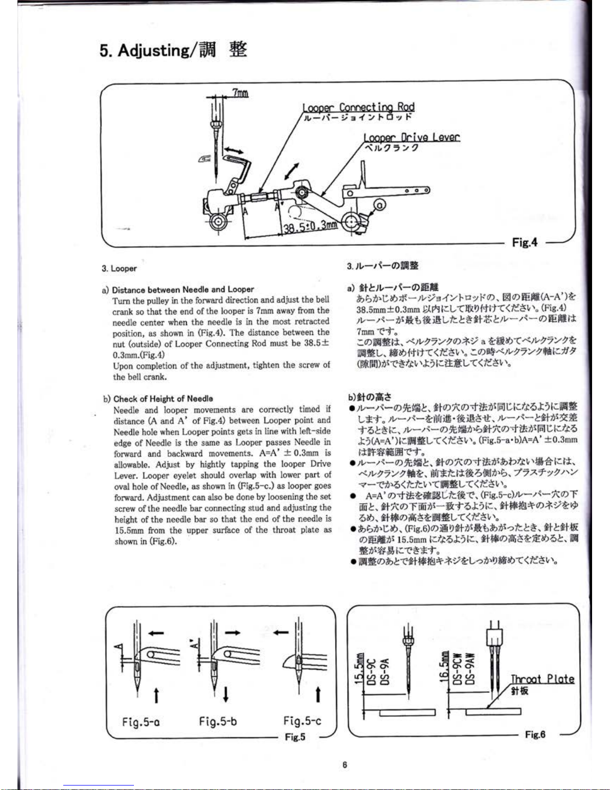
3.
Looper
a)
Distance
between
Needle and
Looper
Turn
the
pulley
in the
forward
direction
and
adjust the
bell
crank so
that the
end ofthe
looper
is 7mm
away from
the
needle center
when
the needle
is in
the most
retracted
position,
as
shown
in
(Fie.4).
The
distance
between
the
nut
(outside)
of Looper
Connecting
Rod
must be
38.5+
0.3mm.(Fis.4)
Upon completion
of
the
adjustment,
tighten
the screw
of
the bell crank.
b) Gheck
of Height of Needle
Needle
and
looper movements
are correctly
timed
if
distance
(A
and A'
of Fie.4)
between
Looper
point
and
Needle
hole
when
Looper
points
gets
in line
with
left-side
edge
of
Needle is the
same
as Looper
passes
Needle in
forward
and backward
movements.
A-A'
+
0.3mm is
allowable.
Adjust by hiehtly
tapping the
looper
Drive
Lever.
Looper eyelet
should overlap
with lower
part
of
oval hole of
Needle, as shown
in
(Fig.5-c.)
as
looper
goes
forward. Adjustment
can
also
be done by loosening
the set
screw ofthe
needle bar
connecting
stud and adjusting
the
height of
the needle bar
so that
the end of
the needle
is
15.5mm
from
the
upper surface of
the throat
plate
as
shown in
(r'ig.o).
s.lt
-r{-oEEE
il fitL.tv-tt-ofEHfi
b bf.Dab
fi
-
tv)
e
4
YI'
r:
v
r*
o.
EX
o
ffi HE(A-A'
)A
3 8. Smm
+
0. 3mm
D[ 6t
llL<E
D
{'i
Lr((
ld8
v
r"
(Fis.
4)
/L-.,{
-
ir
ft
6 f&
ELfc
}
tsfif
Ifi
&zt,
*/{
-
a)
HEE
lt
?mm Tf"
ffi
#L. ffi
E{-t}r< <
Ii3t,',"
a0)W,9v, 7y
2
Wl.tl,
$'H
f6 )
rr
f
B
/*r,
r
&
)
I
cl},e.:
L(
(
li 3
t,
t.
b)ffoH8
o
)v*
t
\*
71trffi
&. t+
D
Ra;;f$-ri
IFJ
D
t./J6
&
2
t.EEg
L*f
.
)v
-
)
s-
?dfriE
"{&
nB3ii.
/lz-"
t
-
I &+rt\rt#
f
6 }*
tc.
)v
-
/
:-
D
fitffifi'E>fi+
fta'f
if
it
IEI
D
tI/r6
&i
[A=A' )
llffi EL<<
fi3l,''"
(Fic.s-a.
b)A=A'
+
0.3mm
itE-f6ffiEflTf"
.
)v*,,s-
o)
taffit,
&+
D
l<D=f #fi:fuN2fst,
tffi6
lclt'
.< p
r'
7
Y
2
ffit.
Ef
E/c tt
lkblW|fi'b,
7
2
zf
v
/
t'v
<
*(-i'6
(
Icrcv
r
(ffi
HL((
IdS
t,
t.
.
A=A'
Orfi**68&ti,Clkc.
(Fie.5-c)
)v*ts*fiqn
ffi
L
-
tI lr,)T ffi
,r-
&f
6
I
i
tr'
f*ffitr6'+
a
*,
L@
6ii.
t+BoH 3 AiE#L(
(
/c'3
t,''.
o
&)
EZ)>DE.
(Fie.
6)
o
rE 4
elD&6
&rnr
o
lc &3.
#+
tfr+
ffi
o)Hffiri
15.5mm
l:.ft635
0..
fr+W0 ttftr,Ab-
ffi
#fi;*D!i_zc8Ef"
.
ffi#Dblfarffiffi
+i
itl-->fi'9ffiD((ff
3
v
t"
]L
r
Fig.5-c
-
Fig.S
tv-tl- i = I
b9a"2
Fig.5-o
Fig.5-b
I
5. Adiustine/ffi
H
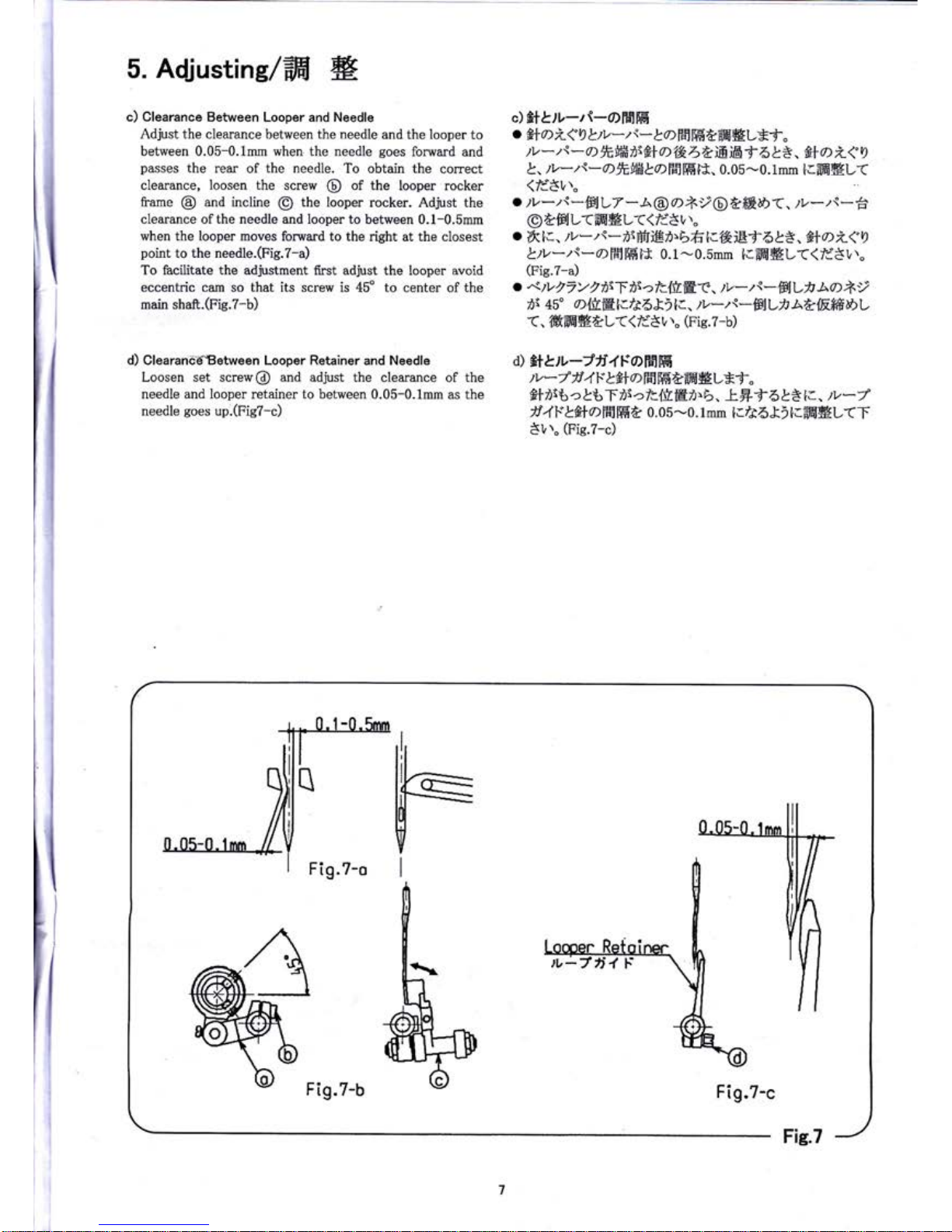
c) Clearance
Between Looper and
Needle
Adjust the
clearance between
the needle
and the looper
to
between 0.05-0.1mm when the needle
goes
forward
and
passes
the
rear of
the needle.
To
obtain
the
corect
clearance,
loosen the
screw
@
of the
looper rocker
frame
@
and incline
@
the looper
rocker. Adjust
the
clearance ofthe
needle and looper
to between 0.1-0.5mm
when the looper
moves fonnard to the
right at the closest
point
to the needle.(Fig.7-a)
To facilitate the adjustment
first adjust the looper avoid
eccentric cam
so that its
screw is 45" to center of the
main shaft.(Fie.7-b)
d) Clearande^Between Looper Retainer
and
Needle
Loosen set screw@ and adjust the
clearance of the
needle and looper
retainer
to between
0.05-0.1mm as the
needle
goes
up.(Fie?-c)
c)
fi+&rt
-/{-o)Fe1ffi
.
&l
D
Z<A b.)v-
t
s-
161ffi
ffi
&ffi
BL*f
"
)v
-
)
s
-
D 9tffi
rt\fr+
D'tk
4a
E iE
f
6 L8. f+o i
{
I
l,
.rl,-z{-
o
ftffit
o:-l1ffiilt.
0.05-0. t mm
t.ffi*L(
(ld$t,''.
.
)v-
):*ff.Ilt7
-
A
@
D+y@
Affi
E
(.
zt,-zt-6'
@AFJL(ffi#L(<rdSl,\"
o
ift
[:.
/r-.,{-
rrBfr ff_,fi)t>fr
ttth.iBf 6}8.
#
D
L< 9
L.tv*
ts-
61H
tffi
E
0.1-0.5mm
t.ffi#L<<li3v',"
(Fie.7-a)
.
,<)vVTYZirTi\ct{trEf
.
)v-/:-'F41-fi
Aa*,
,i
45" CI&E[:./361i
1..
)v-/s-FlL)J
ab{Effie>l-
<,'#\ffi*tL((ri'3
v''"
(Fic.
z-b)
a)
ft
L, tv
-Jli,f
ls
o)
Fpl lE
)v-/
)t
4
ts
l#o
rfi ffi
aaH
gL*f
"
Slir6c &6f
isaft'{trEi'b,
k*-l-
6}*
lr.
)v-7
)f
4
r* Lfi+
rr^lfrffi
t
0. os
-0.
lmm
l./r6Xi irffi
#LrT
Str''"
(Fig.7-c)
Fig.7-o
Fig.7-b
Fig.7-c
Fig.7
!-
I
L
5. Adjustins/ffi
W
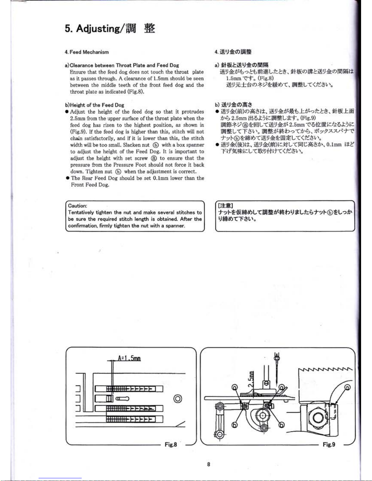
4. Feed
Mechanism
a)Clearance between Throat Plate and
Feed Dog
Ensure that
the feed
dog
does not touch
the
throat
plate
as it
passes
through. A clearance of
1.5mm
should
be seen
between the middle teeth
of the front feed dog and the
throat
plate
as
indicated
(p'k.A).
b)Height of the Feed Dog
o
Adjust
the
height
of the feed dog so that it
protrudes
2.5mm from
the upper surface ofthe throat
plate
when the
feed
dog
has risen
to the
highest
position,
as
shown
in
(p'ig.g).
If the feed
dog
is higher than
this, stitch will not
chain satisfactorily, and if it is lower
than this, the
stitch
width will be too smal1. Slacken nut
@
with a box spanner
to
adjust the height
of
the Feed Dog.
It is
important to
adjust the height with set screw
@
to
ensure that
the
pressure
from
the Pressure Foot should not force it back
down. Tighten nut
@
when
the adjustment
is
correct.
o
The
Rear Feed
Dog should
be
set 0.1mm lower than the
Front
Feed Dog.
Gaution:
Tentatively tishten the
nut
and make several stitches to
be sure the required stitch length is obtained.
After
the
confirmation,
firmly
tighten
the nut with
a spanner.
4-ix'JeOFla*
a)
St*E&iEtJ#oFslffi
E)
&is*:
c
*6 Efr trLf
L3. fltE@ffi
&X, &o
f5
1.5mmTf"
(Fig.B)
EINifo t
tffie><.
ffi*L((lddt,l.
b)
iXu#orat
o
Er#(Bfi)o H3
tt, i*,
&r\Eb
Iii->lcl*.
SitEt
ffi
D.b
2.5mm
H6&il.ffi#L*f"
(Fie.9)
ffiEF*-r@
&EIL(ErADI
2.5mm t6{tEl.A6&i l.
ffi
#L<TS
r,
\.
#l#
ri
ft€*>
cAfi'b,
if
>
2
z ztsaa
J'vF@ &ffi
E
()Xll
Aa
H
EL(<fd8
L
\"
.
E,
A('{&)t*.
Er&(BfI)
icf.f
L<
E
DHSi'.
0. 1mm
l* &"
T
}Jft,*
tr
u(
& I {-.}
!r((
fdsr,',"
ItrH]
ty
l-d
lRffi
a>L
(-aE
*
nrfi
I
b U
*Lt= b tv
F
@
t
L
z z5r
tJ*if,&)(T*t\"
5. Adiusting/ffi
W,
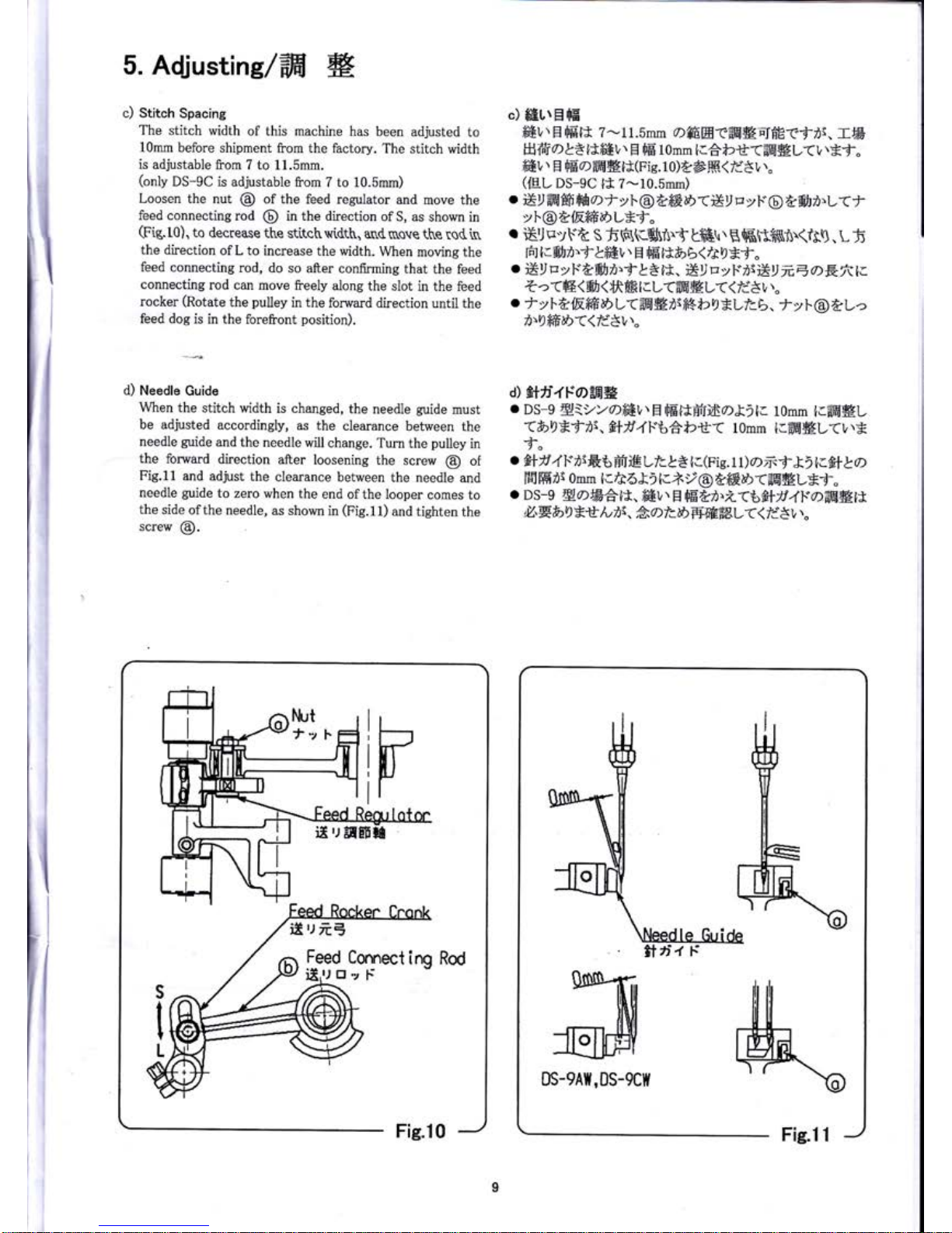
c) Stitcn
Spacins
The stitch
width
of this
machine has
been adjusted
to
10mm before
shipment
from the factory.
The
stitch width
is adjustable
from
7 to 11.5mm.
(only
DS-9C
is adjustable
from 7 to 10.5mm)
Loosen the
nut
@
of
the feed regulator
and
move the
feed connecting
rod
@
in the direction
ofS,
as shown
in
(p'is.tO).
to decrease
the
stitchwtdth,
an(ruove
the
ro(in
the direction
of L to
increase
the width.
When
moving the
feed connecting
rod,
do so after
confirming
that
the feed
connecting
rod can
rnove freely
along
the slot
in the feed
rocker
(Rotate
the
pulley
in the
forward
direction until
the
feed dog
is in the
forefront
position).
c)
#ELtEfE
fEL
\
El
fE-t*
z-1
r.Smm offiEfl
tEE#EI6E-cf
,i.
rB
Hffi
ol*l*mr,.
El
rFE
tomm
tl6i2rt'<ffi
HL<L
\*f.
fi6v'' H
fEod6*t*(Fis.
10)t8ffi
(
li3
v''.
(fE
L DS-9C
l*
7-10.5mm)
vl@tltrffiDL*f.
r
€'l
ttv\-'t
S
fi
H(rBi
S
gffi
r
gffififfiflr(ft9.
L
5
H
1ls31'j1#6v''
H
r[E-
tt&,
b
<
/r
I
*f
"
o
El/
p
y
r*&#rr.f
&* tt.
EI
rz
y
r."rtEll
N E
oE
It
tc
z
">Tw1#s(
ttFF
I
I
u<ffi
g
L(
<
/i3
L''"
o
f
vlL{EffiDl,<ffi#nr*$b9*LIc
b. f
yf@tl-o
i'9*ffiD((ldSvr"
d) Needle
Guide
When
the
stitch width
is changed,
the
needle
guide
must
be adjusted
accordingly,
as the
clearance
between the
needle
guide
and
the
needle
will change.
Turn the
puiley
in
the
forward
direction
after
loosening
the
screw
@
of
Fig.1l
and adjust
the
clearance between
the
needle
and
needle
guide
to zero
when the
end ofthe looper
comes to
the
side
ofthe needle,
as shown
in
(Fig.11)
and tighten
the
screw
@.
d)
fitti.fFoEE#
.
DS-g
ryiy)//)ffiI,
\
H
rFE=EHfrm
DX)|.
10mm
[.==Jfl#L
<b9*fri,
flf4F'66*2t(
10mm
lc.ffi#L<vr*
l"
.
flf4F'rsft
6
ffi
reLt.&3 lc(nig. t t
)
o>
zrf
l)
ir_fil
ta
f6 Hrr
omm
i.A6&
) ll-lnt
@tffi
aD
(-ilEHLBf
"
o
DS-e
Ha*AtJ.,
fi61\
H
r[E&n.i(6ffr4]."offigtj
U.E&)
I *rf
tu
i\.
Ao
/l.
E
Be'E=aE
L((
/i3
I',"
iI'l
ilEE
iX'J
ftE
5.
t-paffiH
(DS-eA)
t 4
7 A
tt,l
7 B
arffi
Tlebit
ttho
&'i
t.=EE
V\"
(Fis.12)
a)
t4z
A
i*ElErtaawlt,tt}ffiffittl-'
(t8v
r"
4ffiv
rft
ztst#O
+T8trb/et
t&i
,rln,
B
ttf47v,{-oi#rr,'fi,.
*)@-efnmt"
I
",
511;il;**,L(r,{7
BiitoLb*ii*LirL*.,
n,
I
A
o>:
fr
l.
2
mrntt'7t6iatruEf+r@4ffi
E<tr
€t<
|
il
-f47
ALt47
B
tDtyti(^zrflrD&'{EBD"f47
|
rzz\-2911<e6gL*i"
I
e) /n s
AAHi2<i47
A.B
o>ffitrr''fL.
/-y-t+<
|
*bt-TL)J.>trL*,
gJtt'ffi\
rt:*<9]
ffi
ffi
,r
E
fr
l.qJfi"
I
I
r.ffi@Ds-eAull
ffir nilr
ll
EJfl II]fl
ffil lfnk
*{q
*\
\Krilrl
b ll
t'(aA
Fis'12
)
|
6.
h'yl--.olefrr*
I
)tyF*o>ffiWb-f
6tr!E.
/,f-7
*{R't.j9J'>aara*
|
r,r"
-7*JRri@trr<1,''6:&&AEffiL((fd*v''"
I
]trfl.Tl]a-}.&'t'6LZi*,
v''.tbffilErrz.E-ef"
I
d S9]-e.E'll
t#trt'L=c,
LTJ LT
flbrffi
7*6t2rt*3-.
I
}.TJTT
tf
6&3(Fie.
t3)*r@,
@, @l:z
l'@,
@
ttffi
|
.
?;y+*;),
*r^*o*
rt(Fis.
14)o
&
)
t=iva*z+
|
-sii
0.1mm-0.2mm
{l/r61iO.*r@-eAEELEf"
:
I
o&ts'b'ItT
fl
flftffilultt.
Ef,fL(v''ari
icffiEL
I
((ldst,l
I
r tt
I
=az+<a&6&*(Fig.r4)o&il=.
t.l;LTTJaFeil=
I I
lrtztrw,t
+xtt*;tAr
(rrf:Etlf,.
ffiHt=H;F:Ff"
I I
I
rl
b) .CIffi#.Dfrrt
t,@t+ro
lrffi<&)(<.
trl@a
I
ffiD((ldsl""
5.
Adjustins/ffi W,
5.
Thread
Cutter
(DS-9A)
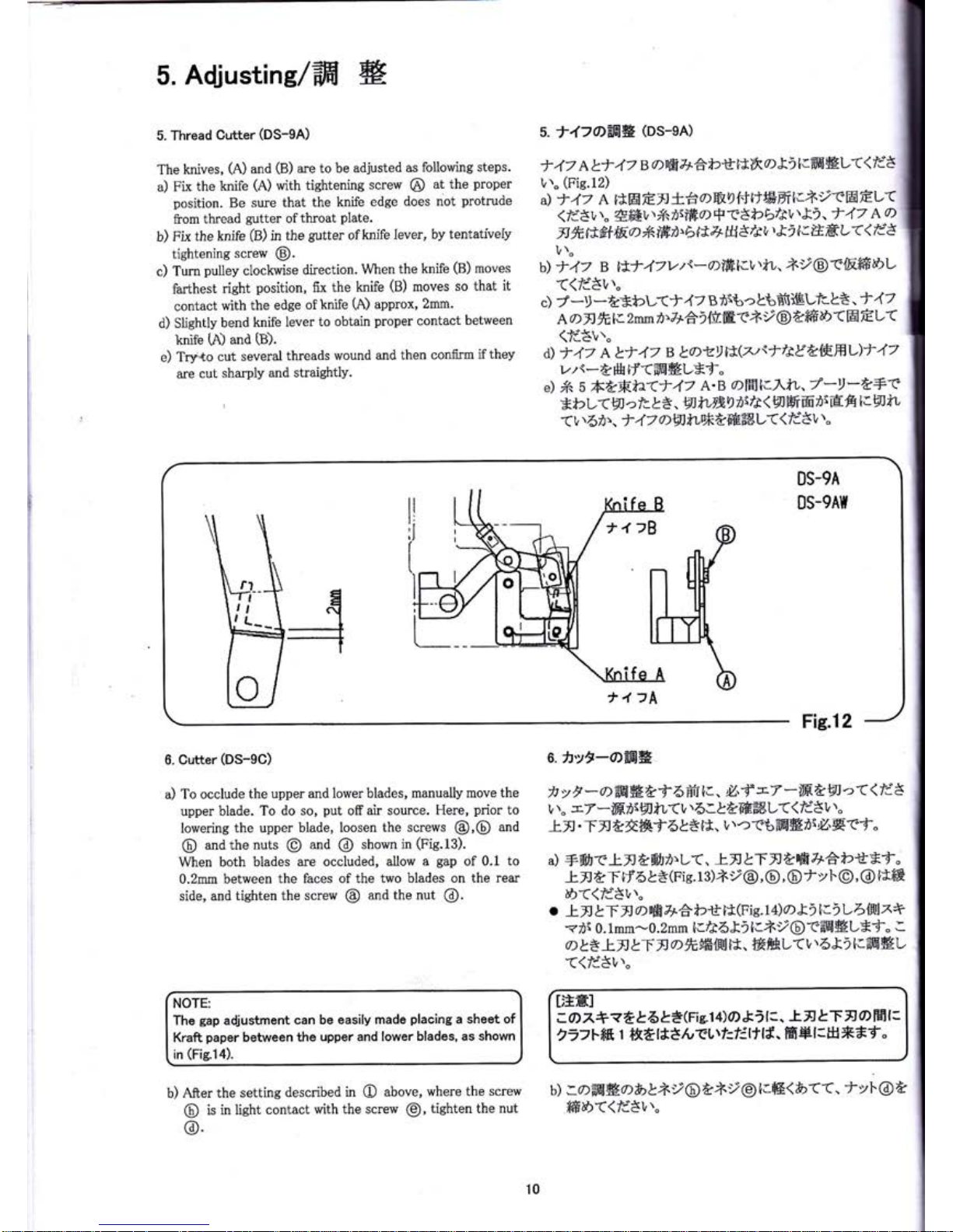
The
knives,
(A)
and
(B)
are to
be adjusted
as following
steps.
a)
pix
the
knife
(A)
with
tightening
scre\4r
@
at the
proper
position.
Be
sure that
the knife
edge
does not
protrude
from
thread
gutter
ofthroat
Plate.
b)
Fix
the knife
(B)
in
the
gutter
ofknife
lever,
bv
tentativelv
tightening
screw
@.
c) Tum
pulley
clockwise
direction.
When
the knife
(B)
moves
farthest
right
position,
fix
the knife
(B)
moves
so that
it
contact
with
the
edge
of
knife
L\)
approx,
2mm.
d) Sliehtly
bend
knife
lever
to obtain
proper
contact
between
knife
(A)
and
(D.
e)
Tr:nto
cut
several
threads wound
and then confirm
ifthey
are cut
sharply and
straightly.
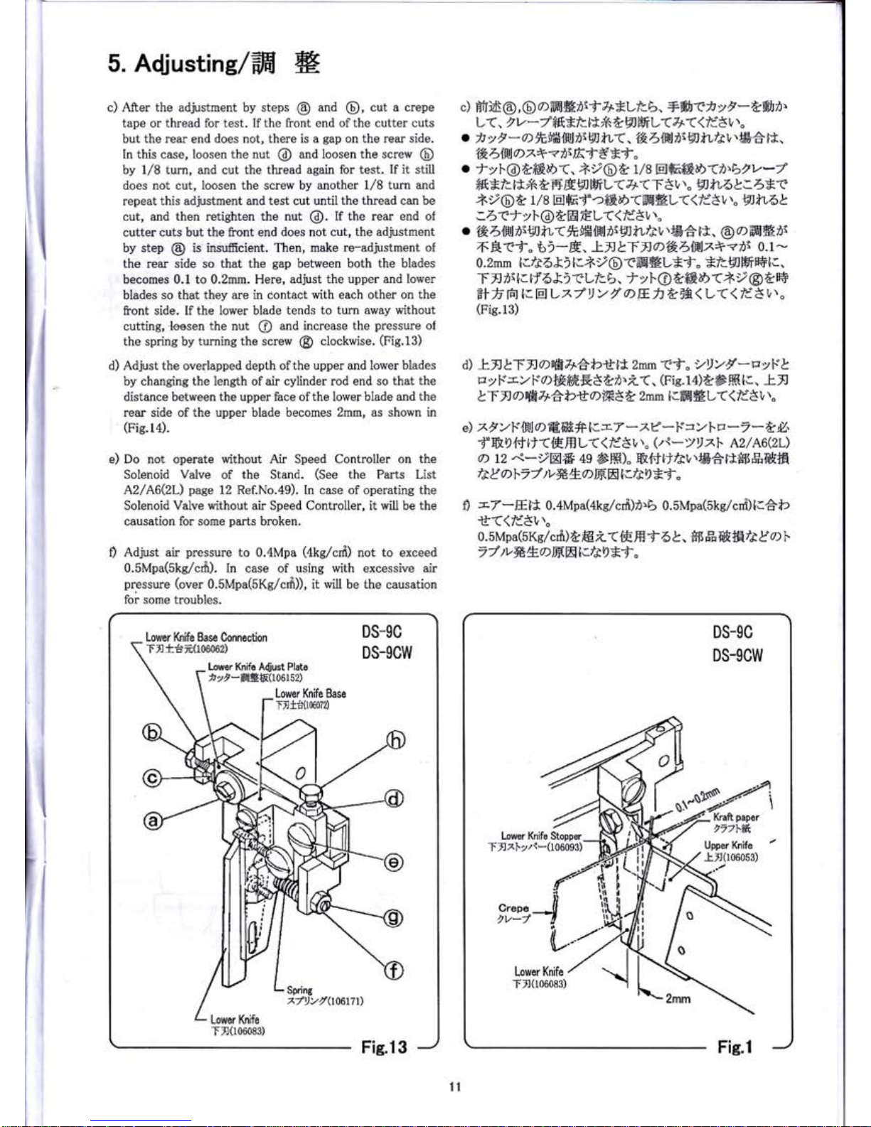
6. Cutter
(DS-9C)
a) To
occlude
the upper and
lower blades, manually
move
the
upper
blade. To
do so,
put
off air
source. Here,
prior
to
lowering
the upper blade,
loosen the
screws
@,@
and
@
andthenuts
@
and
@
shownh(fie.tf).
When
both blades
are oecluded,
allow
a
gap
of
0.1 to
0.2mm between
the faces of the
two blades on the
rear
side, andtighten
the
screw
@
and the nut
@.
b) After
the
setting
described
in
O
above,
where the
screw
@
is
in light contact
with the screw
@,
tighten the
nut
@.
u*.,a1
;a 7+v
t&
6
&*(Fie.1
4)O
&5
l:,
-E.n
&T 5
o
Fe3
l:
,a7F*fr,
I
tfEl*t/-(Ltf:Elt{f,.
ffi+t:H*tf
"
NOTE:
The
gap
a{ustment
can be
easily made
placing
a
sheet of
Kraft,
paper
between
the
upper and lower
blades, as shown
in
(Fig.14).
10
5. Adiustins/ffi
W
c) After the adjustment by steps
@
and
@,
cut a crepe
tape or thread for
test.
Ifthe
front
end
ofthe cutter cuts
but
the
rear end
does
not,
there is a
gap
on the rear
side.
In this case, loosen
the
nut
@
and loosen the screw
@
by l/8 turn, and
cut
the thread
again for test. If it still
does
not
cut,
loosen the screw by another 1/8
turn and
repeat
this adjustment and test cut until
the thread
can
be
cut, and then retighten the nut
@.
If
the
rear end of
cutter cuts but the front end does not cut,
the adjustment
by step @ is insufrcient. Then, make
re-adjustment of
the rear side so that the
gap
between both the blades
becomes 0.1 to 0.2mm. Here,
adjust the upper
and lower
blades so that they
are in contact
with
each other
on the
front side. If the lower blade
tends to turn
away without
cutting,
lsesen
the
nut
@
and increase the
pressure
of
the spring by turning
the screw @ clockwise.
(p'is.t3)
a) eajust the
overlapped
depth ofthe upper and lower blades
by changing the leneth ofair cylinder
rod end so that
the
distance between the upper face ofthe lower blade and
the
rear side of the upper blade becomes 2mm, as shown
in
(Pis.t+).
e) Do not operate without Air Speed Controller
on the
Solenoid Valve
of
the
Stand.
(See
the Parts List
A2/A6(2L)
pace
12 Ref.No.49). In case of operating
the
Solenoid Valve
without air
Speed Controller, it will be the
causation
for some
parts
broken.
0
eajust air
pressure
to 0.4Mpa
(ake/cfi)
not to exeeed
0.5Mpa(5kg/crf,).
in case of using with excessive
air
pressure
(over
0.5Mpa(5Kc/crfi)),
it
will
be the
causation
for some
troubles.
c)
Bfrs@,
@
rr-ffiWrt\f 7^*Lt6.
*qt1)t v
I
-t#9'
L<.,
v
*j*.fi*r..i**
&
\JWL<
7r<(
fd8
t,''.
.
fi
y
F
-
aft
'ffi
fiil
rlq
fu
<
.,tr4[ilrt\
@
il"ttv).E6 t*
-
,tk4l1lD^+?r\Efg*f.
o
fvl-@ &ffiE.<.
jir@
A
U
I
@*ffiE.art,b2v*7
*rG)
a
1/8
EEf,
fi*b<ffi#t-((td3
v',"
qttL6
t.
:,5<iyl.@AEEL(<fd8L
\"
.'&
6lillrt\gJ
tL<
fi,iHlillrti fl
fu
/3 t,
r
S.S
it.
@
a>
ffi
#
rr
6Rrf" 6
i-8.
.tIJ
LT
fl
a'rkbl\lT*<ri 0.1
-
0.2mm
tc/r5E5 O.*y@rAB#L*f"
*tc.9llfiffiic.
T>l
rr
[.
if
6&irLlc b. t vl
@
tftED
<+r@
&H
A+frfilttr4r7aY
Ytr DEh
Arf;<
L(( /dE
t,''.
(Fis.13)
d)
-trg&fIJ
arffi&eb:&i* 2mm
<t"
yy>.y
-pyr.^&
r:
y
5^-7f."d) t*ffiF.5?rt.Z(.
(Fig.
1 4)t
>ffil.,
-Lfl
LT
rJ
Dffi46i2tol#3
t
2mm
(cffi
#u<</i8v
t"
d
^,
vF
[H\o €ffi #
ic-7
-^c
*
i.^
av
Fv
-
7
*
t il,
f
mD{.f
[r<&ffi
L(<
fjg
1
r.
(z{
-yt)
z.l_
Az
/
A6(ZL)
a n
*-rEl6
+g
aK)"Wttt]lrv.#6Effi$tfiEH
ft
E
o>
17
7
tv
#
/fa'lilW.tr9
*f
"
0
-7-E
lt
o.4Mpa(4ks/crf)t.b 0. 5Mpa(5ks/cni)
trAt:
il(<fi8L\"
0.5Mpa(5Ke/ crk)t
ffiL<{E,ffi
f
6
}.
S
ft
fift H
/r
Do l.
7)turyhogEI[:699j"
Lower Knife
Base
Connection
Tnt6i(106062)
Kraft
paper
,77\ffi
Lower Knife Stopper
Tnxl.y/{-(106093)
11
 Loading...