

NEWLONG
MODEL
DS-10^^
PRESSURIZED
MACHINE
Fi
if
INSTRUCTION
/•y
FISCHBEIN
MNUAL/PARTS
looooj
MODEL
DS-10A
•S-1
LIST
O C
§
L.
ty
/ I
NEWLONG
MACHINE
WORKS.
No.n
LTD
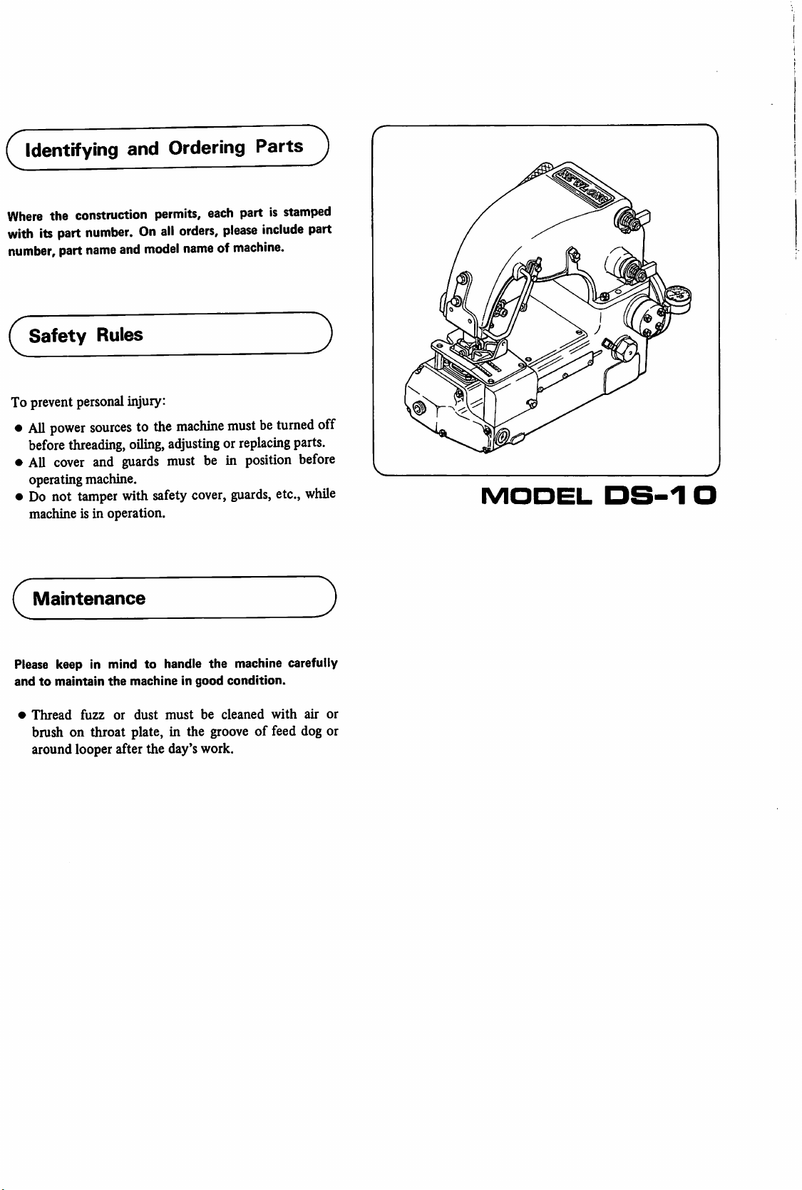
Identifying and Ordering
Where
the construction permits, each part is
with
itspart
number,
number.Onall
part
name
and
orders,
model
nameofmachine.
please
Parts
stamped
include
part
Safety
To prevent personalinjury:
•
All
power
beforethreading,
•
AU
cover
operating machine.
•
Do
not
machine is in operation.
Maintenance
Please keep in mind
andtomaintain
•
Thread
brush on throat plate, in the
around looper after the day's work.
Rules
sourcestothe
oiling,
and
guards
tamper
fuzz
with
the
machineingood
or
dust
machine
adjusting or
must be in
safety
to
handle
must
mustbeturned
cover,
guards,
the
condition.
be
cleaned
groove
off
replacing
position
machine carefully
parts.
before
etc.,
while
with
air
of feed dog or
1
MODEL
or
DS-1
O
CONTENTS
1. INSTALLATION 2
1—1
Motor
Recommendations
1—2 Initial Lubrication 2
2.
MAINTENANCE
2-1
Oil 2
2-2
Seals 2
2—3
Cleaning
2—4 ColdAreaOperation 3
2—5 RunningAfter Prolonged Shot-Down 3
2—6
Threading
2
2
2
3
2—7 Tensions 4
2—8
2—9 Stitch Length 4
2-10
2—11 Looper 4
3.
TROUBLE
3—1
Needle
Replacement
Needle
Thread
2—12 Looper Holder 4
2—13
Needle
Guard
2—14 Presser Foot Spring Pressure 5
2—15
Feed
Dog
SHOOTER
Pull-Off 4
Height
Synchronization
4
5
5
5
5
3-2
3—3
Oil 5
Thread
3—4
FailureToChain
3—5
Uneven
3—6
Excessive
BreakageOrSkipping
Off
After
BagIsSewn
Stitch
LengthOrPoor
Needle
Breakage
Stitches
Feeding
- 1 -
5
5
5
5
1.
INSTALLATION
1—1
Use a 0.75
(1420
sewing
pulley
1
Motor
RJ*.M.
Recommendations
KW
(1/2 HP) 1725 R.PJ^. (60 Hz) motor
for 50 Hz). The variable pulley on the
head permits speed adjustment.
must
rotate
clockwise.
—2
Initial
Lubrication
Sewing
head
The sewing head is shipped from the factory oil filled.
2.
MAINTENANCE
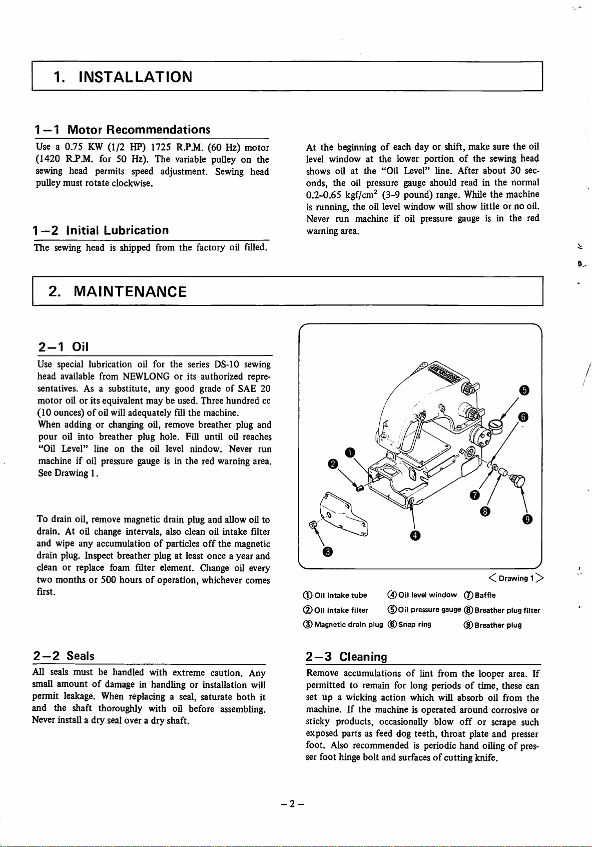
2-1
Use special lubrication oil for the series DS-10 sewing
head available from NEWLONG or its authorized repre
sentatives. As a substitute, any good gradeofSAE 20
motor oil or its equivalent may be used. Three hundred cc
(10 ounces)
When adding or changing oil, remove breather plug and
pour oil into breather plug hole. Fill until oil reaches
"Oil
Oil
Level"
of
oil will adequately fill the machine.
line
on
the
oil
level
nindow.
Never
machine if oil pressure gauge is in the red warning area.
See Drawing 1.
run
At the beginning of each day or shift, make sure the oil
level window at the lower portion of the sewing head
shows
oilatthe
"Oil
Level"
line.
After
about
30
sec
onds, the oil pressure gauge should read in the normal
0.2-0.65
kgf/cm^
(3-9
pound)
range.
While
the
machine
is running, the oil levelwindow will show little or no oil.
Never run machine if oil pressure gauge is in the red
waming
area.
To drain oil, remove magnetic drain plug and allow oil to
drain. At oil change intervals, also clean oil intake filter
and wipe any accumulationofparticles
off
the magnetic
drain plug. Inspect breather plug at least once a year and
clean or replace foam filter element. Change oil every
two months or 500 hoursofoperation, whichever comes
first.
2—2
All
small amountofdamage
Seals
seals
must be handled with extreme caution. Any
in handling or installation will
permit leakage. When replacing a seal, saturate both it
and the shaft thoroughly with oil before
Never install a dry seal over a dry shaft.
assembling.
(D Oilintake tube 0)01!
0
Oil
intake
filter
0 Magneticdrain plug (jDSnap ring
2—3
Cleaning
(DOil
level
window0Baffle
pressure
gauge
(g)
Breather
(D Breather plug
Remove accumulationsoflint from the looper area. If
permitted to remain for long periodsoftime, these can
set
up
a wicking
action
which
will
absorb
machine.Ifthe machine is operated around corrosive or
sticky products, occasionally blow
off
or scrape such
exposed parts as feed dog teeth, throat plate and presser
foot.
Also
recommended is periodic hand
ser foot hingebolt and surfacesof cutting knife.
-2-
<C
oil
oiling
Drawing
plug
from
of pres
1^
filter
the

2—4
In very cold areas allow machine to warm up by miming
steadily for a
ure to do this,
phase
the
the speed of the
badly scuff tape and
sewing
Cold
current,
sewing
headand motor
Area
few
can
head. This
Operation
minutesbefore
especially
with units mnning on
resultinslow
causes
conveyor
cause
warm
closing
starting
mis-synchronization with
belt which
sewing
up and attain proper
any
and
will
break thread,
problems
bags.
mnning
Fail
single
until the
speed.
of
2—BiRunnlng
After
prolonged
should be
motor
accomplished
second cycles until the oil pressure gauge reads in the
normal
pumping
warmed
0.2-0.65
After
shut-down
up before
by mnning the
kgf/cm^
Prolonged
properly and the
closing
(3-9
periods,
any bag. This is
sewing
pound)
Shut-Down
the
sewing
sewing
head in short 2-3
range.
head oil
head and
easily
2—6
Follow the threading diagram below for proper thread
ing.
the
Threading
Be sure looper thread
looper.
Threading
passes
through both holesof
Diagram
Needle
Looper
Thread
Thread
CD
Needle
lever
tension
assembly(DNeedle
thread
pull-off
(3)
-3
Needle
thread
-
tension
(4)
Looper
thread
tension
<C.Drawing
2^
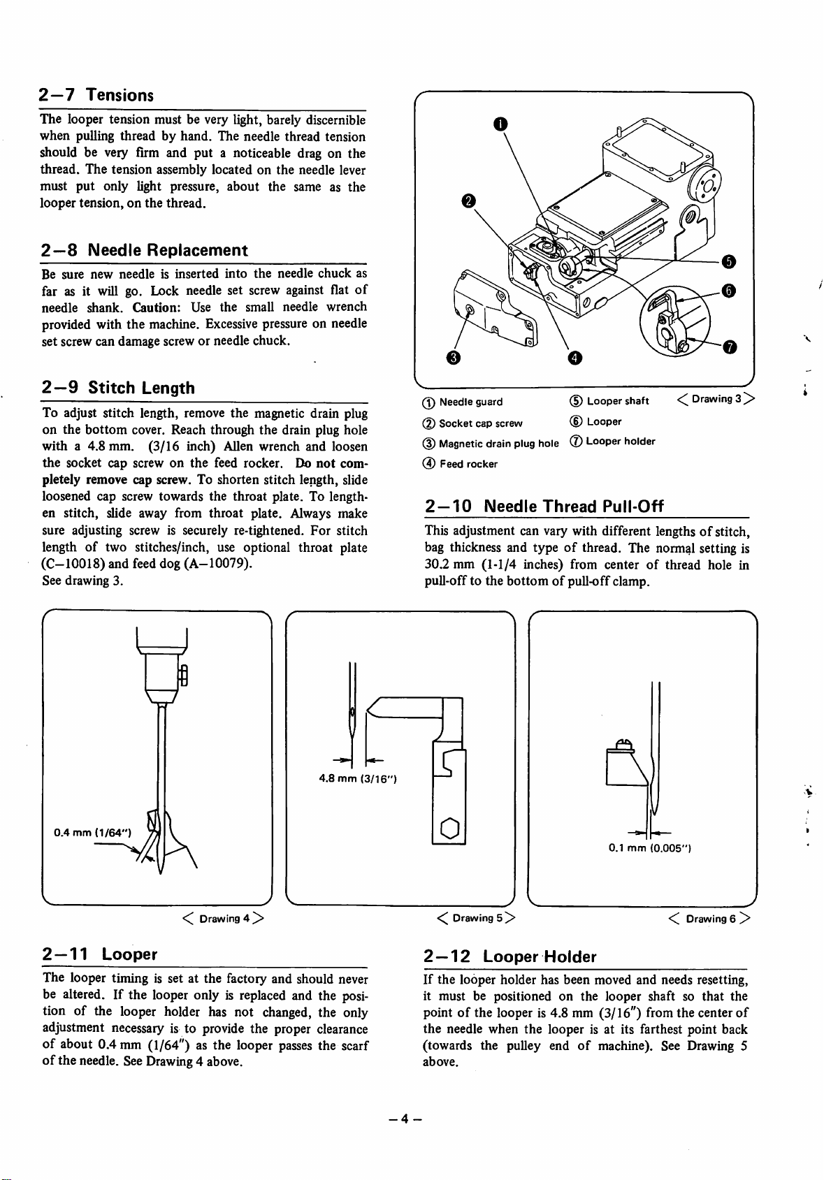
2—7
The looper tension must be very light, barely discernible
when pulling thread by hand. The needle thread tension
Tensions
should be very firm and put a noticeable drag on the
thread. The tension assembly located on
must
put
looper
only light pressure,
tension,onthe
thread.
about
the
the
needle lever
same as
the
§
2—8
Be
sure
Needle
new
needleisinserted
Replacement
into
the
needle
chuck
far as it will go. Lock needle set screw against flat
needle
provided with the machine.
set screw can damage screw or needle chuck.
2—9
To adjust stitch length, remove the magnetic drain plug
on the
with a 4.8 mm. (3/16 inch) Allen wrench and loosen
the
pletely remove cap screw. To shorten stitch length, slide
loosened cap screw towards the throat plate. To length
en stitch, slide away from
sure adjusting screw is securely re-tightened. For stitch
shank.
Stitch
bottom
socket cap screwonthe
Caution:
Use
Length
cover. Reach through the drain plug hole
the
small
Excessive
feed rocker. Do
throat
pressure on needle
plate. Always make
needle
wrench
not
com
length of two stitches/inch, use optional throat plate
(C-10018)
See drawing 3.
and feed dog (A-10079).
as
of
(1)
Needle
(2)
Socket
(3)
Magnetic
(4)
Feed
guard
cap
drain
rocker
screw
plug
hole
(§)
(D
(l)
Looper
Looper
Looper
shaft
holder
Drawing
3^
2—10 NeedleThread Pull-Off
This adjustment can vary with different lengthsofstitch,
bag thickness and typeofthread. The normal setting is
of
30.2 mm (1-1/4 inches) from center
pull-off to the bottomofpull-off clamp.
thread hole in
4.8
mm
0.4
mm
2 —
11
Drawing
Looper
4 ^
The looper timing is set at the factory and should never
be altered. If the looper only is
tion of the looper holder has not
replaced
changed,
and the posi
the only
adjustment necessary is to provide the proper clearance
of about 0.4 mm (1/64") as the looper
of
the needle. See Drawing 4 above.
passes
the scarf
(3/16")
1
0
0.1
mm
(0.005")
Drawing
2 —
12
If
the
it must be positioned on the looper shaft so
point of the looper is4.8 mm (3/16") fromthe centerof
the needle when the looper is at its farthest point back
(towards the pulley end
above.
-4-
5]>
Looper
looper holder has been moved and needs resetting,
Holder
of
machine). See Drawing 5
Drawing
that
6 ^
the
2—13
The
If it is
should be set so that the needle clears it by about
0.1 mm (0.005"). See
2 —
To adjust the presser foot spring pressure, turn the hex
adjusting screw on
screw clockwise will increase
wise will decrease pressure. The pressure has been set at
the factory at about 18 kg (40 pounds),-which should be
adequate for most purposes.
3.
3—1
The
or belt. A model
10~15%
used,
Needle
needle
guard
is stationary and
14
replaced
Presser
due to
TROUBLE
Synchronization
sewing
head
mustbe
faster
thanthe
it must
also
Guard
needs
no adjustment.
excessive
wear or
damage,
Drawing6above.
Foot
topofthe lever housing. Turning the
Spring
the
Pressure
pressure, counter-clock
SHOOTER
synchronized
DS-10
sewing
conveyor.
be synchronized with the
withthe
convey
head should run about
If a
power
top
feed
conveyor.
is
All conveyor models are properly synchronized at the
factory,
customers plantmight makeminoradjustment
3-2
1. Check oil daily. Do
2. At oil change intervals, remove
but
differencesinvoltage
between
factory
and
necessary.
Oil
not
allow machine to
oil pressure gauge needle does
red zone
clean, or if necessary, replace intake filter. See Page
2.
while
machine isrunning, stop immediately.
not
bottom
run
low.
remain above the
cover and
If
2 —
15
Feed
it
Theteethofthe
above
the
height adjustmentofthe feed dog should be necessary
when replacing it. However, if the dog has been re-sharp
ened or is being raised to compensate for worn teeth
recommended procedures), it will be necessary to loosen
the
feed dog carrier rod clamp and raise
Dog
Height
feed
dog
should
protrude1.6mm(1/16")
throat
plate when at their highest point. No
the
feed dog car
(not
rier rod to restore the proper 1.6mm(1/16") heightof
the feed dog teeth above the throat plate. Be sure to align
the feed dog properly in the slots of the throat plate be
fore securely locking
5.
Replace
6. Check conditionoflooper.Ifit is rough or has some
nicks, replace it. See Page 4.
7. Check conditionofthroat plate. If it is rough or has
nicks, replace it.
8. Check sharpnessoffeed dog.Ifdull, replace it. Note:
Only the outside rowsofteeth should be sharp. Do
not
3—4
1. Check items listed
2. Check presser foot pressure. It should be approxi
mately 18 kg (40 pounds). See Page5.
needle.
sharpen center teeth.
FailureToChain
the
feed dog carrier rod.
See
Page
4.
Off
under
thread
After
Bag Is
breakage above.
Sewn
3. Remove accumulationsoflint and dirt from looper
area. If permitted to remain for long periodsoftime,
these can set up a wicking
oil
from
the
machine.
3—3
Thread
Breakage Or
1. Check to be sure nothing is interfering with the
passage
needle and looper.
2. Check to see that both needle and looper are thread
ed properly. See Drawing 2.Ifeither are threaded
improperly,itcould
Use
the
of the thread from the cone allthe wayto the
cause
the
tweezers supplied
top
(or back) endoflooper.
3. Check the needlethread pull-off. See
doubled
over,
addabout3.2 mm(1/8").
4. Checktensionofboth threads. See
action
Skipping
the
needle
with
the
which will absorb
Stitches
free
threadtobreak.
machine to thread
Page
4. If bagis
Page
4.
-5
3—5
Uneven
Check sharpnessoffeed dog and presser foot pressure.
Excessive
3—6
1. Operator may be pulling bag through machine.
2. Sewing may be
3. Check alignmentofneedle slot in presser foot to be
sure
needle
4. Check to see
sideofmachine.
5. Check sharpnessoffeed dog.
6. Check synchronization.
-
Stitch
Needle
too
does
that
LengthOrPoor
Breakage
close to
not
the
contentsofbag.
rub.
needle chuck is parallel
Feeding
with

Memo

ORDERING
(1)
«Rp"p«liDS-l
g|5p°n^rttS:wKU.
(2)
mi£:S:<nmi,
(3)
ISLH#
(1)
Descriptionofeach
parts list.
parts.
nameofpart.
(Ref. No.) WEAA'i:v>gBp'?.(i,
Screws
When
ordering
(2) Part that has no Ref.
always
order
it as an assembly.
(3)
This
part
list
(refer to columnofQuantity.)
^ Information included in this part list is subject to change without
prior
notice.
OA,
DS-10C«^«Sr*fflL*t<7)-C-,
S#p°#-t.
part
and
its
and nuts for parts are
parts,
describe
Number
covers
parts
of not
gRo°«lii-..
<
^wti
stamp
numberisdescribedinthis
shown
clearly
can not be
only
DS—lOA
fflSc4:WeT#t>,
ztti't)
adjacentto the relevant
stamp number with its
delivered
PARTS
#«:8S^t-§
nit.
independently;
but
also
DS—IOC.
CONTENTS
a
-k
01 Tape Clipper 8
02
Oil
Pump&Counterweight
03
Main Housing 14
04
Lever Housing 18
Assembly 12
05 Needle & Presser Foot LeverAssemblies 20
06
Feed
07
Assembly
ji'J
Main
Shaft&Knife
Assembly
24
26
08
Looper
;u—
Assembly
Numerical IndexofParts 29
-7-
28

01
TAPE
CLIPPER
PARTS
CD
CD
33
29
fa.
-8-
01
Ref.
El#
TAPE
No.
CLIPPER
ni^qq##
Part
No.
PARTS
nBqq^$5^
Description
@
litQ'ty
DS-IOC
Remarks
20
21
22
24
26
27
28
10
11
12
13
14
15
16
17
18
19
23
25
29
30
31
32
33
34
35
36
37
38
39
40
41
42
43
44
1
2
3
4
5
6
7
8
9
P-10423
T-3129
A-10424
A-10421
SC14201-L
A-10422
P-10420
SSI032316
A-10419
A-10404
A-10414
A-10437
A-10415
A-10412
P-10413
H103212
NH1428
A-10440
WN14
A-10430
A-10429
A-10023
A-10425
A-10092
P-10438
H103258
A-10405
A-10406
P-10409
A-10407
P-10408
A-10410
P-10411
D07025
705021
D07026
705031
A-10403
F103212
A-10443
B-10432
SC1420114
P-10125
A-10426
Pin, pivot
Washer,
Spring, compression
Lever,
Screw, socket cap
link,
Ring,
Screw,
Crankshaft
Assembly,
Rod, connecting-piston
Washer, rod-connecting
Pin,
Piston
Ring,
Screw,
Nut,
thrust
drive-cutter
drive-cutter
"0"-crankshaft
set
crank
wrist
piston
hex
HD
hex
yj
V
if
fi
-y
K
ii
y
Vi;
" 0 " V V
9 =7 V ^
y i; V ip =7 y 9
t'
b V P .y K
7 .y •> + —
b V
'7
" X " V ^
b
y b
Y
Screw, adjusting
Washer,
nylon
Plate, cover
Gasket
Insert thread-lever shaft bushing
Bushing
Gasket, cover-top
P V 7 .y V' + —
7 ^
if
^'r
y b
7.
y y V y
•T'i
7-7-^7
My—
b7'.y-73.
b )
Washer, compression 4
Screw,
hex
HD
Housing,
Washer,
Ring,
Plate,
Ring,
cutter
head
cylinder
"0"-cylinder
bumper
bumper
Head, cylinder
Ring, snap
Elbow,
street
Pipe
Elbow,
female
Pipe
Assembly, seal-shaft
Screw,
Knife,
flat
HD
moving
Lever, knife
head
•7
7 ^
" 0 " V y y
" G " y 7 y
•7 V
it.
:x./V
ii
mW}7^
y^
b
i; 1
y—
y^
.y
b*
^
7°
PC-
—
y
'y
7
Screw, socket cap
y7
Plug, pipe-mainshaft
Shaft,
knife
y
y-f7 7 7 b
1
2
1
1
1
1
2
1
1
1
2
4
2
2
2
8
1
1
1
1
2
2
2
1
4
2
2
2
2
2
2
2
1
2
1
1
2
2
1
2
1
1
-9-

01
TAPE
x—^
CLIPPER
PARTS
OCt)
29
-10-

01
Ref.
TAPE
No.
CLIPPER
Part
No.
PARTS
Description
m IgcQ'ty
DS-IOC
Remarks
45
46
47
48
49
P-10428
A-10427
SSI032316
WN8
B103214
Washer,
Shaft,
Screw,
thrust
thrust
socket
set
Washer, nylon
Screw, binding HD
t*
V
P y 7 .y + —
1
1
4
4
4
-11
-

02
OIL
PUMP
&
COUNTERWEIGHT
ASSEMBLY
PARTS
-^x-f
h/<7VXSaiBII#
A
\ 1 24 23
26
9
-12-

02
OIL
PUMP
&
COUNTERWEIGHT
ASSEMBLY
PARTS
Ref.
m #
10
11
12
13
14
15
16
17
18
19
20
21
22
23
24
25
26
27
28
29
30
31
32
33
34
35
No.
1
2
3
4
5
6
7
8
9
Part
No.
A-10191
P-10192
A-10204
B103212
WN8
NJIO
A-10105
P-10107
SC63278
A-10178
P-10104
A-10103
A-10061
SS142038
SS142038CP
A-10101
A-10102
SS1032316
A-10106
NH1420
P-10107
A-10169
P-10051
A-10130
A-10053
P-10084
B-10167
HI03212
A-10168
A-10049
B-10050
H1032114
H10321
A-10127
A-10052
Description
Ass'y,
filter-intake
Ring,
Retainer,
"0"-intake
tube-intake
filter
7^
0 " V V
Screw, binding HD
Washer,
Nut
Ass'y,
Ring,
Screw,
Insert,
Link
Pin, pivot-pump drive V y
Eccentric,
Counterweight &
Link,
Ass'y,
Nut,
Ring,
Piston, pump
Ball, valve
Spring, relief-oil pressure
Plug, spring-valve
Ring,
Body,
Screw,
Cyhnder,
Gasket, block-valve
Block,
Screw, hex HD (long)
Screw, hex HD (short)
Spring, block-valve
Seal, washer-valve
nylon
^ V 7 y-y^ —
y V 1
tube-intake
"0"-intake
socket
body-pump
connecting-pump
Screw,
set
Screw, set-cone
control-pump
Screw,
set
tube
HD cap
stroke-pump
point
Pump
drive
drive
Drive
0"v
V^
-•t;
yy't)
y —
V V ^
if
\L y
y y ^ ^ b 1 1
tube-pressure 1 1
hex
"0"-tube
"0"
pump
hex
pump
valve
terminal
HD
plug
.y b
" 0 " •; V ^
h y
-/u
C )
v>5'*(y
y'y^
" 0 " V y
7i-:yy°:^i$.
V y -
jivy—
A/vy'%^
•'^/uy
yy'
o y 7
y-7>'vuy)
b
b
b
b
V y
.y-yj^~
y'
@ ^
DS-lOA
1
1
1 1
1
1
1
1
1 1
1
1 1
1 1
1
1
1
1
1 1
1 1
1
1 1
1 1
2 2
1 1
2 2
2 2
Q'ty
DS-IOC
1
1
1
1
1
1
1
2
2
2
1
1
2
1
2
1
3
1
3
2
1
Remarks
(14,15)
(18)
-13-

eo
niviai
0NisnoH
siavd
OOl-SQ
^
/•
Tl>^
^
-Wyi
301-sa

03
m #
Ref.
MAIN
No,
1
2
3
4
5
6
7
8
9
10
11
12
13
14
15
16
17
18
19
20
21
22
23
24
25
26
27
28
29
30
31
32
33
34
35
36
37
38
39
40
41
42
43
44
45
HOUSING
Part
No.
C-10017
C-10018
F103258
F103238
A-10091
F83214
A-10015
H103212
WN8
D208
B103214
WN8
P-10111
B-10022
F1032114
F103258
A-10170
NH1420
WF14
WN14
A-10093
A-10016
H103212
WN8
D208
A-10005
A-10021
F63234
A-10019
A-10020
D05003
A-10097
H103212
D208
A-10098
B632316
A-10164
H103234
A-10134
A-10179
A-10116
A-10121
P-10227
P-10226
H10321
A-10094
PARTS
Description
Plate,
throat
Plate,throat(Long Stitch)
Screw, flat HD (long)
Screw, flat HD (short)
Knife, stationary
Screw,
flat HD
Post,
short-throat plate
Screw,
hex
HD
Washer, nylon
Washer
Screw, binding HD
Washer
Plug, drain-magnetic K U V 7° 7
Cover,
bottom
Screw, flat HD (long)
Screw, flat HD (short)
Pull-Off-Looper Thread
Nut,
hex
Washer
Washer-Nylon
Gasket,
cover-bottom
Post, long-throat plate
Screw,
hex
HD
Washer-Nylon
Washer
Door, looper
Knob,
latch-looper
door
Screw, flat HD
Spring, latch-looper
door
Latch, door-looper
Window,
Plate, latch-looper
Screw,
Washer
oil level
hex
door
HD
Cover, groove-thread
Screw, binding HD
Eyelet,
Screw,
thread-short
hex
HD
Ring, snap-breather baffle retainer
Baffle, plug-breather
Ass'y, plug-breather
Filter,
plug-breather
Gauge, oil pressure 1
Adapter,
Screw,
Gasket,
gauge-oil pressure
hex
HD
main
shaft
seal
(
•>'
3 - b )
h
i-'i
n V 7 y -y —
P V 7 .y -v —
K
^ P V 7 .y V' —
/Uv'—
h )
P
77*
p V 7 .y •> -t- —
/U
— —
/ 7*
7.y'V V
7
^
7'
.y^
jL7
¥J^^
K
(/Jn)
h
7. .y 7* V y
7-7'
y
7 ^/u7 -
7
7'7*7-
/I'-y—
V
)
if
0
DS-lOA
1
(1)
1
1
1
1 1
1
1
1
1
1
1
1
1
1 1
1 1
1
1
1
1
1
1
1
1
1 1
1 1
1
1
1
1
1 1
1 1
1
1 1
1
1 1
4 4
1
Wl
Q'ty
DS-IOC
—
-
1
2
—
—
—
1
1
2
2
1
1
2
4
1
1
1
1
1
1
1
—
—
—
—
—
1
1
1
1
1
1
1
1
m m
Remarks
Special Order
(1#^)
-15-

03
MAIN
HOUSING
PARTS
DS-IOC
DS-IOC
-16-

03
Ref.
MAIN
No.
HOUSING
Part
No.
PARTS
Description
DS-lOA
15:
Q'ty
DS-IOC
Remarks
46
47
48
49
50
51
52
53
54
55
56
57
58
59
D-lOOOl
A-10095
A-lOlOO
H103212
A-10092
A-10014
F103238
B-10485
B103214
A-10449
F83212
A-10446
A-10434
NH832
Housing,
main
Gasket, cover-manifold
Cover,
manifold
Screw,
hex
HD
Gasket, cover-top
Plate, cover-top
Screw, flat HD
Plate,
throat
Screw, binding HD
Fence
Screw, flat HD
Knife,
bed
Post,
offset
Nut,
hex
.y K
^
/U-y— h
-V — — /U K ^
i-
y h
-17-

04
LEVERS
HOUSING
PARTS
-18-

04
LEVERS
HOUSING
PARTS
Ref.
m#
S^Q'ty
No.
1
2
3
4
5
6
7
8
9
10
11
12
13
14
15
16
17
18
19
20
21
22
23
24
25
26
27
28
29
30
31
32
33
34
35
36
37
38
39
40
41
42
43
Part
A-10142
A-10161
H103278
WFIO
A-10188
SS1032516
B-10123
B103238
A-10146
P-10013
B-10145
HI03234
1-178
A-10144
A-10171
A-10172
HI03234
A-10164
HI03234
NH1428L
A-10114
A-10008
A-10120
A-10007
A-10115
D-120
P-10010
A-10165
HI03234
H3824134
WF38
D-10002
SC516181
WS516
A-10143
SS142038
SC5161858
A-10187
A-10186
A-10139
SS142014
B-10141
SC142034
No.
Description
Cam, lifter-presser
foot
Guide, lever-presser foot
Screw,
hex
HD
Washer
Guard,
Screw,
tension-needle
set
Cover, guard-levers
Screw, binding HD
Plate, presser foot spring-tapped
Pin,
roll
Spring, presser foot
Screw,
hex
HD h
Nut,
lock
Clamp, spring-presser foot
Pull-off, needle thread
Clamp, needle thread pull-off
Screw, hex HD
Eyelet,
Screw,
Nut
Sleeve,
thread-short
hex
HD
tension
Spring, tension-looper thread
Disc, tension-large
Spring, tension-needle
Stud,
tension
Washer,
lock
thread
Pin, retaining-tension disc
Eyelet, thread-long
Screw,
hex
HD
Screw, adjusting
Washer
Housing, levers
Screw,
socket
HD cap
Washer, spring
Shaft, spring-presser
Screw,
set
Screw,
stop-lifter
foot
lever
Spring, lifter lever
Liner, bushing-lifter lever
Bushing, lifter-presser
Screw,
set
Lever,
lifter-presser
Screw,
socket
HD cap
foot
foot
K
7 — A —
7.7°
7ti
b
4 K
(/J^)
b
p V .y b
X U -
7'
7.
7° V y 7" t* 7
K
b 4
b
r-M.
7.7'U V 7* 7
y
y—
y—zv
A
-f K
(T^)
y
'J 7
'J
J'
b
b
7'
vi/
y
if
DS-lOA
DS-IOC
1
1
2
2
1
2
1
2
1
1
5
2
2
1
1
1
2
1
1
2
4
1
4
1
2
2
2
2
1
1
1
4
4
1
1
1
1
1
1
1
1
1
m g
Remarks
(43)
-19-

05
NEEDLE
&
PRESSER
FOOT
LEVER
ASSEMBLIES
PARTS
58
-20-

05
NEEDLE
&
PRESSER
FOOT
LEVER
ASSEMBLIES
PARTS
Ref.
m#
23
24
25
26
27
28
29
30
31
32
33
34
35
36
37
38
39
40
41
42
43
44
45
@ ^ Q'ty
No.
1
2
3
4
5
6
7
8
9
10
11
12
13
14
15
16
17
18
19
20
21
22
Part
A-10031
H103234
NJIO
C-IOO-S
A-10011
A-10212
A-10211
SC63234
A-10166
F54038
A-10119
A-10009
A-10181
B632316
A-10231
H103212
A-10232
A-10113
A-10023
A-10025
SS1032316
SS103238
T3129
C-10003
SC1420114
A-10026
B-10137
F103238
A-10128
A-10028
A-10159
B-10047
SS142038CP
SS142014
HI03238
WSIO
A-10048
F103238
C-10004
SC1420114
A-10189
F63212
P-10193
A-10190
A-10163
No,
Description
Chuck, needle
Screw,
hex
HD
Nut,
hex
HD
Needle
Screw, clamp-needle
tf
tfjlr.
y h
^
Plug,clamp-tapped (needlelever) ^ V B )
y
Plug,clampdrilled(needlelever)
Screw, socket HD cap
V7*(
h
Guide, thread-needle lever
Screw, flat HD
Disc.,
tension-small
Spring, tension-needle lever
Collar,
tension-needle
lever
Screw, binding HD
Washer, heavy-needle lever
Screw,
hex
HD
Rod,
clamp-needle lever
Stud,
tension-needle
lever
^ 7 V y P .y K
Insert, thread-levers shaft bushing
Bushing, shaft-levers
-y 7 h
7*.y
Screw, set (short)
Screw, set (long)
Washer,
Lever,
thrust
needle
Screw, socket HD cap
Shaft,
levers
1/^N
— •y' —
—-y-
••/
/U
y—/l
y ^
—
KSi
h
Seal, levers
Screw, flat HD
Spring, garter-levers seal
Bushing, lever-presser foot
Spacer,
Rod,
Screw,
stud-ball
connecting-needle drive
Screw, set-cone
Screw,
set
hex
point
HD
^
iy
y. y* y y ^ —
lfp^^yy<-y'.y
jtP
Washer, spring
Restrainer, rod-connecting
4^ — /U ^ K
Screw, flat HD
Lever,
presser
foot
Screw,
socketHDcap
Cradle, pad-presser
foot
spring
Screw, flat HD
Pin,
roll
Pad, spring-presser
Clamp, bearing-sheet
foot
y>;y y t* y
y-
hit.y
A )
DS-lOA
1
1
1
1
1
1
1
1
1 1
1
1
1
1
1
1
1
2
2
2
2
3 3
1
2
1
1 1
4
2
1
1
1
1 1
1 1
1 1
1
1 1
2
1
2
1
1
2
1
1
DS-IOC
1
1
1
1
1
1
1
1
1
1
1
1
1
1
2
2
2
2
1
2
1
4
2
1
1
1
1
2
1
2
1
1
2
1
1
m w
Remarks
(14)
(25)
(33,34)
(40)
-21
-

05
NEEDLE
&
PRESSER
FOOT
LEVER
ASSEMBLIES
PARTS
58
-22-

05
Ref.
NEEDLE
No.
qilnm
Part
&
No.
PRESSER
FOOT
LEVER
Description
ASSEMBLIES
PARTS
DS-lOA
ffi:
Q'ty
DS-IOC
Remarks
46
47
48
49
50
51
54
52
53
55
56
57
58
F103258
A-10162
A-10214
A-10213
A-10155
HI03234
NJIO
A-10156
H103238R
A-10185
A-10182
NJIO
A-10484
Screw, flat HD
Sheet, bearing-presser
foot
lever guide
Plug,clamp-tapped(presserfoot)
Plug, clamp-drilled(presser foot)
Shank, presser foot
Screw,
hex
HD
Nut,
hex
Block, hinge-presser foot
Screw,
hex
HD
Presser
Foot
Bolt, hinging-presser foot
Nut
Presser
foot
V'-
h
^ u y t V
l:^
«y
-y h
^
-23-

06
FEED
DS-IOC
ASSEMBLY
PARTS
-24-

06
FEED
ASSEMBLY
PARTS
Ref.
mm
@ ^
No.
1
2
3
4
5
6
7
8
9
10
11
12
13
14
15
16
17
18
19
20
21
22
23
24
25
26
27
28
29
30
31
Part
No.
A-10078
A-10079
SS1032516
A-10124
A-10177
F103238
B-10077
P-10075
A-10074
A-10073
A-10072
A-10070
SCI42078
A-10069
A-10071
A-10064
A-10062
A-10215
A-10063
SC54012
H103258
D208
A-10109
SS1032516
A-10066
B1035
A-10067
SCI42878
A-10068
A-10174
P540916
A-10486
Dog,
feed
Dog, feed (Long
Screw,
set
Stitch)
Ring, garter-feed dog seal 1 1
Holder, guard-needle
Screw, flat HD
Seal, dog-feed
Ring,
"0"
Rod,
slide-feed
Slide, feed
Rod,
carrier-feed dog 31 y t.*
Clamp,
Screw,
rod-feed
socket
dog
HD
Link, stroke-feed
Link,
lift-feed
Pin,
rod-feed
stroke
Rod, connecting-primary feed stroke
Washer,
Lever, pin-feed
Screw,
Screw,
Washer
thrust
rocker
socketHDcap
hex
HD
Bushing, shaft-feed rocker
Screw,
set
Lever,
slotted-feed
Key
Nut,
pivot-feed stroke adjusting
Screw,
socketHDcap
Pivot, adjusting-feed stroke
Guard,
needle K
Screw,
pan
HD.
Feed
dog
Description
carrier
connecting
rocker
31
y#
31
" 0 " y V >/
3iy±^
3i
y y V ^
31 y
-tT
y ^
t"
V
31 y ^-yK
3iy
31
y^
3|yi^®5#^y-y'
DS-lOA
(1)
f
Q'ty
DS-IOC
1
1 1
1
1 1
1
1 1
1 1
1 1
1 1
1
1 1
1 1
1 1
1 1
1
1
1 1
1
1 1
1
1 1
1 1
1 1
1 1
1 1
1 1
1 1
-
-
1
1
1
1
1
1
1
1
Remarks
(2)
(2)
(13)
(19,20,21)
(2) Special
Order
mm
-25-

07
MAIN
1,
SHAFT
&
KNIFE
ASSEMBLY
PARTS
DS-IOC
-26-

07
MAIN
U
SHAFT
& KNIFE ASSEMBLY PARTS
Ref,
10
13
15
16
17
18
19
20
21
22
23
24
25
26
27
28
29
30
31
32
33
34
35
36
37
38
39
40
41
42
43
@15:
No.
1
2
3
4
5
6
7
8
9
11
12
14
Part
A-10076
H103212
A-10058
C-10045
B-1035
P-10125
A-10044
SSI032516
T-3129
A-10061
SS142038
SS142038CP
A-10158
SC103258
A-10043
SS1032516
A-10094
A-10035
H103212
A-10038
SS142038
A-10199
SS142038
F103258
A-10080
H103212
H103258
A-10082
SS540316
P-10084
A-10083
A-10085
H103212
A-10087
D-120
A-10086
A-10056
SS1032516
A-10088
A-10089
A-10090
A-10442
P-10441
No.
Assembly, seal-knife
Screw,
hex
HD
Gasket,
seal-knife
shaft
Shaft, main
Description
shaft
h
i.#
DS-lOA
Key
Plug, pipe-main shaft
Bushing, main shaft-needle end
Screw,
set
Washer,
Eccentric,
Screw,
Screw,
Collar,
Screw,
thrust
stroke-feed
set
set
lock-main
socket
shaft
HD cap
Tmy'
y y ^
Bushing, main shaft-drive end
Screw,
set
yf-l'
yu-y—
Gasket,
main
shaft
seal
h
Assembly, seal-main shaft
Screw,
Hub,
Screw,
Pulley,
Screw,
hex
HD
pulley
set
adjustable
set
y-u-a
h
Screw, fiat HD 3
Assembly, connecting rod-knife
Screw,
hex
HD
Screw,
hex
HD
Crank,
bell-knife
Screw,
set
Ring,
"0"
Shaft,
bell
crank-knife
Bracket, pivot-knife
Screw,
hex
HD
4-*—/u3'f
7^:^
,+:/!✓
" 0 " y V ^
•<;V y V V
y'y
fr y h
V h
h
7)
Screw, pivot-knife 1
Washer,
Link,
Bushing, shaft-knife
Screw,
Shaft,
lock
knife
set
knife
fV—^<—
y^
^y'
,y 3.
Spring, knife
Knife, moving y A 1 -
Plug -
Ring,
"0"
" 0 " y V
Q'ty
DS-lOB
1
1
1 1
1 1
1
1
1
1
1 1
1
1
1 1
1 1
1 1
1 1
1
1 1
1 1
1 -
1
1
1
1
1 1
1
1 1
1
1
1
1
1
2 -
m w
Remarks
1
1
1
1
1
1
1
2
—
—
—
—
—
4
—
-
—
—
-
-
1
1
(11,12)
(21)
(23)
(29)
-27-

08
LOOPER
ASSEMBLY
PARTS
121#
Ref.
plSnaS''^
No.
1
2
3
4
5
6
7
8
9
10
11
12
13
14
15
16
17
18
19
Part
C-10060
P540916
WF5
A-10059
H103234
D208
A-10076
H103212
A-10058
B1035
A-10055
A-10173
SC103212
WFIOS
A-10056
SS1032516
A-10150
SS103258CPL
SS103212L
No.
Looper (two thread)
Screw,
pan
HD
Washer
Holder,
Screw,
Washer
Ass'y, seal-looper
Screw,
looper
hex
hex
HD
shaft
HD
Gasket, seal-looper shaft
Key
Shaft, looper
Ass'y,
pivot-looper
Screw, socket HD cap
Washer
Bushing, shaft-looper
Screw,
set
Ass'y,
cam-looper
Screw, set-cone
Screw,
set
point
Description
/U—
—
Jl/—✓<—i-Q
/U— ^
/I'——.y
3.
@ ^
DS-lOA
Q'ty
DS-IOC
1
1
1
1
1
1 1
1
1 1
1
1 1
1 1
1
1
1
1
1
1 1
Remarks
1
1
1
1
(5,6)
1
1
1
(13,14)
1
1
1
1
(18,19)
1
-28-

NUMERICAL
INDEX
OF
PARTS
(^<—yig5|)
PART
A-10005
A-10007
A-10008
A-10009
A-10014
A-10015
A-10016
A-10019
A-10020
A-10021
A-10023
A-10025
A-10026
A-10028
A-10031
A-10035
A-10038
A-10043
A-10044
A-10048
NO.
PAGE
15
19
19
21
17
15
15
15
15
15
9,21
21
21
21
21
27
27
27
27
21
PART
A-10083
A-10085
A-10086
A-10087
A-10088
A-10089
A-10090
A-10091
A-10092
A-10093
A-10094
A-10095
A-10097
A-10098
A-lOlOO
A-10101
A-10102
A-10103
A-10105
A-10106
NO.
PAGE
27
27
27
27
27
27
27
15
9,17
15
15,27
17
15
15
17
13
13
13
13
13
PART
A-10163
A-10164
A-10165
A-10166
A-10168
A-10169
A-10170
A-10171
A-10172
A-10173
A-10174
A-10177
A-10178
A-10179
A-10181
A-10182
A-10185
A-10186
A-10187
A-10188
NO.
PAGE
21
15,19
19
21
13
13
15
19
19
28
25
25
13
15
21
23
23
19
19
19
PART
A-10426
A-10427
A-10429
A-10430
A-10434
A-10437
A-10440
A-10442
A-10443
A-10446
A-10449
A-10484
A-10486
B-10022
B-10047
B-10050
B-10077
B-10123
B-10137
B-10141
NO.
PAGE
9
11
9
9
17
9
9
27
9
17
17
23
25
15
21
13
25
19
21
19
A-10049
A-10052
A-10053
A-10055
A-10056
A-10058
A-10059
A-10061
A-10062
A-10063
A-10064
A-10066
A-10067
A-10068
A-10069
A-10070
A-10071
A-10072
A-10073
A-10074
A-10076
A-10078
A-10079
A-10080
A-10082
13
13
13
28
27,28
27,28
28
13,27
25
25
25
25
25
25
25
25
25
25
25
25
27,28
25
25
27
27
A-10109
A-10113
A-10114
A-10115
A-10116
A-10119
A-10120
A-10121
A-10124
A-10127
A-10128
A-10130
A-10134
A-10139
A-10142
A-10143
A-10144
A-10146
A-10150
A-10155
A-10156
A-10158
A-10159
A-10161
A-10162
.15
28
23
23
27
21
23
21
21
25
21
19
19
19
19
19
19
25
19
19
15
19
13
13
15
A-10189
A-10190
A-10191
A-10199
A-10204
A-10211
A-10212
A-10213
A-10214
A-10231
A-10232
A-10403
A-10404
A-10405
A-10406
A-10407
A-10410
A-10412
A-10414
A-10415
A-10419
A-10421
A-10422
A-10424
A-10425
21
21
13
27
13
21
21
23
23
21
21
9
9
9
9
9
9
9
9
9
B-10145
B-10167
B-10432
B-10485
B1035
C-IOO-S
C-10003
C-10004
C-10017
C-10018
C-10045
C-10060
DlOOOl
D10002
P-10226
P-10227
P-10413
P-10428
705021
705031
19
13
9
17
25,27,28
21
21
21
15
15
27
28
17
19
15
15
9
11
9
9
9
9
9
9
9
-29-

NUMERICAL
INDEX
OF
PARTS
PART
SCREW
A-10011
B103212
B103214
B103238
B632316
F1032114
F103212
F103238
F103258
F54038
F63212
F63234
F83212
F83214
H10321
H1032114
H103212
NO.
PAGE
m
21
13
11,15,17
19
15,21
15
9
15,17,21,25
15,23,27
21
21
15
17
15
13,15
13
9,13,15,17,
21,27,28
PART
SS103258CPL
SS142014
NO.
SS142038
SS142038CP
SS540316
NUT
(i-^yVm)
NH832
NH1420
NH1428
NH1428L
NJIO
1-178
PAGE
28
19,21
13,19,27
13,21,27
27
17
13,15
9
19
13,21,23
19
PART
OTHER
D05G03
D07025
D07026
P-10010
P-1C013
P-10051
P-10075
P-10084
P-10104
P-10107
P-10111
P-10125
P-10192
P-10193
P-10408
P-10409
P-10411
P-10420
NO.
PARTS
PAGE
15
9
9
19
19
13
25
13,27
13
13
15
9,27
13
21
9
9
9
9
PART
NO.
PAGE
V'
H103234
H103238
H103238R
H103258
H103278
H3824134
P540916
SC103212
SCI03258
SC14201-L
SC1420114
SCI42034
SCI42078
SC142878
SC516181
SC5161858
SC54012
SC63234
SC63278
SS103212L
SSI032316
SSI03238
SSI032516
15,19,21,23,
28
21
23
9,25,27
19
19
25,28
28
27
9
9,21
19
25
25
19
19
25
21
13
28
9,11,13,21
21
19,25,27,28
WASHER
A-10215
D-120
D-208
P-10438
WF5
WFIO
WFIOS
WF14
WF38
WN8
WN14
WSIO
WS516
25
19,27
15,25,28
9
28
19
28
15
19
11,13,15
9,15
21
19
P-10423
P-10441
T3129
9
27
9,21,27
-30-

NEWLONG
Head
Office
Osaka
Branch
Newlong Taiwan Machine Co., Ltd.
Newlong Machine Philippines, Inc.
Newlong
Newlong Do Brasil Maquinas
Industrials
American-Newlong,
Newlong
Newlong
Newlong
Singapore
Ltda.
Holland
Malaysia SDN BHD
Thailand
MACHINE
Pte.
Ltd.
Inc.
B.V.
Ltd.
WORKS.
:
4—14,
Higashi
Cable Address :
Telex
: 265-5306
:
1-8,
Obiraki
Cable
Address:NEWLONG
Telex :
: 3rd Fl., 29,
CableAddress :
FAX:886-2-5221420
: 3590
Davila
Cable
Address:NEWLONG
: No. 68, Kian Teck Road, Jurong Town, Singapore 2262
Cable
Address:NLMACHINE
Telex :
; Rua. Francisco Tapajos,409/415, Jardim daSaude,SaoPaulo,
Cable Address : NEWLONG SAOPAULO, Tel :
Telex:1121566
5310South
Tel:317-787-9421
Telex : TWX
C/0
World
1077XXAmsterdam,
Tel:020-575-3121
Telex : 18896 NLN NL FAX :
77 Jalan SS20/11, Damansara Kim, 47400 Petaling Jaya, Selangor Malaysia
Tel:7188323,
Telex:37868
25/1 Soi-16, Sukhumvit Road, Bangkok, Thailand.
Tel:258-1834
Telex:21137
Ueno
NEWLONG
2chome,
524-5680
Lane
NEWLONG
Street,
RS23649
Harding Street, Indianapolis,
810-341-3313
Trade CenterAmsterdam TowerB.9th FloorStrawinskylaan 929
7188401
NLMAS
NLTHAI
LTD.
6-chome,
NLTOKJ,FAX
NLOSAJ, FAX :
100,Song
Pasong
A/B:NLSIN,
NEWL
Taito-ku,
TOKYO, Tel :
Fukushima-ku,
OSAKA,
Chiang
TAIPEI, Tel : 02-5716524. 5642692
Tamo,
MANILA,
SINGAPORE,
BR
AMLONG IND. FAX :
Holland
MA
TH
Tokyo110,Japan
03-843-0269
: 03-843-0260, 9998'
Osaka
553,Japan
Tel: 06-466-3530,
06-465-5926
Road,
Taipei,
Makati,
Metro
Tel: 8160207,
FAX :
020-627-255
Tel : 2650901,
001-65-2651994
Indiana46217
C/0
7311
3531
Taiwan,
R. O.
China
Manila,
Philippines
882474,
891137
2612126,
Brasil
276-9744
317-786-5225
WORLD TRADE CENTER
2643942
(T,Y,A)

1 ^
4-14
HIGASHI-UEN0 6-CH0IV1E,TAIT0-KU TOKYO, JAPAN TEL:
m
(843)0269
IE3010A
PRINTED IN JAPAN
IMo.1
85-12-500®
 Loading...