

NEW
LONG
1
j
MOOEL
UN
•.
S P • 5 6 1 0 0 ·
DKN-2
.=.2.-o:.,?ttitM~
~___.
NEWLONG
MACHINE
WORKS,
INa • .,
LTD.
I
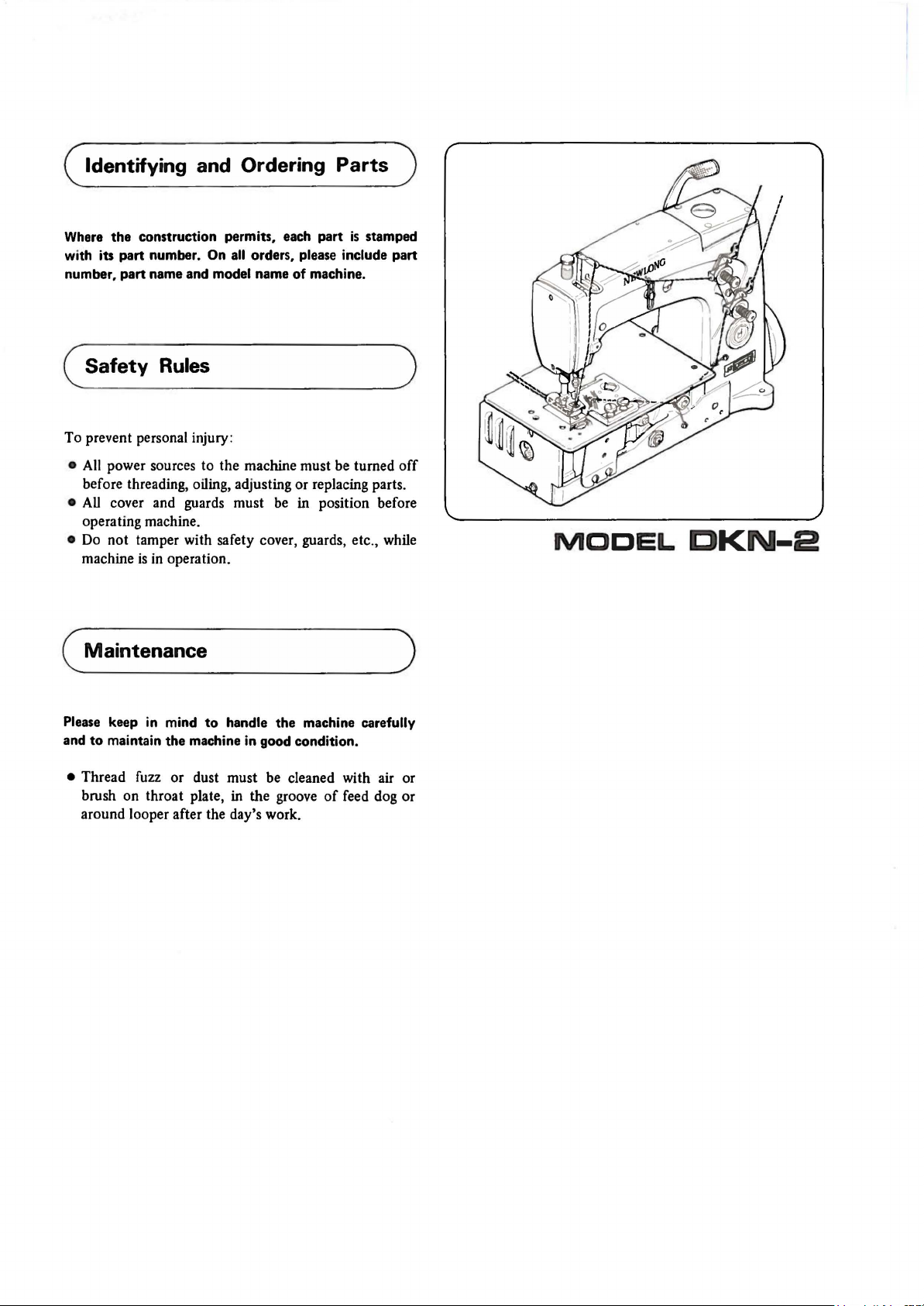
( Identifying and Ordering Parts )
Where
(
To prevent personal injury:
the
construction permits, each part
iu
with
number, part name and model name
•
•
•
part number. On
Safety
All
power sources to the machine must be turned
before threading, oiling, adjusting or replacing parts.
All
cover and guards must be in position before
operating machine.
Do
not tamper with safety cover, guards, etc., while
machine
Rules
is
in
operation.
all
orders, please include part
of
is
machine.
( Maintenance
stamped
)
off
)
MODEL
DKN-2
Please keep in mind
and
to
maintain
• Thread fuzz or dust must be cleaned with air or
brush on throat plate,
around looper after the day's work.
to
handle the machine carefully
the
machine in good condition.
in
the groove
of
feed dog or
MODEL
DKN-2
BAG
SEWING MACHINE HEAD
CONTENTS
SPECIFICATIONS
1.
THREADING (FIGURE 1)
2.
LUBRICATIONS . . . . . . . . . . . . . . . . . . . . . . . . . . . . . . . . . . . . . . . . . . . . . . . . . . . . . . . . . . . . 3
3.
ON SAFETY . . . . . . . . . . . . . . . . . . . . . . . . . . . . . . . . . . . . . . . . . . . . . . . . . . . . . . . . . . . . . . . 4
4.
ADJUSTMENT . . . . . . . . . . . . . . . . . . . . . . . . . . . . . . . . . . . . . . . . . . . . . . . . . . . . . . . . . . . . . 4
4
-1
Looper . . . . . . . . . . . . . . . . . . . . . . . . . . . . . . . . . . . . . . . . . . . . . . . . . . . . . . . . . . . . . . 4
4-2
4-3
4-4
4-5
4-6
4-7
Needle Mounting
Feed
Change
Needle Guard (Figure
Thread
Thread Tension .
............................................................
............
and
Height Adjustment .
Dog
........
of
Stitch Length (Figure refers) ...
Release
.
......
14
refers)
(Figure 15 refers) . . . . . . . . . . . . . . . . . . . . . . . . . . . . . . . . . . . . . . . . . . . . 7
...
.....
..............
. . .
....................
...
..
........................
.....................................
......
..
....................
..
.........................
..
.......
..
.....
..
............
. . .
...............
.
................
....
...
..
.
.......
........
2
.
...
2
5
. 6
7
7
7
4-8
4-9
4-10
5.
TROUBLESHOOTING . . . . . . . . . . . . . . . . . . . . . . . . . . . . . . . . . . . . . . . . . . . . . . . . . . . . . . . . 8
6. TIGHTENING OF
Presser
Presser
Needle Thread Tension and Guide (Figure 16 refers)
Bar Height (Figure 9 refers)
Foot
Pressure
SCREWS
(Figure 9 refers) ....
AND
NUTS . . . . . . . . . . . . . . . . . . . . . . . . . . . . . . . . . . . . . . . . . . . 8
.............
.....................................
- 1 -
..
...........
................................
..
...............
7
7
8
SPECIFICATIONS
Maximum speed:
Stitch range:
Seam:
Lubrication system:
Application:
Maximum thickness
Needle:
Thread:
1.
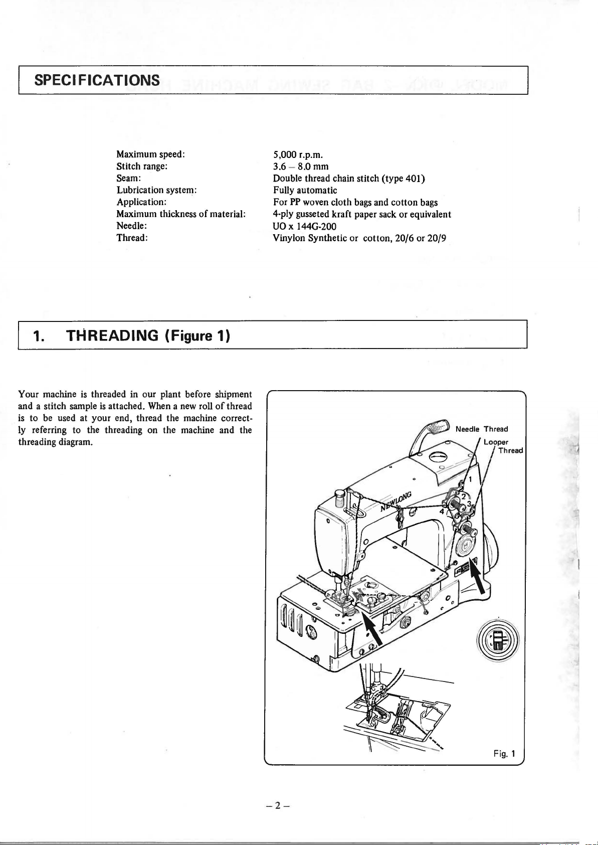
Your machine
and a stitch sample
is to be used at your end, thread the machine correctly referring to the threading on the machine and the
threading diagram.
THREADING (Figure 1)
is
threaded in our plant before shipment
is
attached. When a new roll
of
material:
of
thread
5,000 r.p.m.
3.6 - 8.0
Double thread chain stitch (type 401}
Fully automatic
For
4-ply gusseted kraft paper sack or equivalent
UO
Vinylon Synthetic or cotton, 20/6 or 20/9
mm
PP
woven cloth bags and cotton bags
x 144G-200
- 2 -
2. Lubrication
Oil
is
completely drained from the machine
before shipment. Never
before starting the machine. The proper procedure
follows (Figure 2 refers):
fail
to
fill
oil
in
our plant
in
the oil reservoir
is
as
~A
I
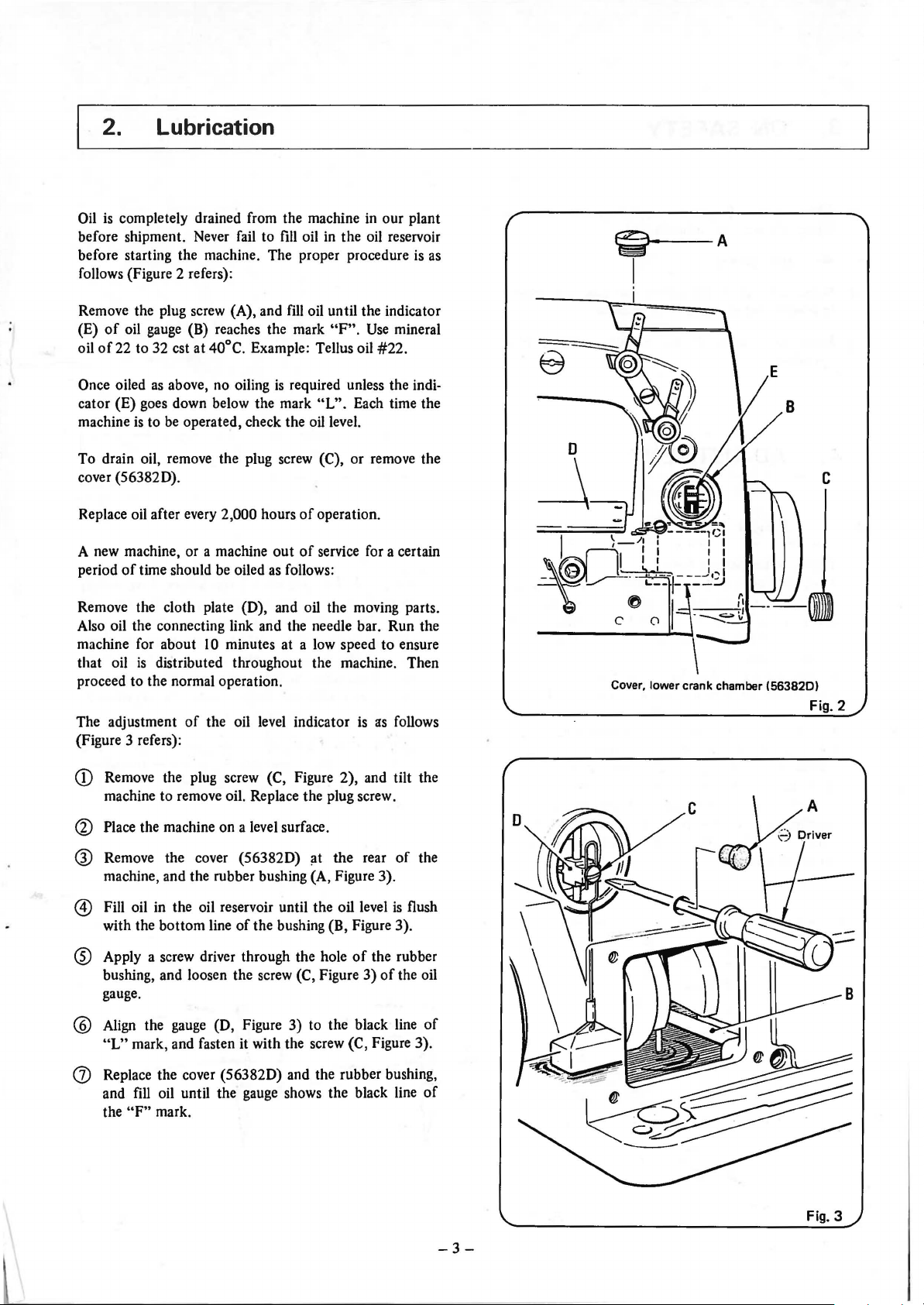
Remove the plug screw (A), and
(E)
of
oil
gauge
(B) reaches the mark
oil
of
22 to 32 est at 40°C. Example: Tellus oil
Once oiled
cator (E) goes down below the mark
machine
To drain oil, remove the plug screw
cover (563820).
Replace oil after every
A new machine, or a machine
period
Remove the cloth plate (D), and oil the moving parts.
Also oil the connecting link and the needle bar. Run the
machine for about
that oil
proceed to the normal operation.
The adjustment
(Figure 3 refers):
as
above, no oiling
is
to
be
operated, check the oil level.
2,000 hours
of
time should
is
distributed throughout the machine. Then
be
oiled
10
minutes at a low speed to ensure
of
the oil level indicator
fill
oil until the indicator
"F".
Use
#22.
is
required unless the indi-
"L".
Each time the
(C), or remove the
of
operation.
out
of
service for a certain
as
follows:
is
as
mineral
follows
Cover, lower crank chamber
(563820)
Fig. 2
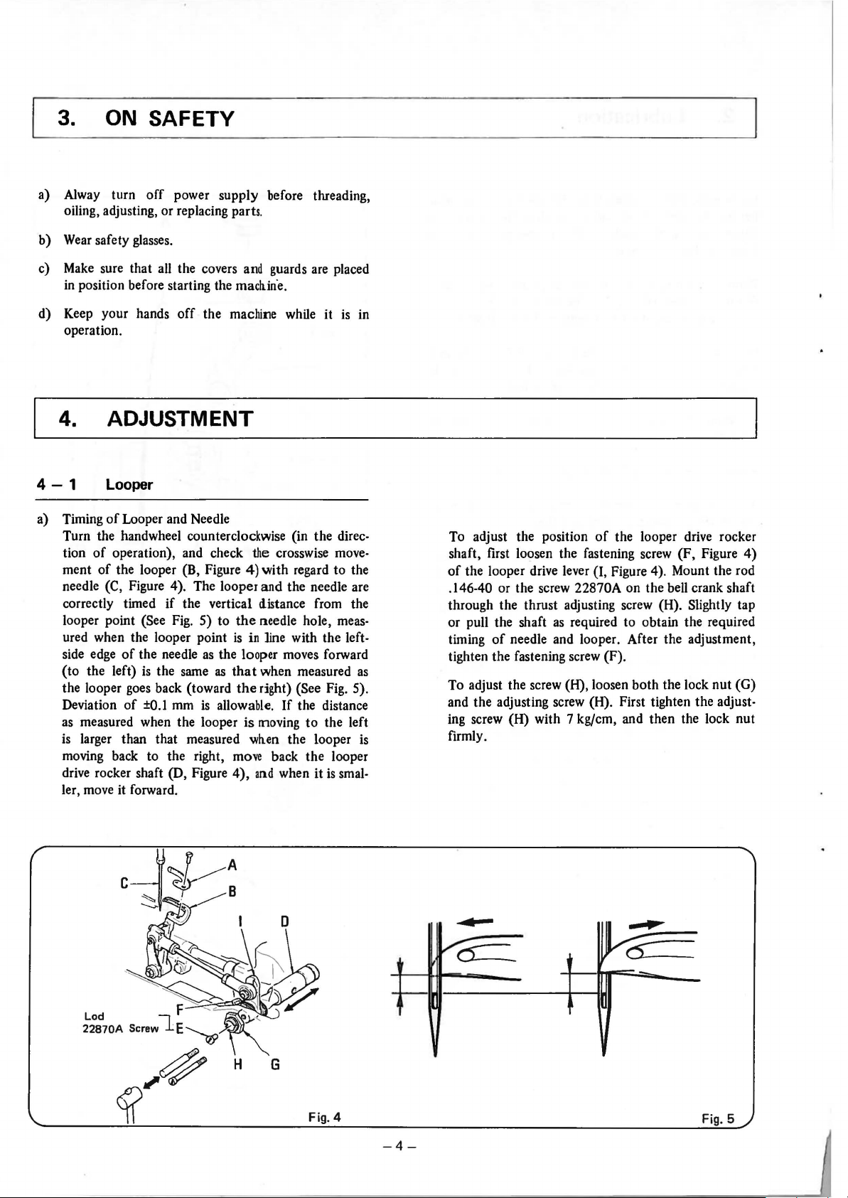
Q)
Remove the plug screw (C, Figure 2), and tilt the
machine to remove oil. Replace the plug screw.
Q)
Place the machine on a level surface.
® Remove the cover
machine, and the rubber bushing (A, Figure 3).
(563820)
11t
the rear
@ Fill oil in the oil reservoir until the oil level
with the bottom line
® Apply a screw driver through the hole
bushing, and loosen the screw
gauge.
@
Align
the
gauge
"L"
mark, and fasten it with the screw (C, Figure 3).
(J)
Replace the cover
and fill oil until the gauge shows the black line
the
"F"
mark.
of
the bushing
(D, Figure 3) to the black line
(563820)
(8,
Figure 3).
of
the rubber
(C, Figure 3)
and the rubber bushing,
is
of
of
the
flush
the oil
of
of
Fig. 3
-3-
3.
ON
SAFETY
a) Alway turn
oiling, adjusting, or replacing parts.
b)
Wear
safety glasses.
Make
c)
d) Keep your hands
sure that all the covers
in
position before starting the
operation.
4.
4-1
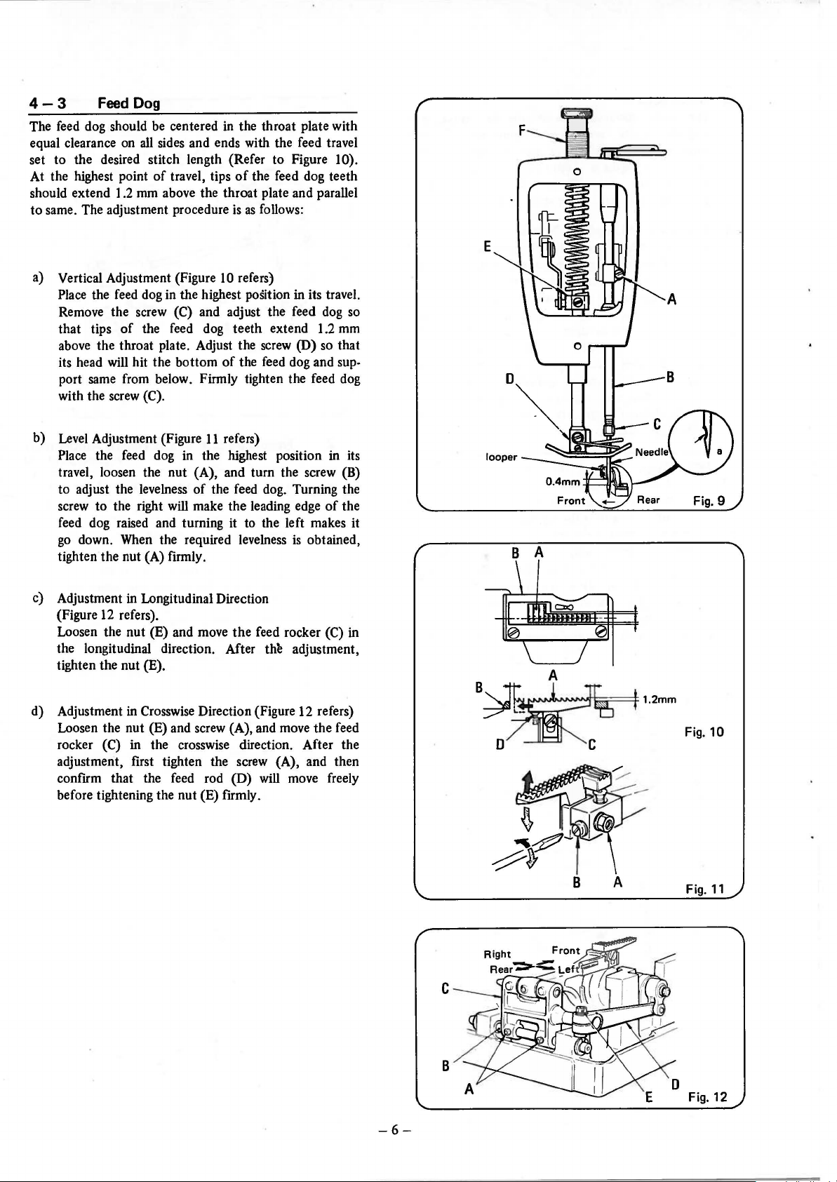
a) Timing
Turn the handwheel counterclockwise (in the direction
of
ment
of
needle (C, Figure 4). The looper
correctly timed
looper point (See Fig. 5)
ured when the looper point
side edge
(to
the left)
the looper goes back (toward
Deviation
as
measured when the looper
is
larger than that measured
moving back
drive rocker shaft (D, Figure
ler, move it forward.
off
power supply before threading,
and
mach.in·e.
off
the machine while
ADJUSTMENT
Looper
of
Looper and Needle
operation), and check
the looper
of
the needle
of
(B,
Figure 4)
if
the vertical distance from the
to
the
is
as
the looper moves forward
is
the same
±0.1
to
the right,
mm
as
that
is
allowable.
move
4),
the
is
guards are placed
the
crosswise move-
with
regard
and
the needle are
needle hole, meas-
in line with the left-
when measured
right) (See Fig. 5).
If
the distance
moving
wh.en
the looper
back the looper
and
when
to
it
it
is
in
to
the
as
the left
is
smal-
To adjust the position
shaft, first loosen the fastening screw
of
the looper drive lever (I, Figure 4) . Mount the rod
.146-40 or the screw 22870A on the bell crank shaft
through the thrust adjusting screw (H). Slightly tap
or pull the shaft
timing
tighten the fastening screw (F).
To adjust the screw (H), loosen
and the adjusting screw (H). First tighten the adjusting screw (H) with 7 kgjcm, and then the lock nut
is
firmly.
of
needle and looper. After the adjustment,
of
the looper drive rocker
(F,
Figure
as
required to obtain the required
both
the lock
nut
4)
(G)
-4-
Fig. 5

b) Looper Stroke
The center distance between the bell crank stud
and the looper carrier shaft should be
when the looper
as
shown
in
loosening the screw (B)
the adjustment, tighten the screw (B).
c) Adjustment
The distance between the looper point and the needle
center should
farthest right position,
sary adjustments are carried
Place a new needle
in
the needle bar as deep as it will go. Tighten the
needle with the needle bar nut. Turn the pulley
until the looper reaches its extreme right-hand posi-
tion. Loosen the nuts (A) and (B), and turn the joint
rod (C) until the required distance
Having adjusted, tighten the nuts
holding the joint rod (C).
Note: Make sure that the front face
joint,
not in contact with the oil receiver (E)
other pats after the adjustment.
In the next place, adjust the looper so that the
looper point will lightly touch the needle as it passes
behind the needle. However,
the needle. For this adjustment, loosen the screw
and turn the stop screw (G)
to the right will make the looper
and turning it to the left will make the iooper get
nearer to you.
After the adjustment, tighten the screw
check the movement
Figure 8-a).
d) Mounting
Mount the loop guide so that
the front side
forward (Refer to Figure 8-b).
of
is
in the farthest right position,
Figure 6. Adjustment can be made after
of
the bell crank. After
of
Looper and Needle
be
4 mm when the looper
as
shown in Figure 7. Neces-
out
as
follows:
of
the specified type and size
is
(A)
and (B) while
of
left, (D)
Loop Guide
of
is
correctly vertical, and
it
should never push
as
required. Turning it
go
away from you,
of
the looper again (Refer to
it
will lightly contact
the needle as the looper moves
I 03.2 mm
is
at the
obtained.
the ball
or
(F)
(F),
and
Looper
Looper Drive Lever
Stud
(looper
rocker cone)
Fig. 6
4-2
is
A needle
in
the needle bar as deep as it will go. The shaved part
the needle should face away from you. Tighten
bar
Adjust the height
point
reaches the left edge
To
after loosening the screw (A)
When the proper height
of
screw (A).
Note:
Needle Mounting and Height Adjustment
(Figure 9 refers)
of
the specified type and size should be inserted
the
needle
nut
(C) firmly so that needle will
of
the needle bar
is
0.4 mm above the needle hole when
of
the needle,
adjust, move the needle bar in the vertical direction
is
obtained , check
the shaved part
If
_the
the looper will strike against the needle and may
break it. Further, thread break or damage to
thread may also result.
of
direction
the needle again, and tighten the
of
the needle
not
come off.
so
that the looper
the
as
shown in Figure
of
the needle bar holder.
the
position
is
not
correct,
looper
of
5.
Loope
Guide
(a)
0
E
(b)
Fig. 7
-5-
Needle-~~~~==:\
f
\~+
~
Loope Guide
Fig. 8
Feed
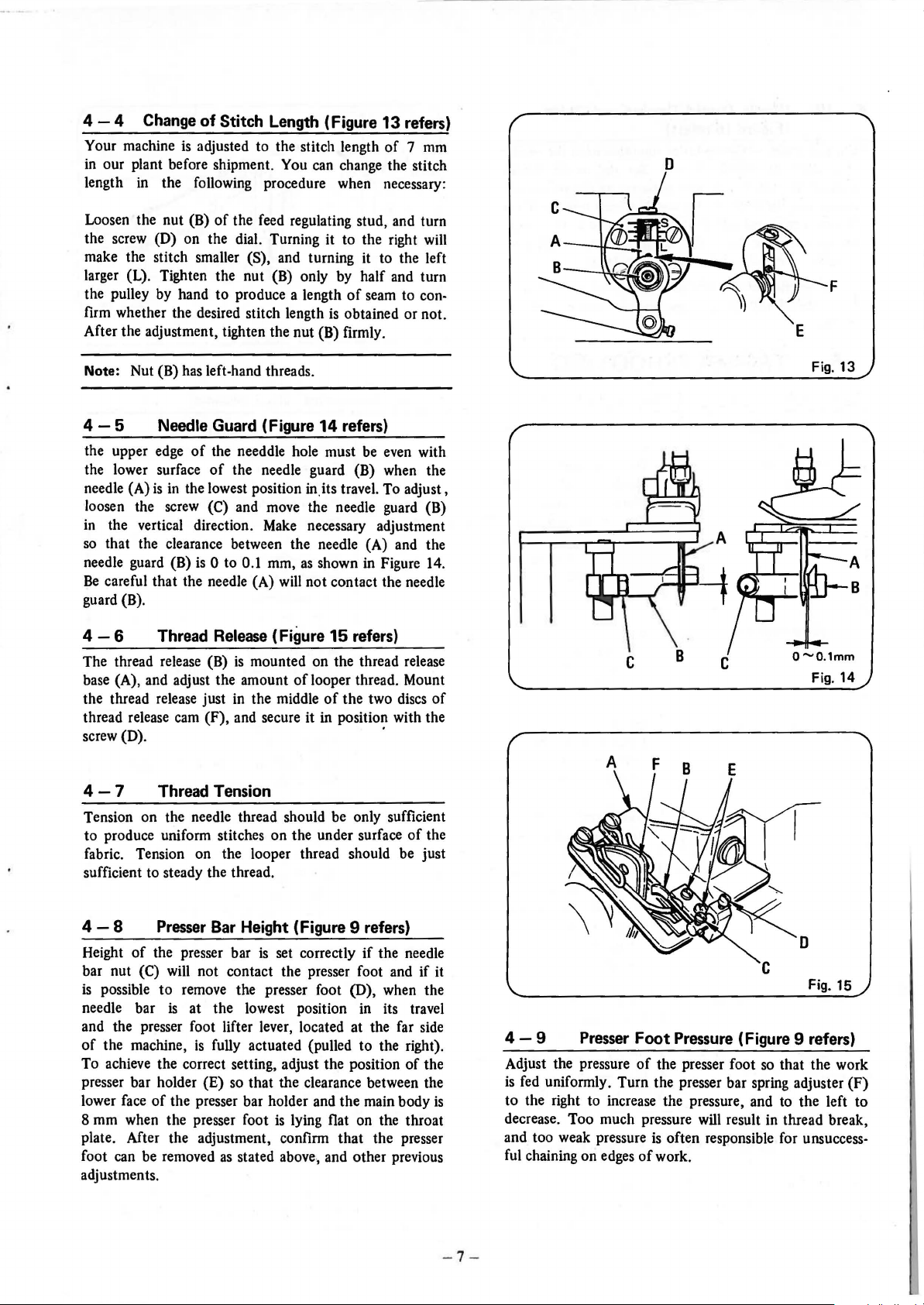
4-3
The
feed
dog should
equal clearance
set to the desired stitch length (Refer to Figure
At the highest point
should extend 1.2
to same. The adjustment procedure
Dog
be
centered
on
all
sides and ends with the feed travel
of
travel, tips
mm
above the throat plate and parallel
in
the throat plate with
of
the feed dog teeth
is
as
follows:
10).
0
a) Vertical Adjustment (Figure
Place the feed dog in the highest position in its travel.
Remove the screw
that tips
above the throat plate. Adjust the
its head will hit the bottom
port
with the
b)
Level
Place the feed dog in the highest position in its
travel, loosen the nut (A), and
to adjust the levelness
screw to the right will make the leading edge
feed dog raised and turning it to the left makes it
go
tighten the nut (A) firmly.
c) Adjustment in Longitudinal Direction
(Figure
Loosen the nut (E) and move the feed rocker
the longitudinal direction. After
tighten the nut
of
same
from below. Firmly tighten the feed dog
screw
Adjustment (Figure
down.
12
When
refers).
(C) and adjust the feed
the feed dog teeth extend 1.2
(C).
the required levelness
(E).
10
refers)
screw
(D)
of
the feed dog and sup-
11
refers)
tum
the screw
of
the feed dog. Turning the
is
thll adjustment,
dog
so
mm
so
that
(B)
of
the
obtained,
(C) in
B A
d) Adjustment in Crosswise Direction (Figure 12 refers)
Loosen the nut (E) and screw (A), and move the feed
rocker
adjustment, first tighten the screw (A), and then
confrrm that the
before tightening the nut (E) firmly.
(C) in the crosswise direction. After the
feed
rod (D)
will
move freely
c
B
B
A
Fig.
10
Fig.
11
Fig. 12
-6-
4-4
Your machine is adjusted to the stitch length
in
length
Change
our plant before shipment. You can change the stitch
in
of
Stitch Length (Figure 13 refers)
of 7 mm
the following procedure when necessary:
D
Loosen the nut (B)
the screw (D) on the dial. Turning
make the stitch smaller
larger (L). Tighten the nut (B) only by half and turn
the pulley by hand to produce a length
firm whether the desired stitch length is obtained or not.
After the adjustment, tighten the nut (B) firmly.
Note: Nut (B) has left-hand threads.
4-5
the upper edge
the lower surface
needle (A)
loosen the screw
in
the vertical direction.
so
that the clearance between the needle (A) and the
needle guard (B)
Be
careful that the needle (A) will not contact the needle
guard (B).
4-6
The thread release (B)
base (A), and adjust the amount
the thread release just in the middle
thread release cam (F), and secure it in position with the
screw (D).
Needle Guard (Figure 14 refers)
is
Thread
of
the feed regulating stud, and turn
it
to the right will
(S), and turning it to the left
of
seam to con-
of
the needdle hole must be even with
of
the needle guard
in
the lowest position in. its travel. To adjust,
(C) and move the needle guard (B)
Make
is
0 to 0.1 mm,
Release
is
mounted on the thread release
as
(Figure
of
{B)
when the
necessary adjustment
shown in Figure 14.
15
refers)
looper thread. Mount
of
the two discs
·
of
Fig.
Fig.
F
13
14
4-7
Tension on the needle thread should be only sufficient
to produce uniform stitches on the under surface
fabric. Tension on the looper thread should be just
sufficient to steady the thread.
4-8
Height
bar nut
is
possible
needle bar
and the presser foot lifter lever, located at the far side
of
the machine,
To achieve the correct setting, adjust the position
presser bar holder {E) so that the clearance between the
lower face
8 mm when the presser foot
plate. After the adjustment, confirm
foot can be removed
adjustments.
Thread Tension
Presser
of
the presser bar
(C) will not contact the presser foot and
to
of
Bar Height (Figure 9 refers}
is
set correctly
remove the presser foot (D), when the
is at the lowest position in its travel
is
fully actuated (pulled to the right).
the presser bar holder and the main body
is
lying flat on the throat
as
stated above., and other previous
if
that
the needle
the presser
of
of
the
if
the
A F
D
it
4-9
Adjust the pressure
is
fed uniformly. Turn the presser bar spring adjuster
is
to the right to increase the pressure, and to the left to
decrease. Too much pressure will result in thread break,
and too weak pressure
ful chaining on edges
Presser
Foot
Pressure
of
the presser foot
is
often responsible for unsuccess-
of
work.
(Figure 9 refers)
so
Fig.
15
that the work
(F)
- 7-
 Loading...