

NEWLONG
MATPARTS
MODEL
NEWLONG
MACHINE
WORKS,
LTD.
(
MATPARTS
Identifying and
Where the constru~tion~permits, each part is stamped
with its
number, part name
part
number.
Ordering
On all
and
model name
Parts
orders, please include part
of
machine.
)
[
+f
-
E
x
LZ
88
if
5
bj
Fu~
&
*
)
(Safety
To prevent perdonal injury:
All power sources to the machine must be turned
threading, oiling, ajusting or replacing
All cover and guards must
machine.
Do not
is in operation.
Maintenance
Please keep in mind to handle the machine carefully
and
to msintenance the in good condition.
Thread fuzz or dust must be cleaned with air or brush after
the day's work.
tamper
Rules
parrs.
be
in position before operating
with
safety cover, guards, ctc., while machine
off
1
before
(H
s
~~~R%~~EE&IJ\S&%F~~~~X%~~~~TL\~T~
ZS;%
1
sa>{$%hf4$7~&
~~~~~d7~~~~~~~~~~~~~o
<
@
5
2
2
%
IZ%IZE{%IZI~!%\I~TT
Lf:(;.
%'k~f;13i.9.
2
Li0
Hi;
3.
MATPARTS
ADJUSTMENT
/
CONTENTS
...............................................
4
3-1) ADJUSTING THREAD TENSION
3-2)
SETTING NEEDLE AND ADJUSTING NEEDLE BAR HEIGHT
&tDiT!743I3ZBU$t&D&
3-3) TIMING SHUTTLE RACE BODY AND NEEDLE
@*EA+St
3-4) ADJUSTING PRESSER FOOT HEIGHT AND TIMING WITH NEEDLE
@~&a~st$t&aa%
3-5) ADJUSTING PRESSER FOOT PRESSURE
4.
REPLACING BOBBIN THREAD
5.
OPERATION
/
82
Dl%
................................................
2
/
@
-*-.--*
*
***
@I&EEcr)i@B
. .
-
.***-.-
....--.-m.""
**-**-u-""'
-uu"*
-**-".-
**
**
.
4
4
4
5
5
*
6
-7
PARTS LIST
/
...............................
.............
9
1.
MATPARTS
SPECIFICATIONS
Maximum speed:
Stitch width:
type:
Stitch
Needle:
Thread:
2.
THREADING
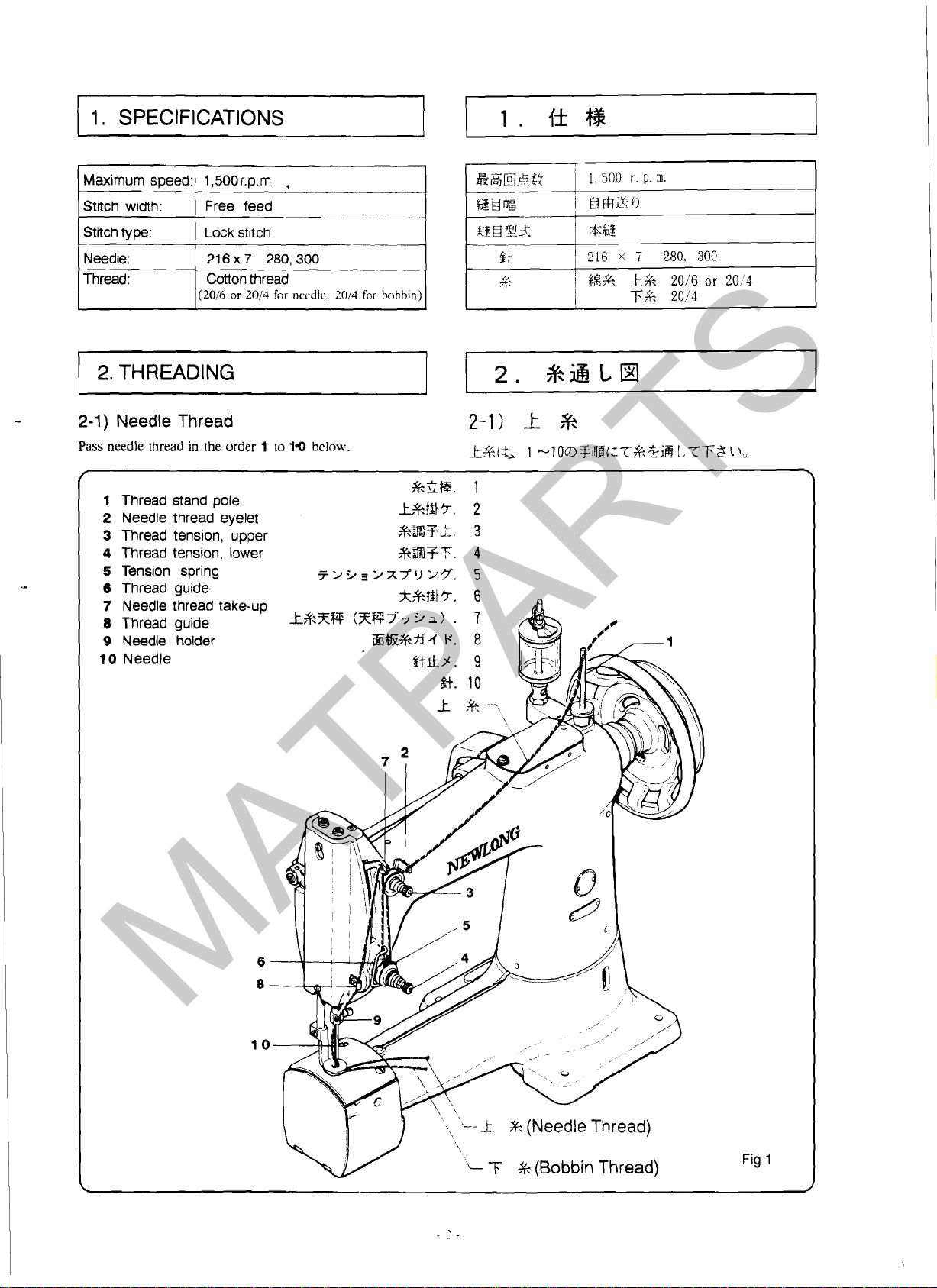
2-1)
Needle
Pass needle thread
1
Thread stand pole
2
Needle thread eyelet
3
Thread tension, upper
I
Thread tension, lower
Tension spring
Thread guide
Needle thread take-up
Thread guide
Needle holder
Needle
1,500
Free feed
Lock stitch
216x
Cotton thread
(2016
Thread
in
the order 1 to
r.p.m.
7
or
2014
,
280,300
for
necdle;
1.0
1%
---
-
-
-
2014
for
hohhin)
below.
A+337T.
7.
(3'
>
4
?
4
5
.
7
.
8
.
Fig
'"
7;
&
(Bobbin
Thread)
1
1
2-2)
MATPARTS
Bobbin
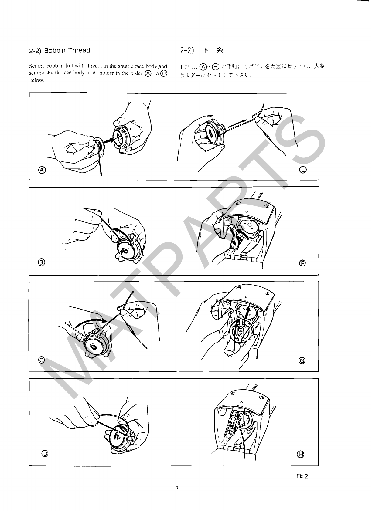
Thread
2-21
-F
3+
Set the bobbin, full
set the shuttle race
below.
with
body
thread.
in the shurtlc race body,and
in
holder in the
order @ to
(@
F%(t,
,;
g-
@--@
(=+.
,;
~-~illWi~?$
L
77;
t"i&fi;%CZ+z
g
,c
.Y
b
L.
Fig
2
3
-
3.
MATPARTS
ADJUSTMENT
3-1)
Adjusting
Check a sample seam to see the tightness
tight needle thread, loosen thread tension, upper
Tighten
adjust, turn thread tension nut.
3-2)
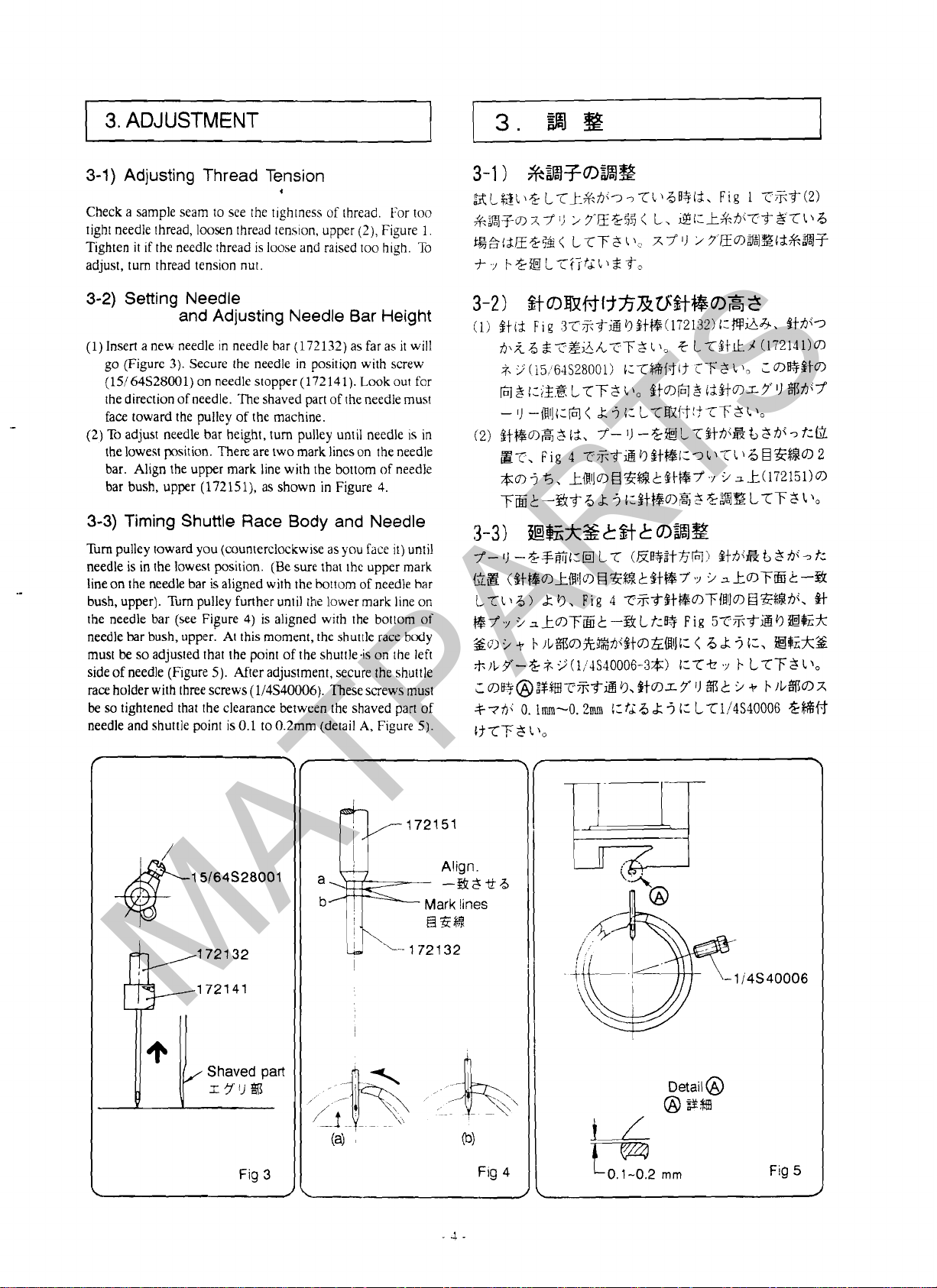
(1) Insert a new needle in needle bar (172132) as far as
-
(2) To adjust needle bar height, turn pulley until needle
3-3)
Turn pulley toward you (counterclockwise as you face
needle is in the lowest position.
line on the needle bar is aligned with the bottom of needle
bush, upper). Turn pulley further until the lower mark line on
the needle bar (see Figure
needle bar bush,
must
side of needle (Figure
race holder with three screws
be
needle and shuttle point
it
-
if the needle thread is loose and raised too high. To
Setting
go (Figure
(15164S28001) on needle stopper (172141). Look out tbr
the direction of needle. The shaved part
face toward the pulley of the machine.
the lowest
bar.
Al~gn the upper mark line with the bottom
bar bush, upper
Timing
be
so adjusted that the point of the shuttleis
so tightened that the clearance between the shaved part of
Thread Tension
e
of
thread. For too
(I),
Figure
-
Needle
and
Adjusting Needle Bar Height
3).
Secure the needle in position with screw
of
the needle must
position.
There are two mark lines on the needle
of
(172151), as shown in Figure
Shuttle
upper: At this moment, the shut~le race body
Race
5).
After adjustment, secure the shuttle
is
0.1 to 0.2mm (detail
Body and
(Be
sure that the upper mark
4)
is aligned with the bottom of
(114S40006). These screws must
4.
Needle
on
the left
A,
Figure
it)
1
it
will
1s
in
needle
until
bar
5).
3-1)
~it$~i~+~14_%h~~~11~6031d.
&flF~xy
&gr$Eg<&
t-.Y
3-21
(1) $+id
(2, $Jr~Dis,$
3-3)
7-
G,23
L?l)b)
+$$Y
Sol
;t;)LY-?&;i. 9 (li:+IS40006-3$)
c
%77Y
if7-F$
832lFU3aZ
1;
)
Y'J3555
{
L?7;$
i.fC-@L?ii~il)zE$,
l
<
L,
$i:k%h<T$$Tl\6
xll)
i
$tDRXktV3BCJ%t#~S2
Fig
3?;T;$;g
7S\L6
~~E;SA.TT'~
;i.
9
(i5:6+1~28001)
m3i:iB3
-
I)
a?.,
*D5!5,
L-crTS
-iRlli~6l<
It,
Fig
4
~~~~~~~%lc?$t~7~~ >xk(l72151)D
TEk--%f
4
Qtg(172132)
l)"
C
L7Stk.A
c:-crHc$if
L)o
k
3
4:
L7%!t4'!57T3
7'-
'9
--%BL?$tA<i%t
TZ$&t3$t@i:'l,l\?l~BRZ$$~2
6
h
3
c:PtWIS3%3E
rT'$
$tom$
i2HDI-7'lJ
~&~S&$+kIn%@
1)
-~+K~:IEI
($tt&OlkiFlilc?l €IZfSk$t%7'~.:,
dr
.i,_tDT&t:-!&LL:Q
.i
-P
+
1L%a%2%hX$ta&UltJi:
~B-+@;$~IT%-oB
0. lrrun-O.2mm
l\o
13,
LT
(EB+Zt36!)
Fig
4
~,?;t$t@o>T;lflll~HEK:~hi,
Fig
<
t:T+
5.
$tar
7
11
%f3
!:ti
b
5
C:
LT114S40006
Fig 1
T%$(2)
TBOE%l2kk&~~
l~#&?+.
i
$thX~
(172141)a
)7
L
o@Sta
%7YY'
l)o
3ni
-3
?:KL
LTT:!
gti~q~h
.i
x_tOlf;%t:-%
1~
si~q-t:
@f
57
iifiTiBfiC1Ek
6
.k
3
i:,
?@%A%
.r
i-
LTTf
L
.i
1),
+
111/%c~x
%$%$f
3-4)
MATPARTS
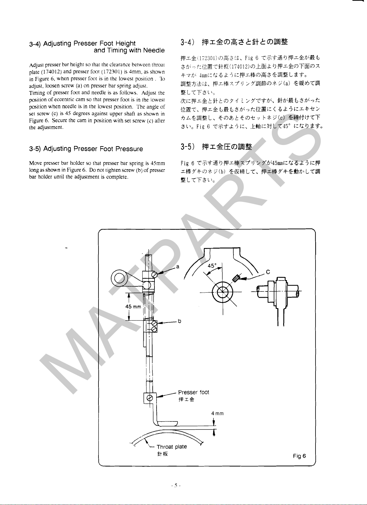
Adjusting Presser Foot Height
and Timing with Needle
Adjust presser bar height so that the clearance between throat
plate (174012) and presser foot (172301) is
in Figure
adjust, loosen screw (a) on presser bar spring adjust.
Timing of presser foot and needle is as follows. Adjust the
position of eccentric cam so that presser foot is in the lowest
position when needle
set
Figure
the adjustment.
3-5)
Move presser bar holder so that presser bar spring is 45mm
long as shown in Figure
bar holder until the adjustment is complete.
6,
when presser foot is in the lowest position . lo
is
in the lowest position. The angle of
screw (c) is 45 degrees against upper shaft as shown in
6.
Secure the cam in position with set screw (c) after
Adjusting Presser
Foot
6.
Do not tighten screw
4mm,
Pressure
(b)
as shown
of presser
/
\
Throat
\
NC
plate
Fig
6
1
 Loading...