

Page 1
New Eagle Consulting www.neweagle.net PH: 734.929.4557
C4MAX
v2
Installation
G
uide
Internal & external ante
nna
Version
1.2
4/18/2018
Page 2

New Eagle Consulting www.neweagle.net PH: 734.929.4557
Table of contents
Preface
..............................................................................................................3
Warnings
and notices
.........................................................................................3
1.
Hardware description ....................................................................................4
2.1. C4MAX v2
with external antenna
............................................................4
2.2. C4MAX v2
with internal
antenna............................................................5
2.3. Recomme
ndation for both
types
.............................................................6
2.
Preparing/installing
the device......................................................................7
2.1. Open the
device
to
insert a sim card
.......................................................7
2.2.
Connect
the GSM/GPS external antenna
................................................9
2.3. Choose
the appropriate
location for
mounting
........................................9
2.4.
Insert the device
on
harness
..................................................................10
2.5.
Pin
out &
Wires description ...................................................................12
2.6.
Plug the device
to
the external battery
...................................................13
3.
Inputs activation threshold ...........................................................................13
4. Outputs information....................................................................................13
5.
LEDs sequences
..........................................................................................14
6. Su
pport
......................................................................................................14
Page 3

New Eagle Consulting www.neweagle.net PH: 734.929.4557
Preface
The
information contained in
this installation guide is subject to changes
in order to improve the
reliability, design
or
features
without prior notice. New Eagle reserves the right to make
changes
in
the content without obligation to
notify any person
or organization of such
changes
or
improvements.
New Eagle can in no
event
be held liable for
technical
or editorial
errors
or
omissions
herein, nor for incidental, special
or
consequential damages from the
furnishing, performance
or
use
of
this installation
guide.
Warnings
and notices
The exclamation
point
within
an
equilateral triangle is intended
to alert the
user
to the
presence
of
important operating
and
maintenance (servicing) instructions
in the literature
accompanying the
product.
Please read
the
installation
guidelines,
as well as the safety and
operating
instructions before
operating your device. Follow
all
instructions
and
heed
all warnings
in the
installation
guide.
There is a risk
of
explosion
if the
battery is replaced by
a wrong
battery type. Please discard empty
battery according
to local regulations.
Page 4
New Eagle Consulting www.neweagle.net PH: 734.929.4557
1.
Hardware description
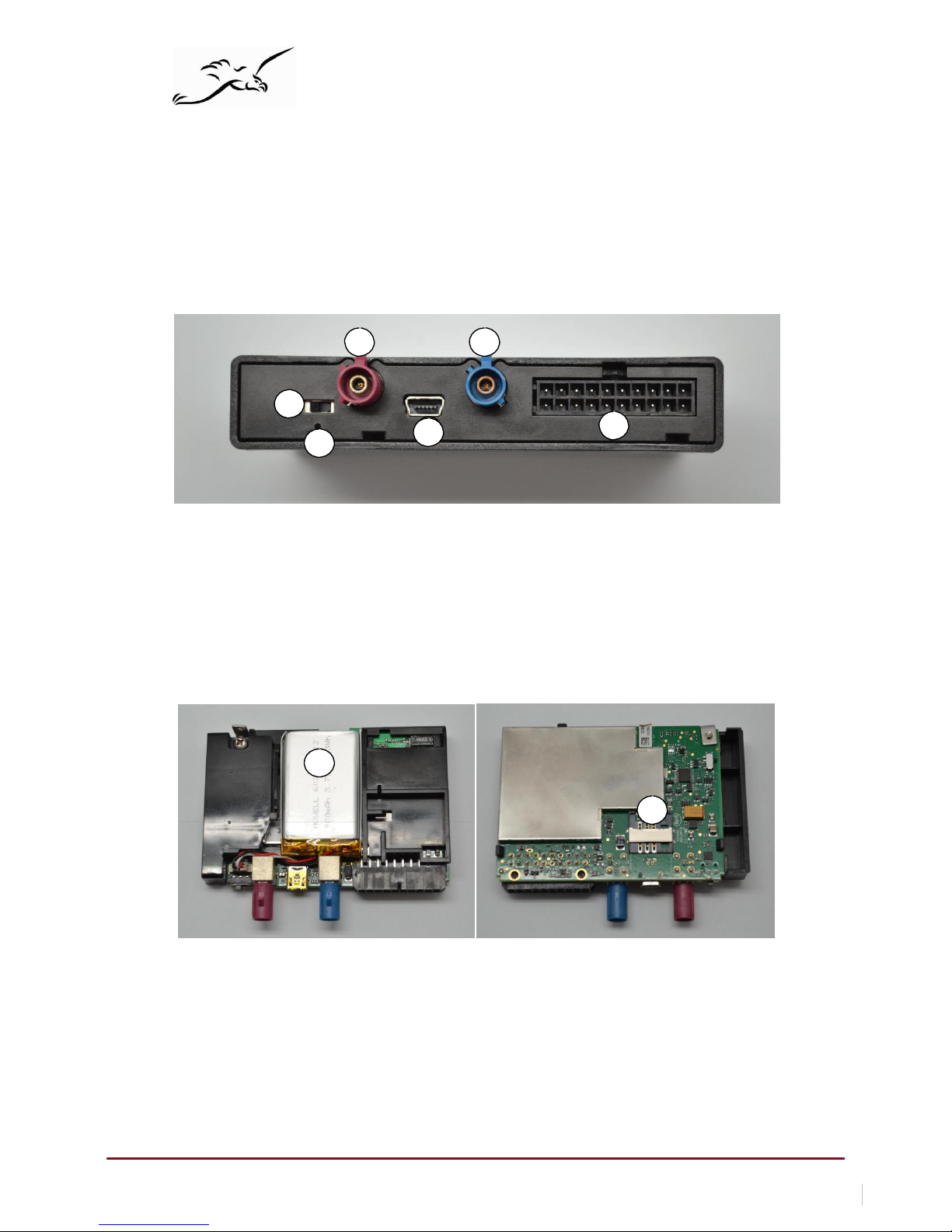
1.1. C4MAX
v2 with external ant
enna
Front:
1 2
5
3
4
6
1. GS
M connector
2.
GPS
connector
3.
USB
connector
4.
Molex (20pins)
connector
5.
Inner battery
switch
6.
LEDs
Inside:
1
2
1.
Internal battery
2.
SIM
card slot
Page 5
New Eagle Consulting www.neweagle.net PH: 734.929.4557
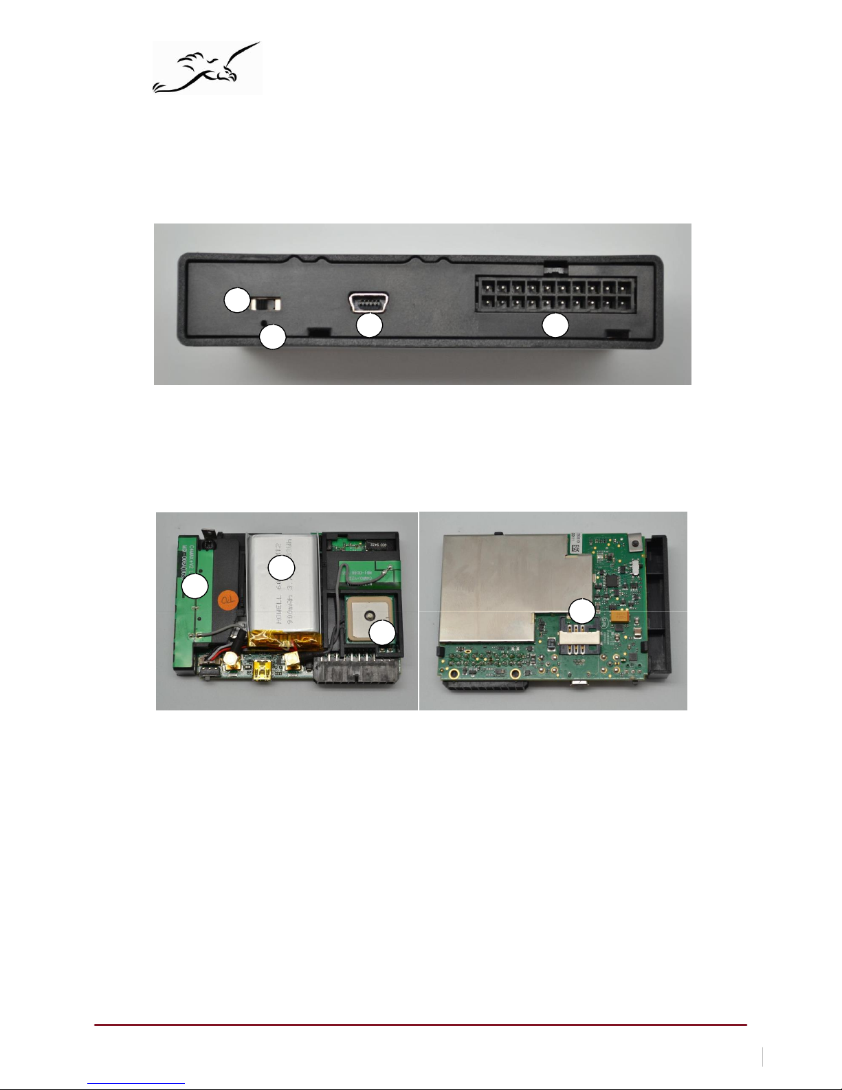
1.2. C4MAX
v2 with internal ant
enna
Front:
3
1 2
4
1.
USB
connector
2.
Molex (20pins)
connector
3.
Inner battery
switch
4. LEDs
Inside:
1
2
4
3
1.
Internal battery
2.
Internal GS
M antenna
3.
Internal GPS
antenna
4.
SIM
card slot
Page 6
New Eagle Consulting www.neweagle.net PH: 734.929.4557
1.3.
Recommendation for both types:
Move the switch inwards (I) to activate the internal battery.
The switching ON
of the internal
battery requires
a running
system. This is
about
10
seconds after
ignition
(the
led 4
must
be lit
then unlit).
Move the switch outwards (O)
to deactivate the internal battery.
The switching OFF
of the internal
battery is instant. Thus, do
n
’t switch
off the internal
battery
if the
device is running without
be
connected
to an
external battery.
If using a custom SIM, the SIM
card
PIN code must
be deactivated.
Page 7
New Eagle Consulting www.neweagle.net PH: 734.929.4557
2. Preparing/insta
lling the device
2.1.
Open
the device to insert a sim card
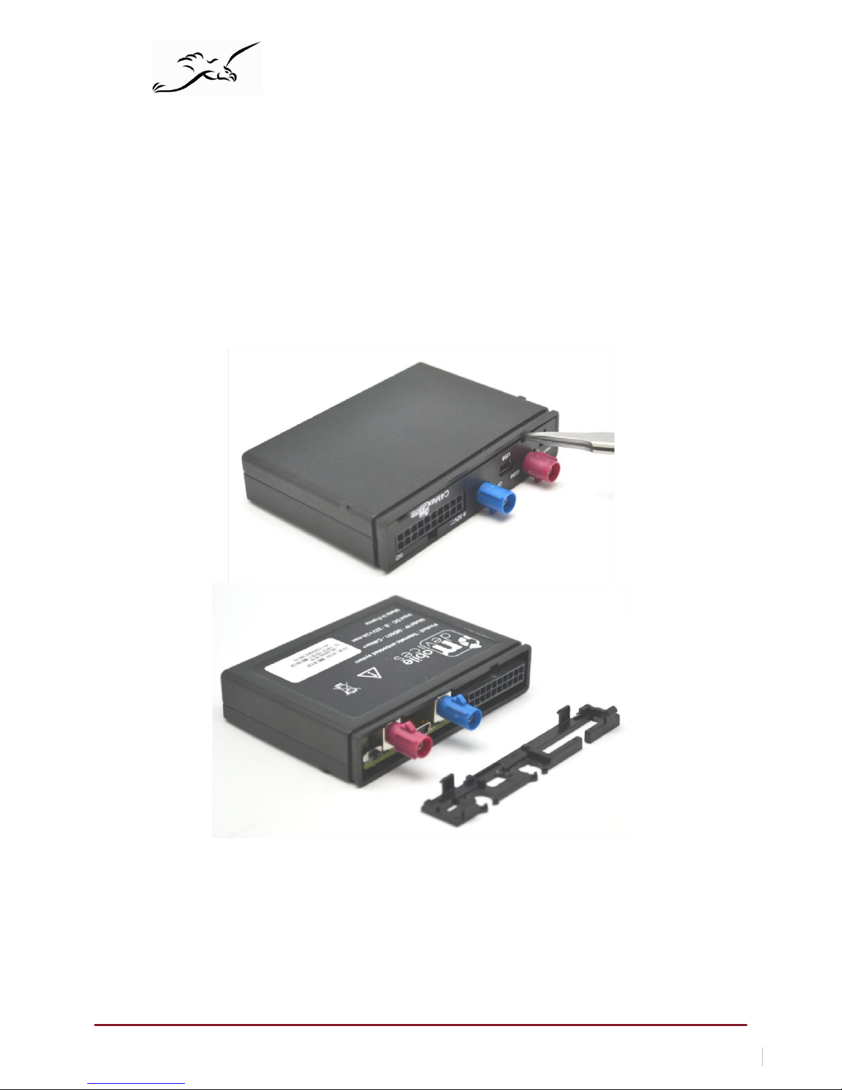
If you ordered your device without a SIM card (e.g. you are planning to use your own SIM card). Please follow
the directions below to install the SIM card.
Insert
a flat
screwdriver
into the 2
holes
and
pry
it to
remove
the back cover.
Be careful not to insert the screwdriver too far into the case, as you may contact the
circuit board inside and damage it.
Page 8
New Eagle Consulting www.neweagle.net PH: 734.929.4557
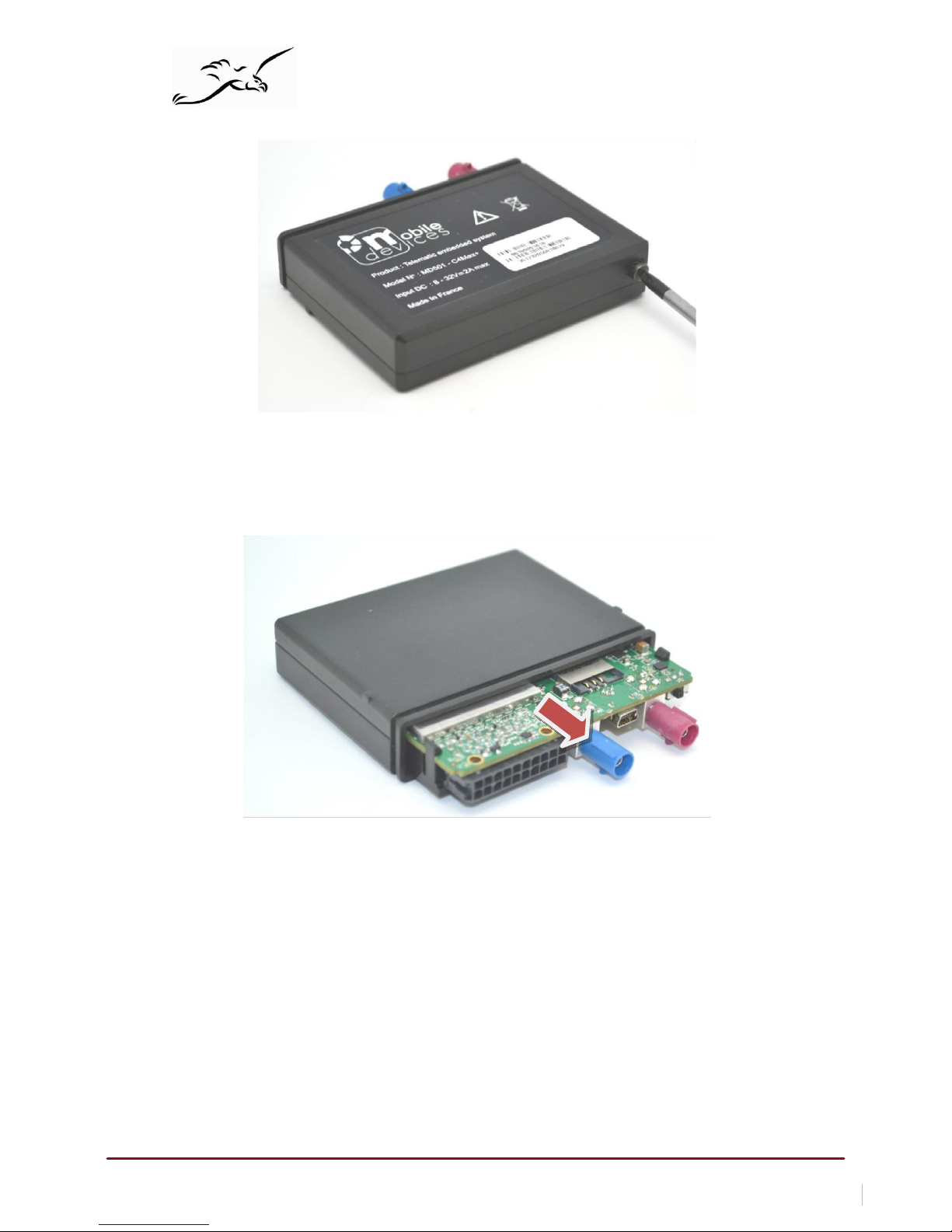
Unscrew
the
screw
at the back of the device
Afterwards
pull on the
PCB
to
release
it.
Page 9
New Eagle Consulting www.neweagle.net PH: 734.929.4557
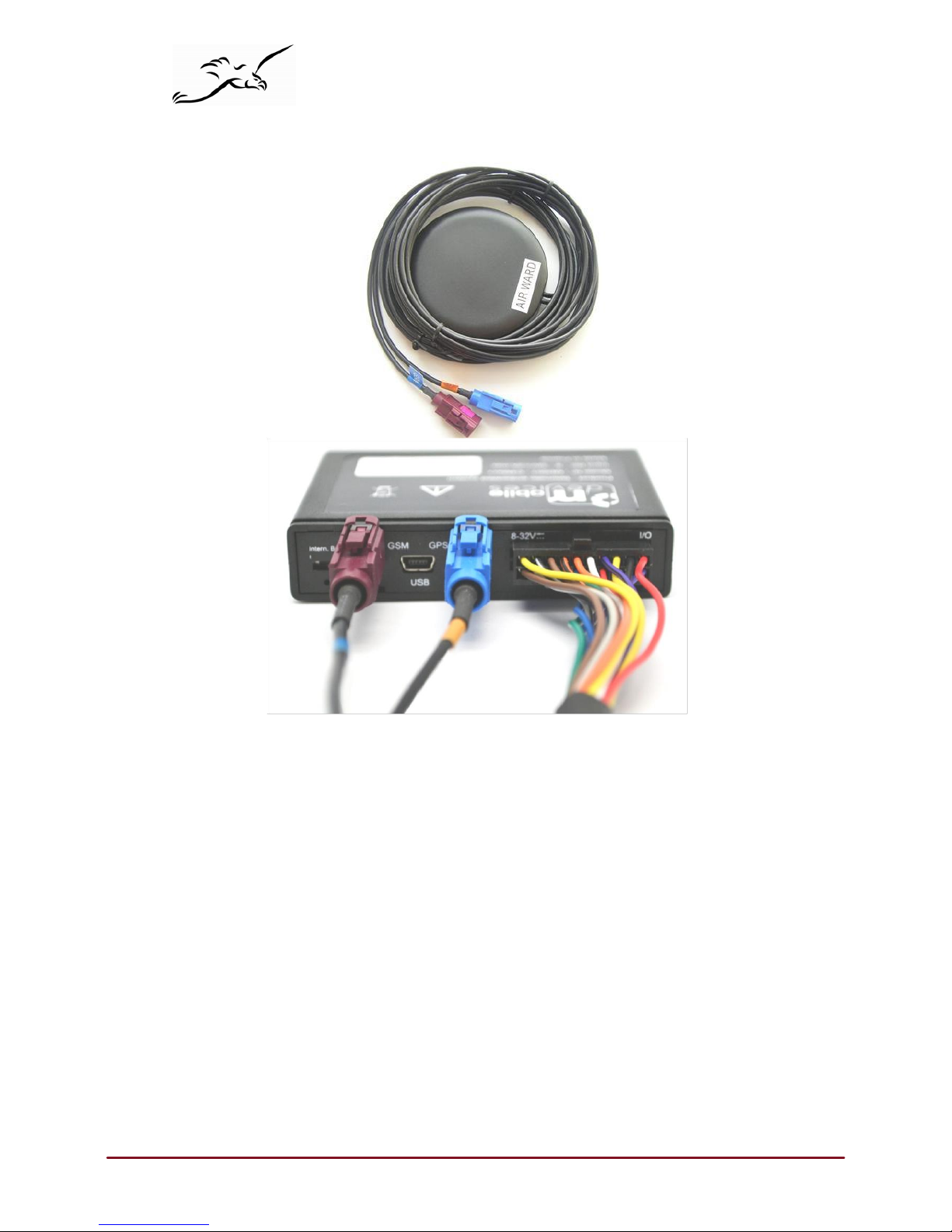
2.2.
Connect the GSM/GPS external
antenna
2.3. Choose
the appropriate location for mounting
The
ideal location for
mounting
the
device is under
the
dashboard. However, some types
of coated
windshields, as
well
as windshields with
an
in-screen heating system
can block
GPS signals. External
antenna should never be covered
by any
kind of object or material,
especially
not
by
metal or
aluminum. Transmission
and
reception
of
GPS signal is however
not
hindered by plastic
or normal
glass. Moreover,
put at
least
20 cm
between
the
antenna
and a speaker.
Page 10
New Eagle Consulting www.neweagle.net PH: 734.929.4557
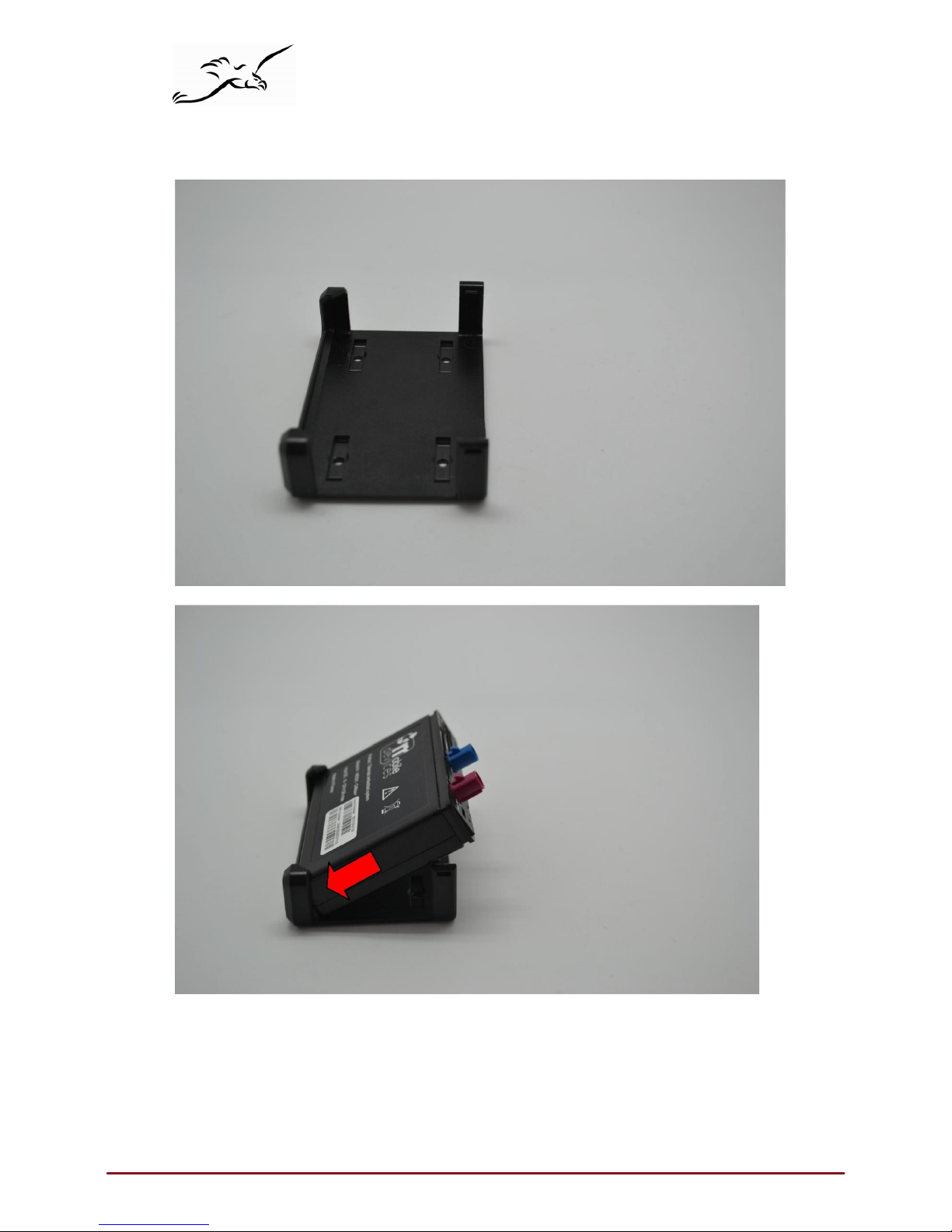
2.4.
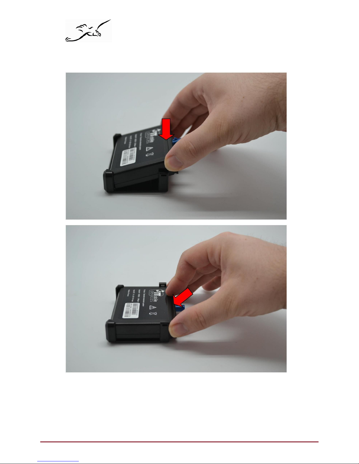
Insert the device on
harness
Page 11
New Eagle Consulting www.neweagle.net PH: 734.929.4557
Page 12
New Eagle Consulting www.neweagle.net PH: 734.929.4557
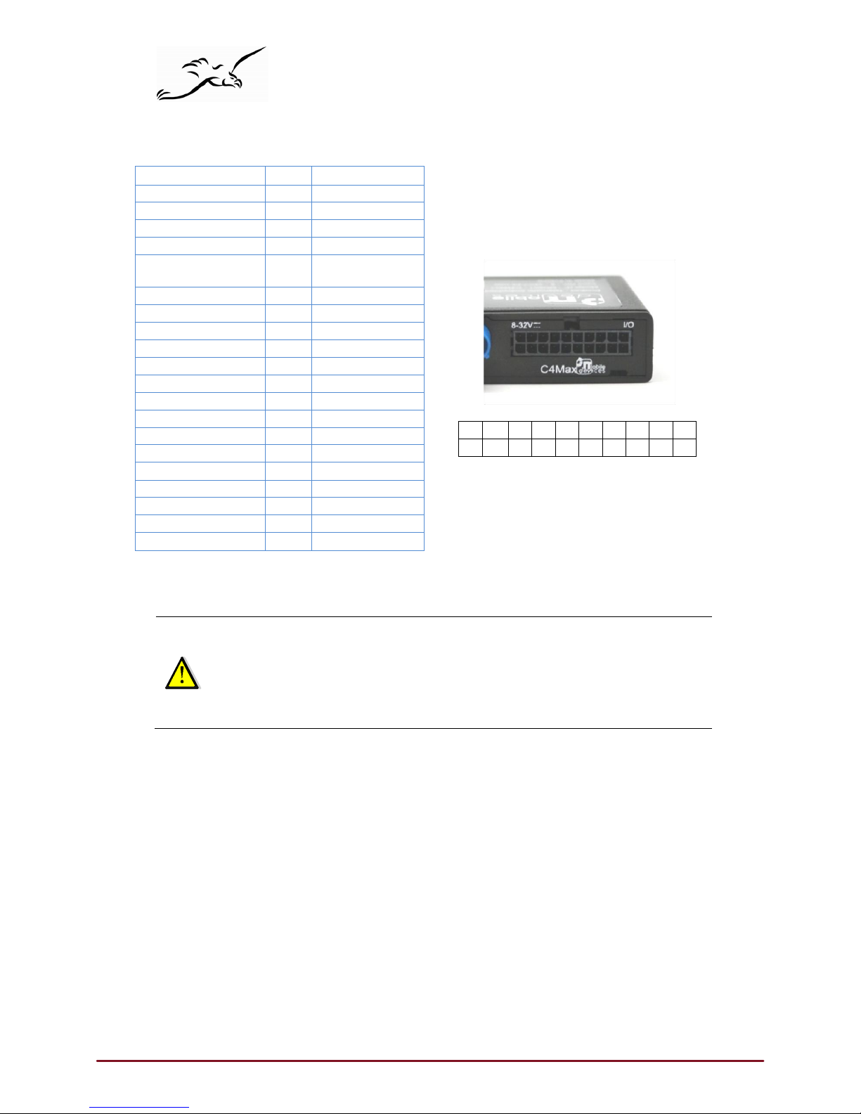
20 19 18 17 16 15 14 13 12 11
10 9 8 7 6 5 4 3 2 1
2.5.
Pin out & Wires description
Signal Pin
Color
DIG_OUT1
1
Purple
DIG_OUT2
2
Blue
RS
485_A
3
White with
black
RS
485_B
4
Red with
black
DIG_IN1
/
TACHO DATA
5
Green
RS
232
_CTS1
6
Blue with
black
RS
232_RXD2
7
Green with
black
RS
232
_RTS1
8
Grey with
black
ONE_WIRE
9
Grey
AN_IN1 10
Brown
VBAT 11
Red
GND 12
Black
CANL 13
Yellow with
black
CANH 14
Purple with
black
IGNITION
15
White
ALARM 16
Orange
RS
232_RXD1
17
Orange
with
black
RS
232_TXD1
18
Brown with
black
RS
232_TXD2
19
Black with
white
AN_IN2 20
Yellow
Power supply may
be
derived directly
from the vehicl
e’s
main power or from the board installation
.
In the
first case,
it
is
an
absolute must that a fuse
on the main cable
is present.
Ignition wire
must al way s be
connected to the vehicl
e’s
ignition OR
tied with the
permanent positive
to the vehicl
e’s battery.
Ground
must be always connected first.
It
is mandatory
to add a
fuse (2A) to
the
permanent positive. The closer
to the
connection
point
with vehicle
power.
Page 13

New Eagle Consulting www.neweagle.net PH: 734.929.4557
2.6.
Plug the device to the external
battery
The device must
have a direct
connection
with the main power
(external battery).
1.
Check
that all the
inputs
implied in the
wake-up reasons configured
on
your device
are not
connected.
2.
Plug the device (black wire)
to the ground of the
external battery.
3.
Plug the device (red wire)
to the
permanent positive
of
the external battery.
4.
Plug the device (white wire)
to the ignition
(after contact).
In
some case,
the
use
of a
circuit breaker
can let the ignition
(after contact) active. Thus,
the device
will be ON
indefinitely. So, it’s important
to find a signal where
the ignition can be ON or OFF.
Moreover,
it
is imperative to insulate
the
GPS antenna
in order to avoid it get in
touch with
the ca
r’s
cha
ssis.
The device should be always
plugged to:
•
The
ground of the
external battery.
• A ground point
defined by
the
vehicle manufacturer (if different
from the ground
of the
external battery).
A circuit breaker should never be enabled as long as:
•
Ignition is
active.
•
Ignition goes OFF since less than 2
minutes. This is
the time for the
device
to do
a proper shutdown.
It
is mandatory to
add a
fuse (2A)
to the
permanent positive. It is advised to make
th is as close to the
connection point
with vehicle
power as possible.
3.
Inputs activation threshold
Here
are
inputs activation thresholds (voltage).
•
Ignition (active high)
is active
if
voltage greater
than
3V (disabled
if
smaller
than 1V)
•
Alarm (active low)
is active
if
voltage is below 1V (disabled
if
greater
than 3V)
•
Digital Input1 (active low)
is active
if
voltage is below 0.5V (disabled
if
greater
than 3V)
Note: Range voltage
on
inputs is
0-30V
4. Outputs information
The
two Outputs are
active
low and
they
can
deliver
up to 300mA.
Note: Outputs have
a pull-up
resistance
of 10Kohms
Page 14

New Eagle Consulting www.neweagle.net PH: 734.929.4557
5.
LEDs sequences
Green
LED (Soft)
Red LED (System)
Sequence
Meaning
Sequence
Meaning
No
Cellular
No GPS
3
times (50ms ON/
100ms
O
FF)
3550ms OFF
C4Max OFF
OFF
No
Cellular
G
PS OK
2
times (50ms ON/
100ms
O
FF)
3700ms OFF
Ext. Power/Run
ON
Cellular OK
No GPS
1 time (50ms ON/
100ms
O
FF)
3850ms OFF
Int. Bat/Run
ON
Cellular OK
G
PS OK
2000ms ON
2000ms OFF
Shutdown
(hibernate)
5ms ON/
2000ms OFF
Idle/Sleep
(idle)
twice (5ms ON/50ms O
FF)
1895ms OFF
 Loading...