

Page 1

NHW-15 HOT WATER MACHINE
OPERATING MANUAL/
INSTALLATION
120/240 V 1650/6600 W US
120/240 V 1350/5500 W CAN
CONVERTIBLE
2 GA LLON
DRIP TRAY INCLUDED
ADVANCED TEMPERATURE
CONTROL
TVT TECHNOLOGY
NEWCO
ENTEPRISES
3650 NEW TOWN BLVD
ST. CHARLES
MISSOURI
63301
Phone: 636- 925-1202
800-325-7867
Fax: 636-925- 0029
WWW.NEWCOCOFFEE.COM
Page 2

SPECIFICATIONS
MODEL NW15 HOT WATER MACHINE
120/240 VOLTS 3 GAL/HR (120V) 6 GAL/HR (240V)1 PH
OPERATING TEMP RANGE: 170 DEG F- 208 DEG F
7"
24 1/8"
2 9/16"
1 3/8"
1 1/2"
8 1/2"
* UNIT CAN BE CONVERTED FROM 120 V 1PH TO 240V 1PH
(240V POWER CORD NOT SUPPLIED)
SEE 240 V SCHEMATIC
12 3/8"
6 1/4"
2
Page 3

MACHINE SETUP
PLUMBER'S INSTALLATION INSTRUCTIONS
CAUTION: Power to machine must be OFF before proceeding with plumbing installation.
1) Flush water line before installing machine. Machine should be connected to COLD WATE R
LINE for best operation.
2) Water pressure should be at least 20 psi. For less than a 25 ft run, use 1/4" copper tubing
and connect to 1/2" or larger water line. For longer runs, use 3/8" copper tubing & connect to
1/2" or larger water line and provide an adapter fitting for connection to the machine.
3) If installed with saddle valve, the valve should have a minimum of 1/8" port hole for up to 25 ft
run, and 5/16" port hole for over 25 ft runs.
4) Connect incoming water line to the flow control device on the back of the machine. A 1/4”
flare fitting is provided. Manufacturer recommends connecting to copper tubing .
ELECTRICAL HOOKUP
WARNING: - Read and follow installation instructions before plugging or wiring in machine to
electrical circuit. Warranty will be void if machine is connected to any voltage other than that
specified on the name plate.
The machine has a power cord attached for 120 volts. Machine should be connected to the
appropriate receptacle type. A wiring diagram at the rear of this manual illustrates the complete
machine wiring
INSTALLATION INSTRUCTIONS
WARNING: - Read and follow installation instructions before plugging or wiring in machine to
electrical circuit.
1) Make sure machine is level. Connect machine to water line as described in “PLUMBER’S
INSTALLATION INSTRUCTIONS”. Connect to suitable power supply as described in
“ELECTRICAL HOOKUP”. Tank will begin to fill when connected to power supply. The
display will inicate ‘fill’ when filling is in process. Time required to fill the tank is about 4-1/2
minutes.
2) Water level in the tank is controlled by a level probe which senses when water contact is
made. A maximum run time of six minutes is programmed into the machine for the initial fill
cycle to prevent flooding should an error occur.
3) Once the water level has reached the proper water level the tank heater will begin to heat the
water to the preset temperature. This prevents premature failure of the element by heating it
dry. This probe will also call for power to be shut off to the element should the probe not
detect water for 3 minutes. Heating time will be approximately 20 minutes. The heating circuit
has a maximum continuous run time of 45 minutes. Should the machine call for heat for a
time period in excess of 45 minutes the machine will shut down the heating circuit and display
an Er5 message. See the “ERROR MESSAGES” section for instructions on how to clear the
error and possible causes. The heating icon (thermometer) on the faceplate will indicate
heating status. As the preset temperature is approached the icon will begin pulsing as the
power to the element is cycled on and off.
3
Page 4
NHW-15
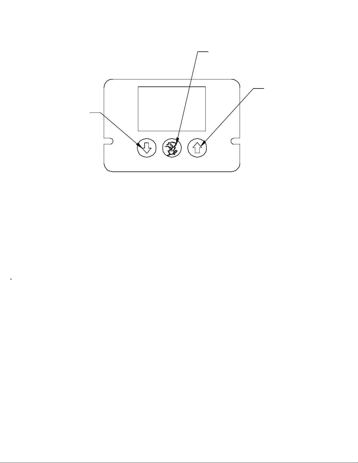
OPERATING INSTRUCTIONS
CENTER BUTTON
HOLD DOWN FOR 5
SECONDS TO ENTER
PROGRAM MODES
LEFT BUTTON:
TOGGLE TEMP DOWN
IN PROGRAMMING MODE
MONITOR UPPER TANK TEMP
IN NORMAL OPERATING MODE
FACTORY DEFAULT TEMPERATURE SETTING IS 200 DEGREES F
TO ADJUST TEMPERATURE SETTING:
1. DEPRESS AND HOLD CENTER BUTTON FOR 5 SECONDS UNTIL
'prog' APPEARS
2. TOGGLE TEMPERATURE SETTING UP OR DOWN WITH ARROWS
3. DEPRESS CENTER BUTTON, 'end' WILL APPEAR
4. DEPRESS LEFT OR RIGHT BUTTON TO EXIT PROGRAM MODE
TEMPERATURE SETTING WILL BE STORED
RIGHT BUTTON:
TOGGLE TEMP UP
IN PROGRAMMING MODE
MONITOR LOWER TANK TEMP
IN NORMAL OPERATING MODE
TO MONITOR UPPER AND LOWER WATER TEMPERATURE LEVELS:
1. DEPRESS LEFT ARROW TO MONITOR UPPER TANK TEMPERATURE
2. DEPRESS RIGHT ARROW TO MONITOR LOWER TANK TEMPERATURE
TO CHANGE FROM FAHRENHEIGHT TO CENTIGRADE TEMP DISPLAY:
1. UNPLUG POWER CORD
2. DEPRESS AND HOLD CENTER BUTTON, WHILE HOLDING BUTTON
PLUG POWER CORD BACK IN
3. WHEN 'prog' APPEARS TOGGLE F TO C WITH LEFT OR RIGHT BUTTONS
4. DEPRESS CENTER BUTTON TWICE UNTIL 'end' APPEARS
5. DEPRESS LEFT OR RIGHT BUTTON TO STORE SETTING AND EXIT PROGRAM MODE
NOTE: A THERMOMETER ICON IS DISPLAYED WHEN THE HEATER IS ENERGIZED
A "HAPPY FACE" ICON IS DISPLAYED WHEN TEMPERATURE SETPOINT IS REACHED
4
Page 5

PLUMBING AND ELECTRICAL
COMPONENTS
17
13
9
12
11
10
6
7
8
16
15
4
5
1
14
3
2
5
Page 6

PLUMBING AND ELECTRICAL COMPONENTS (CONT)
FIGURE # QTY. PART # DESCRIPTION
1 1 104113 FAUCET-HI HEAT
2 1 104114 NUT-HI HEAT FAUCET
3 1 800236 FITTING, TEA FAUCET
4 1 104118 FITTING -EXTENSION,
FAUCET
5 1 800244 GASKET-NYLON
.671*.937*.062
6 1 104111 VALVE ASSY-HOT
WATER
7 1 100155 CONNECTOR-MALE ¼ C X
1/8 NPT WITH NUT
8 1 104135 TUBE-COPPER INLET
9 1 511053 BLOCK-TERMINAL
120/240V
10 1 104117 TUBE ASSY-OVERFLOW
11 1 120256 BOARD-LIQUID LEVEL
12 1 111684 TRIAC-40 AMP, 600V
13 1 121659 HEATSINK
14 1 104109 TANK-HOT WATER
15 1 705002 LIMIT,66TM DPSTC 40A
16 1 120275 BOARD-LIQ CRYSTAL,
HOT WATER
6
Page 7
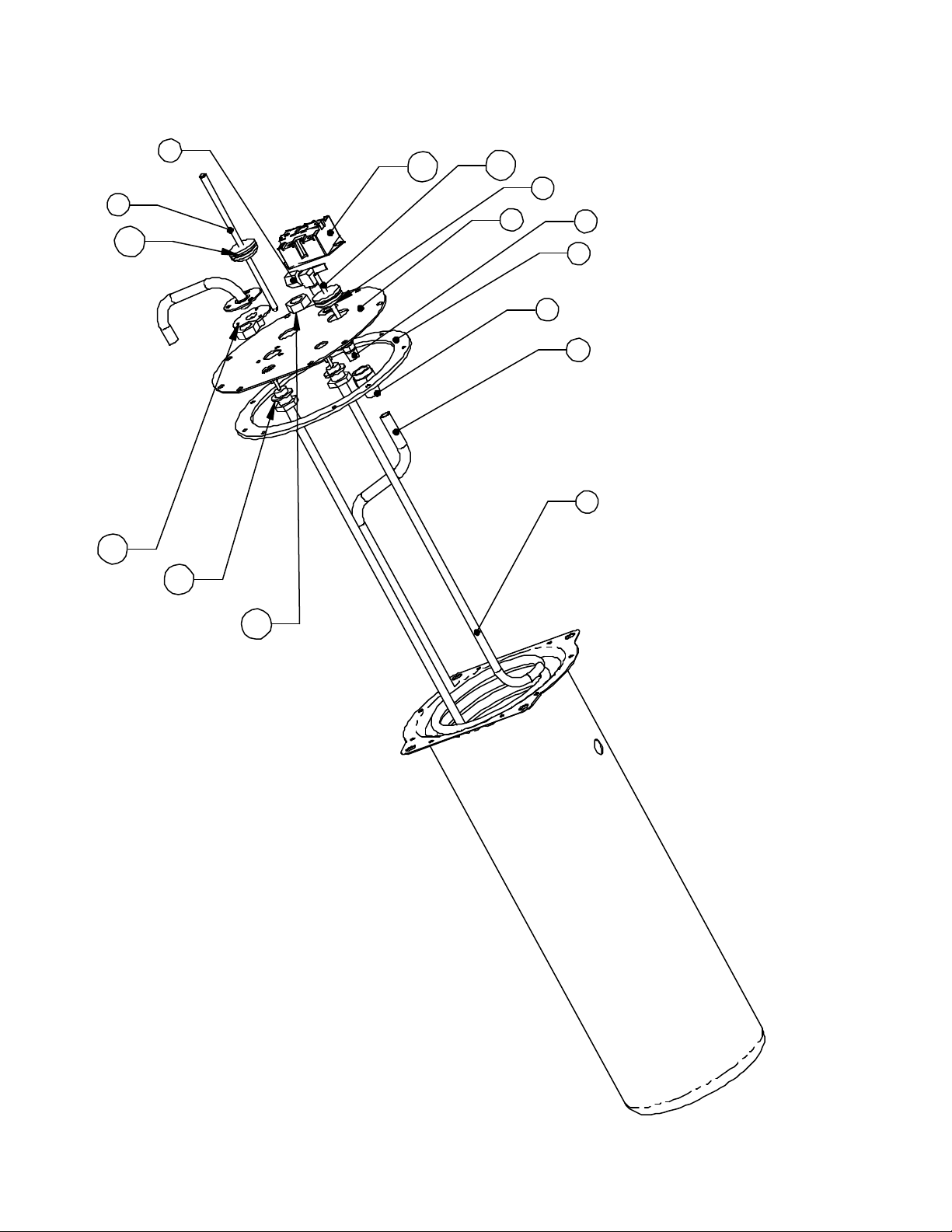
WATER TANK
3
10
14
9
13
12
15
ASSEMBLY
7
1
8
2
6
4
5
11
7
Page 8

WATER TANK ASSY (CONT)
FIGURE # QTY. PART # DESCRIPTION
1 1 104108 LID-SPOTWELD
HOT WATER
2 1 704221 GASKET-TANK SILICONE
3 1 151677 PROBE-DUAL
THERMISTOR
4 1 102019 TUBE-WATER INLET
5 1 701286-10 ELEMENT, DUAL
VOLTAGE 1350W/5500W
6 1 100431 NUT-BRASS 9/16-24
7 2 100030 GASKET-BRASS .566 ID
8 1 101720 CONNECT FM 3/C X 1/8
NPT
9 1 100149 ELBOW -1/4C 90 DEG W
NUT
10 1 704222 GASKET-SILICON 3 HOLE
11 2 100190 NUT-1/2-20 JAM, BRASS
12 1 705002 LIMIT, HI, 40 AMP
13 2 100409 GASKET-BRASS .520 ID
14 2 102836 GROMMET-SILICON
15 1 705071 PROBE-2”
8
Page 9

FLOAT SWITCH
ASSY-HI TEMP
PN 110890
FLOAT SWITCH ASSEMBLY
DRIP TRAY
BRACKET-FLOAT
SWITCH
PN 151761
DRIP TRAY
GRATE
PN 104134
DRIP TRAY
PN 1041339
9
Page 10

Service Notes
1) Should water overflow the tank into the float switch, the water fill valve
(solenoid) circuit is interrupted. This is a safety feature to prevent as spill from
occurring should the water level-probe system malfunction (ER6). To empty the
overflow cup, unplug the power cord and loosen screw on the sheet metal cup
holder bracket. (see illustration on page 9) and empty cup.
2) The heater element is protected by a hi-limit manual reset thermostat (ER5).
Error Modes - To reset an error condition simply power the machine off and
back on. If the error continues, check the condition of all sensors,
hardware & wiring.
ER1 – Top thermistor shorted
ER2 – Top thermistor open
ER3 – Bottom thermistor shorted
ER4 – Bottom thermistor open
ER5 – Heater has run for more than 45 minutes continuously
ER6 – Fill time has run for more than 6 minutes
Newco Enterprises, Inc. * 1735 South River Rd. * P.O. Box 852 * St. Charles, MO 63302
10
Page 11

RD/WH
OPTIONAL
BK
BK
WH/RD
11
WH/RD
BK
BK
 Loading...