

Page 1

1
Page 2

Contents
FEATURES/ SPECIFICATIONS...........................................................................4
NEWCO PRODUCT WARRANTY........................................................................4
ITEMS INCLUDED WITH MACHINE....................................................................5
EQUIPMENT START-UP PROCEDURE..............................................................7
EQUIPMENT CALIBRATION................................................................................7
SANITATION.......................................................................................................11
PROGRAMMABLE BUTTONS ...........................................................................13
PRODUCT RATIO...............................................................................................15
PORTION CONTROL .........................................................................................16
MANUAL DISPENSE..........................................................................................17
HOT / COLD WATER SELECTION ....................................................................18
WHIPPER MOTOR ENABLE/DISABLE..............................................................19
BAG TRACKING.................................................................................................20
BAG TRACKING RESET....................................................................................21
SERVICE – CALIBRATION AND TROUBLESHOOTING...................................22
TEMPERATURE ADJUSTMENT............................................................22
CABINET ACCESS.................................................................................23
HOT & COLD (AMBIENT) WATER CALIBRATION ................................25
TROUBLESHOOTING ............................................................................28
REPLACEMENT PARTS.........................................................................29
WATER TANK HEATING........................................................................31
WHIPPER & PUMP ASS’Y......................................................................32
WHIPPER & PUMP MOTORS................................................................33
DUMP VALVES.......................................................................................34
DISPLAY BOARD ERROR MESSAGES ................................................35
2
Page 3
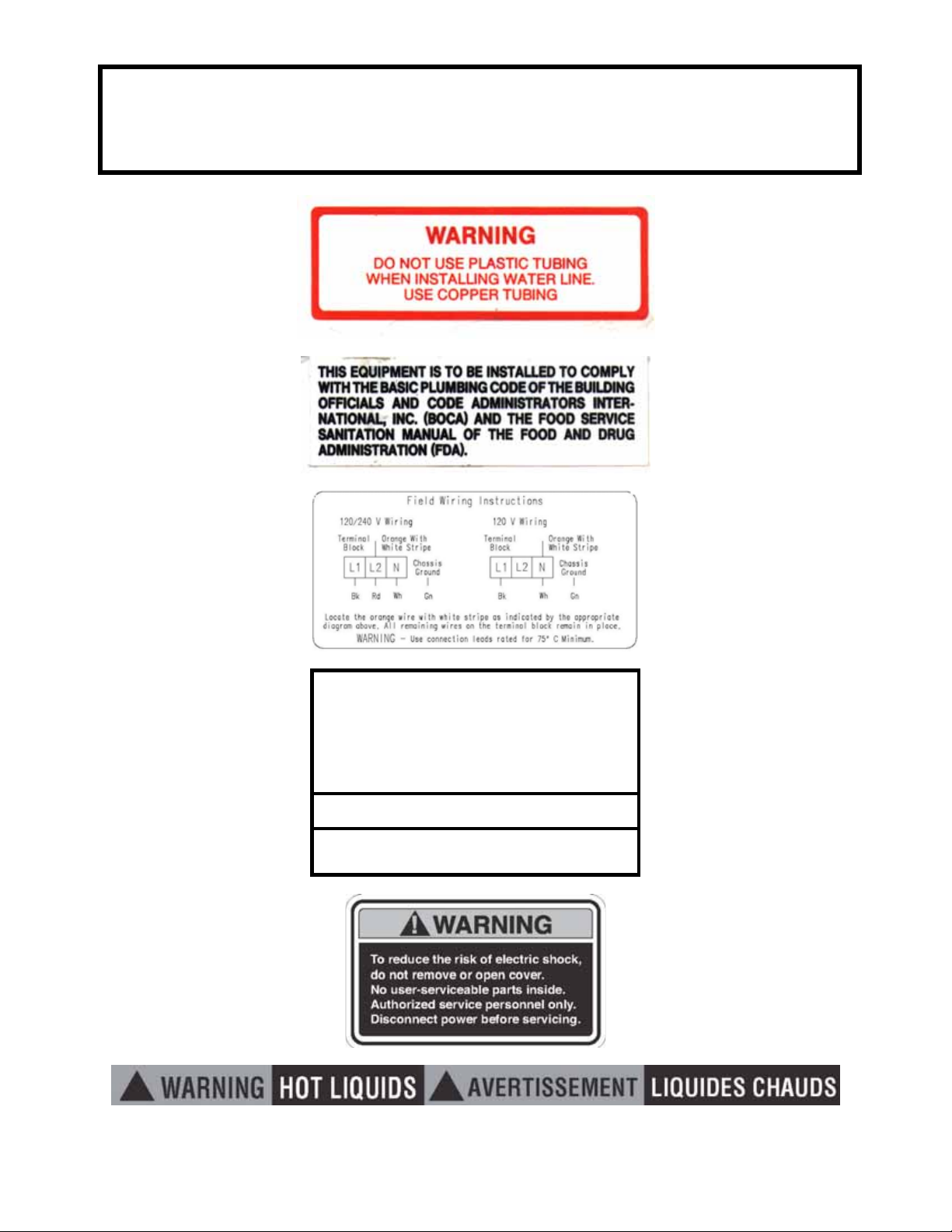
NOTICE: Read and follow all notices posted on this machine.
Do not damage or destroy these notices as they are for your
protection
! WARNING
DO NOT OVERLOAD CIRCUIT.
ALWAYS ELECTRICALLY GROUND THE
CHASSIS OR ADAPTOR PLUG.
DO NOT DEFORM PLUG OR CORD.
FOLLOW NATIONAL AND LOCAL ELECTRICAL
CODES.
KEEP COMBUSTIBLES AWAY.
FAILURE TO COMPLY RISKS EQUIPMENT
DAMAGE, FIRE OR SHOCK HAZARD.
READ THE ENTIRE OPERATING MANUALBEFORE
USING THIS PRODUCT
3
Page 4

MCM-3-COMBO
Features/ Specifications
• Product to Water Ratio Range: 1.5:1 to 35.0:1
• Cup Volume Range: 1.5 oz to 25.0 oz
• Hot Water Temperature Range: 160 to 190 deg F
• Concentrate Calibration Range: 2.5 oz to 10.0 oz
• Water Calibration Range (Hot or Cold) 13.0 oz to 25.5 oz
• Initial fill Timeout: 10 Minutes
• Fill Timeout: 40 Seconds
• Automatic Sanitation-Sanitation cycles at power up when water
temp reaches 160 degrees, 1 hour after last product dispensed,
and 24 hours after the last sanitation cycle
• Electrical Specifications-120V 1500W 1ph / 240V 6000W 1ph
Newco Product Warranty
Newco warrants equipment manufactured by it for 90 days labor- 1 year parts.
These warranty periods run from the date of installation Newco warrants that the
equipment manufactured by it will be commercially free of defects in material and
workmanship existing at the time of manufacture and appearing within the
applicable warranty period. This warranty does not apply to any equipment,
component or part that was not manufactured by Newco or that, in Newco’s
judgment, has been affected by misuse, neglect, alteration, improper installation
or operation, improper maintenance or repair, damage or casualty. This warranty
is conditioned on the Buyer 1) giving Newco prompt notice of any claim to be
made under this warranty by telephone at (800) 556-3926 or by writing to PO Box
852, Saint Charles, MO 63302; 2) if requested by Newco, shipping the defective
equipment prepaid to an authorized Newco service location; and 3) receiving
prior authorization from Newco that the defective equipment is under warranty.
THE FOREGOING WARRANTY IS EXCLUSIVE AND IS IN LIEU OF ANY OTHER
WARRANTY, WRITTEN OR ORAL, EXPRESS OR IMPLIED, INCLUDING, BUT NOT
LIMITED TO, ANY IMPLIED WARRANTY OF EITHER MERCHANTABILITY OR
FITNESS FOR A PARTICULAR PURPOSE. The agents, dealers or employees of
Newco are not authorized to make modifications to this warranty or to make
additional warranties that are binding on Newco. Accordingly, statements by
4
Page 5

such individuals, whether oral or written, do not constitute warranties and should
not be relied upon.
If Newco determines in its sole discretion that the equipment does not conform to
the warranty, Newco, at its exclusive option while the equipment is under
warranty, shall either 1) provide at no charge replacement parts and/or labor
(during the applicable parts and labor warranty periods specified above) to repair
the defective components, provided that this repair is done by a Newco
Authorized Service Representative; or 2) shall replace the equipment or refund
the purchase price for the equipment.
THE BUYER’S REMEDY AGAINST NEWCO FOR THE BREACH OF ANY
OBLIGATION ARISING OUT OF THE SALE OF THIS EQUIPMENT, WHETHER
DERIVED FROM WARRANTY OR OTHERWISE, SHALL BE LIMITED, AT NEWCO’S
SOLE OPTION AS SPECIFIED HEREIN, TO REPAIR, REPLACEMENT OR REFUND.
In no event shall Newco be liable for any other damage or loss, including, but not
limited to, lost profits, lost sales, loss of use of equipment, claims of Buyer’s
customers, cost of capital, cost of down time, cost of substitute equipment,
facilities or services, or any other special, incidental or consequential damages.
Items Included with Machine
Drip tray Ass’y w/Drain Hose Qty 1
Water Filter w/Hardware & Shutoff Qty 1
Florescent Bulbs Qty 2
Durotrans Translucent Door Sign Qty 1
4” Plastic Legs Qty 4
5
Page 6

Machine Set-Up
NOTE: The MCM-Combo machine weighs approximately 100 LBS . Use more than
one person when unpacking and lifting machine. DO NOT LIFT BY THE DOOR.
See illustrated machine set-up guide supplied with equipment.
1. Remove the box containing the accessories listed above. Open and
remove the 4” plastic legs and the drain pan, drain pan housing (black),
and the drain pan support with hose. Once equipment is out of the box,
install the 4” plastic legs to the base of the machine. Note: The front legs
and drain support bracket must be installed at the same time. Align
bracket holes with the holes in the front of the machine base, and secure
by screwing the plastic legs tightly against bracket. The 4” legs are
designed to hold the drain support bracket to the base of the machine. The
drain bracket has an 6’ drain hose attached for hookup. Place equipment
at final location and plumb in the drain line. Note: The equipment must be
plumbed to a drain because of the Automatic Sanitation System Feature of
the machine.
2. Install the two (2) florescent bulbs in the door face and rotate ¼ turn to seat
in socket. Unscrew and remove the three (3) brass screws in the inside top
of the door panel and remove door cap. Remove the translucent durotrans
sign from the protective cardboard sleeve, remove protective film from
both sides of sign, and install by sliding the sign panel from the top of the
door opening down following the slide guides until the sign is seated at the
bottom of the guides. Re-seat door cap and secure with the three (3) brass
screws.
3. This equipment is shipped with a water filter. Before installation unscrew
the blue top ass’y, remove the filter cartridge and remove the ‘plastic wrap’.
Re-assemble and follow the ass’y instructions provided with the filter.
Install the water filter bracket (use 2 #8 screws) on either side of water line
connection, upper rear center of machine, and install water filter &
connections to the to the water inlet outlet located in upper rear of
Machine. Note: Pre-flush filterand water lines before connecting to
equipment water inlet.
4. Connect free end of plain water lines to water supply. Note: This equipment
is to be installed to comply with the applicable Federal, State, or local
plumbing codes having jurisdiction. Flow requirements: Minimum flowing
pressure of 35 PSIG (2.46 kg/cm 2, 2.41 BAR) Maximum static pressure of
100 PSIG (7.02 kg/cm 2, 6.85 BAR) Provide enough extra coiled tubing (at
least 2x the depth of the unit) so that the machine can be moved for
cleaning underneath.
5. Turn on water supply and check for leaks.
6
Page 7

Equipment Start-Up Procedure
1. Plug machine into electrical supply [120V, 1.8 KW, 15A,] [240V, 3 poles, 4
wire grounding type Twist-Plug Receptacle. For 240V units, Use L6-20R or
L6-30R, 2 pole, 3 wire Twist-Plug Receptacle]. Hot water tank will start
filling.
2. Activate the Light switch (Toggle Up) located on the inside of the door.
3. The LCD window will display self-test message briefly, sanitation indicators
will light (will not sanitize until tank reaches 160 deg). (The sanitation cycle
can be cancelled by pushing the Rinse/Auto-Rinse button).
4. Allow approximately 6-8 minutes for the tank to fill. If the tank does not fill
up within the first 10 minutes an error message will appear in the LCD
window FIL. (See Definition of Screen and Troubleshooting Guide). The
machine is factory preset to dispense water at the rate of 20-25 oz. /30 sec.
For hot water & 30-32 OZ. /30 sec. for cold water.
5. Allow up to 50 minutes for the water to reach a temperature of 175°F. The
heat up time will depend on the water inlet temperature, the input voltage.
6. This unit is equipped with a pump safety interlock switch activated by
opening and closing the door. When door is open, concentrate pumps will
not operate.
7. Set-up and calibrate the Moo Products for each channel while the machine
is heating.
Equipment Calibration
Machine Hot & Cold water volumes have been pre-set at the factory. These
volumes have been programmed into the software. It is necessary however to
calibrate the Product Concentrate for each dispense channel in order for the
machine to allow digital calibration of correct Water to Product Ratio.
Moo Concentrate Milk Products will dispense 6-9 ounces of product within 30
seconds, depending on product flavor, as each product blend has slightly
different viscosities.
When machine is equipped with “Coffee Kit” liquid coffees will dispense in 3-5
oz/30 sec. ranges
7
Page 8
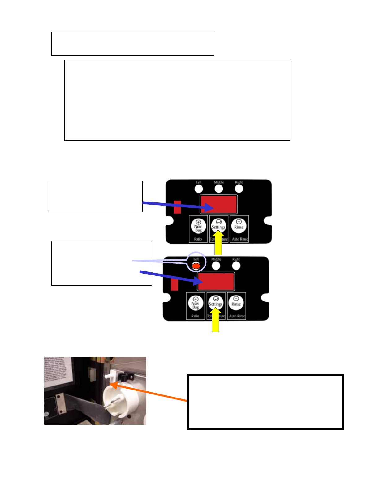
Product Calibration Instructions
Overview: Machine H2O settings are calibrated at the factory and
normally do not need adjustment. Concent rate calibration
should be performed at initial machine set-up, and each
time the product density (or viscosity) changes.
(If same product is used, I.e. just changing out an empty box
of the same product, channel does not need recalibration)
Should it become necessary to re-calibrate H2O settings,
see page 25
Step 1
Press & hold Button 2 “Setting s”
After approximately 5 seconds
Display will change to”- - -”
---
Step 2
Continue holding for approximately
8 more seconds until display
Changes to “Con” and “Left”
Channel indicator is displayed
Release Button 2
con
Note: Pull out safety switch on door during
product calibration cycle. If switch is not
pulled out to ”on” position the pumps will
not operate, and an error code will flash,
“P1, P2, or P3”
8
Page 9
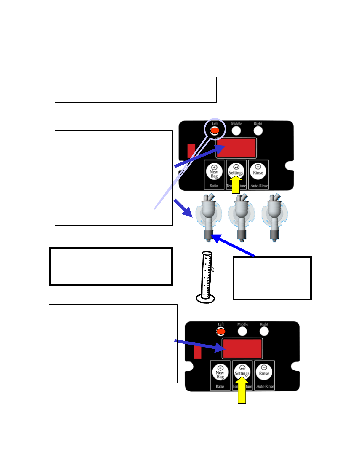
Product Calibration Instructions-Cont’d
Step 3
Depress button 2 (Settings)Display will change to” 0:30”
Place a measuring cup
(preferably a graduated cylinder)
under the dispensing head to be
Calibrated ( as indicated by
channel light)
0:30
If graduation is
in Millimeters, divide by 28.36
to convert to ounces
Step 4
Press button 2 agai n , machi n e will
pump concentrate into measuring cup for
30 seconds-When concentrate stops,
read concentrate volume (in ounces) from
cup.
Toggle buttons
Until measured value is displayed.
1(+) & 3(-)
Remove nozzle when
calibrating
concentrate. Replace
when finished.
7.5
9
Page 10
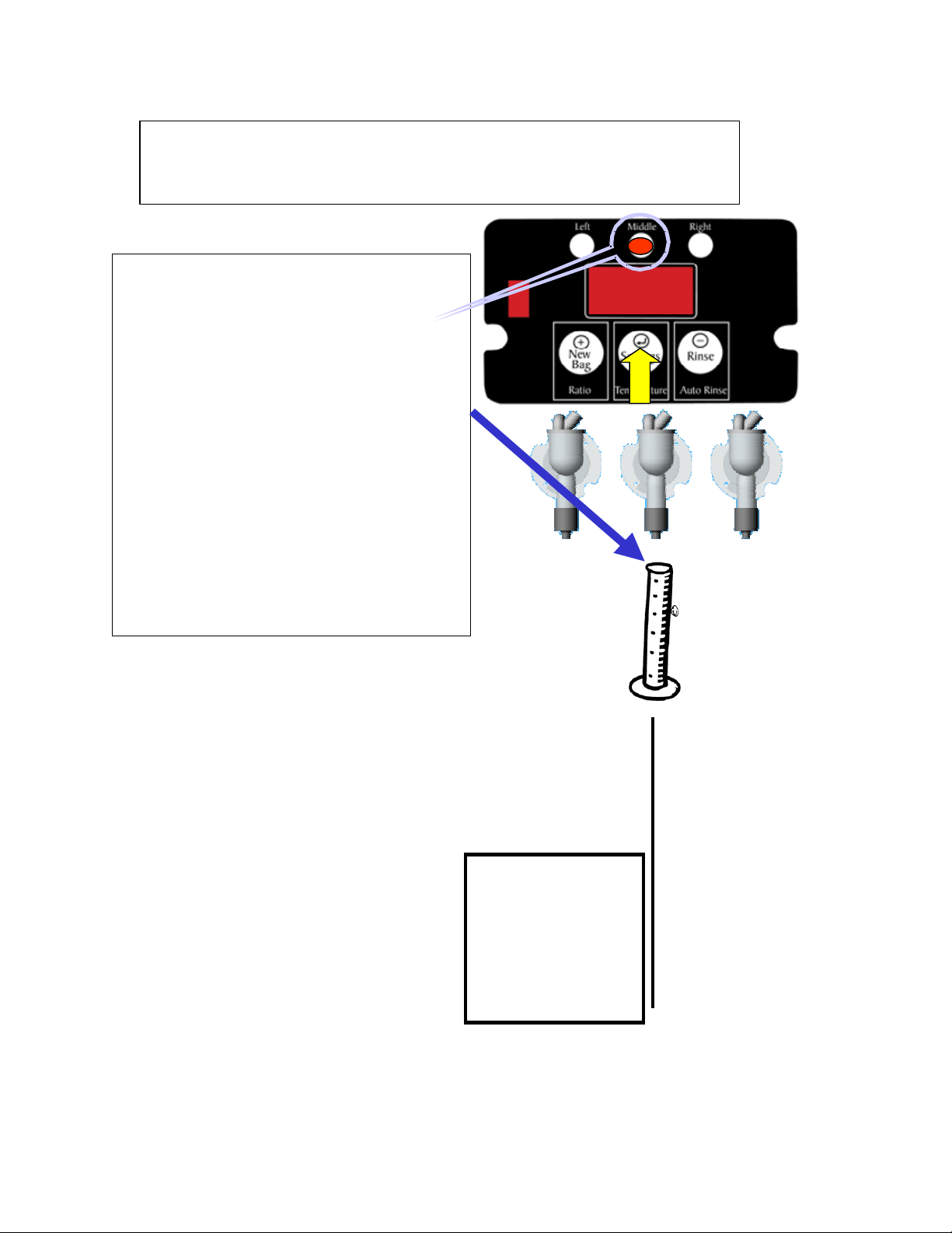
Product Concentrate Calibration Instructions
-
Cont’d
Step 5
Press center button to store settings,
Display will change to 0:30 and
Indicator light will move to Middle
button on display
Move the graduated cylinder (at
least 8 fl oz) under the Middle
Dispensing head, repeat steps 3 - 5
For Middle and Right Dispense
Heads
When Right dispense info is
Stored, display turns blank &
returns to operating mode
0:30
A graduated
cylinder or
Brixing cup will
assure accurate
calibration of
product
concentrate
10
Page 11

Sanitation
Automatic Sanitation Cycle:
Sanitation cycle waits for water temp to reach 160 deg F. min.
Sanitation cycles are performed at power up, 1 hr after the
Last product dispense, and 24 Hrs after the last sanitation cycle.
Once a 24 Hr sanitation cycle has been performed, no more
sanitation cycles will take place until initiated by a dispense or
another power-up.
Sanitation cycle lasts for approx 6 seconds, all three hot water
dispense valves open and the whipper motors run. Sanitation
cycle may be cancelled by pressing any button on the display
board.
Sanitation cycle can be manually initiated by pressing the right
button on the display board. Cleaning cycle will initiate as above.
Cleaning & Sanitizing Instructions:
TSanitizingTT: All food dispensing units should be sanitized periodically. All parts
to be sanitized must be cleaned first.
To prepare a sanitizing solution: ADD 2 TSP. OF LIQUID CLOROX BLEACH (5.25%
CONCENTRATION) TO 1 GALLON OF WATER AT
ROOM TEMPERATURE (70°- 90°F).
Note: Always start with an unopened bottle of Clorox Bleach since the solution
from an opened bottle has a short life span.
• Soak all parts for a minimum of 3 min. in the sanitizing solution.
• Let all sanitized parts drain and dry naturally. DO NOT WIPE THEM DRY.
• Before using the sanitized unit (or parts) with foodstuffs, rinse all parts
thoroughly with water.
Water pipe connecting and fixtures directly connected to a potable water supply
shall be sized, installed, and maintained in accordance with
Federal, Sate, and Local codes (section 7).
11
Page 12

Cleaning & Sanitizing Instructions-cont’d
Cleaning
1. Remove the drip tray with grill and empty the contents.
2. Wash and let dry the tray and grill (use a mild dishwasher detergent).
3. Wash and let dry the dispense area.
4. Turn the power switch to ON.
Manually Flushing the Whipper Chambers
1. Open the cabinet door.
2. Place a container under each dispense nozzle and push the Auto Rinse button.
Removing and Cleaning the Whipper Chambers
1. Remove the dispense cap by pulling it upward.
2. Grab and twist the whipping chamber clockwise and pull it off the
mounting plate.
3. Pull the whipper blade off the motor shaft. Notice the flat keyway on the
shaft and the matching keyway inside the whipper blade shaft. It is
important that these two keyways are lined up when re-assembling the
components.
4. Slip off the slinger washer from the whipper chamber mounting plate.
Clean slinger washer, whipper blade, motor shaft, whipper housing and
dispense cap.
5. Reinstall making sure slinger washer is within 1/32” of whipper seat, but
not touching whipper seat. (See illustration below and on page
25HHH32)
12
Page 13

Programmable Buttons
(3 per channel)
TTA. Manual DispenseTT-“Push & Hold” center button for manual dispensing
Example: Program the center button to manually dispense once drink per channel.
Disable outer buttons on each channel.
26H HHSEE PAGE 17
Indicates buttons that have been disabled
Buttons Enabled
13
Page 14

Programmable Buttons Cont’d
TTB. Portion ControlTT-Ability to set a volume dispense (in ounces) for any button
Example: Program the 1PP
the center button for a large cup dispense, and the 3PP
st
PP
button for each dispense for a small cup dispense,
rd
PP
button for a
manual dispense HH27HSEE PAGE 16
All Buttons Enabled
C. Hot/Cold Water Dispense-Ability to have hot or cold (ambient)
dipsense choice per button
Example: Pr ogram t he 1
st
& 3rdbutton s on each chan nel “Hot” & “I ced”
Center Buttons Disabled
HH28HSEE PAGE 18
14
Page 15

Product Ratio
Multi Level Programming
Step 1
Press and hold until display
changes to
Step 2
Press and hold until display
changes to
rAt
Step 3
Press Button to be
Programmed-Display will
change to a Ratio Value
Water:Product RATIO
Step 4
Toggle Ratio Value + or –
When desired ratio value is
obtained press center button
3.0
Ratio valu e is now locked in for
button-Display changes to
rAt
Repeat step 3&4 for remaining
buttons
15
Page 16

Portion Control
Multi Level Programming
Step 1
Press and hold until display
changes to
Step 2
Press and hold until display
changes to
Por
Step 3
Press Button to be
Pr o g r am med-D i s play wil l
change to a Ounce Volume
Value
Portion Control
Step 4
Toggle Volume Value + or –
When desired Volume (ounce)
value is obtained press cen ter
button.
Portio n Control is now locked in
3.0
for button-Display changes to
Por
Repeat s tep 3&4 for rem aining
buttons
16
Page 17

Step 1
Press and hold until display
changes to
Step 2
Press and hold until display
changes to
Manual Dispense
Multi Level Programming
Button-Manual Dispense
Enable/Disable
Step 4
Toggle Ounce Volume Value (–)
Por
Step 3
Press Button to be
Programmed-Display will
change to an Ounce Volume
Value
3.0
until display
Reads “on” or “off”(+)
on
If “off” is selected button is disabled
If “on” is selected button is set for
Manual Dispense
Press center button to store settings for
selected button
Repeat step 3&4 for remaining buttons
off
17
Page 18

Hot / Cold Water Selection
Multi Level Programming
Step 1
Press and hold until display
changes to
Step 2
Press and hold until display
changes to
o
F
Step 3
Press Button to be
Programmed-Display will
change to Temp Option
Hot/Cold Water Selection
Step 4
Press either button
to toggle “hot” or “cold (ambient)” water
temperature
Hot
Press center button to store button selection
Cl d
Hot
Temp choice is now locked in for button-Display changes
to
o
F
Repeat step 3&4 for remaining buttons
18
Page 19

Whipper Motor Enable/Disable
Step 1
Press and hold until display
changes to
Step 2
Press and hold until display
changes to
Multi Level Programming
Whipper Motor
Enable/Disable
Step 4
bln
Step 3
Press Button to be
Programmed-Display will
change to “on” or “off”
on
Toggle “on” “off” + or –
Center Button stores last value
displayed
Repeat step 3&4 for remaining
buttons
19
Page 20

Bag Tracking
Multi Level Programming
Bag Tracking Enable/Disable
Step 1
Press and hold until display
changes to
bag
Step 4
Step 2
Continue holding until
display changes to
btr
Step 3
Pressing Left or Right
buttons toggles channel
indictator to select channel
To Enable/Disable
Pressing middle button
changes display to
on
Step 5
Pressing Left or Right buttons toggles
display“on” or “off”
Pressing Middle Button
Stores “on” or “off” setting for
indicated channel
Repeat step 3-5 for other channels
Note: Bag Tracking
cannot be used when
more than (1) ratio is
programmed in the
same channel
20
Page 21

Bag Tracking Reset
Bag Tracking Reset
Step 1
Press and hold for 1 second-
display changes to
bag
Step 2
Pressing Left , Middle or
Right buttons will reset the
bag count to full for
corresponding channel
Left Middle Right
Note: When indicator
light remains
steady, buttons are
disabled until
Channel is reset
21
Page 22

Service – Calibration and Troubleshooting
Temperature Adjustment
Temperature Adjustmen t
Step 1
Press and hold until displa y
changes to
Step 2
Release and repress Middle
Button-display changes to
180
Hot Water Tank
Step 3
Toggle Te mperature Value + or –
When desired Temperature value
is obtained press center button to
store
Note: Middle Indicator Light will
turn on if Tank is Heating
22
Page 23

Service – Calibration and Troubleshooting
Cabinet Access
POWER PANEL & VALVE ACCESS
Lift up &
Remove LH side panel
23
Page 24

Service – Calibration and Troubleshooting
Cabinet Access Cont’d
Machine Panel Removal
Component Access
2. LIFT & REMOVE
BACK PANEL
3. LIFT AND REMOVE SIDE PANEL
1. REMOVE
BRASS
THUMBNUTS
(4) PL
FROM INSIDE
MACHINE
LIFT & REMOVE
TOP PANEL
24
Page 25

Service – Calibration and Troubleshooting
OW
Hot & Cold (Ambient) Water Calibration
H2O Calibration Instructions
H2O Calibration applies to the following :
A. Hot Water flow rate
B. Cold Water (ambient) flo w rate
Calibratio n routine-Note: H2O Calibratio n is a factory
setting & should not need re-calibration unless
A dispensing valve is replaced o r t h e mea sured
dispense volume does not match the displayed set ting
NOTE: MACHINE MUST BE AT OPERATING TEMPERATURE PRIOR
TO CALIBRATING HOT WATER FL
Step 1
Press & hol d Bu t ton 2 “Settings”
After approximately 5 seconds
Display will change to”- - -”
Step 2
Continue holdi ng for approximately
8 more seconds until display
Changes to “con”. Do not release
button, after approx 8 more seconds
Display will ch an g e to “H2 o ”
RATE.
---
H2o
25
Page 26

Service – Calibration and Troubleshooting
Hot & Cold (Ambient) Water Calibration Cont’d
H2O Calibration Instructions-Cont’d
Calibration routine-Hot Water
Step 3
(See hot water calibration
note on previous page)
Depress button 2 (Settings)Display will change to” 0:30”
Place a measuring cup (at least
32 fl oz) under the left dispensing
head (and as shown by indicator
light)
0:30
Step 4
Press button 2 ag ain, mach ine will
Dispense water into measuring cup for
30 seconds-When water stops, read
water volume (in ounces) from cup.
Toggle buttons
Until measured val u e is displ ayed .
1(+) & 3(-)
24.5
26
Page 27

Service – Calibration and Troubleshooting
Hot & Cold (Ambient) Water Calibration Cont’d
H20 Calibration Instructions-Cont’d
Calibration routine-Hot Water
Step 5
Press center button to store settings,
Display will change to 0:30 and indicator
Light will move to Middle button on
display
Move the measuring cup (at least
32 fl oz) under the Middle
Dispensing head, repeat steps 3-5
For Middle and Right Dispense
Heads
0:30
When Right dispense info is
Stored Display changes to “cld”,
see step 6
H2OCalibration routine-Cold (Ambient) Water
Step 6
H2O Calibration is Bypassed
(by toggling “Right” button until
“cld” appears in di sp lay)
cld
Repeat Steps 3-5 for cold (ambient)
values
27
Page 28

Service – Calibration and Troubleshooting
Troubleshooting
PROBLEM PROBABLE CAUSE REMEDY
1. No water a) Water turned off
b) Water line not connected
c) Faulty water inlet valve
2. No water one channel only a) Loose connection @ dispense
valve
b) Loose connector on main board
c) Faulty dispense valve
3. Water not hot a) Temperature setting too low
b) Heater overload tripped
c) Defective heater element
d) Check Triac
4. Water does not shut off a) Liquid level probe malfunction
b) Faulty water inlet valve
5. Drink too strong a) Concentrate calibration settings
incorrect
b) Water to concentrate ratio
incorrect
6. Drink too weak a) Concentrate calibration settings
incorrect
b) Water to concentrate ratio
incorrect
7. Drink not whipped a) No whipper blade
b) Whipper motor connection
c) Whipper motor bad
8. Pump does not turn a) Pump motor connection
b) Pump motor bad
9. Noise coming from whipper a) Whipper chamber not seated
b) Slinger washer pushed on motor
shaft too far.
c) No whipper blade
10. Door light does not light a) No power to machine
b) Faulty lamp bulb
c) Lamp ballast
11. Buttons are flashing a) Machine error
b) Bag empty
12. Buttons do not operate a) Check for Error message
b) Button may be disabled
a) Turn water on –open shutoff
b) Ensure water line is connected
c) Check valve and connections-
a) Check connectors @ dispense
b) Make sure harness is seated
c) Replace dispense valve (PN
a) Adjust temperature setting
b) Reset hi-limit thermostat (see
c) Replace heater element (see
d) Replace Triac (Fig Page
a) Check probe connections (see
b) Check valve and connections-
a) Recalibrate concentrate
b) Adjust ratio (see page
a) Recalibrate concentrate
b) Adjust ratio (see page
a) Install whipper blade
b) Inspect whipper motor
c) Replace whipper motor (Page
a) Inspect pump motor
b) Replace pump motor (Page
a) Reseat whipper chamber-see
b) Check gap at slinger washer
c) Install whipper blade (see
a) Make sure machine is plugged
b) Replace lamp bulb (PN
c) Replace ballast (PN 102064)
a) Check door Display for error
b) Reset bag track(see page
a) Check door Display for error
b) See Button enable section
valve
replace if necessary
valve (see page
29H HH34 )
and locked
102068)
(see operating instructions)
page
30HHH31)
page
page
HH31H31)
33HHH31)
32H HH31 )
replace if necessary
settings (see page
settings (see page
34HHH 8)
HH15)
35H 8 )
HH15 )
connections @ motor and @
board plug-in
HH36H33)
connections @ motor and @
board pug-in
)
whipper cleaning instructions
Page
HH12 )
(see page
page
38H HH12H )
HH39H12 )
in and control board has
power
102062) (page
(page
HH30)
messages- (see page
messages- (see page
page
HH43H17H)
40HHH30 )
41HHH35)
HH21)
HH42H35)
37H HH33H
28
Page 29

Service – Calibration and Troubleshooting
Replacement Parts
Temperature probe 151128
Thermostat-Man reset 111593
Tank Element 705439-10
Triac 111684
Relay-Backup 110908
Cooling Fan 205057
Whipper Motor 102474
Peristaltic Pump Motor 102042
Whipper Blade 102057
Whipper Seal 102049
Slinger Washer 102048
Whipper Base 102047
Whipper Dosing Head 102046
Whipper Chamber 102045
Whipper Restrictor 102044
Pump Housing 102054
Pump Rotor Ass’y 103396
Fill/Ambient Valve 103423
Repair Kit 101527
Dump Valve 102068
Filter Ass’y 103385
Filter Cartridge Replacement 107018
Heating System
Motors / Fan
Plastic Parts
Water System
Drip Tray
Cup Rest 103426
Tubing
Coffee/Espresso Kit 103422
Labels & Lights
Switch Labels 103384
Product Labels 100626
Durotrans Signage 103377
Bulb-Florescent 102062
Electrical Controls
Ballast Board 103378
Display Board 102026
Transformer-Ballast 105115
Transformer-16 Pump 105115-16v
Main board w/whipper 102027
Pump Board 103373
Encoder Board 103374
Switch-Door Safety 103416
Switch-Membrane 102066
29
Page 30

Service – Calibration and Troubleshooting
Replacement Parts Cont’d
Solenoid Manifold
PN 103423
Ballast Board
PN 103378
Bulb-Flourescent, 8W
Dump Valve
PN 102068
(3)
A
Display Board
PN 102026
PN 102062
(2)
Drain Pan w/fitting
PN 103426
Drain Tray Wireform
PN 103426
24 V Transformer
PN 105115
Pump Board
PN 103373
Main Board/Whipper Board
PN 102027
Safety Relay
PN 110908
120/240 Terminal
Block
PN 511053
Line Filter
PN 127178
Drain Tray Housing
PN 103420-BPC
16 V Transformer
PN 105115-16V
DETAIL A
30
Page 31

Service – Calibration and Troubleshooting
Water Tank Heating
Water Tank Ass e mbly
PN 102432- Acccess and Replacement
Parts
Tank Gasket
PN 102221
Cooling Fan
PN 205148
Hi-limit Manual
Reset Thermostat
PN 111593
Heating Element
PN 705439-10
Water Level
Probe
PN 108022
Thermistor
Probe
PN 151128
Remove Brass
Thumbscrews
in Compartment
Upper Rear
Lift and Remove
Back Panel
Remove Nuts
& Bracket to
Remove Tank
Page 88
Welded Tank
with Studs
PN 103322
Triac
PN 111684
31
Page 32

Whipper Ass'y
102063
Service – Calibration and Troubleshooting
Whipper & Pump Ass’y
Rotor Ass'y
3396
PN 10
Whipper Chamber
PN 102045
Whipper Dosing Head
PN 102046
Whipper Restrictor
PN 102044
Pump Housing
PN 102054
Whipper Blade
PN 102051
Whipper Seal
Slinge r Washer
PN 102048
PN 1020 49
Whipper Base
PN 1020 47
32
Page 33

Service – Calibration and Troubleshooting
Whipper & Pump Motors
Pump Motor Spacer
PN 102043
(4)
Pump Motor
PN 102042
Whipper Motor
Whipper Motor
PN 102060
PN 102060
Whipper Motor Spacer
PN 102060
(2)
33
Page 34

Service – Calibration and Troubleshooting
Dump Valves
H2O (Hot) Flow Control Valves
A
Flow Rate Adjustments:
Clockwise-Decreases Flow
Counter Clockwise- Increases Flow
34
Page 35

Service – Calibration and Troubleshooting
Display Board Error Messages
Note: Unplug, re-plug machine, if error does not go away see cause or fix column
Message Meaning
d1.O Dump 1 open circuit Main board / No fix
d2.O Dump 2 open circuit Main board/ No fix
d3.O Dump 3 open circuit Main board/ No fix
b1.O Whipper 1 open circuit Fuse/Whipper board
b2.O Whipper 2 open circuit Fuse/Whipper board
b3.O Whipper 3 open circuit Fuse/Whipper board
P1.O Pump 1 open circuit 16V supply/Pump board/Door
Switch
P2.O Pump 2 open circuit 16V supply/Pump board/Door
Switch
P3.O Pump 3 open circuit 16V supply/Pump board/Door
Switch
F.O Fill Solenoid open circuit Fuse/Pump board
AL.O Ambient Left Solenoid 1 open circuit Pump board/ No fix
AC.O Ambient Ctr Solenoid 2 open circuit Pump board/ No fix
Ar.O Ambient Right Solenoid 3 open circuit Pump board/ No fix
d1.S Dump 1 shorted circuit Main board / No fix
d2.S Dump 2 shorted circuit Main board / No fix
d3.S Dump 3 shorted circuit Main board / No fix
b1.S Whipper 1 shorted circuit Fuse/Whipper board
b2.S Whipper 2 shorted circuit Fuse/Whipper board
b3.S Whipper 3 shorted circuit Fuse/Whipper board
P1.S Pump 1 shorted circuit 16V supply/Pump board
P2.S Pump 2 shorted circuit 16V supply/Pump board
P3.S Pump 3 shorted circuit 16V supply/Pump board
F.S Fill Solenoid shorted circuit Fuse/Pump board
AL.S Ambient Left Solenoid 1 shorted circuit Pump board/ No fix
AC.S Ambient Center Solenoid 2 shorted circuit Pump board/ No fix
Ar.S Ambient Right Solenoid 3 shorted circuit Pump board/ No fix
373 General Error 103373-x pump board Pump Board/Ribbon cable
unplugged
Th.U Thermistor Under value Bad Thermistor/Connection
Th.O Thermistor Over value Bad Thermistor/Tank temp too
high (Boiling)
H.O Heater Open Triac /Relay/Wiring/Main board
H.S Heater Short Triac /Relay/Wiring/Main board
Heater Error Temp. Not rising /Thermistor
/Heater element/Wiring
Fil Fill Solenoid Safety Timeout Fill Valve/Water not turned on
Err General feedback error main board Power-up error/ Wiring/Main
board
bAC Backup driver failure main board Main board/no fix
but Input failure Bad membrane switch/Switch
cable
195 General feedback error main board Main board / No fix
Cause or Fix
35
Page 36

LEFT
+
New
Bag
RATIO
THERMISTER 1
OUT
CN7
MAIN BOARD E2-2521 6
(NEWCO 102027)
WH
BK
1
FUSE
BL
BL
MIDDLE
Setti ngs
RATIO
RD
RD
21
43
GY
OR
BK
OUT
RIGHT
-
Rinse
AUTO
RINSE
OUT
BN
5
109483726
WH
CN1
CN3
DISPLAY BOARD
E2- 25218
NEWCO 102026
CN8
CN4
1 2
WIPPER BOARD
E2- 25201
NEWCO 102028
BK
BK
BK
654
CN1
DUMP VALVE
RIGHT 3
321
SELECTION MEMBRANE SWITCH
WH
GR
BK
CN2
PUMP
MOTOR
RIGHT
654
321
CN1
COLD WATER
SOLENOID
RIGHT
COLD WATER
SOLENOID
CENTER
COLD WATER
SOLENOID
LEFT
SOLENOID
3
CN3
FILL
VAL VE
RED
DOT
BK
WH
OUT
PUMP MOTORS
0-13VDC
PUMP MOTOR BOARD
103374-1
3 PL
YL
WATER
LEVEL
PROBE
TANK
GROUND
CN7
654
CN6
654
CN5
654
PUMP
MOTOR
LEFT
1
654
321
CN3
CN2
CN1
RED
DOT
16VAC XFMR
RIGHT
321
CENTER
321
LEFT
321
PUMP BOARD
103373-2
CN4
21
CN2
PUMP
MOTOR
MIDDLE
654
321
CN1
2
CN3
RED
DOT
CN4
OR
BR
RD
654
SOLENOIDS
321
CN1
GN
THERMISOR
PROBE
TANK
ELEMENT
HI
LIMIT
DUMP VALVE
MIDDLE 2
DUMP VALVE
LEFT 1
WH
BKBKWHBKWH
WHIPPER WHIPPER WHIPPER
GN
MOTOR
MOTOR
1
LEFT MIDDLE RIGHT
N(WH)
N(WH)
MOTOR
2
OR/WH
DOOR
PUMP
CUT/OFF
3
MAIN TERMI NAL BLOCK
SWITCH
BK
L1(BK)
N(WH)
WH
BK
BK
BK
BK
16VAC
TRANSFORMER
PRIMARY
WH
120VAC
BK
LINE
LOAD
BK
SWITCH
WH
FILTER
WH
24VAC
BALLAST
T5 LAMPS
BK
WH
24 VAC
TRANSFORMER
PRIMARY
WH
BK
120VAC
FAN
120VAC
COM
BL
COIL
NO
HEATER BACKUP
RELAY 120VAC
BK/
OR
WH
36
RED
BL
RELAY DRIVER 120 VAC
HOT
SOLIDSTATE
CHASSIS GND
POWER
 Loading...