

Page 1
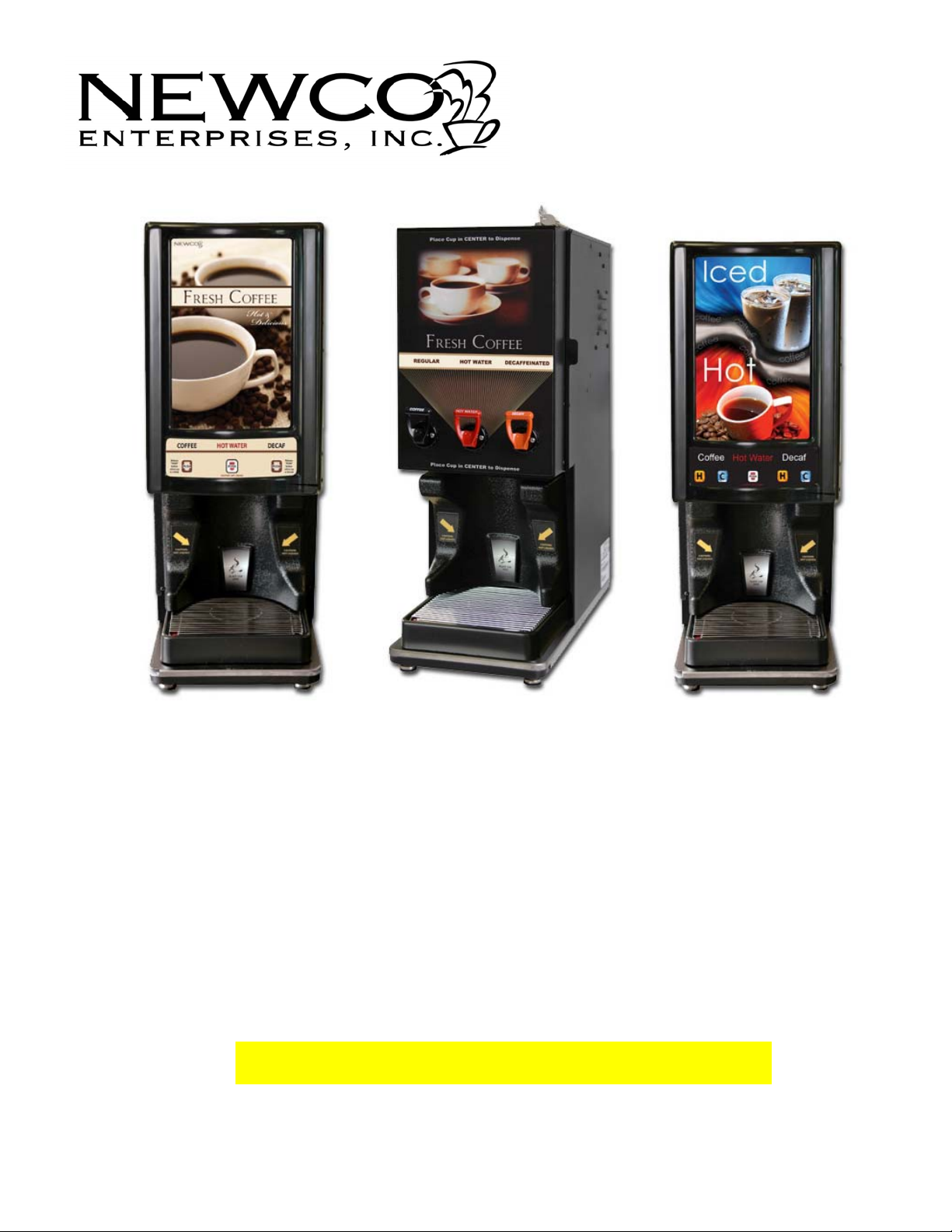
Model LCD-2 (Hot Only)
PN: 120309
Model LCD-2 (Hot Only)
Stainless Front Door
3 Dispensing Handles
PN: 120496
Model LCD-2 Dual (Hot/Cold)
PN: 120441
Installation
And
Programming Guide
LCD-2 By NEWCO Enterprises
Page 2

Section 1 – Installation Instructions and Warranty Policy
Section 2 – Set-Up Programming Instructions
Section 3 – Service Level Programming Instructions
Section 1
Installation Instructions:
Place Machine on a Level Countertop Surface
Connect ¼ Inch Flare water Supply to the Water Inlet located on lower Left Rear of the Machine.
(NEWCO recommends copper tubing for use as water supply to all of our brewing equipment)
Turn water Supply On
Plug or wire brewer to the appropriate voltage circuit as indicated on the serial tag.
Locate power switch on the upper right rear of the machine and turn machine power on.
Machine will begin to fill.
If machine has not filled to probe level within 6 minutes it will enter an error mode. Error code
E-4 will appear on the display screen. To reset the error and resume filling turn power switch
off and then on.
When water in tank reaches probe level, heating cycle will begin.
You are now ready to proceed to Set-Up Programming.
13-May-13 Phone: 1.800.325.7867 Fax: 1.636.925.0029 www.newcocoffee.com
2
Page 3

Section 1
NEWCO PRODUCT WARRANTY
NEWCO warrants equipment manufactured by it for 1-year parts and labor.
These warranty periods run from the date of purchase. NEWCO warrants that the equipment
manufactured by it will be commercially free of defects in material and workmanship existing at the
time of manufacture and appearing within the applicable warranty period. This warranty does not
apply to any equipment, component, or part that was not manufactured by NEWCO or that, in
NEWCO’S judgment, has been affected by misuse, neglect, alteration, improper installation or
operation, improper maintenance or repair, damage or casualty. This warranty is conditioned on the
Buyer: 1) Giving NEWCO prompt notice of any claim to be made under this warranty by telephone at
(800) 556-3926 or by writing to PO Box 852, Saint Charles, MO 63302 2) If requested by NEWCO,
shipping the defective equipment prepaid to an authorized NEWCO service location 3) Receiving
prior authorization, from NEWCO, that the defective equipment is under warranty.
THE FOREGOING WARRANTY IS EXCLUSIVE AND IS IN LIEU OF ANY OTHER WARRANTY,
WRITTEN OR ORAL, EXPRESS OR IMPLIED, INCLUDING, BUT NOT LIMITED TO, ANY IMPLIED
WARRANTY OF EITHER MERCHANTABILITY OR FITNESS FOR A PARTICULAR PURPOSE.
The agents, dealers, or employees of NEWCO are not authorized to make modifications to this
warranty or to make additional warranties that are binding on NEWCO. Accordingly, statements by
such individuals, whether oral or written, do not constitute warranties and should not be relied upon.
If NEWCO determines in its sole discretion that the equipment does not conform to the warranty,
NEWCO, at its exclusive option while the equipment is under warranty, shall either: 1) Provide at no
charge replacement parts and/or labor (during the applicable parts and labor warranty periods
specified above) to repair the defective components, provided that this repair is done by a NEWCO
Authorized Service Representative or 2) Shall replace the equipment or refund the purchase price for
the equipment.
THE BUYER’S REMEDY AGAINST NEWCO FOR BREACH OF ANY OBLIGATION ARISING OUT
OF THE SALE OF THIS EQUIPMENT, WHETHER DERIVED FROM WARRANTY OR
OTHERWISE, SHALL BE LIMITED, AT NEWCO’S SOLE OPTION AS SPECIFIED HEREIN, TO
REPAIR, REPLACEMENT OR REFUND.
In no event shall NEWCO be liable for any other damage or loss, including, but not limited to, lost profits, lost
sales, loss of use of equipment, claim’s of BUYER’S customers, cost of capital, cost of downtime, cost of
substitute equipment, facilities or services, or any other special, incidental, or consequential damage.
13-May-13 Phone: 1.800.325.7867 Fax: 1.636.925.0029 www.newcocoffee.com
3
Page 4
Section 2
Set-Up Programming Instructions:
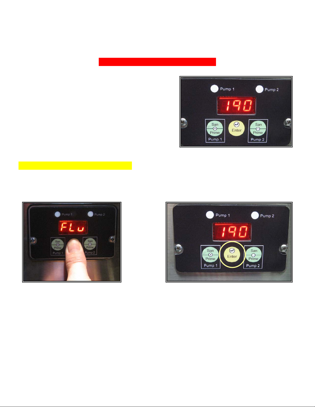
Open machine cabinet door and locate the 3-switch
control panel w/lighted display screen. The temperature
will show on the display screen. As shown in figure 1.
Fig. 1
Step 1. Enter a Programming Mode
Press and hold the center switch labeled “Enter”. After five seconds, the display will flash “Flu”
approximately 13 times. Continue to hold in the switch and the temperature will appear. (Release the
switch when temp. appears on the display.) As shown in figures 2 & 2A.
Fig. 2A Fig. 2
13-May-13 Phone: 1.800.325.7867 Fax: 1.636.925.0029 www.newcocoffee.com
4
Page 5
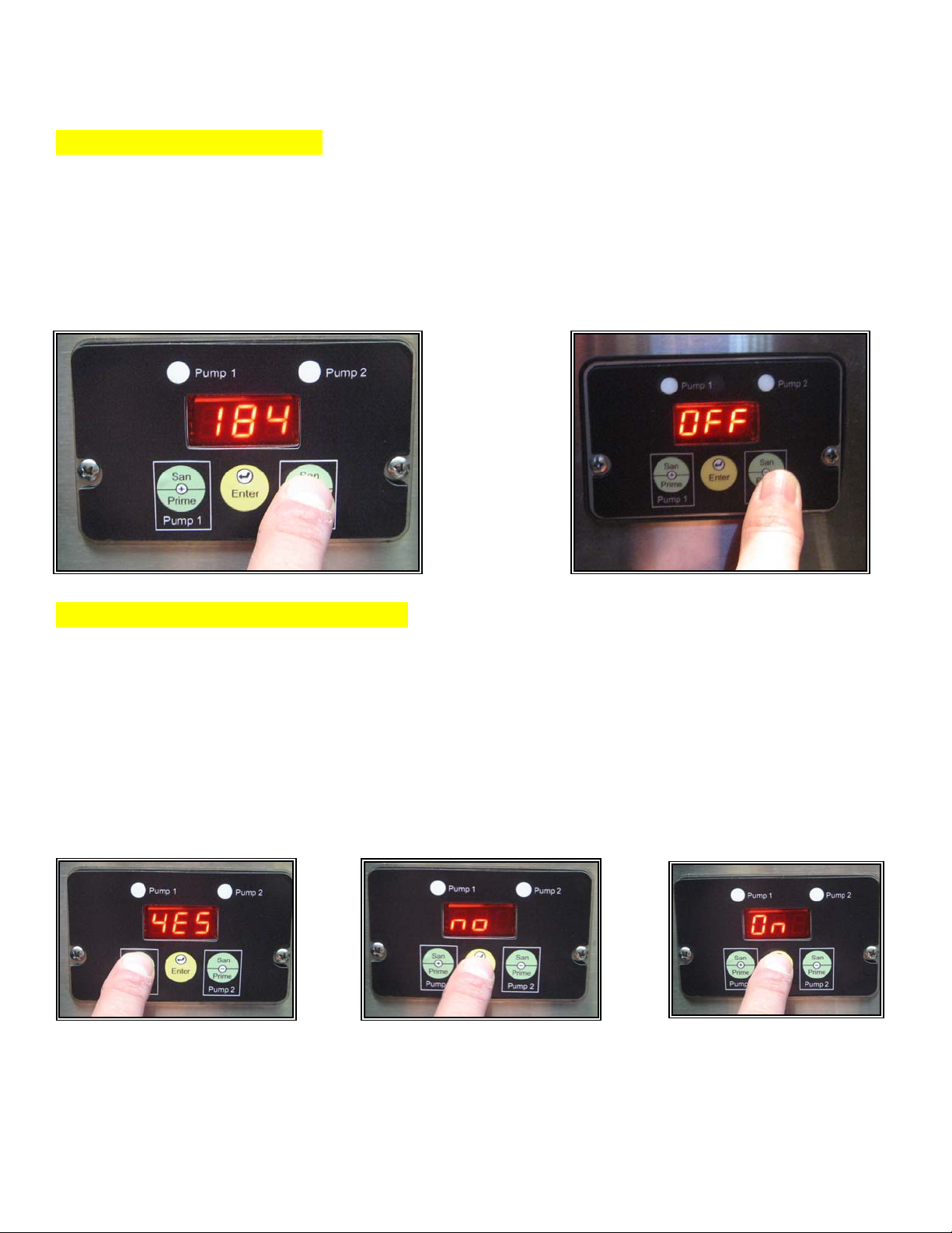
Step 2. Adjust Temperature
The machine features an adjustable temperature range of 100-200F. Use the + or – switch to scroll to
the desired temperature setting. (To turn off the heater press the + or - switch until “OFF” is
displayed.) As shown in figures 3 & 3A.
Press the “Enter” switch to save and proceed to the next programming option. Either the word “YES”
or the word “NO” will appear on the display screen.
Fig. 3
Fig. 3A
Step 3. Enable/Disable BIB Tracking
This machine features the option to track the liquid output of a BIB and then alert the operator when
the BIB is empty. (Display will flash the pump number affected and buzzer will beep if enabled.)
To Enable BIB Tracking, use the + or – switch to scroll until the display reads YES. To disable BIB
Tracking, use the + or – switch to scroll until the display reads NO. As shown in figures 4 & 5. When
you have made your selection, press
“ Enter” to save and proceed to the next programming option. On or Off will appear on the display
screen. As shown in figure 6.
Fig 4 Fig 5
Fig 6
13-May-13 Phone: 1.800.325.7867 Fax: 1.636.925.0029 www.newcocoffee.com
5
Page 6

Step 4. Enable/Disable Alarm
This machine features a buzzer alarm that will sound to notify the operator when one of the following
three things has occurred:
• BIB Tracking has detected an empty BIB (See step 4)
• A machine malfunction has been detected
• The machine has completed a sanitization cycle
This feature offers the option to disable the buzzer alarm.
To enable the alarm, use the + or – switch to scroll until the display reads ON.
To disable the alarm use the + or – switch to scroll until the display reads OFF. See figure 7. When
you have made your selection, press “Enter” to save and proceed to the next programming option.
SEL will appear on the display screen. See figure 8.
Fig. 7 Fig. 8
Step 5. Program Selector Switches
This machine features a 7-selector switch control panel. The center switch on the control panel is
reserved for Hot Water Dispense. The remaining 6 switches can be programmed to deliver a drink
from either of the product BIBs or can be programmed to create a drink by blending product from both
BIBs.
In order to proceed with switch programming, it is first necessary to familiarize you with pump
orientation.
Pump 1 is mounted on the left side of the mixing chamber. (When facing the machine from the front.)
Pump 1 supports the product BIB that is installed directly above it.
Pump 2 is mounted on the right side of the mixing chamber. Pump 2 supports the product BIB that is
installed directly above it.
To program a selector switch to create a drink using the product on the left, enter the pump speed
from Chart A below in to Pump 1 and set the speed of Pump 2 to :00
13-May-13 Phone: 1.800.325.7867 Fax: 1.636.925.0029 www.newcocoffee.com
6
Page 7
Program selection single product:
To program a selector switch to create a drink using the product on the right, enter the pump speed
from Chart A in to Pump 2 and set the speed of Pump 1 to 0:00.
Program selection blend products:
To program a selector switch to create a blend using both products, set the speeds of Pump 1 and Pump 2 using Chart B
as a guideline.
High Flow Rate Ratio Chart (Use this chart if the unit is a high flow unit.) See
page 8 for visual of the nozzle.
Chart A
Chart B
Chart C
Ratio
Pump Speed
Setting
Single
45:1 9 4/4 1/6
40:1 11 5/5 1/8
35:1 13 6/6 1/10
30:1 15 7/7 2/11
25:1 19 8/8 3/13
20:1 - 11/11 -
15:1 - 17/17 14:1 - 18/18 -
Pump Speed
Settings
(Blend 50/50)
Pump Speed
Settings
(Blend 25/75)
Low Flow Rate Chart (Use this chart if the unit is a low flow unit.) See page 8 for
visual of the nozzle.
Ratios
45:1 5 1/1
40:1 6 2/2
35:1 7 2/2
30:1 9 3/3
25:1 11 4/4
20:1 15 6/6
15:1 24 9/9
Chart A Pump Speed
Setting
(Single) (Blend)
Chart B Pump Speed
Settings
13-May-13 Phone: 1.800.325.7867 Fax: 1.636.925.0029 www.newcocoffee.com
7
Page 8
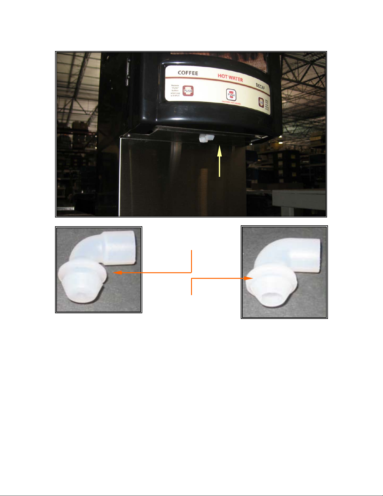
The front nozzle determines the flow rate.
The back nozzle is for hot water use only.
800203, Low Flow Nozzle
(Small Diameter Opening)
800204, High Flow Nozzle
(Large Diameter Opening)
13-May-13 Phone: 1.800.325.7867 Fax: 1.636.925.0029 www.newcocoffee.com
8
Page 9
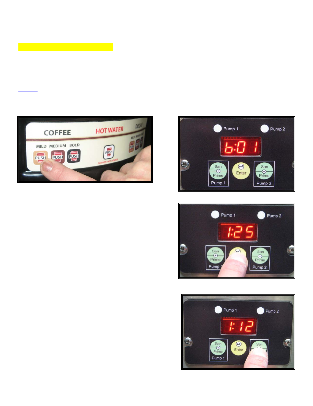
To Program a selector switch:
• On the 7-selector switch control panel, press the switch that you want to program. The display
will change to identify the switch that you have chosen. (b01 thru b06 are the switch
identifiers.) See figures 9 & 10.
NOTE: The optional liquid coffee dispensing unit with a stainless front door uses handles. These act
as buttons for programming. Pulling and holding down the handle acts in the same way as pressing a
button. The center handle is for hot water only and cannot be used for programming.
Fig 10Fig 9
• Press Enter. The number “1” and the current
speed for pump 1 will appear in the display. As
shown in figure 11.
• Using the + or – button to scroll, set Pump 1 speed
for the desired ratio using chart A above as a
guide. (If blending two products, use chart B as a
guide.) As shown in figure 12.
Fig 11
Fig 12
13-May-13 Phone: 1.800.325.7867 Fax: 1.636.925.0029 www.newcocoffee.com
9
Page 10
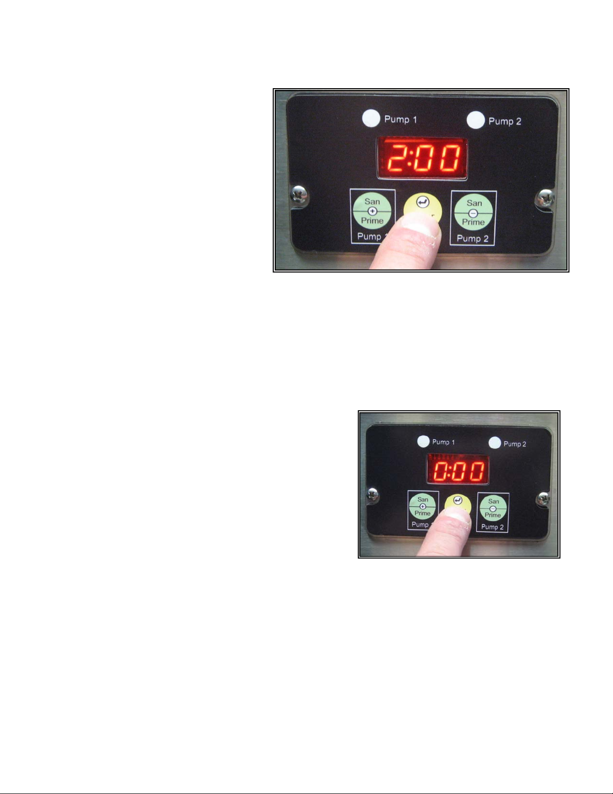
• Press, “Enter” to save and proceed
to set Pump 2. The number “2” and
current pump speed setting for
Pump 2 will appear on the display.
Fig 13
As shown in figure 13.
• Using the + or – button to scroll, set Pump 2 speed for the desired ratio using chart A above as
a guide. (If blending two products, use chart B as a guide.) Refer to figure 12.
• NOTE: (FOR LCD-2 Dual Only) Press “Enter” to save. “HOt” or “CLd” will appear on the
display. This entry chooses whether the selected button will use ambient temperature water
(“CLd”) from the water supply line or hot water (“HOt”) from the tank for dispensing. Use the +
or – button toggle between “HOt” or “CLd.”
• Press “Enter” to save and proceed with the set-up
program. A time value (min: sec) will appear in the
display. If the switch that you are programming has
been set in a portion control mode, the value will
represent the current dispense time for the switch.
If the switch is in a continuous flow (push and hold)
Fig 14
mode, the time value will be 0:00 Shown in figure
14. To set portion control, in this mode, use the +
and – keys to enter the time of dispensing.
• Press “Enter” to save and proceed to the next setup programming option. SEL will appear on the
display.
• Continue with switch programming by repeating steps 1 thru 7.
• When switch programming is completed, continue to press and release the “Enter” button until
the display returns to 3 dashed lines. The machine will be in a normal operating mode.
Fig 14
13-May-13 Phone: 1.800.325.7867 Fax: 1.636.925.0029 www.newcocoffee.com
10
Page 11

Procedure: Setting Portion Control In Normal Run Mode
To program a switch for portioned controls, while in run mode, dispense time must start at “0:00" (See
figure 14) to do this:
1.
Place the desired cup (or carafe) under the dispense head.
2.
Press and hold the “Enter” switch.
Press and hold the selector switch that you want to program.
3.
4.
After two seconds release the “Enter” switch.
5.
When the cup (or carafe) is filled to the desired level, release the selector switch.
6.
The switch is now programmed to automatically fill to that level.
Procedure: Return Switch to Continuous Flow Mode
1. Enter program mode by pressing and holding the “Enter” switch for five seconds.
2. Press and release the “Enter” switch until SEL appears on the display.
3. Press the selector switch that you want to return to continuous flow mode. (The switch
identifier will appear on the display.)
4. Press and release the settings button 3 times. (The selector switch timer will appear on the
display.)
5.
Using the + and – switches, scroll until the selector switch timer reads 0:00
6.
Press and release the “Enter” switch until 3 dashed lines appears on the display.
The switch is now in a continuous flow (push and hold) mode.
Procedure: Disable a Selector Switch
1.
Push and hold the “Enter” switch for 8 seconds to enter a programming mode. The current
temperature setting will appear on the display. (Refer to: Page 3 Programming Mode.)
2.
Press and release the “Enter” switch repeatedly until SEL appears in the display.
3.
Press the selector switch that you have chosen to disable.
4.
Press and release the “Enter” switch. Pump 1 speed will appear in the display.
5. Using the + or – button to scroll, set Pump 1 speed to 0.00
6. Press and release the “Enter” switch. Pump 2 speed will appear in the display.
7. Using the + or – button to scroll, set Pump 2 speed to 0.00
8.
Press and release the “Enter” switch until thee dashed lines appear in the display. The switch
is disabled.
13-May-13 Phone: 1.800.325.7867 Fax: 1.636.925.0029 www.newcocoffee.com
11
Page 12
Section 3
Service Level Programming Functions:
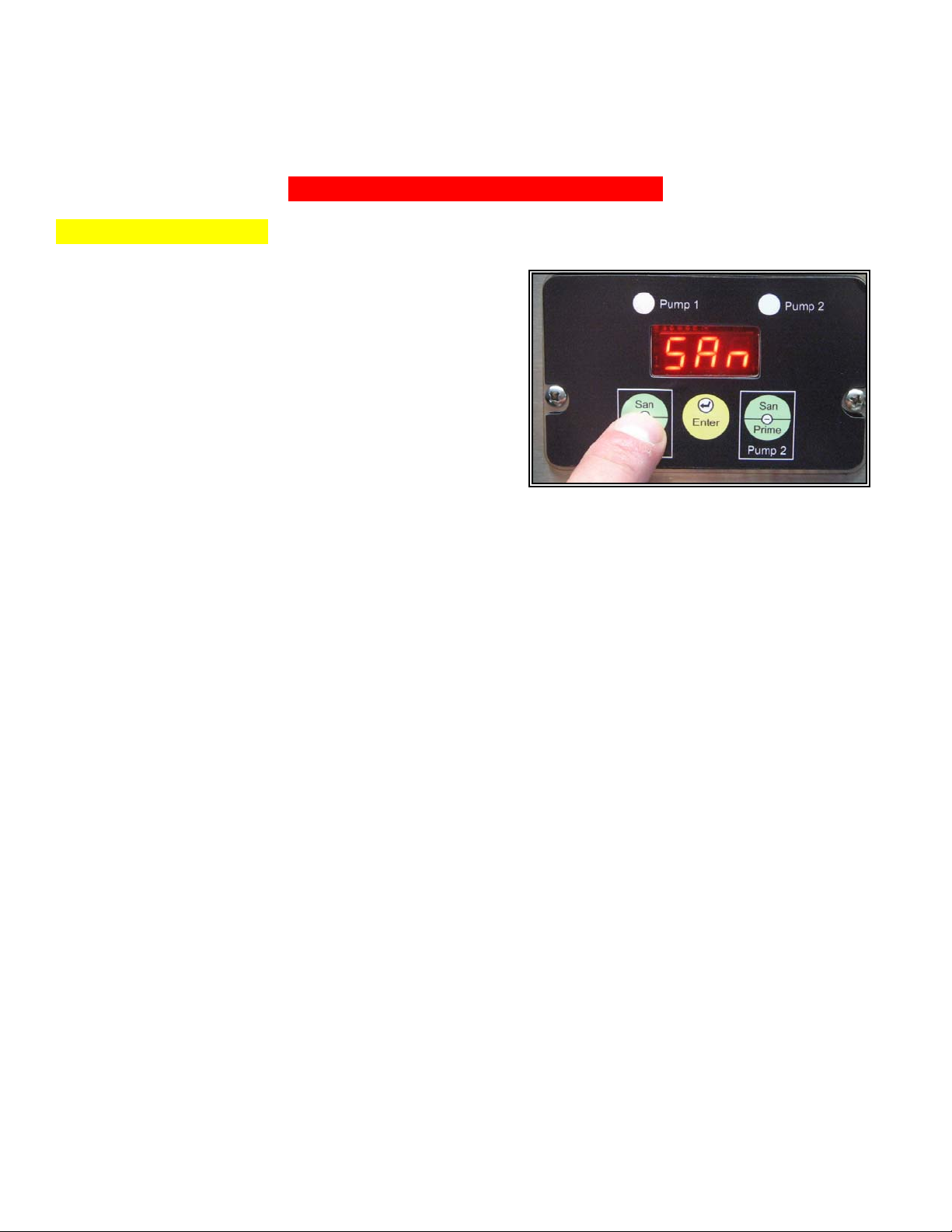
Sanitizing Instructions
Press the + switch to enter sanitize mode. SAN will
appear in the display. (As shown in figure 15)
Remove the product BIBs from the machine and
connect a BIB of sanitizing solution to the PUMP 1 BIB
connector. (The one on the left (as you face the
machine from the front.)
Place an empty decanter or other vessel under the dispense area of the machine.
Press the “Pump 1” (+) switch on the display panel to begin sanitizing.
When sanitizing cycle ends (2.5 minutes total: pump 45 sec., dwell 90 sec., & water 15 sec.), the
buzzer alarm will sound 3 times if enabled during the “Set-Up Programming”. The machine will
automatically advance to “Pump 2”. (Pump 2 will duplicate Pump 1’s process.)
Disconnect the BIB of sanitizing solution from the Pump 1 BIB connector and connect it to the Pump
2 connector.
Press the “Pump 2 (–) switch on the display panel to begin sanitizing.
When sanitizing cycle ends, remove the sanitizing solution and replace the products. The machine
will automatically advance to the Prime Pumps mode.
To Prime: Press and hold the “Pump 1” (+) switch until a steady stream of product flows from the
dispense area into the vessel.
Press the “Enter” switch to advance to Pump 2.
Press and hold the Pump 2 (-) switch until a steady stream of product flows into the vessel.
Press and release the “Enter Switch until 3 dashed lines appear in the display.
Discard the contents of the decanter or vessel.
Fig. 15
13-May-13 Phone: 1.800.325.7867 Fax: 1.636.925.0029 www.newcocoffee.com
12
Page 13
Prime Pump Feature:
This feature allows you to enter directly into a Prime Pump mode without sanitizing.
Press the - switch to enter the Prime Pump mode.
Follow the same Prime Pump procedures from Sanitizing Instructions.
BIB Counter Auto-Reset Feature:
If enabled during the “Set-Up Programming” of the machine a buzzer alarm will sound once per
second to indicate that a product BIB is empty.
Entering into a Prime Pump mode turns off the alarm.
Only reset the pump shown on the display.
BIB tracking is automatically reset when the pump is primed.
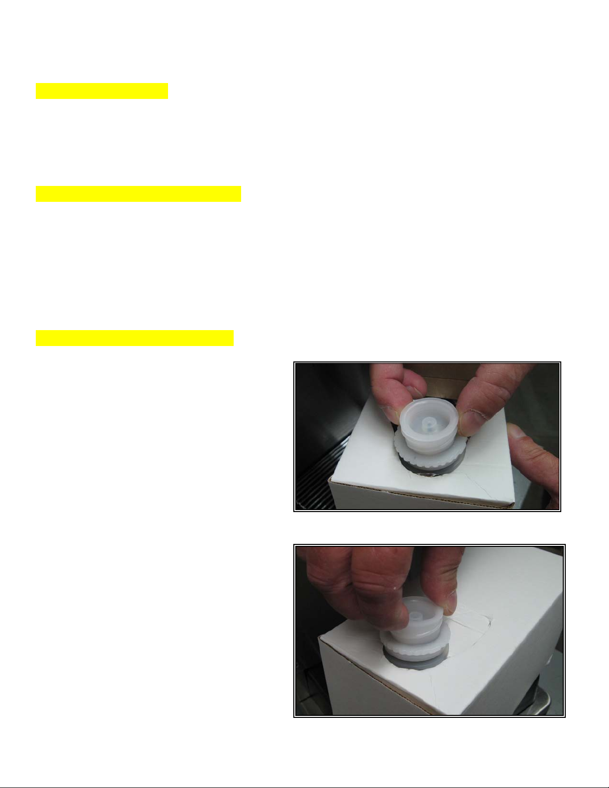
Product Installation Procedures:
• Open the cutout on the product box
and position the BIB fitment into the
slotted area as shown in figure 1.
Remove the plastic insert from the BIB fitment
as shown in figure 2.
Fig. 1
Fig. 2
13-May-13 Phone: 1.800.325.7867 Fax: 1.636.925.0029 www.newcocoffee.com
13
Page 14
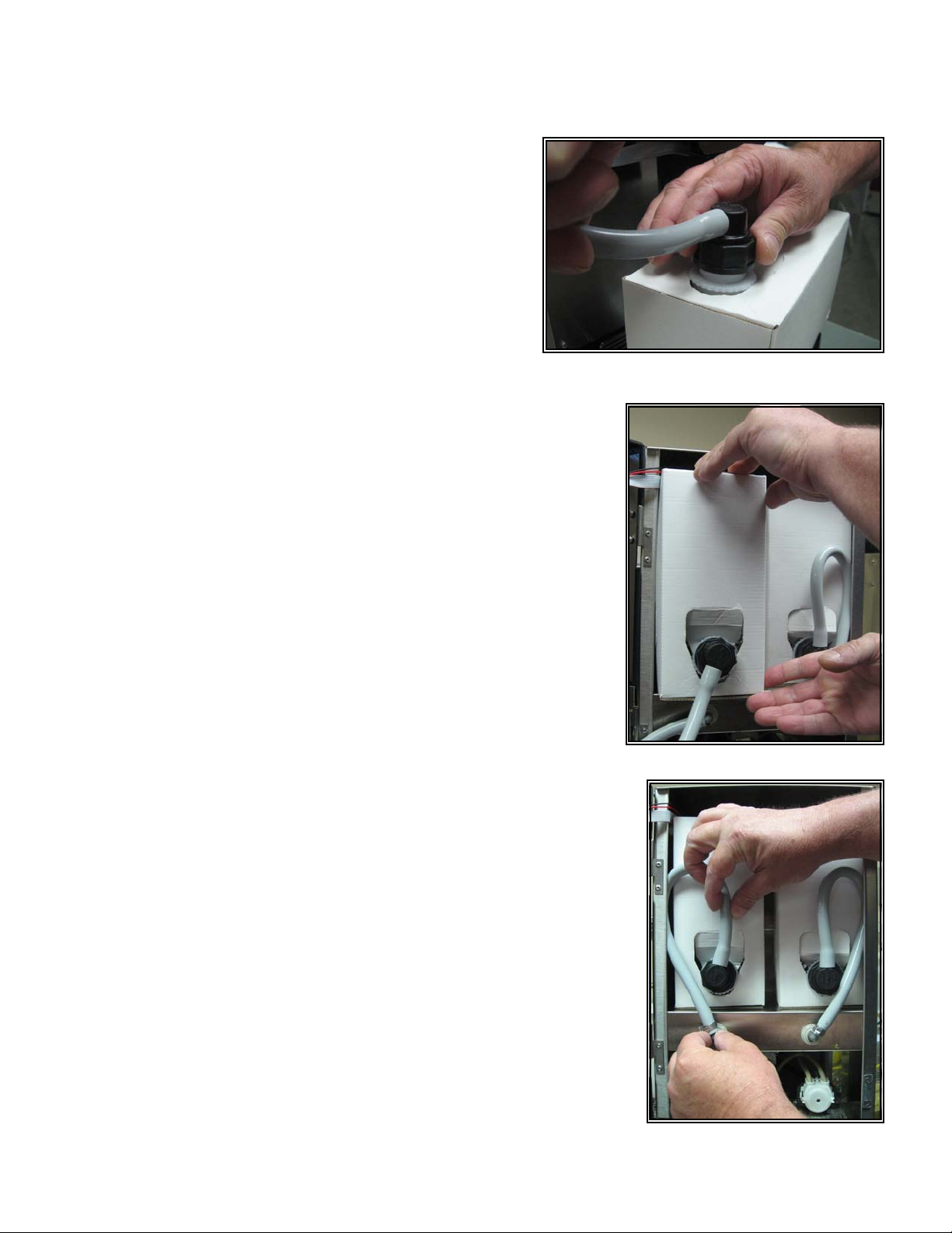
Using finger and thumb only to prevent over-tightening,
thread the BIB connector on to the BIB fitment until
Fig. 3
seated as shown in figure 3.
Place the product in the storage compartment as shown in figure
4.
Position the tubing as shown in figure 5
Fig. 4
Fig. 5
13-May-13 Phone: 1.800.325.7867 Fax: 1.636.925.0029 www.newcocoffee.com
14
Page 15

Cleaning & Sanitizing Instructions:
Remove product from storage area and disconnect BIB connectors as shown in figures 1 & 2.
Fig. 1
Place an empty container in the dispense area of the machine as shown
in figure 3.
Connect the sanitizing solution to the BIB connector for Pump 1 (the
connector on the left as you face the machine from the front) and place
sanitizing BIB on the product shelf as shown in figures 4 & 5
Fig. 4 Fig. 5
Fig. 2
Fig. 3
13-May-13 Phone: 1.800.325.7867 Fax: 1.636.925.0029 www.newcocoffee.com
15
Page 16

Press the Pump 1 button to enter sanitizing mode as
Fig. 6
shown in figure 6.
Press the Pump 1 button again to begin sanitizing. Sanitization cycle will run for
2-1/2 minutes. Buzzer alarm will sound 3 beeps when cycle is complete.
Fig. 7 Fig. 8
Disconnect sanitizing solution from Pump 1 and connect to the BIB connector for PUMP 2 as shown
figures 7 & 8.
Press Pump 2 button to begin sanitizing Pump as shown
in figure 9.
Fig. 9
13-May-13 Phone: 1.800.325.7867 Fax: 1.636.925.0029 www.newcocoffee.com
16
Page 17

When cycle is finished remove sanitizing solution and reinstall
products as shown in figure 10.
Press and hold Pump 1 button until product flows from dispense head
to prime pump 1 as shown in figure 11.
Press enter to proceed to Pump 2 as shown in figure 12.
Press and hold Pump 2 button until product flows from dispense head
to prime Pump 2 as shown in figure 13.
Fig. 10
Fig. 11
Fig. 12
Fig. 13
13-May-13 Phone: 1.800.325.7867 Fax: 1.636.925.0029 www.newcocoffee.com
17
Page 18

Press enter to return to the normal operating mode as
shown in figure 14.
Fig. 14
Flushing Instructions:
Flush the mixing chamber by pressing and holding the “Enter” button for 5 seconds until “FLU”
appears on the display. Release the “Enter” button. Press and hold either the + or – button to flush
the mixing chamber with water. (Refer to: Page 3 Figure No. 2.)
13-May-13 Phone: 1.800.325.7867 Fax: 1.636.925.0029 www.newcocoffee.com
18
Page 19

Error Messages:
Error
Number
tHU/ tHL Thermistor warning –
Er3 Heater Run Error Water did not heat within timeout
Er4 Tank Fill Error Water did not reach probe in
Er5 Comm Error Serial communication error
Er7 Open Motor Circuit - The motor
Description Cause What to Check
Resistance extremely high from
immediately upon detection the
machine will beep twice and
show the warning message for
a minute as well as turn on the
right most upper dot on the
display. This dot will stay on to
signify there is a thermistor out.
Also upon power up the
machine will beep twice and
show the warning message for
a short period of time and turn
on the high dot if the warning
conditions are present
errors (Er7 and Er8) do not
cause a system error and will
not shut down the machine.
Immediately upon detection the
machine will beep twice and
show the error message. Every
time the key is pressed to
activate a dispense motor it
clears the error and allow
another attempt to be made. If
this error occurs the dump
valve still will release water.
upper or lower thermistor will
cause or the resistance extremely
low from upper or lower
thermistor will cause a tHU or tHL
warning for the thermistor that
sees the condition and causes
the control board to switch from
watching the lower to the upper
thermistor. If both the upper and
lower resisters fail then we flag a
thermistor ErC error
period. Timeout period is 240
seconds which is reloaded
whenever the heater is off or the
fill valve is on
timeout period of 6 minutes for
initial fill and 1 minute during
normal operation. The 6 minute fill
time is reloaded if no key is
pressed within 24 hours
to/from non-volatile memory
(EEPROM).
Open motor circuit. Pump 0 or
pump 1.
This warns you that 1
thermistor has failed. Nothing
is required at this time as the
upper thermistor has taken
over but ordering a
replacement thermistor is
advisable
Check element for short and
proper resistance. Replace if
bad.
Check valve function and flow
rate. Replace valve or
increase flow rate. Check
probes for excess scale.
Hold down the enter key to
enter Machine Set up mode
pressing the enter key to
cycle through all options then
exit mode. This resets all the
defaults. If the error still
occurs then replace main
board.
Retry pump if the error still
occurs then check
harness/motor continuity.
Replace if defective.
13-May-13 Phone: 1.800.325.7867 Fax: 1.636.925.0029 www.newcocoffee.com
19
Page 20

Error Messages Cont’d:
Er8 Bad (Open) Motor Driver - The
motor errors (Er7 and Er8) do
not cause a system error and
will not shut down the machine.
Immediately upon detection the
machine will beep twice and
show the error message. Every
time the key is pressed to
activate a dispense motor it
clears the error and allow
another attempt to be made. If
this error occurs the dump
valve still will release water.
Erb Dry Firing Tank – the tank is
empty but the heater is on.
ErC Thermistor Error Resistance extremely high from
Bad/open motor driver. Pump 0 or
pump 1.
The control board has either seen
a rise in temperature of 1 degree
a second, for 5 seconds or has
seen the temperature rise to
215°F or above
upper or lower thermistor will
cause or the resistance extremely
low from upper or lower
thermistor will cause a tHU or tHL
warning for the thermistor that
sees the condition and causes
the control board to switch from
watching the lower to the upper
thermistor. If both the upper and
lower resisters fail then we flag a
thermistor error
Retry pump if the error still
occurs then replace main
board.
The unit has been in the
intent to brew timeout for an
extended period of time,
allowing the tank to evaporate
to the point where there is
little water in the tank
Check/replace thermistor.
13-May-13 Phone: 1.800.325.7867 Fax: 1.636.925.0029 www.newcocoffee.com
20
Page 21

Dimensions & Electrical Specifications:
LCD-2 LIQUID COFFEE DISPENSER
**Electrical Specs**
PN: 120309, LCD-2
120V 1750W
15 Amps
PN: 120354, LCD-2
120V/240V 3500W
15 Amps
13-May-13 Phone: 1.800.325.7867 Fax: 1.636.925.0029 www.newcocoffee.com
21
Page 22

Electrical Schematics:
13-May-13 Phone: 1.800.325.7867 Fax: 1.636.925.0029 www.newcocoffee.com
22
Page 23

Electrical Schematics:
13-May-13 Phone: 1.800.325.7867 Fax: 1.636.925.0029 www.newcocoffee.com
23
Page 24

Electrical Schematics:
13-May-13 Phone: 1.800.325.7867 Fax: 1.636.925.0029 www.newcocoffee.com
24
Page 25

Spare Parts:
ITEM # IMAGE DESCRIPTION UM
Base Assembly & Door Assembly
120313
100054
100061
100104
105048
Base Assembly, LCD-2
Washer, #8 External Lock SS 1 EA.
1 EA.
Nut, 8-32 Hex SS 1 EA.
Washer, 3/8” External Lock Zinc 1 EA.
Screw, 8-32 x 3/8” With Washer PPHMS SS 1 EA.
111322
Trim, GX Radius Base 3/4" 1 EA.
111377
Foot, Appliance 3/8-16 x 1” 1 EA.
111667
Nut, 3/8-16 Jam ZPS 1 EA.
13-May-13 Phone: 1.800.325.7867 Fax: 1.636.925.0029 www.newcocoffee.com
25
Page 26

Spare Parts:
ITEM # IMAGE DESCRIPTION UM
Base Assembly & Door Assembly - Continued
120334
100055
100191
100212
100243
Door Assembly, LCD-2 Hot
1 EA.
Screw, 4-40 x 3/8” PPHMS SS 1 EA.
Nut, 6-32 Hex SS 1 EA.
Washer, #6 External Lock SS 1 EA.
Nut, 4-40 Hex SS 1 EA.
102065
Magnet, Door 1 EA.
102333
Screw, 6-32 x 3/8” Combo Head Self Tapping 1 EA.
105043
Screw, 6-32 x 3/8” With Washer PPHMS SS 1 EA.
13-May-13 Phone: 1.800.325.7867 Fax: 1.636.925.0029 www.newcocoffee.com
26
Page 27

Spare Parts:
ITEM # IMAGE DESCRIPTION UM
Base Assembly & Door Assembly - Continued
110766
120335
120336
120350
120351
Washer, #4 Internal Lock 1 EA.
Door, Vacuformed Plastic LCD-2 1 EA.
Panel, Inner Door LCD-2 1 EA.
Membrane Switch, 7 Button LCD 1 EA.
Label, Switch: Coffee – Hot Water – Decaf LCD 1 EA.
120352
Label, Hot Coffee Backlit LCD 1 EA.
120353
Clear Panel, Label LCD 1 EA.
120501
Label, Cleaning Instructions 1 EA.
13-May-13 Phone: 1.800.325.7867 Fax: 1.636.925.0029 www.newcocoffee.com
27
Page 28

Spare Parts:
ITEM # IMAGE DESCRIPTION UM
Base Assembly & Door Assembly - Continued
121403
120421
781259
511050
Display Board Assembly, LCD-2 1 EA.
Light Assembly, LED Strip 1 EA.
Female, Hinge 1 EA.
Bushing, Snap Split 3/4" 1 EA.
13-May-13 Phone: 1.800.325.7867 Fax: 1.636.925.0029 www.newcocoffee.com
28
Page 29

Spare Parts:
ITEM # IMAGE
DESCRIPTION
UM
Tube Assemblies, BIB & Others
120422
120383
107117
120683
120864
Tube Assembly, BIB 12.00”
Silicone Tubing, Grey 1/4 x 1/2 x 12.00” [111240] 1 EA.
Connector, Scholle 1910L 1 EA.
Clamp, SNP6-10C2 Black [Small] 1 EA.
1 EA.
Clamp, SNP8-10C2 Black [Large] 1 EA.
205189
Elbow, 1/4 x 1/4 Trimmed 1 EA.
120387
Silicone Tubing, 1/8” x 1/4" x 16.00” [773186] 1 EA.
120680
Silicone Tubing, 1/4” x 1/2" x 13.00” [781871] 1 EA.
13-May-13 Phone: 1.800.325.7867 Fax: 1.636.925.0029 www.newcocoffee.com
29
Page 30

Spare Parts:
ITEM # IMAGE
Tube Assemblies, BIB & Others - Continued
DESCRIPTION
UM
120681
121315
701038
701702
767345
Silicone Tubing, 1/8” x 1/4" x 12.00” [773186] 1 EA.
Tubing, SS .312 x .020 x 1.00” [100966] 1 EA.
Silicone Tubing, 3/8” x 5/8" x 4 3/4” [152213] 1 EA.
Silicone Tubing, 3/8” x 5/8" x 32.00” [152213] 1 EA.
Teflon Tubing, 3/16” x 1/4" x 12.00” [100445] 1 EA.
781496
Silicone Tubing, 3/8” x 5/8" x 3.00” [152213] 1 EA.
13-May-13 Phone: 1.800.325.7867 Fax: 1.636.925.0029 www.newcocoffee.com
30
Page 31

Spare Parts:
ITEM # IMAGE DESCRIPTION UM
Tank Assembly
120553
100030
100149
100166
100170
Tank Assembly, 1750W LCD-2
Gasket, Brass .566 ID 1 EA.
Elbow, Male 1/4C x 1/8NPT 1 EA.
Sleeve, 3/8” Compression Brass 1 EA.
Nut, 3/8” Compression Brass 1 EA.
1 EA.
100431
Nut, 9/16-24 x 11/16H Brass 1 EA.
101720
Connector, Female 3/8C x 1/8NPT Brass 1 EA.
102333
Screw, 6-32 x 3/8” Combo Head Self Tapping 1 EA.
13-May-13 Phone: 1.800.325.7867 Fax: 1.636.925.0029 www.newcocoffee.com
31
Page 32

Spare Parts:
ITEM # IMAGE DESCRIPTION UM
Tank Assembly - Continued
102835
110944
110946
119879
119882
Bulkhead, Faucet Outlet 1 EA.
Sleeve, 1/4" Self Aligning Compression Brass 1 EA.
Nut, 1/4" Self Aligning Compression Brass 1 EA.
Nut, Faucet 3/8-18 Chrome Plated 1 EA.
Gasket, Tank 1 EA.
120332
Lid Assembly, 1750W LCD-2
1 EA.
100190
Nut, Jam 1/2-20 Jam Brass 1 EA.
100269
Bracket, Hi Limit Thermostat 1 EA.
13-May-13 Phone: 1.800.325.7867 Fax: 1.636.925.0029 www.newcocoffee.com
32
Page 33

Spare Parts:
ITEM # IMAGE DESCRIPTION UM
Tank Assembly - Continued
100409
500396
111593
120333
151677
Gasket, .520 ID Brass 1 EA.
Probe Assembly, 1.537” With Bushing 1 EA.
Hi Limit Thermostat, Vertical Tabs 221F 25A 1 EA.
Lid Only, LCD-2 Tank 1 EA.
Temperature Probe, Dual 7.312” 1 EA.
152207
Plug, Tank Cover Silicone Natural 1 EA.
202025-10
Element Tank, 1750W 120V 1 EA.
500038
Silicone Grommet, No Slit .060 1 EA.
13-May-13 Phone: 1.800.325.7867 Fax: 1.636.925.0029 www.newcocoffee.com
33
Page 34

Spare Parts:
ITEM # IMAGE DESCRIPTION UM
Tank Assembly - Continued
800297
120388
120549
202044
781468
Tube, Vent 6.5” 1 EA.
Fill Tube, LCD-2 1 EA.
Tank Only, LCD-2 1 EA.
Insert, Tubing 3/16” 1 EA.
Fitting, Tea Modified [800236] 1 EA.
800244
121446
Nylon Gasket, .671 x .937 x .062 1 EA.
Solenoid Valve, Dump 12V INVNSYS GS56
[Hot Water Faucet]
1 EA.
120386
Valve, Dump With Vent 120V LCD 1 EA.
13-May-13 Phone: 1.800.325.7867 Fax: 1.636.925.0029 www.newcocoffee.com
34
Page 35

Spare Parts:
ITEM # IMAGE DESCRIPTION UM
Panel Assembly
120658
120545-BPC
100191
100212
100409
103277
Front Panel Assembly, LCD-2 [SS Model]
Front Panel Assembly, LCD-2 [BPC Model]
1 EA.
Nut, 6-32 Hex SS 1 EA.
Washer, #6 External Lock SS 1 EA.
Gasket, .520 ID Brass 1 EA.
Retainer, Tubing 1 EA.
104155
104204
Pump Head Assembly, LCD-2 1 EA.
Tubing, Neoprene .117 x .197 x 12.25” 1 EA.
107151
Tube/Hose, Barb 1/4 x 3/16 1 EA.
13-May-13 Phone: 1.800.325.7867 Fax: 1.636.925.0029 www.newcocoffee.com
35
Page 36

Spare Parts:
ITEM # IMAGE DESCRIPTION UM
Panel Assembly - Continued
120391
120428
500024
104161
105043
Tube/Hose, 1/4 x 3/16 Modified 1 EA.
Mounting Bracket, Pump LCD-2 1 EA.
Screw, 2.6 mm x 5.0 mm FHMS SS 1 EA.
Chamber, Mix Double Stem
1 EA.
Screw With Washer, 6-32 x 3/8” PPHMS SS 1 EA.
111634
111635
Hose Clamp, .459ID 1 EA.
Hose Clamp, .574ID 1 EA.
120487
Bracket, Mix Chamber Retainer Elbow 1 EA.
13-May-13 Phone: 1.800.325.7867 Fax: 1.636.925.0029 www.newcocoffee.com
36
Page 37

Spare Parts:
ITEM # IMAGE DESCRIPTION UM
Panel Assembly – Continued
205083
411039
700021
800203
800204
Bulkhead Union, 1/4 Tube 1 EA.
Hose Clamp, .510ID 1 EA.
Knurled Nut, 8-32 Brass 1 EA.
Elbow, Spray BF [Small Diameter Opening] 1 EA.
Elbow, Outlet BF [Large Diameter Opening] 1 EA.
120493 NA Kit, Pump Head Assembly LCD-2 1 EA.
120509
120513
13-May-13 Phone: 1.800.325.7867 Fax: 1.636.925.0029 www.newcocoffee.com
Connector – Tubing Cleaning Kit [BevClean] 1 EA.
BevClean, 1 Gallon 1 EA.
37
Page 38

Spare Parts:
ITEM # IMAGE DESCRIPTION UM
Valve Assembly
781782
100161
100177
101377
102383
Valve Assembly, Mini Capp
Tube Assembly, Copper 1/4" x .030 x .88 1 EA.
Elbow, Male 1/4F x 1/8P 1 EA.
Fitting, Solenoid 1/8P 1 EA.
Valve, Solenoid TP 3/4 x 1/4 1 EA.
1 EA.
202105
100291
110114
Flow Assembly, Flare To Flare .50 GPM
Flow Washer, .50 GPM Light Blue 1 EA.
Flow Control Screen, PDS 1 EA.
1 EA.
13-May-13 Phone: 1.800.325.7867 Fax: 1.636.925.0029 www.newcocoffee.com
38
Page 39

Spare Parts:
ITEM # IMAGE DESCRIPTION UM
Valve Assembly – Continued
202103
790019
121431
121436
Strainer/Flow Control Body With Caps, Only
Nylon Gasket, Flow Control 1 EA.
1 EA.
Drip Tray Assembly
Molded Cup Guide, LCD-2 1 EA.
Label Set, “Place Cup Here”
“Caution Hot Liquids”
1 EA.
773214
773213
Drip Tray Grid, Only 1 EA.
Drip Tray Only, With Indicator 1 EA.
13-May-13 Phone: 1.800.325.7867 Fax: 1.636.925.0029 www.newcocoffee.com
39
Page 40

Spare Parts:
ITEM # IMAGE DESCRIPTION UM
Miscellaneous Components
100054
100061
100408
101035
104015
Lock Washer, #8 SS
1 EA.
Nut, 8-32 Hex SS 1 EA.
Plug, Barbed Tubing PP 1 EA.
Grommet, Strain Relief 14/3 1 EA.
Bezel, Adaptor Black Plastic 1 EA.
104137
104151
105048
Washer, Star Lock .690 ID 1 EA.
Check Valve, Duck .301 x 0.656 1 EA.
Screw, 8-32 x 3/8” Washer PPHMS SS 1 EA.
13-May-13 Phone: 1.800.325.7867 Fax: 1.636.925.0029 www.newcocoffee.com
40
Page 41

Spare Parts:
ITEM # IMAGE DESCRIPTION UM
Miscellaneous Components - Continued
105115
110626
110958
111634
111635
Transformer, 120VP 24VCT 40VA 2 EA.
On – Off Switch, Power 1 EA.
Relay, 12V DC 1 EA.
Hose Clamp, .459ID 1 EA.
Hose Clamp, .574ID 1 EA.
111668
120436
781843
Acorn Nut Locking 6-32, SS 1 EA.
Spring Retainer Clip, Mix Chamber 1 EA.
Power Cord, 14/3 With Shrink 1 EA.
13-May-13 Phone: 1.800.325.7867 Fax: 1.636.925.0029 www.newcocoffee.com
41
Page 42

Spare Parts:
ITEM # IMAGE DESCRIPTION UM
Miscellaneous Components - Continued
120567
201222
511027
700021
701646
Control Board Assembly, LCD-2 1 EA.
Frame, Switch 1 EA.
Screw, 8-32 x 3/8” SPHMS SS 1 EA.
Nut, Knurled 8-32 Brass 1 EA.
Hose Clamp, Plastic 1 EA.
781258
781697
Hinge, Male Cappuccino 1 EA.
Clamp, Adhesive 1 EA.
500354
Probe, 1.537” Passivated
13-May-13 Phone: 1.800.325.7867 Fax: 1.636.925.0029 www.newcocoffee.com
42
Page 43

Spare Parts:
ITEM # IMAGE DESCRIPTION UM
Miscellaneous Components - Continued
500350
500351
500382
781539
103600
NA
Grommet, Probe Bushing 5/16” 1 EA.
Bushing, Probe Insulator 1 EA.
Probe Assembly Kit, 1.537”
[Consists of: 1 ea. 500350, Probe Assy., & Instruction]
Screw, 8-32 X 1 3/8” PPHMS SS
[Used on Fan Assembly]
Fan Assembly 1 EA.
1 EA.
1 EA.
123092
100669
131133
Fan Harness, With Rectifier & Capacitor 1 EA.
Bridge Rectifier 1 EA.
Grommet, Solenoid Valve [Dump] 1 EA.
13-May-13 Phone: 1.800.325.7867 Fax: 1.636.925.0029 www.newcocoffee.com
43
Page 44

Spare Parts:
ITEM # IMAGE DESCRIPTION UM
Door Assembly: Metal Door Model
120546-BPC
100055
100191
100212
100243
Door Assembly, LCD-2 Hot Metal Door
1 EA.
Screw, 4-40 x 3/8” PPHMS SS 1 EA.
Nut, 6-32 Hex SS 1 EA.
Washer, #6 External Lock SS 1 EA.
Nut, 4-40 Hex SS 1 EA.
102065
Magnet, Door 1 EA.
102333
Screw, 6-32 x 3/8” Combo Head Self Tapping 1 EA.
105043
Screw, 6-32 x 3/8” With Washer PPHMS SS 1 EA.
13-May-13 Phone: 1.800.325.7867 Fax: 1.636.925.0029 www.newcocoffee.com
44
Page 45

Spare Parts:
ITEM # IMAGE DESCRIPTION UM
Door Assembly: Metal Door Model - Continued
110766
121403
120448
120452
120453
Washer, #4 Internal Lock 1 EA.
Display Board Assembly, LCD-2 1 EA.
Spring, Nudger Faucet 1 EA.
Cam Lock 50 Series 1 EA.
Striker Plate, Lock 50 series 1 EA.
120480
Label, LCD-2 Metal Door R/HW/D 3 Faucet 1 EA.
120481
Bracket Assembly, Micro Switch [Metal Door] 1 EA.
120558
Lock, Cam Sealed Black 1 EA.
13-May-13 Phone: 1.800.325.7867 Fax: 1.636.925.0029 www.newcocoffee.com
45
Page 46

Spare Parts:
ITEM # IMAGE DESCRIPTION UM
Door Assembly: Metal Door Model - Continued
120568
120569
120570
120571
120573
Handle, Decaf LCD [Metal Door] 1 EA.
Handle, Hot Water LCD [Metal Door] 1 EA.
Handle, Coffee LCD [Metal Door] 1 EA.
Pin, Handle Faucet LCD 1 EA.
Stem, Faucet LCD 1 EA.
120594
Bonnet With Holes 1 EA.
511050
Bushing, Snap Split 3/4" 1 EA.
13-May-13 Phone: 1.800.325.7867 Fax: 1.636.925.0029 www.newcocoffee.com
46
Page 47

Additional LCD-2 Models PN
LCD-2, 240V, Hot 120354
LCD-2, 120V, Hot With Fan 120532
LCD-2, 240V, Hot, Metal Door 120502
LCD-2, 240V, Hot, Metal Door With Fan 120559
LCD-2, 240V, Hot/Ambient (Dual Temp.) 120449
LCD-2, 120V, Hot/Ambient With Fan (Dual Temp.) 120520
13-May-13 Phone: 1.800.325.7867 Fax: 1.636.925.0029 www.newcocoffee.com
47
Page 48

13-May-13 Phone: 1.800.325.7867 Fax: 1.636.925.0029 www.newcocoffee.com
48
 Loading...