

Page 1

INSTALLATION
INSTALLATION
PROCEDURE
PROCEDURE
September 2006
Page 2
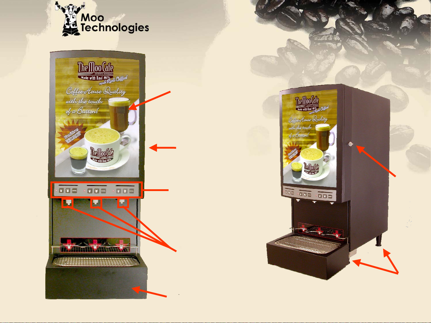
Translucent
Door Graphic
Cabinet
Door
Programmable
Dispense Buttons
Unit Overview
Unit Overview
Door
Latch
Dispensing
Nozzles
Drip Tray and
Drain Assembly
Legs
(4)
Page 3
BIB
Installation
Instructions
Programming
Instructions
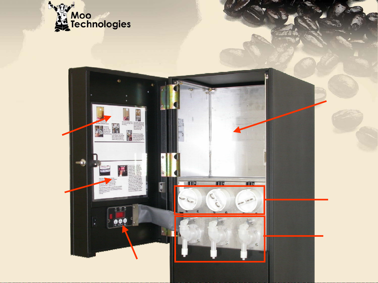
Unit Overview
Unit Overview
BIB
Cabinet
Pump
Display
Board
Assemblies
Whipper
Assemblies
Page 4
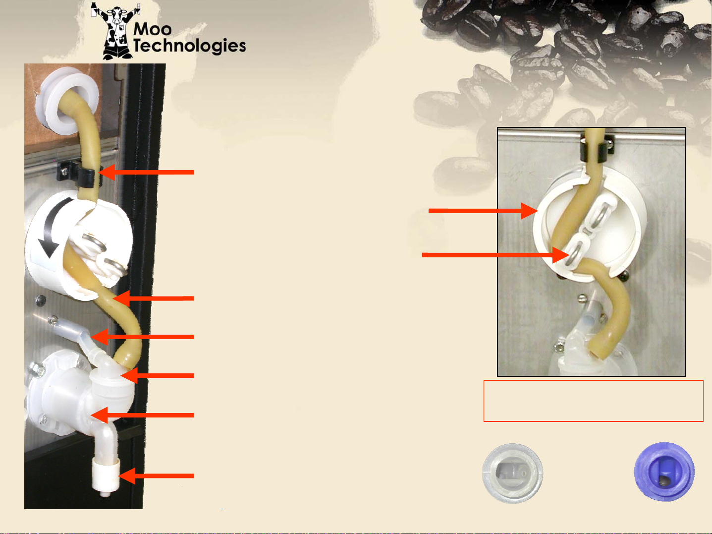
Unit Overview
Unit Overview
Plastic Tubing Holder
Pump Housing
Pump Rotor
BIB Product Tube
Water Supply Tube
Whipper Dosing Head
Whipper Chamber
Whipper Restrictor
Note: Pump Rotor should only
be rotated counter-clockwise
Dosing
Heads
Moo
Expresso
Page 5
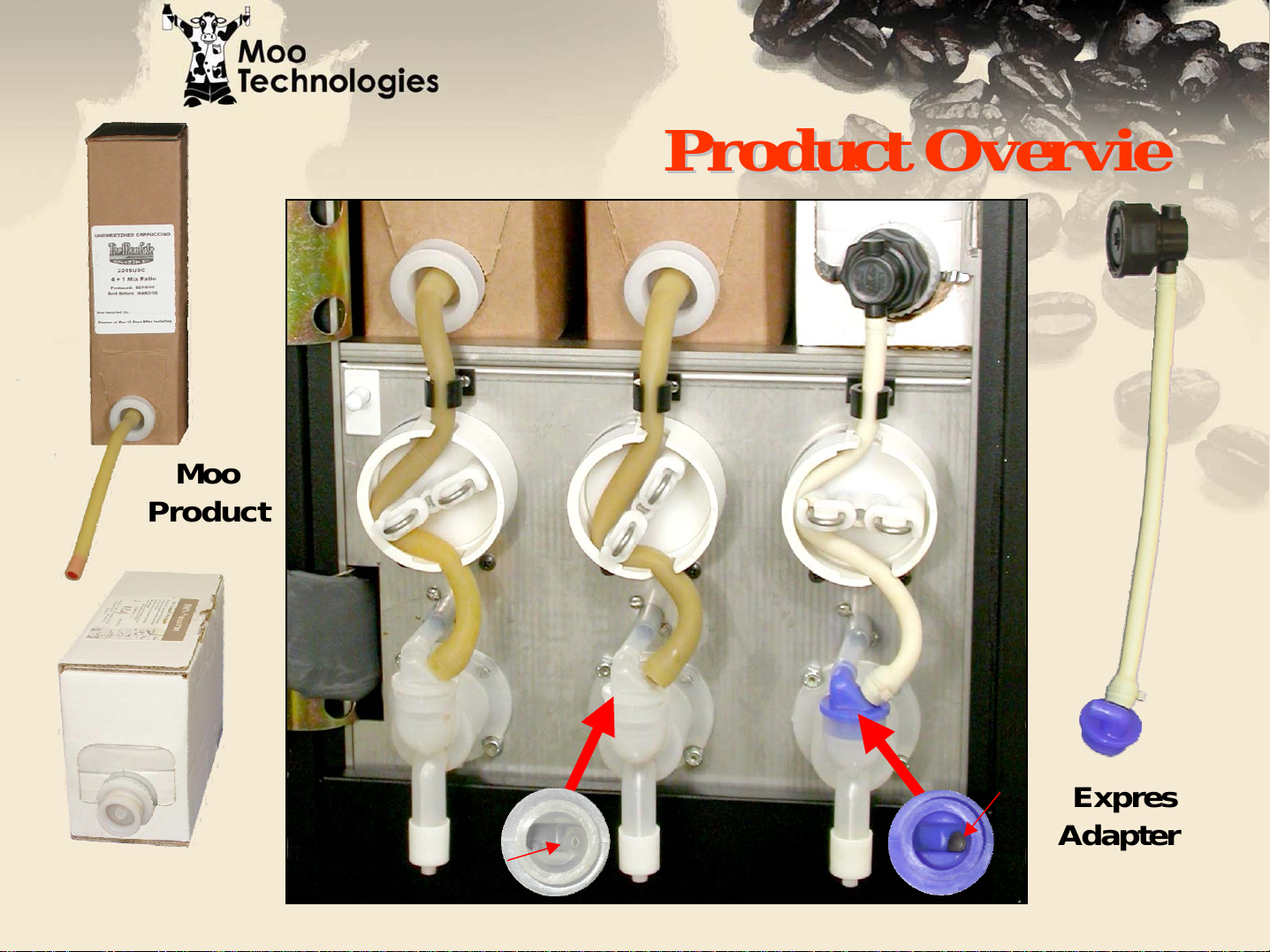
Moo
Product
Product Overview
Product Overview
Expresso
Product
Check
Valve
No
Check
Valve
Moo Dosing Head Expresso Dosing Head
Expresso
Adapter Kit
Page 6

Shipping Carton Contents
Shipping Carton Contents
• MCM-Combo Unit
• Drip Tray Assembly (drain hose included)
• Water Filter (with shut-off & mounting hardware)
• Four Inch Plastic Legs (4)
• Fluorescent Tubes (2)
• Translucent Door Graphic
Page 7
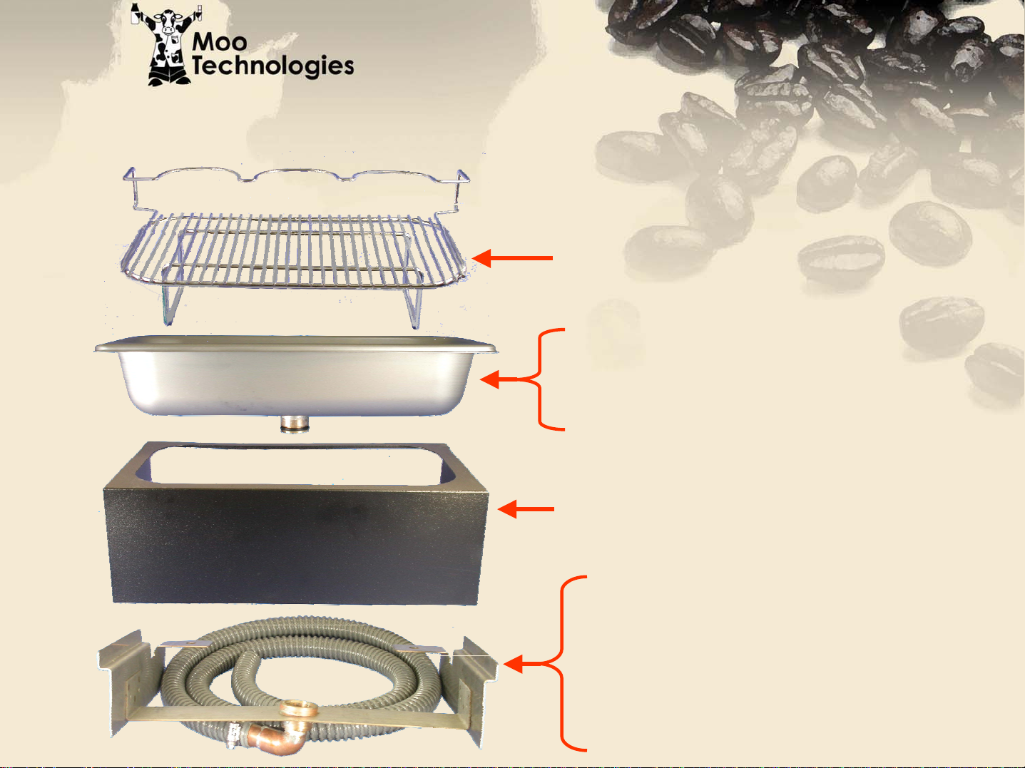
Drip Tray Assembly
Drip Tray Assembly
103426 Cup Rest
103415 Drain Pan
103425 Drain Pan Fitting
02-0158 O-Ring
103420-BPC Drip Tray Housing
103417 Drain Support Bracket
103424 Drain Receptacle
103455 Drain Hose
103452 Hose Clamp
Page 8
511027
100054
100754
103382
103457
111622
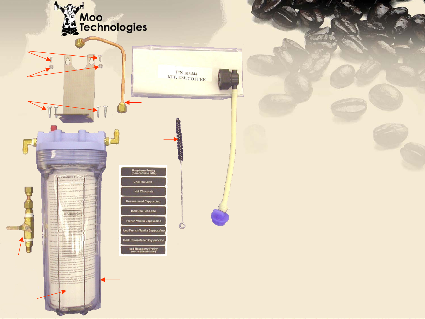
Water Filter
Water Filter
Accessories Bag
Accessories Bag
Product Labels
Nozzle Brush
Shut-off Assembly
Water Filter
Water Filter Bracket
Filter to Unit Water Line
103485
107018
Bracket (Unit) Mounting Screws (2)
100626
Bracket (Filter) Mounting Screws (4)
107038
Espresso Product Packing Adapter
Page 9
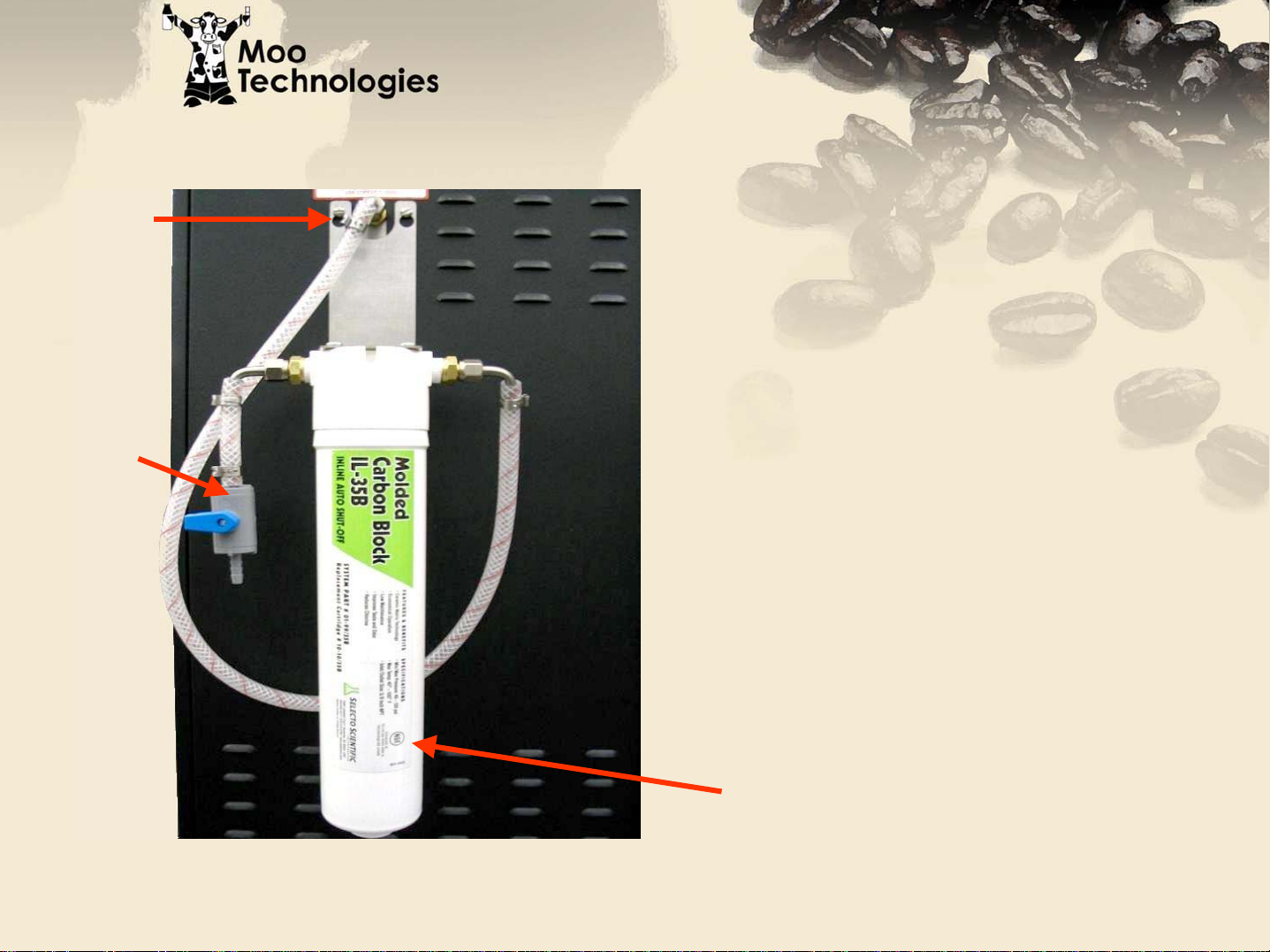
Bracket
New Water
New Water
Filter Assembly
Filter Assembly
New units will be shipped with
an upgraded water filter
Shut-off
assembly. The installation will
be exactly the same as the
previous filter assembly,
however some of the parts
(shutoff, filter, & bracket) may
look slightly different.
Filter cartridge
Page 10

Plastic Legs, Fluorescent Tubes and
Plastic Legs, Fluorescent Tubes and
Translucent Door Graphic
103377
100542
102062
Page 11
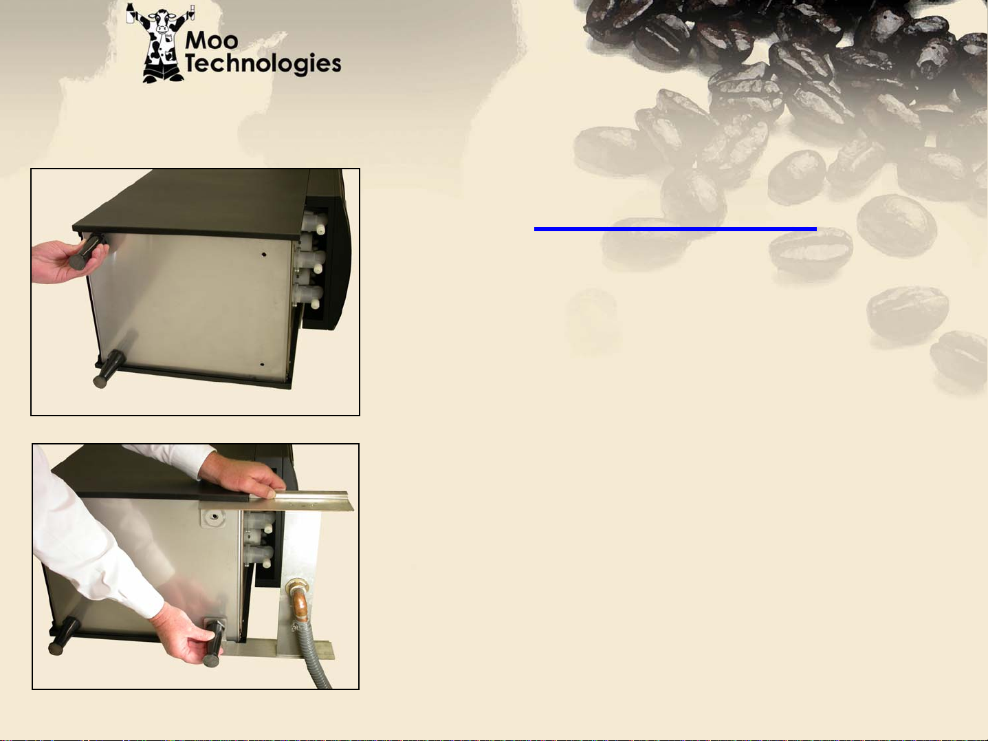
Machine Setup
Machine Setup
1. Install two rear unit legs.
2. Align Drain Support Bracket holes
Leg Installation
with those in bottom front of unit and
install front legs.
Page 12
Machine Setup
Machine Setup
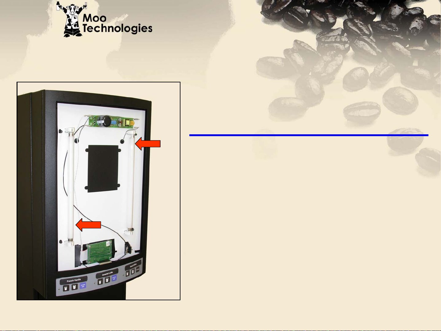
Fluorescent Tube Installation
Install two (2) fluorescent tubes in
door face and rotate ¼ turn to lock in
holder.
Page 13
Machine Setup
Machine Setup
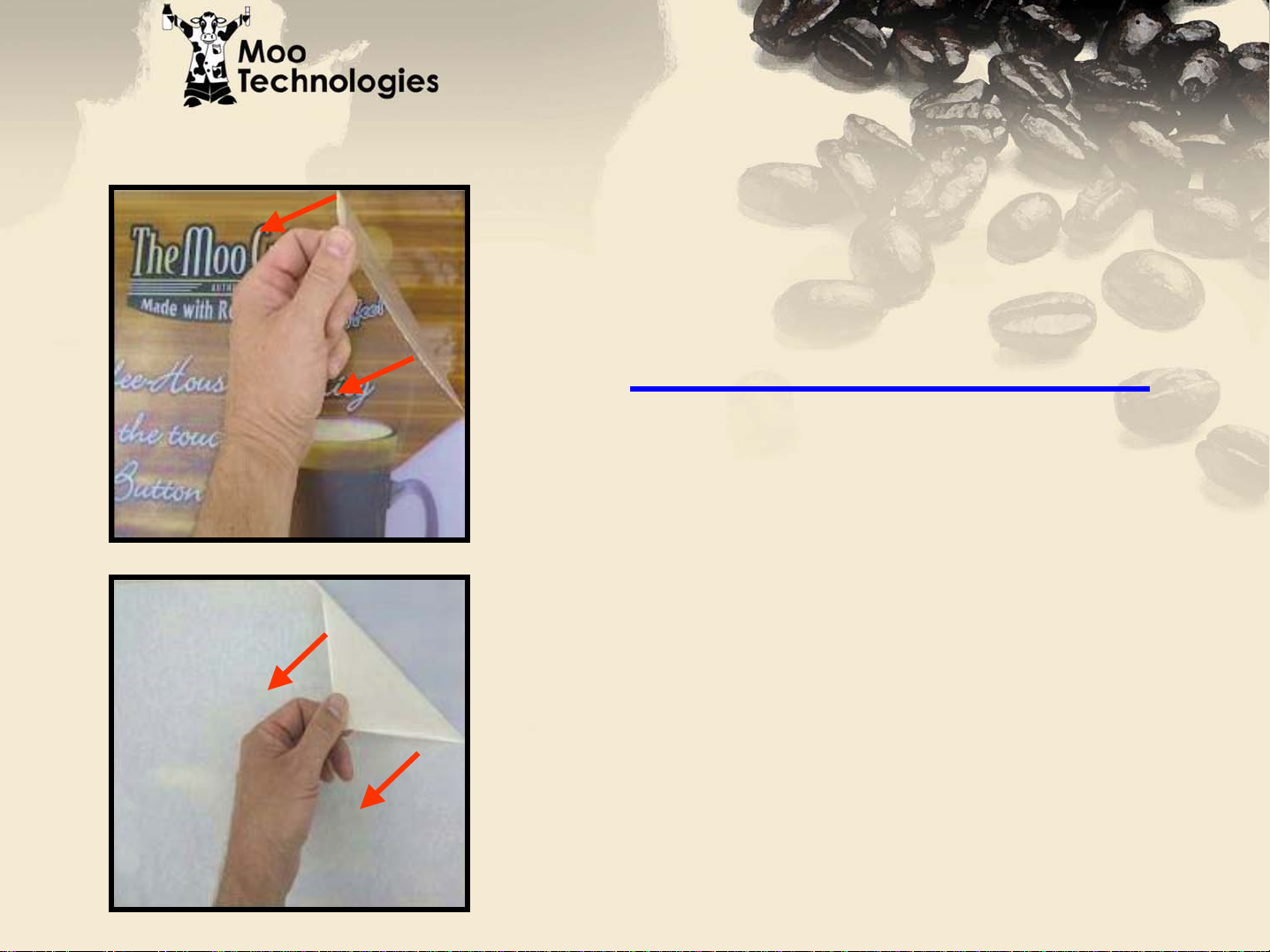
Preparing the Graphic
Both the translucent graphic and
the clear plastic cover shield are
shipped with a protective film.
Translucent Graphic
Clear Plastic Cover
Start at a corner, and carefully pull
the protective film diagonally to
remove.
Page 14
Machine Setup
Machine Setup
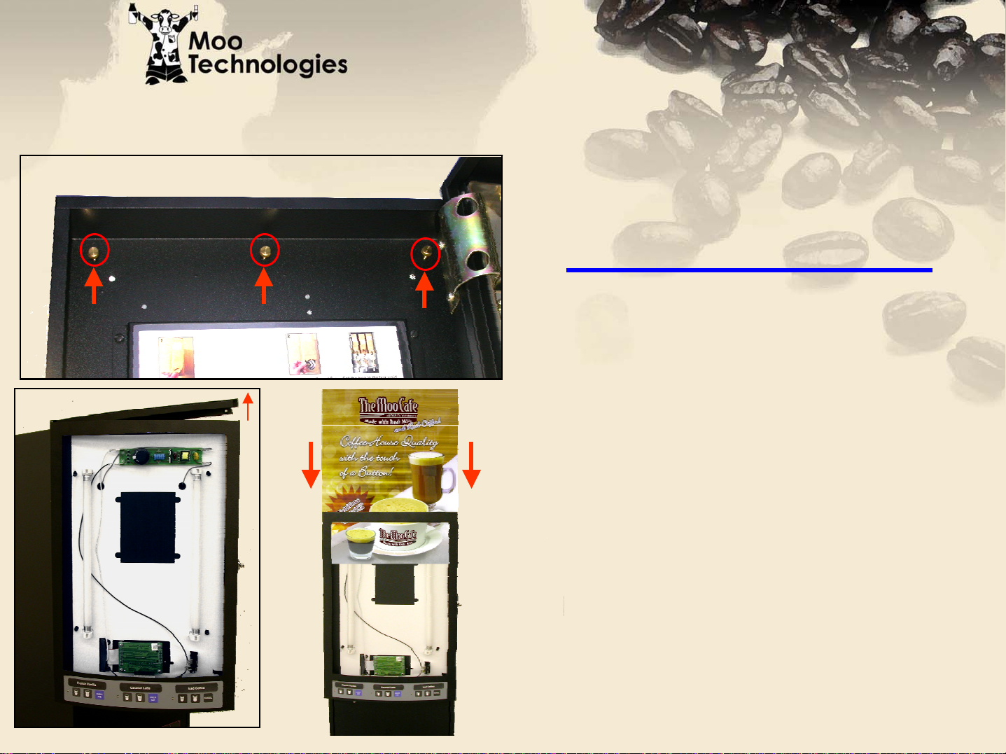
Graphic Installation
Unscrew and remove three (3)
brass thumbscrews from inside top
of door panel, then lift and remove
door cap. Peel clear plastic on
front, and white paper on rear of
Graphic. Slip Graphic into slide
guides and lower until sign is
seated at bottom of guides.
Reinstall door cap and secure with
the three (3) brass thumbscrews.
Page 15
Machine Setup
Machine Setup
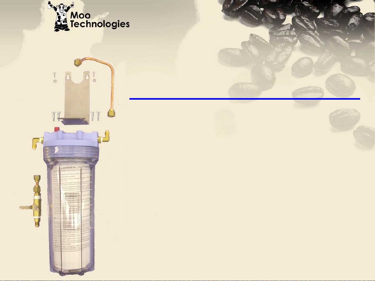
Water Filter Installation Overview
The water filter will require some assembly and
preparation prior to installing. The filter bracket
will need to be mounted to the top of the filter,
the cartridge will need to be removed from the
protective bag and the filter installation
instructions must be removed from the canister.
Page 16

Machine Setup
Machine Setup
Mounting
Screws
Water Filter Bracket
Mount water filter bracket to filter
with four (4) screws provided in
accessories bag. Assure that “outlet”
is on the right of bracket so the preformed tubing (installed in future
step) will reach unit water inlet.
Mounting
Screws
Outlet
Fitting
Page 17

Machine Setup
Machine Setup
Mounting Water Filter Bracket
Locate water inlet at upper rear of
unit. Install filter bracket using two
(2) #8 screws and star washers
provided in accessories bag.
Page 18

Machine Setup
Machine Setup
To Unit Inlet
Fitting
Tubing & Shutoff Connections
Run pre-formed water supply line
between water filter outlet and unit
water inlet.
Page 19

Machine Setup
Machine Setup
Run water supply line between water
source and shutoff inlet. It is highly
recommended to leave enough extra tubing
length to allow for serving unit. Equipment
should be installed to comply with all
federal, state and local plumbing codes.
Flow requirements are a minimum of 35psi
Water Supply Connection
To water supply
flowing pressure and a maximum of 100psi
static pressure.
Page 20

Machine Setup
Machine Setup
Drip Tray Housing
Installation
Align Drip Tray Housing guides with
Drain Support Bracket arms and
slide toward rear of unit.
Page 21

Machine Setup
Machine Setup
Drip Tray Installation
Align Drip Tray drain with Drain
Support Bracket drain receiver
and push down until seated.
Route Drain Support Bracket
hose into location drain
assuring a downward pitch to
allow for proper drainage.
Equipment should be installed
to comply with all federal, state
Note: Assure rubber gasket of drip tray is
properly seated in drain to avoid leakage.
and local plumbing codes.
Page 22

Machine Setup
Machine Setup
Drip Tray Wireform
Installation
Lower Drip Tray Wireform
into Drip Tray
Page 23

Machine Start up
Machine Start up
1. Turn on water to unit and check for leaks
2. Plug unit into electrical supply (120V,3 pole, 4 wire grounding type receptacle).
Hot water will begin filling.
3. Activate the Light Switch (toggle up) located on the inside of the door panel.
4. The LCD window will display self test message briefly, then sanitation indicators will
light. However, unit will not begin sanitizing until tank temperature reaches 160
degrees F. The sanitizing cycle may be canceled by pressing Rinse/Auto Rinse
button.
5. Allow approximately 6-8 minutes for the tank to fill. If tank does not fill within 10
minutes, a “FIL” error message will appear on LCD screen.
6. Allow up to 50 minutes for the water to reach 175 degrees. The heat up time will
depend upon the location’s water temperature and available voltage.
7. Open product door, hook up Moo products, then close door. Note that unit is
equipped with a safety lock device that will not allow product pumps to run while door
is open.
8. Set-up and calibrate the Moo Product for each channel while unit is heating up.
Page 24

Moo BIB Installation Instructions
Moo BIB Installation Instructions
Rear BIB Alignment Guide
Flap
Front BIB Guide
Round
Closure
Lay BIB on back and remove round
perforated cardboard closure
Front BIB Guide
Tubing Holders
Set BIB on product shelf just behind
front BIB guide. Align BIB tubing with
plastic tubing holder, then clamp
tubing inside holder
Lift up front cardboard flap and
remove BIB tubing, then re-close flap
Route tubing through top pump housing
cutout, then around left side of rotor and out
bottom cutout. Turn rotor assembly
counter-clockwise if necessary.
Assure front and rear BIB alignment guides
are in place before installing packaging
Turn rotor assembly counter-clockwise to
assure tubing is pinched at top and bot
Then remove red plug from tubing and install
tube over dosing head port.
tom.
Page 25

Expresso
Expresso
BIB Installation Instructions
BIB Installation Instructions
Rear BIB Alignment Guide
Expresso
Flap
Product
Adapter
Round
Closure
Lay BIB on back and remove round
perforated cardboard closure.
Remove Moo product dosing head
from Whipper Chamber and water
supply tube. Install Expresso Product
Adapter dosing head into water supply
tube and snap on Whipper Chamber.
Shipping
Cap
Lift up front cardboard flap, remove BIB
connector, then re-close flap. Remove Expresso
Product Adapter from unit accessory bag.
Route Expresso Product Adapter tubing through
bottom pump housing cutout, then around left side
of rotor and out top housing cutout .
assembly counter-clockwise if necessary. Place
tubing in plastic clip.
Turn rotor
Front BIB Guide
Assure that front and rear BIB alignment
guides are in place.
Holding Expresso BIB with connection
upwards, remove shipping cap and install
Product Adapter Connector. Set BIB on
product shelf just behind front BIB guide
Page 26

Machine Calibration Instructions
Machine Calibration Instructions
Overview:
Machine H2O settings are calibrated at the factory and normally do not need
adjustment unless a dispensing valve is replaced or the measured dispense volume
does not match the displayed setting.
Concentrate settings should be performed at initial set-up and each time the product
density (or viscosity) changes. If same product is used (i.e. just changing out an
empty box of the same product), channel does not need recalibration.
Calibration applies to the following :
A. Hot Water flow rate
B. Concentrate flow from pumps (liquid BIB)
C. Cold Water (ambient) flow rate
Note: Pull door safety switch out to place unit in “Service
Mode” during product calibration process. Pumps will not
operate and P1, P2 or P3 error codes will display if not
calibrating in “Service Mode”.
Page 27

Machine Calibration Instructions
Machine Calibration Instructions
Concentrate Calibration
Concentrate Calibration
Step 1
---
Press & hold “Settings” (middle) button
After approximately 5 seconds,
display will change to “---”
Step 2
Continue holding button until display
changes to “Con” and “Left”
Channel indicator light is displayed
(takes approximately 8 seconds),
then release “Settings” button.
---
Con
Page 28

Machine Calibration Instructions
Machine Calibration Instructions
Concentrate Calibration
Concentrate Calibration
0.30
Con
Step 3
Press “Settings” (middle) button.
Display will change to “0:30” (30 seconds).
Place measuring cup (preferably at
least a 12 fl oz graduated cup) under
the dispensing head to be calibrated
as indicated by channel light.
Page 29

Machine Calibration Instructions
Machine Calibration Instructions
Concentrate Calibration
Concentrate Calibration
0.30
Step 4
Press “Settings” button again,
machine will pump concentrate into
measuring cup for 30 seconds.
Page 30

Machine Calibration Instructions
Machine Calibration Instructions
Concentrate Calibration
Concentrate Calibration
Step 4 (continued)
When concentrate stops, read
concentrate volume (in ounces) from cup.
Enter measured value into display
Toggle left button
New Bag (+)
to increase value
Toggle right button
Rinse (-)
to decrease value
9.0 ounces
9.00
0.30
Page 31

Machine Calibration Instructions
Machine Calibration Instructions
Concentrate Calibration
Concentrate Calibration
Step 5
0.30
9.00
Press “Settings” to store settings. Display
will change to 0:30, and “Middle” Channel
Indicator light (middle dispensing head)
will illuminate.
Empty and move the measuring cup under
the middle dispensing head. Repeat steps
1-4 for the middle and right dispense head.
When Right dispense settings are stored,
display changes to “Con”.
Page 32

Machine Calibration Instructions
Machine Calibration Instructions
Water Calibration (if necessary)
Water Calibration (if necessary)
Step 1
---
Press & hold “Settings” button,
after approximately 5 seconds
Display will change to”- - -”
Step 2
Continue holding button for
approximately 8 more seconds, (display
---
H2O
Con
changes to “Con” and “Left”
Channel indicator light is displayed.
Without releasing button, continue
holding button for an additional 8
seconds, display will change to H2O.
Page 33

Machine Calibration Instructions
Machine Calibration Instructions
Water Calibration (if necessary)
Water Calibration (if necessary)
H2O Ambient Calibration is a factory. Settings should not need re-calibration unless the measured dispense volume
does not match the displayed setting.
Note:
Continuing to step #3 begins the calibration
the unit for Hot Water settings. If you would
Cld
like to skip hot water settings and proceed
directly to Cold Water settings, perform the
following step.
Press “Rinse” (right) button three times.
H2O
Channel indicator light will move to middle
position with first press, right position with
second press and display will change to
“Cld” (Cold) after third.
Continue with step #3 for either Hot or Cold water calibration.
Page 34

Machine Calibration Instructions
Machine Calibration Instructions
Water Calibration
Water Calibration
Step 3
Press “Settings” (middle) button.
Display will change to “0:30” (30 seconds).
Place measuring cup (preferably at least a
32 fl oz graduated cup) under the
dispensing head to be calibrated as
indicated by channel light.
0.30
Con
Page 35

Machine Calibration Instructions
Machine Calibration Instructions
Water Calibration
Water Calibration
0.30
Step 4
Press “Settings” button again,
machine will pump water into
measuring cup for 30 seconds.
Page 36

Machine Calibration Instructions
Machine Calibration Instructions
Water Calibration
Water Calibration
Step 4 (continued)
When concentrate stops, read
water volume (in ounces) from cup.
Enter measured value into display
Toggle left button
New Bag (+)
to increase value
Toggle right button
Rinse (-)
to decrease value
24.0 ounces
24.0
0.30
Page 37

Machine Calibration Instructions
Machine Calibration Instructions
Water Calibration
Water Calibration
Step 5
0.30
9.00
Press “Settings” to store settings. Display
will change to 0:30, and “Middle” Channel
Indicator light (middle dispensing head)
will illuminate.
Empty and move the measuring cup
under the middle dispensing head.
Repeat steps 3-5 for the middle and right
dispense heads.
Page 38

Machine Calibration Instructions
Machine Calibration Instructions
Step 7
Cld
In Hot water calibration mode, when right
dispense settings are stored, display
changes to “Cld” prompting you to repeat
steps 3-5 for Cold Water calibration of each
9.00
dispensing head.
In Cold water calibration mode, when right
dispense settings are stored, display
changes to “Pro” (program).
With “Pro” displayed, Press “Settings” twice
to enter settings as default and exit program
mode. (Note: En4 is a factory setting and
should not be changed). Display will go
blank once settings are entered.
After Hot water
programming
Pro
9.00
After Cold water
programming
Page 39

Programmable Buttons
Programmable Buttons
(3 per channel)
(3 per channel)
Each button on the door switch is programmable for the following:
A. Button Enable - Enables or disables each individual button.
Example: Enable center button only for a manual dispense, hot or cold
product.
PUSH
HERE
French Vanilla Latte
PUSH
HERE
Left Channel &
Dispensing Valve
Indicates buttons that have been enabled
Indicates buttons that have been disabled
Middle Channel &
Dispensing Valve
Unsweetened
Cappuccino
PUSH
HERE
Sweetened
Cappuccino
PUSH
HERE
Right Channel &
Dispensing Valve
Page 40

Programmable Buttons
Programmable Buttons
B. Portion Control Allows for the ability to set a volume dispense
( in ounces) for any button.
Example: Program the 1stbutton for each dispense for a
small cup dispense, the center button for a large
cup dispense, and the 3rdbutton for a manual dispense
French Vanilla Latte
Small
Large
MANUAL
Manual
Unsweetened
Cappuccino
MANUAL
Sweetened
Cappuccino
MANUAL
Page 41

Programmable Buttons
Programmable Buttons
C. Hot/Cold Water Dispense Allows customer choice of hot or cold
(ambient) dispense per button
Example: Program the 1st& 3rdbuttons on each channel
“Hot” & “Iced” (ambient).
French Vanilla Latte
Iced Iced IcedHot Hot Hot
Indicates buttons that have been disabled
Unsweetened
Cappuccino
Sweetened
Cappuccino
Page 42

Multi Level
Multi Level
Programming
Programming
Instructions
Instructions
Page 43

Product Ratio Instructions
Product Ratio Instructions
Step 1
Press and hold Settings
button until display
changes to
Step 2
Press and hold New Bag
button until display
changes to
Step 3
Press desired button on
front screen to program.
Display will change to a
Ratio Value
rAt
3.0
Toggle Ratio Value with:
New Bag (+) to increase
Rinse (-) to decrease
When desired ratio value is
obtained, press Set-up button
Step 4
to lock-in setting
Ratio value is now locked in.
Display changes to
Repeat step 3 & 4 for
remaining flavor buttons
rAt
Page 44

Portion Control
Portion Control
Step 1
Press and hold Settings
button until display
changes to
Step 2
Press and hold New Bag
button until display
changes to
Step 3
Press desired button on
front screen to program.
Display will change to a
Ounce Volume Value
Por
3.0
Step 4
Toggle Ratio Value with:
New Bag (+) to increase
Rinse (-) to decrease
When desired volume value is
obtained, press Set-up button
to lock-in setting
Portion Control value is now
locked in. Display changes to
Por
Repeat step 3 & 4 for
remaining flavor buttons
Page 45

Button--
Button
Step 1
Press and hold Settings
button until display
changes to
Manual Dispense ––
Manual Dispense
Enable/Disable
Enable/Disable
Step 4
Toggle Ratio Value with
Step 2
Press and hold New Bag
button until display
changes to
Step 3
Press desired button on
front screen to program.
Display will change to a
Ounce Volume Value
Por
3.0
New Bag (+) or Rinse (-)
buttons until display reads
on
If “off” is selected, button is disabled.
If “on” is selected, button is set for
Manual Dispense.
Press center button to store selection
Repeat step 3 & 4 for remaining flavor
or
buttons
off
Page 46

Hot/Cold Water Selection
Hot/Cold Water Selection
Step 1
Press and hold Settings
button until display
changes to
Step 2
Press and hold New Bag
button until display
changes to
Step 3
Press desired button on
front screen to program.
Display will change to a
Temp Option
o F
Hot
Step 4
Press New Bag (+) or Rinse (-)
buttons until display reads
“hot” or “cold (ambient)” water
temperature
Hot
Press Settings button to store selection
Temp choice is now locked in for button.
or
Cl d
Display changes to
Repeat step 3 & 4 for remaining flavor
buttons
o
F
Page 47

Whipper
Whipper
Step 1
Press and hold Settings
button until display
changes to
Step 2
Press and hold New Bag
button until display
changes to
Step 3
Press desired button on
front screen to program.
Display will change to
“On” or “Off”
Motor ––
Motor
bin
on
Enable/Disable
Enable/Disable
Step 4
Press New Bag (+) or Rinse (-)
buttons until display reads
on
If “off” is selected, Whipper is disabled.
If “on” is selected, Whipper enabled.
Press center button to store selection
or
off
Repeat step 3 & 4 for remaining flavor
buttons
 Loading...