

Page 1
KB-TCF KB-3F
Man. PN: 781224
Rev. 20170309
NEWCO ENTERPRISES
INSTALLATION, OPERATION, AND SERVICE MANUAL FOR
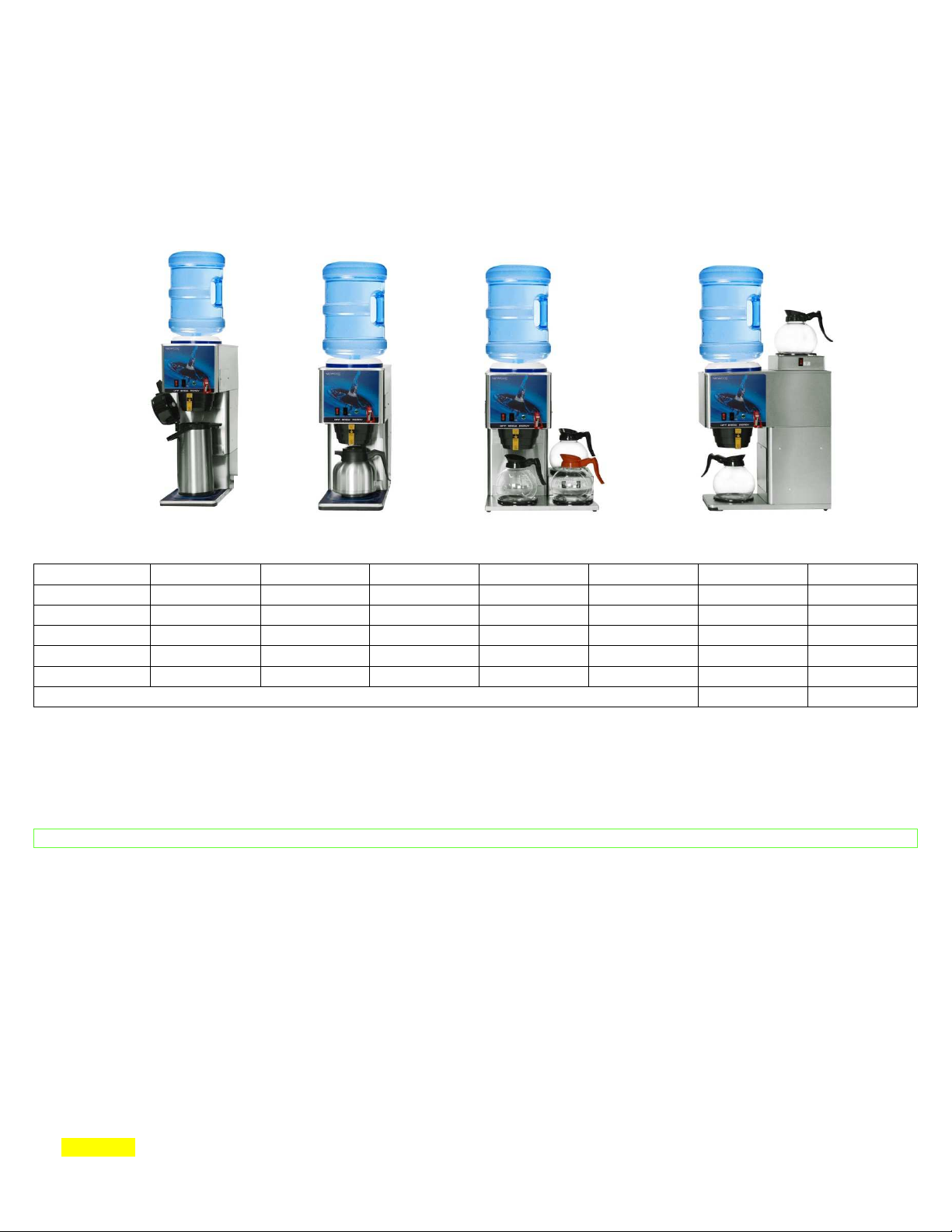
KB SERIES BOTTLED WATER BREWERS
KB-APF/LDF
KB-2F
Model Warmers Width Depth Height Weight Watts Amps
KB-1F 1 9 1/2" 18” 20 1/8” 34 1500 12.5
KB-2F 2 18” 9 1/2" 22 3/8” 39 1600 13.3
KB3-F 3 16 1/2" 18” 20 1/8” 43 1700 14.2
KB-TCF 0 9 1/2" 18” 20 1/8” 34 1400 11.7
KBAPF/LDF*
*We recommend up to 3 gallon bottles only due to stability, unless anchored to wall.
WARNING – Read and follow installation instructions before plugging or wiring in machine to electrical circuit. Warranty
1.) Place bottle on top of brewer with neck of bottle extending into receiving hole.
2.) Hold faucet open until water flows from it. Allow one minute for automatic leveling of water in tank. Plug or wire brewer to
appropriate voltage circuit as indicated on serial tag. Place decanter/carafe/airpot under brew basket and turn lower warmer
switch to the “ON” position. Depress brew start switch & check volume of water delivered into decanter/carafe/airpot. Adjust
timer to deliver desired amount of water. Turn timer dial clockwise to increase volume of water, and counter clockwise to
decrease volume.
3.) Allow 10 to 15 minutes for water in tank to heat to brewing temperature. Water has reached brewing temperature when
thermostat clicks off and heating noise stops. Green ready light will be lit on models so equipped. Empty vessels and
replace.
4.) Run one cycle to check for proper temperature setting with an accurate thermometer. Take the temperature of the water at a
point below the brew basket opening, at the start of the brew cycle, and when the vessel is half full. Recommended
temperature is approximately 195°F.
5.) In higher altitudes [5,000 feet above sea level] the thermostat may have to be adjusted to a lower temperature to prevent
boiling.
6.) CAUTION: On faucet models the water faucet will dispense hot water when the handle is depressed. The faucet may be
operated during brew cycle.
0 9 1/2" 18” 26 1/2" 42 1400 11.7
FILL BREWER TANK WITH WATER BEFORE CONNECTING TO POWER SUPPLY!
Vessels Not Included
INSTALLATION INSTRUCTIONS
Page | 1
Page 2

Tanks
Containers
Miscellaneous
Parts
Warming Plates
Brew Baskets and Rails
COFFEE PREPARATION PROCEDURES
• Place filter into brew basket.
• Put the proper amount of coffee into the filter.
• Slide the brew basket into holder.
• On warmer models, place empty decanter on warmer located directly under the brew basket and turn
corresponding warmer switch to “ON” position. On thermal models, place dispenser or airpot directly under
the brew basket.
• Press brew start switch. [Brew cycle may be canceled by turning the red rocker switch back to the “OFF”
position.]
• Hot water will be delivered through the spray head. This distributes the hot water evenly over the coffee
grounds within the brew basket. The coffee brew will drain from the brew basket into the decanter below.
• The resultant coffee brew should be crystal clear and have the desired properties attainable through excellent
extraction.
• TURN OFF WARMER WHEN NOT IN USE. [Illuminated red rocker switch indicates warmer is on.]
• To clean brew basket simply remove from the brew rails and dump coffee filter into waste basket. The
brewing process, as described above, can now be started again.
• On units with a “CHANGE BOTTLE” light, this indicator will come on at any time the bottle empties. The bottle
should be changed at this time. The brewing circuitry will be disabled until bottled water supply is replenished.
KB SERIES – PARTS LIST
781178 Tank Assy., KB1F,KB3F,KBAP/LD 100510 12 Cup Glass Decanter [Decaf]
781287 Tank Assy., KB1 & KB3 100550 12 Cup Glass Decanter [Regular]
781219 Tank Assy., KB2F 112005 Thermal Dispenser, 85 oz. [Short]
781287 Tank Assy., KB2 112006 Thermal Dispenser, 85 oz. [Tall]
781217 Receiving Tank/Bracket Assy. without Probe 120795 Airpot, 2.2L Diagonal Lever KK Series
781194 Receiving Tank/Bracket Assy. with Probe 120818 Airpot, 2.2L Stainless Steel Lever KK
102580 Main Element Assy., 1400W 120V 111445 Thermal Server, 1.9L Short Vaculator
111592 Manual Hi-Limit Thermostat, 221F 109115 Thermal Server, 1.9L S/S Coffee Butler
781181 Gasket, Receiving Tank
102770 Faucet with Red Handle
100008 Plate, Porcelain Black 152114 Deltrol Solenoid Valve
100010 Warming Plate Assy., 100W 120V Black 152130 Valve Repair Kit, Deltrol
100187 Warming Element, 100W 120V 100024 5-hole Spray Head, S/S
110985 Brew Basket Assy., Black Vac. 201173 Spray Head Nut
110987 Brew Basket Assy., Color Changing Vac. 101365 Timer Only, 25004-4
781030 Right-hand Brew Rail 781195 Liquid Level Board, KB Series
781031 Left-hand Brew Rail 781220 Harness, Tank-SW-Sol-Vio/Wh
781211 Timer Harness Only
100022 Power Cord Assy., 14/3 15Amp 120V
773300 Thermostat Assy., 4.78” Robertshaw
201985 Start Switch, Momentary Black
100085 Red Rocker Switch, Lighted
781212 Ready Light Assy., Green KB series
201189 Pilot Light with Terminals
100078 Bumper Foot with Screw
100025 Spray Head Gasket
Page | 2
Page 3

WARRANTY
Applies to all equipment manufactured after 2/1/2017. This warranty supersedes
all other previous warranties that are currently in manuals.
• Newco warrants equipment manufactured by it for 1 year parts and labor.
• Accessories and Dispensers 1 Year parts only.
• Electronic Circuit and Control Boards- 3 years parts, 1 year labor.
• Equipment manufactured by others and distributed by Newco- please see original equipment manufacturers
warranty, Newco will follow.
These warranty periods run from the date of sale Newco warrants that the equipment manufactured by it will be
commercially free of defects in material and workmanship existing at the time of manufacture and appearing within the
applicable warranty period. This warranty does not apply to any equipment, component or part that was not manufactured
by Newco or that, in Newcoʼs judgment, has been affected by misuse, neglect, alteration, improper installation or
operation, relocation or reinstallation, improper maintenance or repair, incorrect voltage applied to the unit at any time,
damage or casualty. This warranty does not apply to any equipment failures related to poor water quality, excessive lime
and chlorine and non-periodic cleaning and descaling. Warranty is null and void if muriatic or any other form of
hydrochloric acid is used for cleaning or deliming. In addition, this warranty does not apply to replacement of items
subject to normal use including but not limited to user replaceable parts such as faucet seat cups, sight gauge tubes,
washers, o-rings, tubing, seals and gaskets.
This warranty is conditioned on the Buyer 1) giving Newco prompt notice of any claim to be made under this warranty
by telephone at (800) 556-3926 or by writing to 3650 New Town Blvd, Saint Charles, MO 63301; 2) if requested by Newco,
shipping the defective equipment prepaid to an authorized Newco service location; and 3) receiving prior authorization
from Newco that the defective equipment is under warranty.
THE FOREGOING WARRANTY IS EXCLUSIVE AND IS IN LIEU OF ANY OTHER WARRANTY, WRITTEN OR ORAL,
EXPRESS OR IMPLIED, INCLUDING, BUT NOT LIMITED TO, ANY IMPLIED WARRANTY OF EITHER MERCHANTABILITY
OR FITNESS FOR A PARTICULAR PURPOSE. The agents, dealers or employees of Newco are not authorized to make
modifications to this warranty or to make additional warranties that are binding on Newco. Accordingly, statements by
such individuals, whether oral or written, do not constitute warranties and should not be relied upon.
If Newco determines in its sole discretion that the equipment does not conform to the warranty, Newco, at its exclusive
option while the equipment is under warranty, shall either 1) provide at no charge replacement parts and/or labor (during
the applicable parts and labor warranty periods specified above) to repair the defective components, provided that this
repair is done by a Newco Authorized Service Representative; or 2) shall replace the equipment or refund the purchase
price for the equipment.
THE BUYERʼS REMEDY AGAINST NEWCO FOR THE BREACH OF ANY OBLIGATION ARISING OUT OF THE SALE OF
THIS EQUIPMENT, WHETHER DERIVED FROM WARRANTY OR OTHERWISE, SHALL BE LIMITED, AT NEWCOʼS SOLE
OPTION AS SPECIFIED HEREIN, TO REPAIR, REPLACEMENT OR REFUND.
In no event shall Newco be liable for any other damage or loss, including, but not limited to, lost profits, lost sales, loss
of use of equipment, claims of Buyerʼs customers, cost of capital, cost of down time, cost of substitute equipment,
facilities or services, or any other special, incidental or consequential damages.
Page | 3
Page 4

TROUBLE SHOOTING GUIDE
SYMPTOM POSSIBLE CAUSE WHAT TO CHECK REMEDY
CAN’T START BREW CYCLE 1. No Water
2. No Power
3. On/Off Switch
4. Brew Start Switch
5. Timer/Timer Harness
Timer/Probe & Harness
6. Solenoid Valve
NO HOT WATER 1. Tank heater
2. Hi-limit thermostat or main
thermostat
STEAMING/SPITTING
AROUND FUNNEL
FAUCET WATER TOO SLOW 1. No Water 1. (A) Water bottle (B) Faucet
DRIPPING 1. Not siphoning properly 1. Water should flow freely
DRY COFFEE REMAINING IN
BREW BASKET AFTER
BREWING
1. Main Thermostat
2. High Altitude
1. Filter
2. Not siphoning properly
3. Improper loading of brew
basket
1. Water bottle is empty?
2. Fuse or circuit breaker,
power cord & plug
connections
3. Switch continuity [normally
closed 1 & 2]
4. Switch continuity [normally
open]
5. Leads to solenoid, switches,
& level sensor probe.
6. (A) Voltage at solenoid
valve terminals, start a brew
cycle & check for 120V AC
(B) If voltage is present at
terminals, check water on
the inlet side of solenoid
valve
1. Check voltage at the tank
terminals, voltage should be
as indicted on the serial tag
2. Check voltage between the
white wire on the tank &
incoming terminal [blue
wire] on the hi-limit
thermostat, then the
outgoing terminal [black
wire] on the hi-limit
thermostat
1. Thermostat points stuck or
out calibration
2. Located above 5,000 feet
clogging
from the spray head
1. Correct filters being used?
2. Refer to “Dripping” step 1
3. Filter & coffee in brew
basket
1. Replace empty bottle with
new one
2. Replace or reset circuit
protector as required, unit
should be plugged in
securely
3. If On/Off switch does not
make and break contact
replace it
4. If brew start switch does not
make & break contact,
replace it
5. Make sure these
connections are tight, if all
checks out ok replace timer
6. (A) If voltage is not present
at terminals, refer to steps 2
thru 5 (B)If voltage is
present at terminals, water
is present at the inlet side
but not at the outlet side of
the solenoid valve replace it
1. (A) If correct voltage is
present at the tank heater
terminals & water not
heated, replace the tank’s
heating element (B) If
voltage is not present at the
tank heater terminals refer
to step 2 (c) if incorrect
voltage is present at the
tank heater terminals, check
voltage at outlet
2. (A) If voltage is present on
the incoming terminal of the
hi-limit thermostat, but not
on the outgoing terminal,
replace the hi-limit
thermostat (B) Check the
voltage between the black &
white wire on the
receptacle, if voltage is not
present check outlet or
circuit breaker (C) If voltage
is not present on the
incoming terminal of the hilimit thermostat replace the
main the main thermostat
1. (A) Adjust thermostat (B)
Thermostat should be
calibrated or replace
2. See installation instructions
1. (A) Replace empty bottle
with new one (B) Clean or
rebuild faucet
1. (A) Clean spray head holes
(B) Check tightness of spray
head tube
1. Insert proper filter
2. Refer to “Dripping” step 1
3. Filter centered, coffee bed
level
Page | 4
Page 5

TROUBLE SHOOTING GUIDE
SYMPTOM POSSIBLE CAUSE WHAT TO CHECK REMEDY
WEAK COFFEE 1. Filters
2. Not siphoning properly
3. Improper loading of brew
basket
COLD WARMER STATION 1. Warmer – defective
2. Warmer ON/OFF switch
3. Bad harness
CONDENSATION ON THE
INSIDE OF CABINET
WATER KEEPS RUNNING 1. 1.Solenoid Valve
1. Tank lid gasket
2. Spray head tube assy.
3. Thermostat grommet
4. Receiving pan nut
5. Main thermostat set above
201°F
2. Start Switch
3. Timer
1. Are the correct filters being
used?
2. Refer to “Dripping” step 1
3. Filter & coffee in brew
basket
1. Voltage at warmer terminals
should be 120V AC
2. If voltage is not present on
warmer terminals check
continuity of switch
3. Check connections between
harness & switch, and
between switch & warmer
1. Nicks or cuts in the gasket
2. Tightness of assembly to lid
3. Tight fit, nicks, or cuts
4. Receiving pan nut loose
5. Check thermostat
calibration
1. Refer to “DRIPPING” step 1
2. Remove wires from switch
& check continuity
3. Solid state timers are not
repairable, if timer will not
shut off, replace timer
1. Insert correct filter
2. Refer to “DRIPPING” step 1
3. Filter centered, coffee bed
level
1. If voltage is present on
terminals, but warmer will
not heat, replace warmer
2. If switch does not make &
break continuity when
turned off, replace switch
3. All connections should be
tight
1. Replace gasket
2. Tighten spray head tube
assy. to tank lid
3. Adjust or replace grommet
4. Tighten nut
5. Calibrate or replace
thermostat
1. Refer to “DRIPPING” step 1
2. If start switch does not
make or break contact,
switch should be replaced
3. Replace timer
Page | 5
Page 6
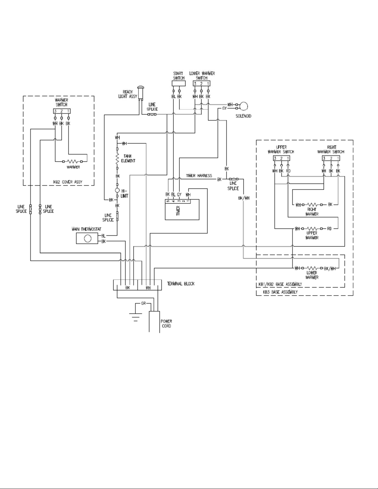
WIRING DIAGRAM
Page | 6
Page 7

NOTES
Page | 7
Page 8

NOTES
Page | 8
 Loading...