

Page 1
Manual PN 105193
Issued 0299
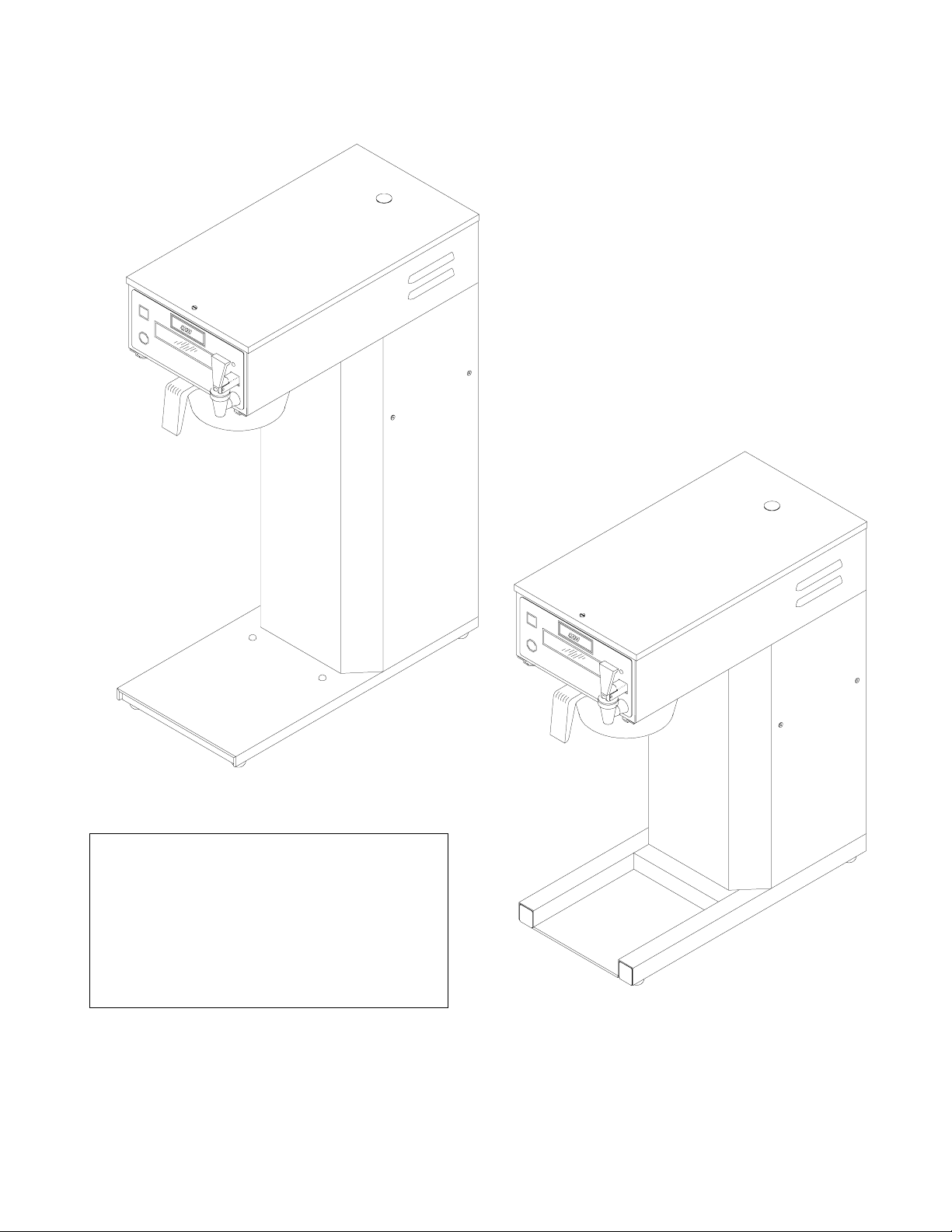
IQ 2000 P
IQ-D
OPERATION MANUAL
Installation, Setup and
•
Operating Instructions.
Troubleshooting Guide.
•
Wiring Diagram.
•
IQ-LD
GREAT CANADIAN SYSTEMS, INC.
1-800-267-3555
Page 2
Installation Instructions
WARNING:
circuit. Warranty will be void if machine is connected to any voltage other than that specified on the name plate.
PLUMBER'S INSTALLATION INSTRUCTIONS
1) Plumb brewer in to water supply using 1/4 inch copper or plastic tubing. Flush water line before installing
2) Water pressure should be at least 20 lbs. For less than a 25 ft. run, use 1/4" tubing and connect to 1/2" or
3) Once the brewer is pressurized plug the brewer into a 120 volt power supply.
Brewer Fill Program
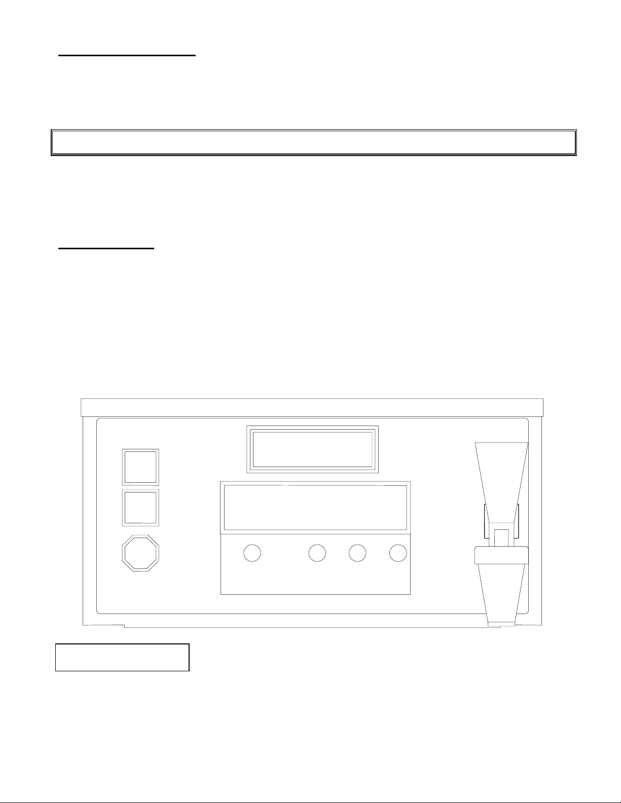
program or service mode you will need to attach a service template to the faceplate of the unit in order to locate
the buttons. Attach one of the self stick templates to the faceplate aligning it with the display window edges and
bottom border as shown in Fig 1 below.
Depress and hold down both the Brew and Cancel buttons located on the brewer face plate (See Fig 1 below).
Continue to hold the two buttons in while turning the ON/OFF switch to the ON position. The brewer display will
indicate to "Please Wait" as it initializes the Program/Service mode. Continue holding the brew and the cancel
button until the brewer enters the Program/Service main menu (approximately 5 seconds).
- Read and follow installation / setup instructions before plugging or wiring in machine to electrical
CAUTION:
brewer to remove sediment. Brewer should be connected to COLD WATER LINE for best operation.
larger water line. The inlet water fitting extending from the solenoid valve on the back of the brewer is a
1/4" compression type fitting.
Programming is done through the 4 hidden buttons located under the display. Prior to accessing the
Turn the main ON/OFF switch located on the lower left front of brewer column to the OFF position.
Power to brewer must be OFF before proceeding with plumbing installation.
Figure 1 - Faceplate
IQ2000
BREW
HALF
BREW
CANCEL
ENTER
IQ
Service Template
Select Mode
Program Service
The brewer fill process will take between 4 and 5 minutes. The tank heater in the brewer will automatically turn on
when the water makes contact with the heater safety probe. This will prevent damage to the tank heater from
turning on the element to early. The brewer will continue to fill until the water level in the tank reaches the upper
probe. The Tank Fill Program does not have a maximum run time to provide overfill protection. The brewer
heating system will take approximately 15 minutes to reach the preset temperature of 205 degrees.
This is the Program/Service main menu. Use the Select key to choose the service
mode. Continue to depress the Select button until you reach the "Fill Tank Press
Brw1" message. Depress the Brew switch and the brewer filling process will begin.
SELECT
-
+
HOT WATER
- 2 -
Page 3

Initial Setup Instructions
1) Once the brewer tank has been filled the brew time and temperature may be checked and adjusted as
required. Place a suitable decanter in place below the brew basket to catch water. The IQ features a dump valve
system so brewing begins immediately when the Brew switch is depressed, providing the water level in the tank is
up to the upper water probe. Note: the tank also contains a second longer probe which is a heater safety probe.
This probe will tell the control board when the water level is high enough to supply power to the tank element. It
also will call for power to be shut off to the element should the water level fall below it.
2) Depress the start switch to run a brew cycle and check the volume of water delivered into the container. If
the tank temperature is up to the preset level or if the auto arm feature has been disabled the unit will begin
brewing immediately. Otherwise the brewer will go into the auto arm mode and the display will indicate "Brew
Cycle Activated" to indicate that the unit is in the brew mode but is not up to temperature (Note: To accelerate the
set up time auto arm may be disabled as noted in the Program Options section on the following page). When the
tank reaches the preset temperature the fill portion of the brew cycle will begin. The tank lid must be in place for
proper unit operation. The brew cycle may be canceled by depressing the Cancel button if desired.
3) Allow water to finish draining from the unit. Note that the "Coffee Brewing" message should continue to
display until all liquid has finished draining from the unit. If not you will need to adjust the Buzzer Delay. After the
brew cycle has finished check volume of water in the container. Empty the decanter and replace below brew
basket. If the volume is short it will be necessary to increase the brew time. Decrease the brew time if to much
fluid is obtained. Adjust the brew time and buzzer delay as described in the Program Options section on the
following page.
4) Allow the water in the tank to heat to brewing temperature (relay will click off and heating noise will stop).
Run one brew cycle to check for the proper temperature setting with an accurate thermometer. Take the
temperature of this water at a point below the brew basket opening, at the start of the brew cycle and when the
decanter is half full. Recommended temperature of the water is approximately 195 F. The actual tank water
temperature may also be taken by removing the plug on the brewer top cover and inserting a thermometer through
the Silicone plug in the tank lid. The brewer features an electronic temperature control circuit and the temperature
may be adjusted with the control board as explained in the Program Options section on the following page.
5) In higher altitude locations (5000 feet above sea level) the tank temperature may have to be adjusted
lower to prevent boiling.
6)
Coffee Preparation Procedures
1) Place filter into brew basket.
2) Put the proper amount of coffee into the filter.
3) Slide the brew basket into holder.
4) Place the appropriate empty decanter into position below the brew basket. For airpots first open lid and
5) Press Brew button.
6) If the auto arm feature is enabled and the brewer is not up to temperature the "Brew Cycle Activated"
7) Hot water will be delivered through the sprayhead. This distributes the hot water evenly over the coffee
8) The "Coffee Brewing" message should continue to display until all the liquid has finished flowing from the
9) The resultant coffee brew should be crystal clear and have the desired properties attainable through
10) To clean brew basket simply remove from brew rails and dump filter into waste basket. The brewing
CAUTION:
remove pump stem. For other dispensers remove the lid unless it is a brew through design.
message will display indicating that the brewer is heating and will begin to brew immediately after the
heating cycle is complete. Do not remove decanter. Brew cycle may be canceled by depressing the
Cancel button. Display will return to "Ready To Brew" and other programmed messages.
bed within the brew basket. The coffee brew will drain from the brew basket into the decanter below.
brew basket. Do not remove decanter until the brewing process has stopped and all liquid has stopped
flowing from the brewbasket.
excellent extraction.
process, as described above, can now be started again.
The water faucet will dispense hot water when the handle is pulled.
- 3 -
Page 4
Program and Service Mode Functions
Programming is done through the 4 hidden buttons located on the brewer faceplate under the display.
Prior to accessing the program or service mode you will need to attach a service template to the faceplate of the
unit in order to locate the buttons. Attach one of the self stick templates to the faceplate aligning it with the display
window edges and bottom border as shown in Fig 1 on page 2.
To enter either the Program or Service Mode:
Turn the main ON/OFF switch located on the lower left front of brewer column to the OFF position.
Depress and hold down both the Brew and Cancel Buttons located on the brewer face plate. (See Fig 1, Page 2).
Continue to hold while turning the ON/OFF switch to the ON position. The brewer display will indicate to please
wait as it initializes the program/service mode. Continue holding the brew and the cancel button until the brewer
enters the Program/Service main menu (approximately 5 seconds).
Select Mode
Program Service
This is the Program/Service main menu. Use the Select key to choose either the
Program or Service mode. The program mode is used to set custom settings such
as brew times, buzzer type, tank temperature, enable power save or auto arm, etc.
The service mode is used for initial brewer fill, to display and clear error messages, to view total brew cycles, and
to view/reset the brew cycles since service.
An explanation of the various features for both modes is outlined in the following sections. Note that if at
any point after entering this menu the brewer detects that there has been no activity on the keypad for 1 minute it
will exit to the ready/standby mode. It will then be necessary to follow steps outlined above to return to the program
or service mode. If an option or feature has been changed without pressing enter prior to this occurring the change
will be lost.
Program Options
Table 1 - Summary of Program Mode Options/Features
Factory
Option Program Options/Value Range
Brew Time #1 10 Sec - 5 Min, 20 Sec 3:25 Dump valve open time for brew 1.
Brew #2 Enable Yes, No No Optional second brew setti ng using hidden key.
Brew Time #2 10 Sec - 5 Min, 20 Sec 1:30 Dump valve open time for brew 2.
Buzzer Delay 10 Sec - 2 Min 1:00 Drain time from basket for brews 1 and 2.
Auto Arm Enable Y es, No Yes Ensures optimum brew temperature.
Brew Time Remaining Yes, No Yes Display tim e remaining during the brew cycle.
Temperature Setpoint 170° F - 212° F 205 Water hol di ng temperature in tank.
Power Save Enable Yes, No Time is f actory set at
2 hours. May not be changed.
Buzzer Type Burst, None, Steady, Single Pulse, Double
Pulse
Keypad Beep Enable Yes, No Yes Audible tone to ensure keys are fully
Service Cycles 0 - 65535 500 Brew Cycles to run before dis pl a yi ng t he Call
Exit Pgm/Srv Mode Yes, No N/A Exit from programing m ode to "Ready To
Setting Description
Yes Drops tank temperature to 170° F during
periods (2 hours) of non use to save energy.
Steady Signal for the complet i on of the brew cycle.
depressed.
For Service Message for routine m ai ntenance.
Brew".
Brew Time #1
3:30
This is the length of time which the dump valve will remain open to allow water to
flow over the coffee grounds. It is the active portion of the brew cycle. The Select
key may be used to choose a numeral in the displayed time to change and the "-"
or "+" keys may be used to change the selected numeral up or down as required to obtain the desired brew time.
Note that when setting brew time the display changes by 1 numeral each time the button is depressed. The
minimum time which may be programmed is 10 seconds and the maximum time is 5 minutes and 20 seconds.
Depress enter to save the programmed brew time.
Brew #2 Enable
Yes No
This option allows a second brew function to be programmed thereby giving the
user multiple volume brewing capability. Brew #2 is the brew cycle which would be
- 4 -
Page 5

initiated by depressing the hidden brew button labeled in fig 1, page 2 as HALF BREW. If this feature is desired
use the Select button to choose "Yes". Select "No" to disable Brew #2.
Brew Time #2
1:45
If you answered yes to the previous option you will be asked to set the brew time
for this function. Follow the steps previously outlined for Brew Time #1 above. The
minimum and maximum program times are the same as noted for Brew #1.
Buzzer Delay
0:40
the second portion of the brew cycle. The minimum buzzer delay time is 10 seconds and the maximum is 2
minutes. If a buzzer is not desired it may be turned off by selecting "None" under Buzzer Type below. Note that
Brew #1 and Brew #2 both use the same buzzer delay time so the longer delay time should be used.
Auto Arm Enable
Yes No
preventing the decanter from being removed prematurely. When the tank reaches the preset temperature level the
brew cycle will begin and the display will indicate "Coffee Brewing".
Brew Time Remaining
Yes No
Temperature Setpoint
- * +
display window to decrease or increase the tank temperature as desired. The temperature at the low end of the
range is approximately 170 degrees and at the upper end is approximately 212 degrees.
Power Save Enable
Yes No
the switch on the column to the OFF position when power save was to be activated. Power save is based on the
brewing activity. When the brewer has not been used for a period of 2 hours the unit will go into Power Save
mode. When this feature is not enabled the tank temperature will be maintained at the brew set point temperature.
(The switch on the column now turns off power to the brewer disabling all brewer functions.)
This function is to set the delay for the buzzer which indicates that the coffee is
finished brewing. This delay is intended to account for the time from which the
dump valve shuts off until the coffee finishes dripping from the brew basket. This is
The auto arm function will not allow the brew cycle to start until the water
temperature is at the preset temperature level. If the brew button is pressed while
the tank is heating the display will indicate "Brew Cycle Activated" to aid in
Answering yes enables the brew time remaining to be displayed during the brew
cycle. The Brew Time and the Buzzer Delay
time. Coffee Brewing and Time Remaining will display throughout the brew cycle.
This is the method for controlling the water temperature in the tank. It is similar to
the function of a thermostat knob. Use the "-" or "+" keys to move the * (asterisk)
back and forth between the "-" (decrease) and the "+" (increase) symbols in the
When power save is enabled the brewer will allow the tank temperature to drop to
the standby temperature of approximately 170 degrees after a period of inactivity in
order to reduce power consumption. On previous models it was necessary to turn
are added together for the total brew
Buzzer Type
Burst
buzzer function.
Keypad Beep Enable
Yes No
function.
Service Cycles
00800
even though this message is displayed. Note that the name and telephone number which will be displayed may be
programmed as outlined in the Custom Message Programing Section under message number "SRV".
Exit Pgm/Srv Mode
Yes No
Program and go back through the program items listed above or you may select Service and review or set those
items. Use the select button to choose Yes or No and then depress Enter. If the brewer detects that there has
been no activity on the keypad for 1 minute it will exit to the ready/standby mode by itself.
There are 5 possible selections for the buzzer type indicating the end of a brew
cycle. They are Burst (a series of burst), None, Steady, Single Pulse or Double
Pulse. Use the select key to make your selection. Select None to disable the
When enabled this option allows a short audible tone to be sounded whenever a
key is depressed to provide audible reassurance that the button was indeed
pressed and the function initiated. Select Yes to enable and No to disable this
This feature allows you to program in the number of brew cycles which you want to
run before the brewer automatically displays the "* Call For Service *" message so
that routine maintenance may be performed. The brewer will continue to oper-ate
After programing the Service Cycles this message will prompt you to exit the
program/service mode. Select Yes to exit the program mode. If you select No you
will be returned to the Program/Service menu at which time you may select
- 5 -
Page 6

Service Options and Troubleshooting
Table 2 - Summary of Service Mode Options/Messages
Message Service Function/Message Description
Fill Tank Press Brw1 Press BREW key to fill tank when
displayed. No maximum run time.
Cycles Since Service Depress '-' and '+' key to clear. Displays the brew cycles since message was last
Total Cycles Information only. Can not change. Cumulative brewer cycles.
Error Messages Depress '-' and '+' key to clear.
Err: Fill Probe
Err: Safety Probe
Err: Open Tmp Sensor
Err: Shrt Tmp Sensor
Err: Bad Heater Elem
Err: Faucet Timeout
Use for initial setup to fill tank.
cleared.
Cause:
Fill solenoid runs more than 5 consecutive min.
Water has fallen below heater safety probe.
Thermistor circuit break.
Thermistor circuit short.
Element heating time exceeded 30 minutes.
Faucet open for more than 4 consecutive min.
Fill Tank Press Brw1
Cycles Since Service
00150
value set in Service Cycles as outlined above. To clear the number press and hold both the "-" and "+" keys
simultaneously until the number is cleared (approximately 5 seconds).
Total cycles
01140
Error Messages
message is cleared (approximately 5 seconds). Error messages and their description are noted below.
Error Messages and Troubleshooting
CAUTION:
* Call For Service *
present. Error Messages are outlined below. Use the procedures outlined in the previous section to display the
error. In all cases which produce one of the outlined errors the brewer will be disabled until the condition is
corrected and the error is reset. To clear the error message press and hold both the "-" and "+" keys
simultaneously until the message is cleared (approximately 5 seconds).
Disconnect power to brewer before servicing.
This function is for the initial tank fill cycle as explained in the Brewer Fill Program
section on page 1. There is no maximum run time to fill the tank in this mode.
This is the number of brew cycles which the unit has seen since the message was
last cleared. If the "* Call For Service *" message appears and the brewer
continues to operate then the Cycles Since Service has reached or exceeded the
This number is the cumulative brewer cycles and can not be altered.
This area is for the display of error messages which have triggered the * Call For
Service * message and disabled the brewer from normal operation. To clear the
error message press and hold both the "-" and "+" keys simultaneously until the
This message will display under 2 conditions. Condition one occurs when the
Cycles Since Service has reached the programmed value for service cycles. The
brewer will continue to operate normally. Condition two occurs when an error is
Error Messages
Err: Fill Probe
Check your water supply up to the brewer to see that you are receiving adequate flow. If yes shutoff water to the
brewer and loosen the cap on the inlet of the water solenoid. Check to see if there is debris blocking the opening.
If the water flow and valve appear to be normal it may be necessary to change the flow washer located internally in
the solenoid. In some instances because of Low Water Pressure we recommend increasing the size of the flow
washer to .75 or 1 gallon per minute to increase the flow rate to the brewer. If the hot water faucet is being used
This error occurs when the fill solenoid, in a normal brew, has exceeded the
maximum fill valve run time with out the water level in the tank making contact with
the water level probe. The problem usually is the result of poor water supply.
- 6 -
Page 7

heavily you may need to restrict the flow rate out of the faucet. Note: The maximum run time for the fill solenoid is
5 minutes.
Error Messages
Err: Safety Probe
are wired in reverse; or there is a break in the wiring to the safety probe from the board. If the problem is the result
of lime insulating the metal surface of the probe, clean or replace probe. If the problem persist, Check the wiring to
the probes. The water level probe is the shorter probe mounted in the sidewall of the water tank and is connected
to the board with a yellow wire. The heater safety probe is mounted in the tank lid and extends further down into
the tank then the water level probe does. It is connected to the board by a yellow wire with a red stripe. If the
correct colors appear to be going to the corresponding probe use the wiring diagram, Fig 3, Page 11, to ensure
that the wires are terminated in the correct spot on the board connector. If the connections appear okay check the
continuity between the connector end on the board of the probe wire and the quick connect terminal on the probe.
Error Messages
Err: Open Tmp Sensor
thermistor (temperature sensor) you will need to remove the top cover and rear panel of the brewer. Loosen the
wire nuts to the thermistor and use a continuity tester to check for continuity between the 2 wire thermistor leads. If
there is no continuity the sensor needs to be replaced.
Error Messages
Err: Shrt Tmp Sensor
you will need to remove the top cover and rear panel of the brewer. Loosen the wire nuts to the thermistor and
using a continuity tester check for continuity between each of the 2 wire thermistor leads and the tank. If there is
continuity between either of the wires and the tank the sensor needs to be replaced.
This error occurs when the water level probe senses water and the heater safety
probe does not. 3 conditions can normally produce this error. These conditions
are: The probe has scaled over; the water level probe and the heater safety probes
This message displays when the thermistor (temperature sensor) has failed to
provide feedback to the control board due to a break in the thermistor circuit.
Check the thermistor in the tank and the wiring to the thermistor. To check the
This message displays when the thermistor (temperature sensor) has failed to
provide feedback to the control board due to a short in the thermistor circuit. Check
the thermistor in the tank and the wiring to the thermistor. To check the thermistor
Error Messages
Err: Bad Heater Elem
With a continuity meter check to see if the tank element and the safety limit thermostat have continuity. If a manual
reset safety thermostat is installed in the brewer check to make sure the red button is pushed in. If both of these
components check out okay, then you will need to replace the heater relay. The relay is located in the lower rear of
the brewer mounted on a bracket to the side of the brewer column.
Error Messages
Err: Faucet Timeout
closed when error was generated check the wiring connections on faucet microswitch and verify microswitch
operation (opens and closes circuit as it should) using a continuity tester.
Other Errors or Problems
Brewer Display Will Not Light Up
The brewer may not be receiving power. Check for the correct voltage at the electrical receptacle. The brewer
serial tag will indicate the correct voltage for the unit. If voltage is present there are 3 other areas which should be
checked in the following sequence.
Unplug brewer and remove top cover as well as the rear back panel.
1. Check the fuse located on the upper display board located behind the front control panel of the brewer.
If fuse is blown replace.
2. Check the ON/Off power switch for continuity which is located at the front of the brewer. Access to the
switch is through the rear back panel. If the switch does not make & break contact , replace switch.
3. Check transformer. Transformer output should be 16-24 volts.
This message displays when the brewer has tried to heat the tank to the preset
temperature for a period of time exceeding 30 minutes. There are 3 areas which
should be checked. Unplug the brewer and remove the top cover and rear panel.
This message displays when the faucet has been open for a period exceeding four
minutes. The brewer is inoperative until the condition is corrected and the error is
reset to prevent possible flooding. Close the faucet to correct error. If faucet was
- 7 -
Page 8

Section continued on next page
Solenoid Noise
The noise level of the solenoid valve opening and closing during a brew cycle can be annoying. This usually is the
result of high water pressure or running the brewer off of a hot water supply. The common solutions are either
incorporating a pressure regulator or a water arrestor in the incoming water line before the brewer. Newco also
has an optional adjustable flow valve called the PDS valve. These devices will reduce the noise level .
Water Keeps Running/Dripping
If water drips or continuously flows from the brew basket the outlet dump valve may need to be replaced due to
Liming. The valve may also be disassembled and cleaned and a repair kit is available. To see if the brewer is
overfilling internally unplug the brewer and remove the top cover to gain access to the tank. Remove the tank lid
and check to see if the water level in the tank is above the overflow tube. This would indicate that the fill valve is
leaking and would need to be replaced.
Brew Start Irregularities
If the brewer either operates without depressing the brew switch or will abort the brew cycle when the brew switch
is depressed, their may be a defective switch which is stuck closed on the faceplate overlay.
To check, Refer to Pg 2 under the instructions for the Brewer Fill Program, Place a Service Template
under the display window and following the steps to place brewer in the program mode, Select Program and scroll
down to Key Pad Beep. If not in the yes mode select yes and depress the mode switch. Next depress each area
on the face plate where a switch is located. As you depress you should hear a beep. If a beep does not occur you
may need to replace the overlay.
To replace faceplate overlay proceed as follows. Unplug the brewer and remove top cover. Place a
suitable container below faucet and open faucet to drain water to a level below faucet line. Disconnect the water
line from the faucet and remove the faucet and the screw which retains the microswitch bracket. Disconnect the
ribbon cable from the display board. The old overlay may now be removed. Install the new overlay by reversing the
procedure outlined above. It may be necessary to loosen or remove display board to remove/insert the ribbon
cable to the overlay.
Heater Continuously Heats
The relay will require replacement if the brewer continuously heats and is not able to be adjusted by the
temperature control. The relay is a wear part which is operating approximately 45,000 times a year. To replace,
disconnect the wires and remove the screws holding the relay to the bracket.
Other Brewer Message's and Custom Message Programing Instructions
The following messages appear throughout the normal operation of the brewer. The display of these
messages is factory set and they may not be altered.
Ready to Brew
Brew Cycle Activated
Coffee Brewing
Coffee Brewing
Time Remaining 2:45
This message will be displayed while the brewer is not in use along with any
custom messages which have been programmed and enabled as outlined in the
Custom Message Programming section.
When a brew cycle is initiated, whether the brewer is up to temperature or not, this
message will appear until the actual brew cycle has started.
Once the brew cycle starts this message will continue to display throughout the
brew cycle.
This optional feature (Brew Time Remaining) will display simultaneously with
Coffee Brewing. It will countdown the time remaining before the brew cycle is
completed when it has been enabled as outlined in programing options above.
- 8 -
Page 9

Coffee Ready
Time Remaining 0:00
This message will display momentarily after the completion of the brew cycle. Time
Remaining will display only if it has been enabled.
Brew Cycle Canceled
Time Remaining 0:35
the cycle was canceled will be displayed if this feature has been enabled.
Custom Message Programing Instructions
The IQ 2000P may be programmed with up to 60 custom messages of 2 lines of 20 characters each.
These messages may then be individually enabled allowing them to scroll onto the display, pause for 5 seconds
and then scroll off as the next message in sequence scrolls onto the display. Other messages not currently in use
are conveniently stored in the memory of the control board for later use. Additionally the message appearing when
service is required may also be customized as desired.
The messages are programmed using any AT style computer keyboard (requires interface cable) or mini
PS-2 keyboard. Characters used in the messages may be comprised of any combination of letters, numbers,
punctuation and most other symbols found on a standard computer keyboard (i.e. $, #, *, <, >, etc.).
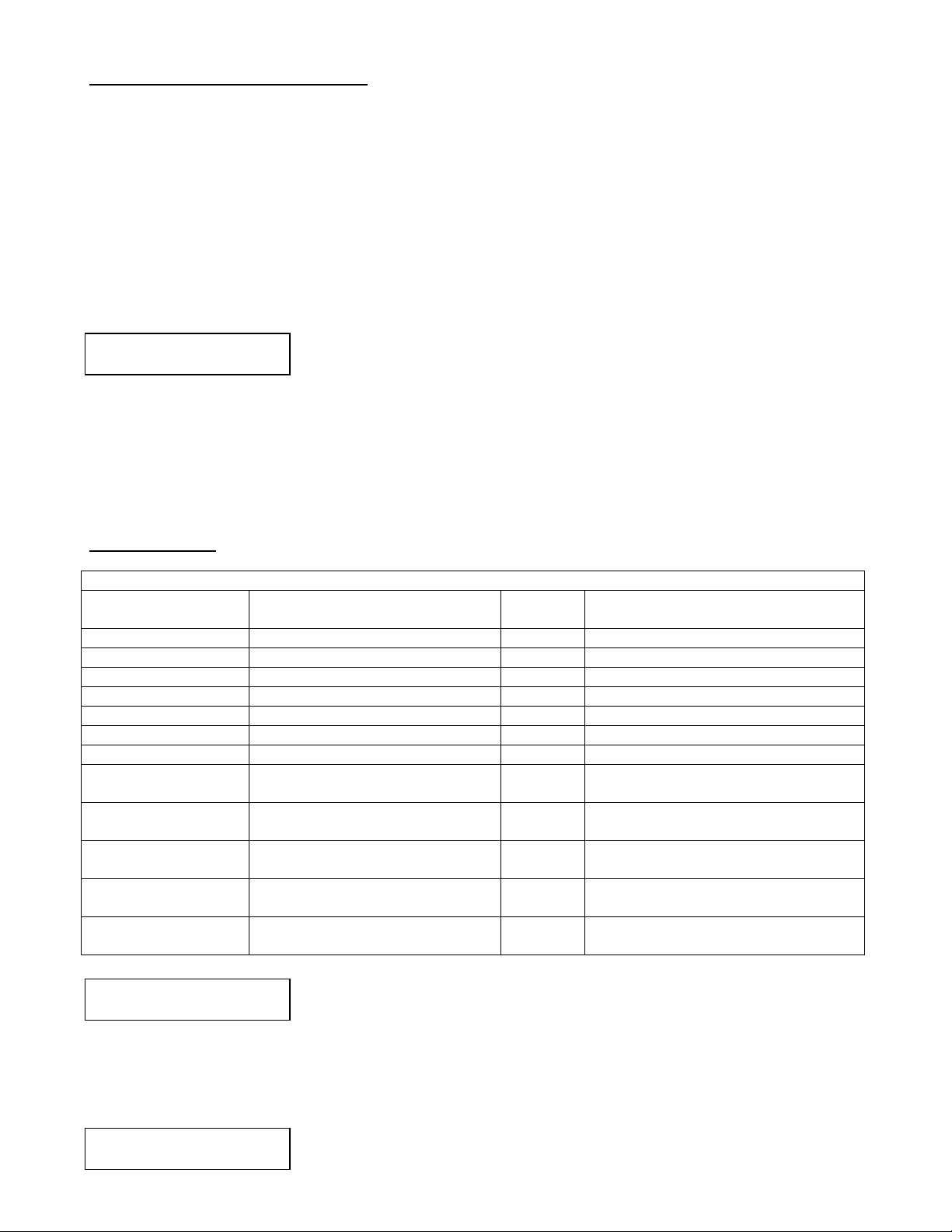
To connect keyboard to brewer loosen the 2 screws securing the keyboard cover plate on the left front
side of the brewers upper wrapper See Fig 2, Page 10. Access plate will swivel away from opening. Carefully plug
keyboard into the exposed port. Note orientation of connector in relation to port to avoid misalignment. Do not
force plug into port.
To enter the custom message programming mode press the 'Esc' key. Custom message programing
requires a password be entered for any functions. When prompted, enter the password. The factory set password
is "java". If the password has been changed enter the new password. Note: the brewer software is not case
sensitive. A window similar to the following will appear.
This message will display for 5 seconds and an audible signal will sound to alert
the user that the brew cycle has been terminated prematurely when the cy cle is
cancelled before the total brew time has elapsed. The Time Remaining at the time
Select Message #01 E
Arrow Up/Dn, <E>nable
Edit Password:
JAVA
outlined beginning above to create or modify custom messages or message status
password written down in a safe and secure place.
Use the up arrow and down arrow to select the message you wish to create or modify. The message
number is represented above by #01, indicating message number 1. Modification may consist of entering a new
message, editing the content of an existing message, or activating/deactivating an existing message. Note:
Messages may not be erased but may be written over by other characters such as spaces and may be prevented
from displaying by deactivation. The 'E' in the display window after the message number indicates that the
message is enabled or active.
When the message number to be edited is displayed in the window press 'Enter' to view and/or edit the
message. Each message consist of 2 lines of 20 characters each. The following briefly describes the function of
certain keyboard keys for use in programing messages:
Home
- This will move the cursor to the beginning of the current line.
End
- This will move the cursor to the end of the current line.
Insert
- This will toggle between insert mode and type-over modes. In insert mode text is pushed to the right as
new characters are entered. Note: Characters pushed out of view on the display are erased. In type-over mode
text is overwritten as new text is typed. Insert mode is denoted by a flashing underline cursor and type-over mode
is indicated by a flashing character sized rectangular cursor.
To change the password press the F1 key at this screen. This puts you into the
edit password menu. To begin creating or modifying messages skip the next
paragraph.
Edit the password by typing over or deleting the password shown. When you are
satisfied with the changes, press the enter key and the new password will be
stored. You will also be returned to the ready/standby mode. Follow the steps
. Be sure to keep your
- 9 -
Page 10

Delete
- This will erase the character at the cursor position and pull all characters following to the left to fill its
space.
Backspace
the right) to the left to fill the deleted characters space.
Arrow Keys
automatically wrap to the next line. Use the arrow keys to move between lines. Also note that to center a message
in the display it is best to type in the complete message first and then move to the beginning of the message lines
and move the text by inserting or deleting spaces in front of the text until the desired effect is achieved. The
backspace key will drag line content from the current cursor position and to the right to the left. Characters on the
left will be deleted as the text or blank spaces are drug over it. Once the message is satisfactory press 'Enter' to
store the message.
the message has been enabled. Only enabled messages will be displayed when exiting the custom message
programming mode. Other messages are retained in memory for later display however.
message will display as appropriate and may be modified as outlined above.
1 minute the brewer will return to normal operation mode. While modifying a message, before pressing 'Enter', if
you wish to restore the message to its premodified content simply press 'Esc' to exit the message. When reentering the message it will appear as before. Once all messages have been modified and enabled as desired
press 'Esc' to exit the custom message programming mode and return the brewer to normal operation. If message
have been enabled or disabled and there is no keyboard activity for a period of 1 minute the brewer will return to
normal operation mode and changes to message status will be in effect.
- This will erase the character to the left of the cursor while moving all characters (from the cursor to
- This will move the cursor in the respected direction (left, right, up or down).
Note that if you continue to type when the cursor has reached the end of the line that the text will not
After storing the message press 'E' to enable the message. An E as noted on previous page indicates that
The custom service message, SRV, is located before message #01 and after Message #60. This
If at anytime during the programming process outlined above, there is no keyboard activity for a period of
When the brewer is idle it will initially display "Ready to Brew". The brewer will then cycle through all
messages which have been enabled displaying each for approximately 5 seconds before scrolling off the display
while the next message scrolls on to it. After completing the display of all selected messages the process will
begin again with "Ready to Brew".
Figure 2 - Keyboard and Keyboard Port Access
- 10 -
Page 11

Page 12

 Loading...