

Page 1

Brewer
Brewer
OPERATOR’S HANDBOOK
Page 2
This handbook contains instructions for the GEVALIA Brewer .
Please read the handbook before using the machine.
OPERATOR’S HANDBOOK
Keep this fold out page open while reading the Operator’s Handbook.
Page 3
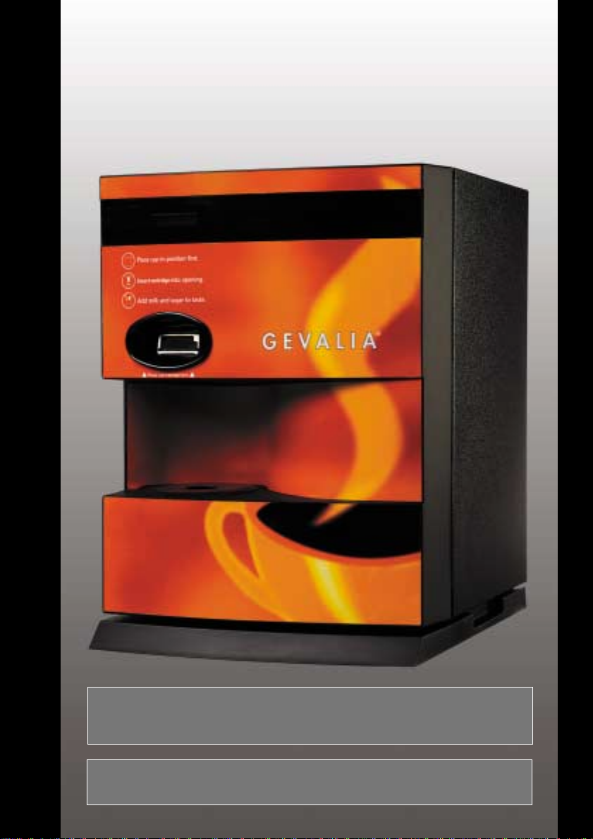
Machine Layout
Display
Capsule
Entry Slot
External Features
Power Cord
Cup Fill
Position
Door
Program
Button
Reset Button
Brew Mechanism
Release Catch (see
page 8 for detail)
W ater Inlet
Fitting
Internal Features With Door Open
Over-Temperature
Reset Button
Filling Funnel
Capsule Entry Flap
Tank Drain T ube
Capsule Bin
Spill Sensor
(Behind Capsule Bin)
Tank Overflow Tube
Page 4
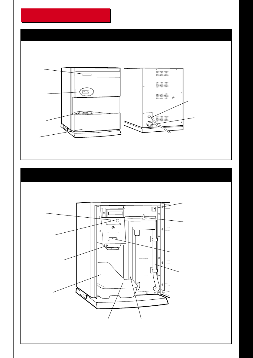
Technical Details
18.3in / 465mm
1.9in / 50mm
16.9in / 430mm
Dimensions
13.8in / 350mm
ELECTRICAL POWER SUPPL Y
The machine operates from a 120 V 50-60 Hz
single phase A.C. power supply.
POWER RA TING
The machine is rated at 1.3 kW for Canada and
either 1.3 kW or 1.6 kW for US only. Current
drawn is approximately 10.8 and 13.3 A
respectively.
W A TER SUPPLY OPTIONS
PLUMBED
1) Flush water line prior to brewer installation.
Connect to a cold water line.
2) W ater pressure should be at least 20 psi. For
less than 25' run, use 1/4" copper tubing and
connect to 1/2" or larger water line. For longer
runs, use 3/8" copper tubing and connect to
1/2" or larger water line and provide an
adaptor fitting for connection to the brewer.
3) If installed with a saddle valve the port should
have a minimum of 1/8" port hole for up to
25' run and 5/16" port hole for over 25' run.
4) Connect water line to plumbing fitting
extending from the rear of the brewer.
MANUAL FILL
Jug Fill - the machine may be filled manually
by opening the front cover to expose the filling
funnel. The tank has an average working
capacity of 30 cups between refills.
CAPSULE BIN CAP ACITY
The capsule bin will hold up to thirty capsules.
Capacity can be increased by mounting the
machine on a base cabinet with built in trash
bin.
WEIGHT
Filled with water: 53 lbs / 24kg.
Empty: 40 lbs / 18kg.
CAUTION: This machine should not be
used with artificially softened water.
Page 5

Do Not Print
Do Not Print
This
This
Page
Page
OPERATOR’S HANDBOOK
Page 6

Contents
Machine Layout Inside Front Cover
Technical Details Inside Front Cover
Important Safeguards 3
Setting Up 4
How to Get a Drink 6
Daily Maintenance 7
Weekly Maintenance 8
Adjusting Drinks Volume 10
Drinks Counter 1 0
What T o Do If Things Go Wrong 11
Display Messages 1 2
Customer Service 1 6
OPERATOR’S HANDBOOK
1
Page 7

OPERATOR’S HANDBOOK
2
Part No. 792440/1
Page 8

Important Safeguards
When using your Brewer, always follow these basic safety precautions:
1. Read all instructions before using the machine, and ensure that anyone who will
be involved with the cleaning or refilling of the machine also reads the
instructions.
2. This machine may contain up to 1-1/3 gallons of very hot water (up to 205° F).
Therefore, supervision should always be available when the machine is being
used near young children, the aged, or the infirm.
3. The machine should be situated on a strong horizontal surface, at a convenient
height, in a position where it is not likely to be knocked off.
4. The Power Cord should never trail from the machine, and should always be kept
away from hot surfaces and sharp edges.
5. Do not operate the machine if any part is damaged, e.g. Power Cord, until it has
been checked by a qualified Technical Service Representative.
6. Allow the machine to cool before handling or moving.
7. Never immerse the machine in water, or any other liquid, and never clean with a
water jet.
8. If the machine should accidentally freeze up, call a Technical Service
Representative to check it before switching on.
AL W A YS DISCONNECT THE MACHINE FROM THE ELECTRICAL POWER
SUPPL Y BEFORE CLEANING AND SER VICING.
OPERATOR’S HANDBOOK
3
Page 9

Setting Up
Plumbed In Fill Option
Ensure water connection is made and
water is turned on.
Press and hold the Program button, and at
the same time, plug the power cord into
the wall socket.
Machine will display
Release Program button and press Reset
button to scroll through options (which
alternate between Plumbed and Manual)
until the display reads
Press and release Program button to return
to normal operation. Water will fill into
machine until display reads
After a delay of approximately 15-20
minutes, the display will show 'Ready' and
the machine can be used.
OPERATOR’S HANDBOOK
4
or
Page 10

Manual Fill Option
Press and hold Program button and, at the
same time, plug the power cord into the
wall socket.
Machine will display
Release Program button and press Reset
button to scroll through options (which
alternate between Plumbed and Manual)
until the display reads
(i.e. filled by hand into the fill funnel)
Press and release the Program button to
return to normal operation.
When display shows
Pour water into funnel, as shown, until
water is level with the 'full' mark on the
side of the fill funnel.
Display will then show
After a delay of approximately 15-20
minutes, the display will show 'Ready' and
the machine can be used.
or
OPERATOR’S HANDBOOK
5
Page 11

How To Get A Drink
1. Place a cup in the correct
position on the cup grille.
2. Hold capsule as shown, label side
up.
3. Insert capsule, pointed end first,
fully into the slot above the cup
station.
The capsule will be automatically
drawn into the machine, and will
commence brewing.
4. The drink will now be delivered
into the cup. The capsule will
be disposed of automatically.
Add milk and sugar as required.
OPERATOR’S HANDBOOK
6
Page 12

Daily Maintenance
Emptying The Capsule Bin
The capsule bin holds thirty capsules, and should, therefore, be emptied and cleaned daily. If the
bin becomes full, the machine's display will read:
The capsule bin is full. Open the front door, remove the bin (fig i), and dispose of the contents.
Replace bin, after washing in warm water. If 'Check Bin' message persists, switch off the machine
and check underneath the brew mechanism to ensure a capsule is not still trapped. Remove the
offending capsule, close the front door, switch on
the machine and it will reset automatically.
NOTE: This automatic warning feature will not
normally work on the optional base cabinet with
the bin inside the cabinet; this must be checked
daily by the key operator.
fig. i
Pull
Cleaning The Cup Station
Remove the cup stand and drip tray (fig. ii), and wash in warm, soapy water before replacing.
Ensure it is correctly located.
fig. ii
Cup Stand
Drip tray
OPERATOR’S HANDBOOK
7
Page 13

Weekly Maintenance
Cleaning The Clamp Assembly
WARNING: ALWAYS DISCONNECT THE MACHINE FROM THE ELECTRICAL
SUPPLY BEFORE CARRYING OUT THIS OPERATION.
For weekly cleaning, or in the unlikely event of a capsule jamming, switch off the machine, open
the door and remove the capsule bin, and lower the clamp assembly as follows:-
Place your thumb on the front cover of the
brew mechanism and your forefinger behind
the plastic latch. Unclip the latch by closing
your thumb and forefinger. Gently lower the
clamp plate assembly (fig. i).
CAUTION!! When the clamp plate
assembly is lowered, or removed, sharp
cutting teeth are exposed - handle with
care!
fig. i
With the clamp plate assembly lowered,
if you are clearing a jammed capsule,
you will now see whether a capsule is
2 - SLIDE FORWARDS
1 - LIFT
fig. ii
CAUTION!!
Sharp Edges
jammed inside. Carefully remove any
jammed capsules with your fingers - do
not use sharp instruments or tools in the
mechanism!
To unhook the clamp plate assembly,
firmly grasp it by the sides (fig. ii),
taking care not to touch the cutting
edges. Swing the clamp plate towards
you, to an angle of approximately 45°,
then lift and slide it towards you,
keeping it at the same angle.
OPERATOR’S HANDBOOK
8
Page 14

With the clamp plate assembly removed, the
clamp plate should be thoroughly cleaned,
paying particular attention to ensure that the
cutting teeth are clean.
A
fig. iii
If necessary the lower clamp plate can be split
to allow more thorough cleaning; simply push
in the two plastic lugs (fig. iii A) and the clamp
plate should unclip.
To re-assemble, push in the two plastic lugs
and snap the clamp plate back into position.
Whilst the clamp plate assembly is removed from the machine, look underneath the brewing
mechanism on the machine, and clean the underside of the brewing mechanism.
A
A
To replace the clamp plate assembly after
cleaning, look underneath the machine to
locate the hinge grooves (fig. iv A) either side
of the brewing mechanism. Holding the clamp
plate assembly in the palm of your hand, at
an angle of 45°, align the clamp plate hinges
(fig. iv B) with the hinge grooves and slide
the assembly backwards, whilst still holding
the clamp plate assembly at 45°, until it drops
on the hooks (fig. iv C). The clamp assembly
will swing freely if it is correctly located.
C
fig. iv
fig. v
B
Close the mechanism by placing your forefinger
behind the tab on the clamp plate assembly and
raising it upwards, towards you. With the clamp
plate in the 'up' position, place your thumb on the
latch and, whilst keeping your forefinger behind
the tab on the clamp plate assembly, snap the latch
shut (fig. v). Close the door and switch on the
machine.
OPERATOR’S HANDBOOK
9
Page 15

Adjusting Drinks Volume
If, for any reason, you wish to adjust the drinks
level, open the front door to gain access to the
program button:
Press and hold the program button for five
seconds.
Release the program button and the display will
show:
Press the reset button to increase the drinks level.
On reaching maximum, the levels will
automatically decrease in stages back to
minimum. Select the desired level, then press
the program button to return to operating mode.
!
W ater T emperature
Up T o 205°F / 96°C
Drinks Counter
Press the program and reset buttons together.
The display will remain for as long as you press
both buttons.
Release both buttons to return to normal
operation.
Note: The counter cannot be reset.
OPERATOR’S HANDBOOK
10
Page 16

What To Do If Things Go Wrong
In the unlikely event of a problem occurring, your machine will attempt to diagnose the fault and
display the appropriate message.
Try to identify the fault shown on the display with one of those illustrated on the following pages,
and follow the remedial course of action. Most of these problems can be solved by clearing the
cause of the fault, and pressing the reset button, or unplugging the machine from the electrical
outlet and then back in again after five seconds delay.
If, however, you require the assistance of a T echnical Service Representative, please help us to
help you by noting the cause of the problem and the circumstances under which it occurred. This
will help our Service Representative assess the situation more clearly.
OPERATOR’S HANDBOOK
11
Page 17

12
OPERATOR’S HANDBOOK
or
Display Messages
The machine is heating or filling the
water tank. This should take no more
than 15-20 minutes.
(manual fill machine only)
The capsule entry flap has locked
due to lack of water in the tank.
Refill the tank with water and the
machine will operate normally after
heating up the water.
The capsule bin is full.
NOTE: This automatic warning
feature will not work on machines
mounted on the optional base
cabinet. The bin inside the cabinet
must be checked daily by the key
operator.
Open the door, remove the capsule
bin, dispose of the contents, and
replace capsule bin.
If ‘CHECK BIN’ message persists,
switch off the machine and check
underneath the brew mechanism to
ensure a capsule is not still trapped
(see 'Cleaning the Clamp Assembly'
on page 8). Remove the offending
capsule, switch on the machine and
it will reset automatically .
Page 18

or
W ater or cof fee has leaked into the base
tray of the machine, either from the
capsule bin area or from the workings of
the machine itself.
Switch off the machine.
Open the door and remove the capsule
bin. Thoroughly dry the base tray using
absorbent paper towels. Pay particular
attention to the spill sensor, and dry it
thoroughly. Switch the machine on and it
will reset automatically.
If the fault recurs, and fresh clear water
is seen in the base tray area, disconnect
the machine from the power supply and
close the water tap.
Call a T echnical Service Representative.
There is a capsule in the entry flap
of the brew mechanism, or the
capsule entry flap is stuck open.
Remove the capsule from the entry
flap, or if the capsule entry flap is
stuck open, switch off the machine,
open the front door, and remove the
clamp assembly (see 'Cleaning the
Clamp Assembly' on page 8). Clear
away any obstacle holding the
capsule entry flap open and pull the
entry flap forward until it is in the
closed position. Reassemble the
clamp and close the door.
Switch on the machine to revert to
normal operation.
* may be any number from 1 - 9.
Switch off the machine, remove the
clamp, clear any jammed capsules
and replace the clamp.
Switch on the machine.
If the problem persists, call a
T echnical Service Representative.
13
OPERATOR’S HANDBOOK
Page 19

14
OPERATOR’S HANDBOOK
or or
Display Messages (cont.)
The lower plate of the brew mechanism
has been lowered or removed.
Switch off the machine.
Open the door, replace and close the
lower clamp plate.
Take care when handling the lower
plate as it has sharp cutting edges!
Switch on the machine.
An internal error has occurred.
Switch off the machine. After a delay of
5 seconds switch on again, this should
reset the machine.
If the problem recurs, call a Technical
Service Representative.
The machine has been trying to heat the
water for 20 minutes without success.
This suggests that the over-temperature
reset button has tripped, or the element
has failed.
Press the RED over-temperature reset
button situated on the top right hand side
panel, inside the main front door.
PRESS THE RESET BUTTON.
If the problem recurs after a further 20
minutes, SWITCH OFF THE
MACHINE, and call a Technical
Service Representative.
Page 20

or
or
(plumbed in machine only)
Ensure water supply is turned on.
Press the RESET button to return
machine to normal mode.
Pressure built up within the capsule while
brewing, the brewing cycle was stopped
and the capsule was ejected into the bin.
The customer may have received either
a short measure or possibly no drink at
all.
Switch off the machine and, after
following the instructions for ‘Cleaning the
Clamp Assembly’ (on page 8), close the
main door and switch on the machine.
If the fault recurs, call a Technical Service
Representative.
15
OPERATOR’S HANDBOOK
Page 21

Customer Service
Fault Rectification
Should you require the assistance of a Technical Service Representative, after
checking the ‘Display Messages’ (see Contents page), please contact the Newco
customer serice department at:
Telephone 800-325-7867
Fax 636-925-0029
Outside normal business hours, a telephone answering service is available.
If you wish to write to us, the address is:
Newco Enterprises, Inc.
1735 S. River Rd.
St. Charles, MO 63303 USA
OPERATOR’S HANDBOOK
16
Page 22

OPERATOR’S HANDBOOK
Page 23

OPERATOR’S HANDBOOK
 Loading...