

Page 1
DB2A INSTALLATION
REV 3-29-2006
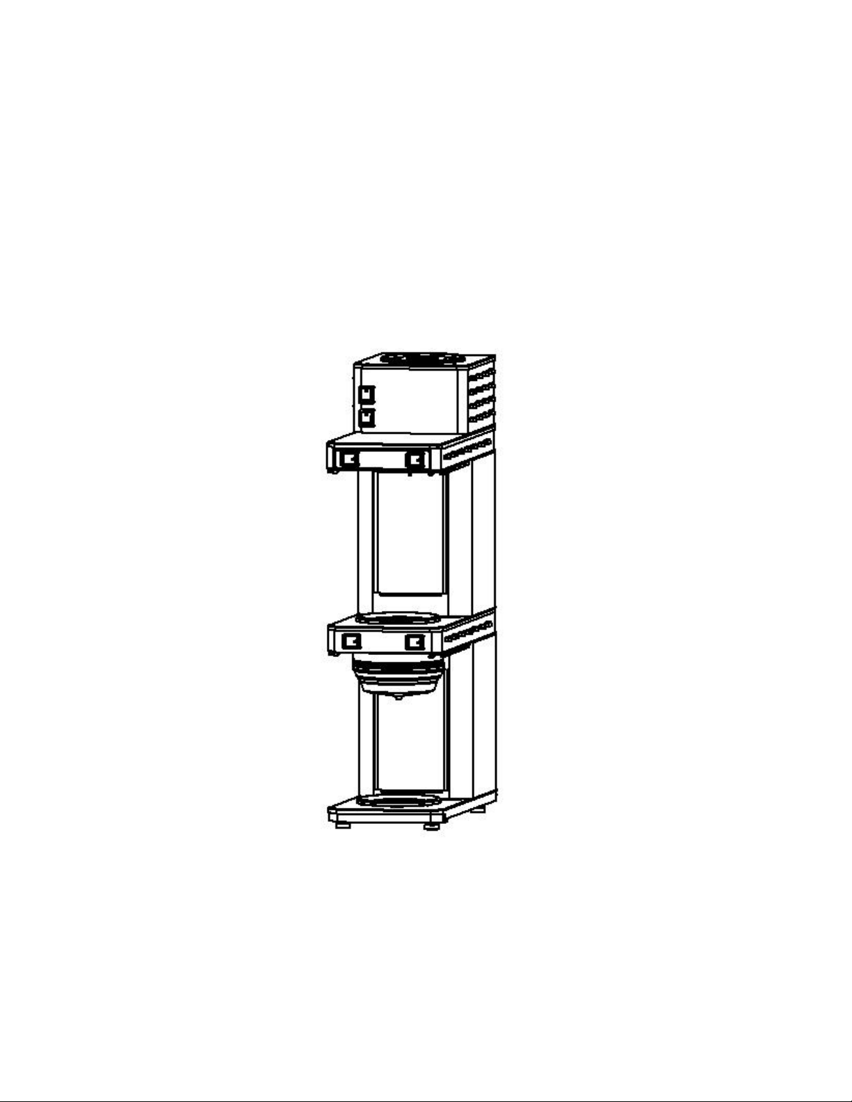
DUAL BREWER AUTOMATIC
DB2A
INSTALLATION, OPERATION, AND TROUBLESHOOTING MANUAL FOR
DB2A AUTOMATIC BREWER WITH WARMERS & POUR-OVER
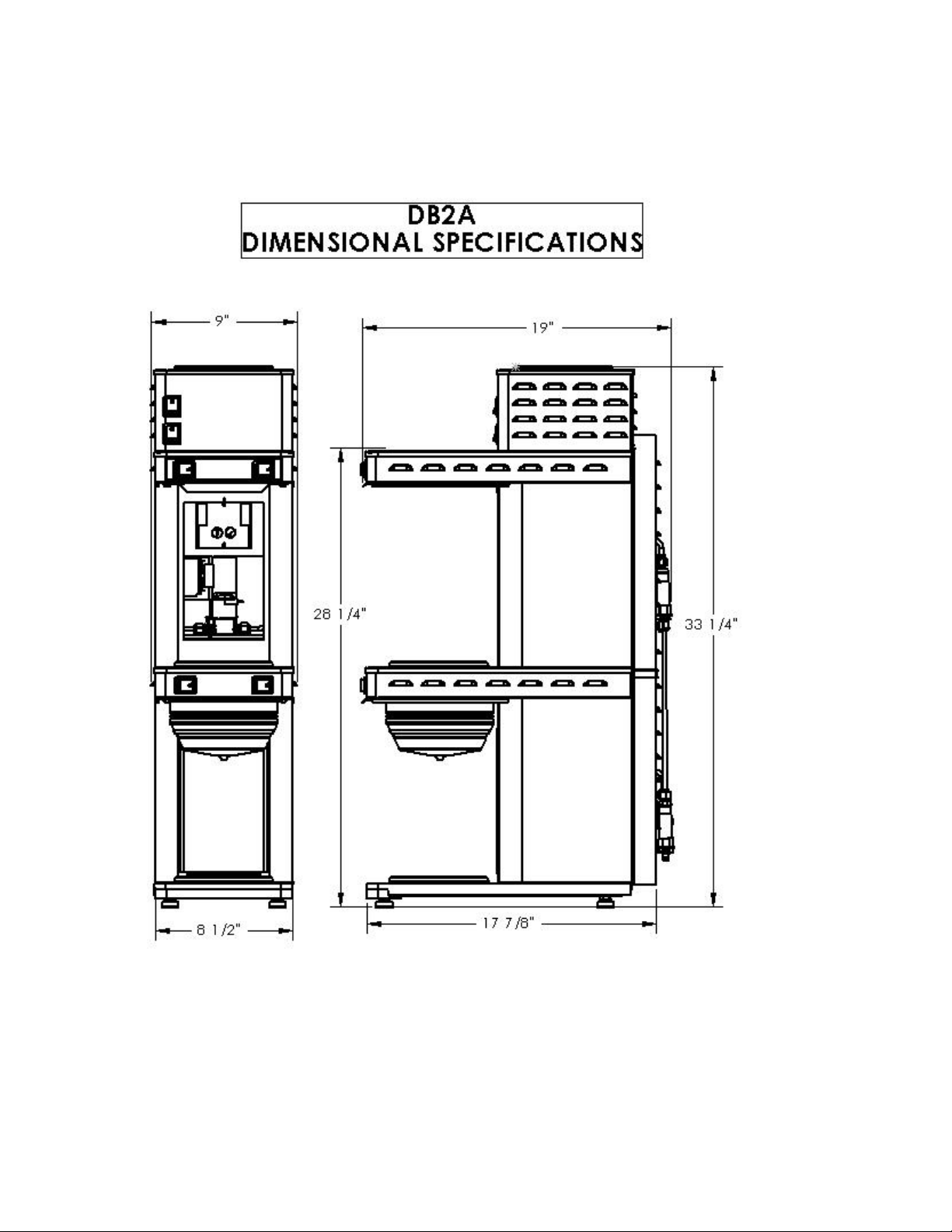
Model DB2A
8-1/2 W x 18 D x 33 H
4700 Total Watts, 23.3 AMPS
120/208 V
Ship Wt approx. 54 LB’s
Decanters Not Included
Page 2
2
Page 3
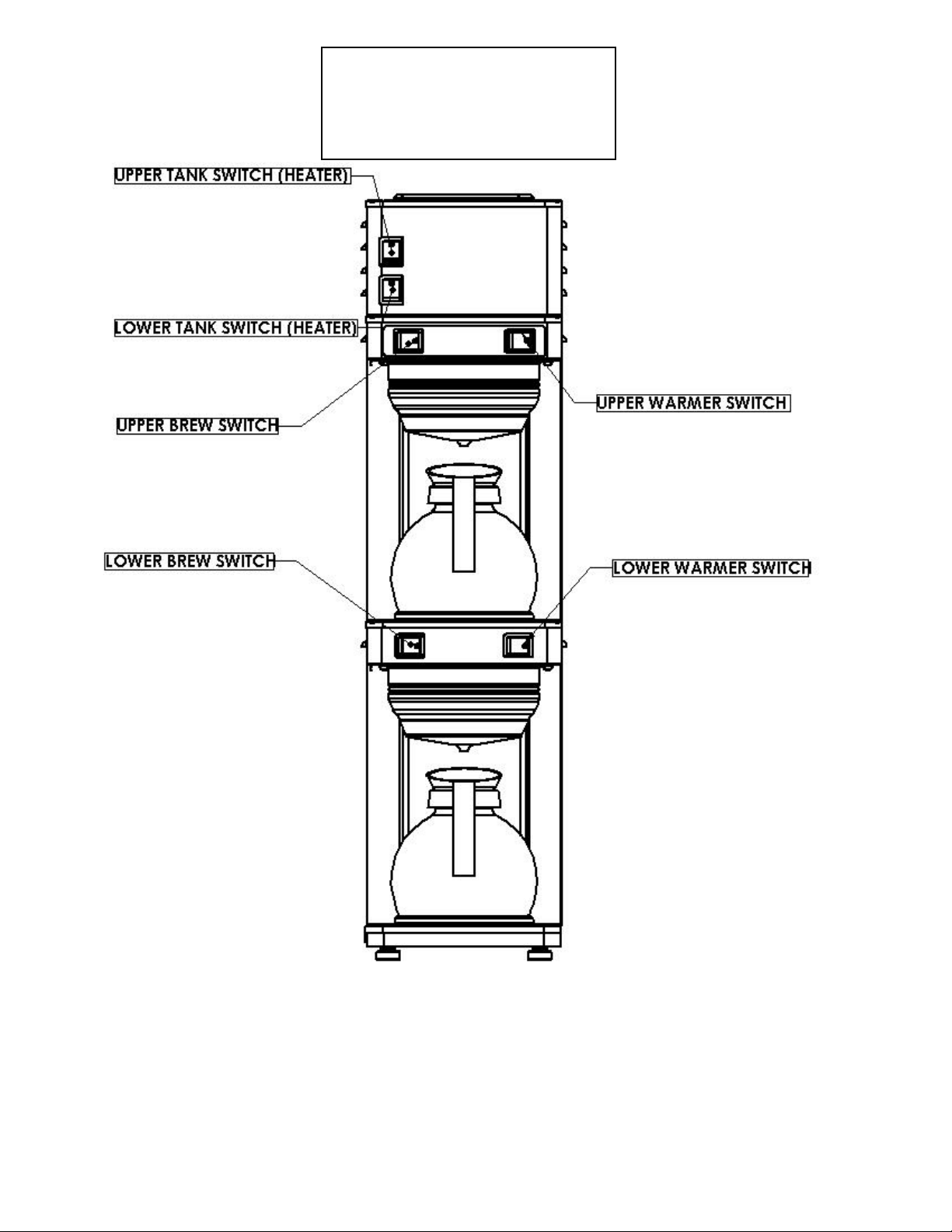
DB2A
CONTROL SWITCH
LOCATIONS
3
Page 4

PLUMBER'S INSTALLATION INSTRUCTIONS
CAUTION:Disconnect Power to brewer before proceeding with plumbing installation.
1) Attach water line to bottom PDS valve , rear of brewer .
2) Flush water line before installing brewer. Brewer should be connected to COLD WATER LINE for best operation.
3) Water pressure should be at least 40 lbs. For less than a 25 ft run, use 1/4" copper tubing and connect to 1/2" or larger water
line. For longer runs, use 3/8" copper tubing & connect to 1/2" or larger water line and provide an adapter fitting for
connection to the brewer. A dedicated water line is necessary for this machine.
4) If installed with saddle valve, the valve should have a minimum of 1/8" port hole for up to 25 ft run, and 5/16" port hole for
over 25 ft runs.
5) Manufacturer recommends connecting to copper tubing.
INSTALLATION INSTRUCTIONS
UPPER TANK SWITCH
WARNING: - Read and follow installation instructions before plugging or wiring in machine to electrical circuit. Warranty will be
dbvoid if machine is connected to any voltage other than that specified on the name plate.
FILL BREWER TANK WITH WATER BEFORE TURNING TANK THERMOSTATS OR HEATER SWITCHES ON !
1) Brewer is shipped with thermostat turned OFF, (full counter-clockwise position). Plug or wire in machine to appropriate
voltage as noted on the brewer serial tag. Serial tag is located on side of brewer.
2) Adjust timer to deliver desired amount of water (Timer is located behind front access panel). To brew into a regular 64 oz.
decanter little adjustment should be needed. Turn timer dial clockwise to increase volume of water, and counter clockwise to
decrease volume.
3) Place the decanters under brew baskets, turn on bottom two warmers, and using brew switches brew three brew cycles or
until water starts to drain into decanters.
4) Turn on tank heater switches. Allow 10 to 15 minutes for water in tank to heat to brewing temperature. (Additional water
may drip from brew baskets on initial expansion of water in the tanks). This will not occur thereafter.
5) After water has reached brewing temperature, thermostat will click off, heating noise will stop. Empty decanters and depress
brew start switches and run a cycle of water to remove expanded water from tanks. (Brew cycle may be canceled by turning
the warmer rocker switch back to the OFF position.)
6) Run one cycle for each tank to check for the proper temperature setting with an accurate thermometer. Take the temperature
of this water at a point below the brew basket opening, at the start of the brew cycle and when the decanter is half full.
Recommended temperature of the water is approximately 195 F. Adjust brew volume by adjusting the brew timer up or
down .
7) In higher altitude locations (5000 feet above sea level) the thermostat may have to be adjusted lower to prevent
boiling.
8) Water volume may need readjustment after brewing a decanter of coffee. (See next page)
4
Page 5

COFFEE PREPARATION PROCEDURES
1) Place filter into brew basket.
2) Put the proper amount of coffee into the filter.
3) Slide the brew basket into holder.
4) Place empty decanter on warmer located directly under the brew basket and turn corresponding warmer switch to ON
position.
5) Press “Brew” switch, switch will beep, and amber light will blink.
6) Hot water will be delivered through the sprayhead. This distributes the hot water evenly over the coffee bed within the brew
basket. The coffee brew will drain from the brew basket into the decanter below.
7) The resultant coffee brew should be crystal clear and have the desired properties attainable through excellent extraction.
8) TURN OFF WARMER WHEN NOT IN USE. (Red light indicates warmer is on.)
9) To clean brew basket simply remove from brew rails and dump filter into waste basket. The brewing process, as described
above, can now be started again.
DELIMING
To prevent liming problems in tank fittings remove sprayhead and insert deliming spring all the way into the tank. When
inserted into tank properly, no more than ten inches of the spring should be visible at the sprayhead fitting. Saw back and forth five or
six times. This will keep fittings open and clear of lime. In hard water areas this should be done everyday. This process takes
approximately one minute. In all areas the sprayhead should be cleaned at least once a week. Where bad liming has already occurred,
a new complete tank assembly may be installed. Deliming spring will not go in overflow orifice. (see diagram below)
Sprayhead
outlet
DELIMING SPRING PN 120127 (INCLUDED)
WARRANTY
Refer to Warranty Agreement between TDL Group, BBC Sales, and Newco Enterprises.
Overflow
orifice
5
Page 6

TROUBLE SHOOTING GUIDE
SYMPTOM POSSIBLE
CAUSE
CAN'T START BREW CYCLE
NO HOT WATER
DRIPPING
STEAMING OR SPITTING
AROUND FUNNEL
WATER KEEPS RUNNING
1. No water.
2. No power.
3. Warmer switch not on
4. Brew start switch.
5. Timer or timer harness.
6. Solenoid valve.
1. Tank heater.
2. Hi-limit thermostat or main
thermostat.
1. Not siphoning properly.
2. Solenoid valve not seating
properly.
1. Main thermostat.
2. High altitude.
1. Solenoid valve.
2. Start switch.
3. Timer
WHAT TO
CHECK
1. Incoming water lines & water shut
off valve.
2. Fuse or circuit breaker.
Power cord and plug connections.
3. Switch is on and lighted red,
continuity
4. Switch continuity.
(Normally closed.)
5. Wire leads to solenoid and
white 3-pin connector.
6. (A) Voltage at solenoid valve
terminals. Start a brew cycle and
check for 120 volts AC.
(B) If voltage is present at
terminals, check for water at line
pressure on the inlet side of
solenoid valve.
1. Check the voltage at the tank
heater terminals. Voltage should be
as indicated on the serial tag (on
rear of brewer.)
2. Check the voltage between the
VIOLET/RED wire on the tank
element and the incoming terminal
(VIOLET/BLACK) on tthe hi-limit
thermostat, then the outgoing
terminal (VIOLET/BLACK) on the
hi-limit thermostat.
1. Water should flow freely from the
sprayhead.
2. Solenoid valve assembly .
1. Thermostat points stuc k or out of
calibration.
2. Located above 5,000 feet.
1. Refer to "DRIPPING", Step 1.
2. Remove wires from switch an d
check continuity.
3. Solid state timers are not
repairable. If timer will not shut
off, replace timer.
REMEDY
1. Be sure water shut off is open.
2. Replace or reset circuit protector
3. If warmer switch does not make and
break contact, replace warmer switch.
4. If brew start switch does not make and
break contact, replace brew start switch.
5. Make sure these connections are tight. If
so, and all else checks out OK, replace
timer.
6. (A) If voltage is not present at terminals,
refer to steps 2 through 5.
(B) If voltage is present at terminals and
water at line pressure is present on the
inlet side of the solenoid, but not present
on the outgoing side, replace solenoid.
1. (A) If correct voltage is present at the
tank heater terminals and water in tank is
not being heated, replace the tank heater.
(B) If voltage is not present at the tank
heater terminals refer, to step 2.
(C) If incorrect voltage is present at the
tank heater terminals, check voltage at
outlet.
2. (A) If voltage is present on the incoming
terminal of the hi-limit t hermostat, but
not on the outgoing terminal, replace the
hi-limit thermostat.
(B) Check voltage at the terminal blocks.
If voltage is not present check outlet or
circuit breaker.
(C) If voltage is not present on the
incoming terminal of the hi-l imit
thermostat, replace the main thermostat.
1. (A) Clean sprayhead holes.
(B) Check tightness of sprayhead tube.
(C) See "DELIMING" , Page 5.
2. Be sure spring is in place and any
particles are cleaned from valve seat. If
valve seat is worn or mutilated, replace
solenoid valve.
1. (A) Adjust thermostat.
(B) Thermostat should be calibrated or
replaced.
2. See "INSTALLATION
INSTRUCTIONS", Page 4..
1. Refer to "DRIPPING", Step 1.
2. If start switch does not m a ke and break
contact, switch should be replaced.
3. Replace timer.
6
Page 7

TROUBLE SHOOTING GUIDE
SYMPTOM POSSIBLE
CAUSE
IRREGULAR YIELD
DRY COFFEE REMAINING
IN BREW BASKET AFTER
BREWING
WEAK COFFEE
SOLENOID CHATTER OR
HOWLING
COLD WARMER STATION
1. Not siphoning properly.
2. Timer.
3. Fluctuating water pressure.
4. Solenoid valve.
5. PDS valve
1. Filters.
2. Not siphoning properly.
3. Improper loading of the brew
basket.
1. Filters.
2. Not siphoning properly.
3. Improper loading of brew basket.
1. Brewer connected to hot water
line.
2. Vibration.
3. High water pressure.
4. Water hammer.
5. 60 cycle vibration.
1. Warmer - defective.
2. Warmer ON/OFF Switch.
3. Bad harness.
WHAT TO
CHECK
1. Refer to "DRIPPING", Step 1.
2. Timer consistency. Time several
brew cycles.
3. Water pressure.
4. Refer to "DRIPPING", Step 2.
5. Possible defective flow
control.
1. Are correct filters being used.
2. Refer to "DRIPPING", Step 1.
3. Filter and coffee in brew basket.
1. Are correct filters being used.
2. Refer to "DRIPPING", Step 1.
3. Filter and coffee in brew basket.
1. Incoming water line.
2. If brewer is on a metal stand or
counter, neither the bottom pan
nor copper tubing to the brewer
should touch the counter.
3. Water pressure on incoming line.
4. Incoming plumbing.
5. Nut on top of solenoid.
1. Voltage at warmer terminals
should be 120 volts AC.
2. If voltage is not present on warmer
terminals, check continuity of
switch.
3. Check connections betwe e n
harness and switch, and betw een
switch and warmer.
REMEDY
1. Refer to "DRIPPING", Step 1.
2. If times are irregular, replace timer.
3. If pressure fluctuates 10-20 PSI d uring
operation of brew cycle, add a pressure
regulator to inlet side of brewer , set to
lowest pressure level registered. Adjust
timer to yield correct water level.
4. Refer to "DRIPPING", Step 2.
5. Replace PDS valve
.
1. Insert correct filter.
2. Refer to "DRIPPING", Step 1.
3. Filter should be centered in the brew
basket and coffee bed should be le vel.
1. Insert correct filter.
2. Refer to "DRIPPING", Step 1.
3. Filter should be centered in brew basket
and coffee bed should be level.
1. Brewer should be connected to cold
water line.
2. Adjust as necessary.
3. If water pressure is over 90 PSI install a
pressure regulator and adjust to 50 PSI.
4. This is not the fault of the brewer an d can
usually be corrected by rearranging some
plumbing or adding an air chamber to
the incoming water line.
5. Nut should be tight. Tighten as required.
1. If voltage is present on terminals, but
warmer will not heat, replace w a rmer.
2. If switch does not make and brea k
continuity when turned off, replace
switch.
3. All connections should be tight.
7
Page 8

DB2A
ACCESS
PANEL
COMPONENTS
8
Page 9

REPLACEMENT
PART DIAGRAM
FRONT VIEW
9
Page 10

REPLACEMENT
PART DIAGRAM
REAR VIEW
55
34
4
54
47
33
1
32
3
10
Page 11

REPLACEMENT
PART DIAGRAM
WATER TANKS
5
120079
UPPER TANK ASS'Y
74
27
22
41
120069
LOWER TANK ASS'Y
36
42
23
39
58
11
Page 12

PARTS LISTING
* NOT SHOWN IN DIAGRAMS
PART
ITEM #
# DESCRIPTION ITEM # PART # DESCRIPTION
1 100250 VALVE,SOLENOID (SKINNER) 38 100043 KNOB,THERMOSTAT (102299)
2 110190 BREW TIMER 39 120071 SPHD TUBE ASY,LOWER,DB3A
3 110304 PDS VALVE, LOWER TANK 40 120075 TUBE ASSY,VENT,DB3A
4 110305 PDS VALVE, UPPER TANK 41
5 120048 PAN,REC,PUNCHED,DB3A 42 120106 SPHD TUBE ASY,UPPER,DB3A
6 120049 BASE ASSY,DB3A 43 120109 TERMINAL BLOCK SCREW/TAB
7 100010 PLATE,WARM ASSY BLK 44 120089 TUBE ASSY, FILL
8 111377 FOOT,APPLIANCE,3/8-16 X 1 45 120153 BASKET, SS, SMALL, FRENCH LBL
9 111667 NUT,3/8-16 JAM,ZPS 46 120088 TUBE ASSY,SOLENOID,DB3A
10 120050 BASE BOTTOM,DB3A 47 120090 TUBE ASSY,PDS TO PDS,DB3A
11 120051 BASE TOP,DB3A 48 120092 HARN,UPPER WARMER,DB3A *
12 120052 COLUMN,LOWER,DB3A 49 120093 HARN,POWER,LOWER,DB3A *
13 120053 PLATE,ACCESS,DB3A 50 120094 HARN,POWER,UPPER,DB3A *
14 120109 BLOCK,TERMINAL SCREW TAB 51 120095 HARN,MAIN,UPPER,DB3A *
15 120055 PLATE,BREW,SPTWLD,DB3A 52 120096 HARN,MAIN,LOWER,DB3A *
16 120057 RAIL,BREW,LH,DB3A 53 120097 BRACKET,SOLENOID,DB3A
17 120058 RAIL,BREW,RH,DB3A 54 120098 BRACKET,LOWER,INLET,DB3A
18 120059 WRAPPER,SPTWLD,DB3A 55 120099 BRACKET,UPPER,INLET,DB3A
19 120091 HARN,WARM&TIMER SWI,DB3A 56 151590 CORD ASY,240V,30A,CM BAR *
20 781431
21 781870 SWITCH. TANK POWER, GREEN
22 704221 GASKET,TANK SILICONE 59
23 704119 TANK,ONLY,K-STYLE 60
24 120061 BASE/COVER,TOP,DB3A 61
25 120062 COLUMN,MIDDLE,DB3A 62
26 120114 COLUMN,UPPER,DB2A 63
27 111593 THERMO,MAN,RESET,R/AG/TAB 64
28 100015 DISH, POUR-IN ASSY S/S 65 781432 SWITCH, WARMER, RED
29 100019 PLATE, POUR-IN S/S 66
30
100180-1
31 120065 COVER,DB3A 68
32 120066 PANEL,LOWER BACK,DB3A 69
33 120067 PANEL,MIDDLE BACK 70
34 120068 PANEL,UPPER BACK,DB3A 71
35 120085 BRACKET,COMPONENT,DB3A 72
36 100025 GASKET,SPRAYHEAD 73
37 107134
SWITCH,BREWER START- AMBER
58
COVER,ASSY W/CHAIN BLK 67
THERMOSTAT,SUN ASY ,201
74 1
120126-10
57 201128 VALVE, SHUTOFF 1/4 FLARE
120075 TUBE, ASS’Y, VENT, LOWER TANK
201991
120127
100187
100008
120079
120069
101429
100065
100160
110666
100055
100613
511027
781544
20146
ELEMENT MAIN 3000/2250W 240/208V
SOLENOID VALVE REPAIR KIT*
DELIMING SPRING (WITH BALL)*
WARMER ELEMENT*
WARMER PLATE*
UPPER TANK ASS'Y
LOWER TANK ASS'Y
#6 COMBO HD SCREW-COVERS*
#6-32 SCREW-BREW RAILS.*
SCREW, 4-40 X 5/8- WARMER PLATE*
SCREW, 6-32, THERMOSTAT MTG*
SCREW, 4-40 X 3/8, POUR-IN CVR*
10-32 SCREW, SOLENOID MTG.*
SCREW, 8-32 X 3/8, BODY & BRKT*
SCREW, 8-32 X 1/2, TERM BLK MTG*
OVERFLOW TUBE ASS’Y
12
Page 13

DBA2 WIRING DIAGRAM
UPPER ELEMENT
1
1
2
2
3
3
WH
LOWER ELEMENT
1
WH
2
3
BK
4
4
5
5
6
6
BK
4
5
6
BK
VI O
BK
BK
VI O
BK
UPPER TANK
ELEM
LOWER TANK
ELEM
VIO
BK
VIO
BK
VI O
RD
HI-LIMIT
REGULATING
THERMOSTAT
VI O
RD
HI-LIMIT
REGULATING
THERMOSTAT
VIO
BK
VI O
RD
VI O
RD
VI O
BK
MIDDLE WARMER
LOWER WARMER
BK
WH
1
2
3
1
2
3
WH
VI O
BK
WH
VI O
BK
BL
4
5
6
BK
4
5
6
WH
K
WHB
MIDDLE
WARMER
BK
VI O
RD
L1 L2 N E-L1
VI O
RD
WH
WH
BK
LOWER
WARMER
BK
VI O
RD
WH
RD
BK
UPPER BREW
1
2
3
YEL
BK
WH
RD
BK
LOWER BREW
1
2
3
YEL
BK
4
5
6
4
5
6
WH
RD
BK
WH
RD
BK
GREY
WH
VI O
BK
BK
GREY
WH
VI O
BK
VI O
BK
5
4
3
TIMER
2
1
1
2
3
4
5
6
BK
YEL
BK
FILL SOLENOID
BK
VI O
5
4
3
2
1
TIMER
1
2
3
4
5
6
BK
YEL
BK
FILL SOLENOID
GND
L1 L2 N E-L1
BK
GREEN
13
RED
LINE
BK
WH
 Loading...