

Page 1
Issued August 2013
INSTALLATION and OPERATION MANUAL
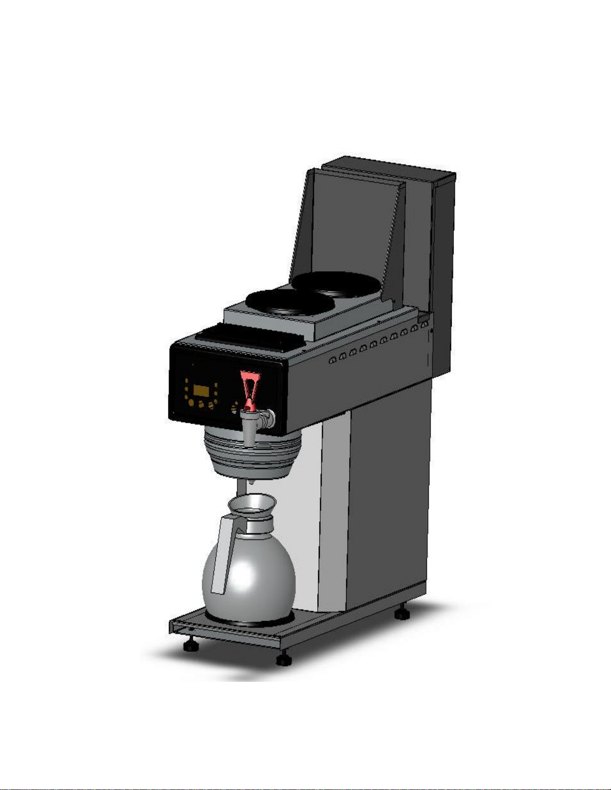
For MODEL AKPA-3 DB-T HW
TEA BREWER
& HOT WATER FAUCET MACHINE
1
Page 2

Issued August 2013
2
Page 3
A
n
r
Issued August 2013
KPA DB
Combi
H
ot Water/T
T-3 HW
ation
ea Brewe
3
Page 4
d
ASP
BEle
W
a
3
T
c
0
g
G
m
p
w
Issued Aug ust 2013
KPA DBT-
ECIFICA
HW
IONS
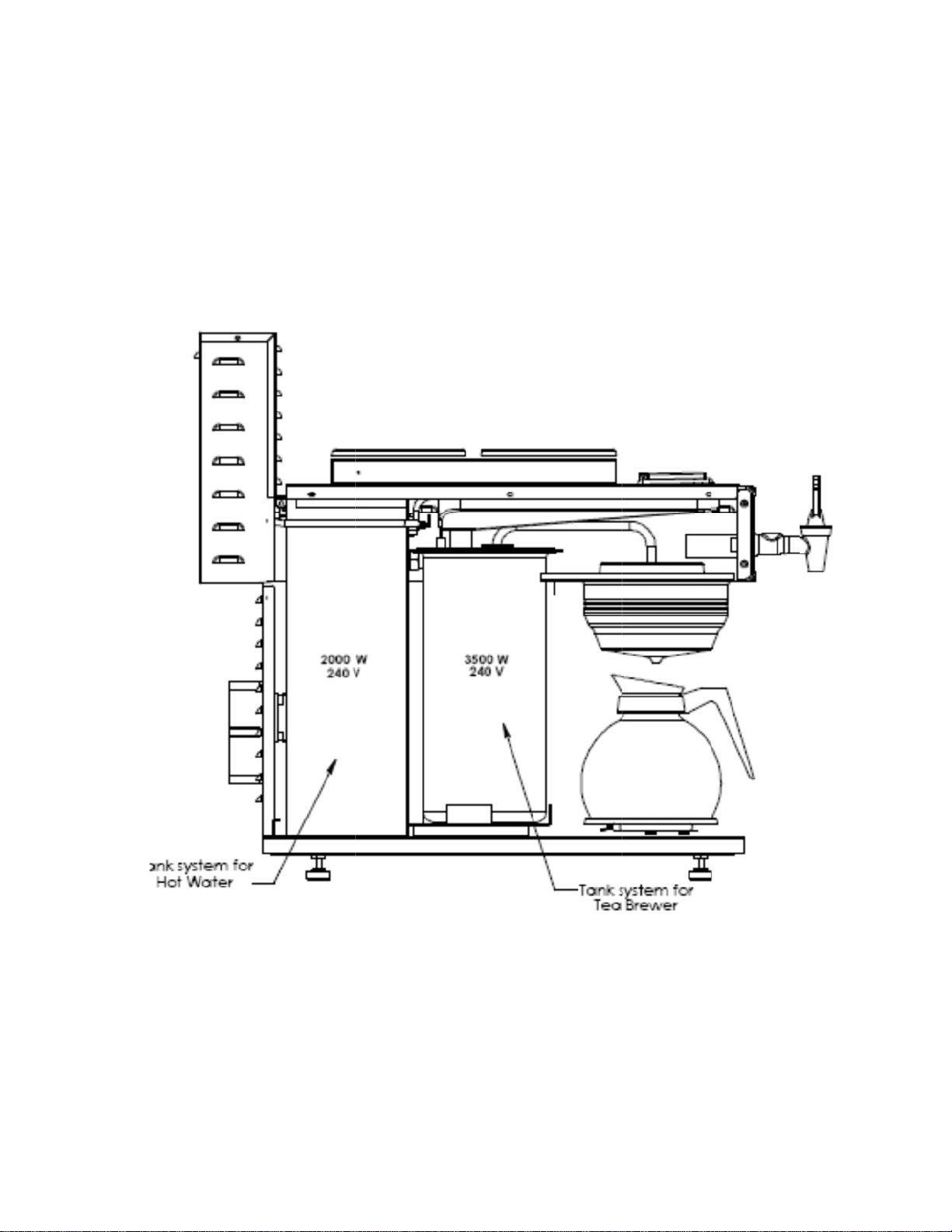
Indepen
Indep
240V 30
Hot Water
ent Hot
endent Te
rewer Spe
ctrical: 60
Amps Sin
Tank: 2.2
ater Syste
Brewer w
s:
0W
le Phase
allon Ca
with Po
ith Power
.
er Switch
Switch
4
Page 5
Issued August 2013
5
Page 6

Issued August 2013
BREWER SETUP
PLUMBER'S INSTALLATION INSTRUCTIONS
CAUTION:
1) Flush water line before installing brewer. Brewer should be connected to COLD WATER LINE for best operation.
2) Water pressure should be at least 20 lbs. For less than a 25 ft run, use 1/4" copper tubing and connect to 1/2" or larger
water line. For longer runs, use 3/8" copper tubing & connect to 1/2" or larger water line and provide an adapter fitting for
connection to the brewer.
3) If installed with saddle valve, the valve should have a minimum of 1/8" port hole for up to 25 ft run, and 5/16"
port hole for over 25 ft runs.
4) Connect incoming water line to the flow control device on the back of the brewer. A 1/4” flare fitting is provided.
Manufacturer recommends connecting to copper tubing.
ELECTRICAL HOOKUP
WARNING:
be void if machine is connected to any voltage other than that specified on the name plate.
The brewer has a power cord attached and is configured with a twist type plug, NEMA type L14-30. Brewer should be
connected to the appropriate receptacle type. A wiring diagram at the rear of this manual illustrates the complete brewer
wiring. Note that the tank heater system is the only portion of the brewer running on 240V. The balance of components is
powered by 120V obtained by tapping one leg, L1, of the circuit. An internal transformer provides low voltage power to the
control portion of the circuit.
- Read and follow installation instructions be fore plugging or wi ring in machine to electrica l circuit. Warranty will
INSTALLATION INSTRUCTIONS
WARNING:
1) Connect brewer to water line as described in “PLUMBER’S INSTALLATION INSTRUCTIONS”. Connect to suitable
power supply as described in “ELECTRICAL HOOKUP”. Turn power switch on for tea brewer and hot water machine, the
tanks will begin to f ill. The blue filtering light will indicate filling is in process. Time required to f ill the tanks is about 4-1/2
minutes. Fill times much shorter or longer than noted may indicate the PDS valve is out of calibration. The PDS valve is the
flow control device located on the rear of the machine and is factory set to the correct flow rate. See the “PDS VALVE
CALIBRATION” section for information on setting the proper flow control rate (tea machine).
Water levels in the tea brewer & hot water faucet tank are independently controlle d by level probes which sense whe n water
contact is made. A maximum run time of six minutes is programmed into the tea brewer for the initial fill cycle to prevent
flooding should an error occurs. Should the tea brewer call for water for a time period in excess of 6 minutes the brewer will
shut down the fill circuit and display an Er1 message. S ee the “E RROR MESSAGES” section for instructions on how to cl ear
the error and possible causes.
2) Once the water level has reached the proper water levels the tank heaters will begin to heat the water to the preset
temperatures. This prevents premature failure o f the element by heating it dry . This prob e will also call for p ower to be shut off
to the element should the water level fall below it (tea brewer). Heating time will be approximately10 minutes. The heating
circuit has a maximum continuou s run time of 30 min utes. Should the tea brew er call for heat for a time p eriod in excess of 30
minutes the brewer w ill shut down the h eating circuit a nd display an Er2 message. See the “E RROR MESSAGES” sectio n for
instructions on how to clear the error a nd possible causes. The heating light on the faceplate will indicate he ating status. As
the preset temperature is approached the light will begin pulsing as the power to the element is cycled on and off.
- Read and follow installation instructions before plugging or wiring in machine to electrical circuit.
Power to brewer must be OFF before proceeding with plumbing installation.
6
Page 7

3) Place a suitable container in place below the brew basket to catch water. Depress one of the brew start/stop switches. If
the brewer is up to temperature t he brew cycle will begin immediate ly , if not the brew er w ill go int o autoarm mode. In auto arm
mode the heating light will begin to flash but the fill portion of the brew cycle will not begin until the optimum (preset)
temperature has been reached. In higher altitude locations (5000 feet above se a level) the tank temperature may h ave t o b e
adjusted lower to prevent boiling. Compare the delivered volume to the programmed volume for the brew selected. Factory
settings are 30 oz for the half pot
of tea and 60 oz for th e f ull pot of t ea. If volume delivered varies substantially from the preset volume the PDS valve is out of
calibration. See the “PDS CALIBRATION” section for information on setting the proper flow control rate. See the
“PROGRAMMING” section for instructions on adjusting the preset tank temperature and brew volume(s).
Issued August 2013
TEA MACHINE OPERATION INSTRUCTIONS
TEA PREPARATION PROCEDURES
1) Place filter into brew basket.
2) Put the proper amount of tea into filter for volume to be brewed.
3) Slide the brew basket into holder above the lower warmer plate.
4) Place an empty carafe in place below the brew basket.
5) Press brew start/stop switch for brew volume desired.
A brew cy cle may be initiated even if the heating light is on. Read y light ind icates the tank has reached the preset temperature.
If the autoarm feature is enabled and the tank has not reached brewing temperature the heating light will begin to flash
indicating that the brewer is heating and will begin to brew immediately after the heating cycle is complete. Do not remove
decanter. Brew cycle may be canceled by depressing the brew start/stop switch. Heating light will cease flashing but may
remain on or may pulse if preset temperature has not been reached.
6) Hot water will be delivered thro ugh t he spra yhead. This distributes the hot water over the tea within the br ew basket. The
brewed tea will drain from the brew basket into the decanter below.
7) The LED display will co unt the brew ti me down unt il all the liquid has fin ished flow ing from the brew basket. Do not remo ve
decanter until the brewing process has stopped and all liquid has stopped flowing from the
brewbasket. See the “PROGRAMMING” section for instructions on adjusting the visibrew time. Visibrew is the time allowed
after the brew cycle for the hot tea to finish draining from the brewbasket.
8) After the brew cy cle has completed th e audible beep will sound and the brew basket icon will flash. Press t he quality b utton
to cancel the beep and to turn off brewbasket icon. To clean brew basket simply remove from brew rails and dump filter into
waste basket. Rinse basket if desired and replace in brewer. The brewing process, as described above, can now be started
again.
QUALITY CHECK
The quality check mode is used to display the programmed brew volume(s) in ounces, actual tank temperature and the total
number of brews for each side. To activate the display depress the quality check button. When the button is depressed the
display w ill show the pro grammed volume in ou nces th at brew one (TEA 1/2) is set for. Subs equent pre sses of the QUALITY
button will display brew volume for brew 2 (TEA 1), th e actual tank temperat ure and total number of brew s for brew 1 and brew
2. The selected item will display until beginning a brew cycle or pressing cancel.
7
Page 8

Issued August 2013
TEA BREWER FEATURE DESCRIPTIONS
The AKPA brewer incorporates the latest features in brewer contr ol technology. A lthough providing for enhan ced functionality
brewer controls remain intuitive a nd set up of key operating parameters couldn’t be easier. Multip le brew volumes, visa-brew
delay, tank tempe rature set point, br ew mode, filter p arameters and mor e are all set from the front cont rol panel using a digital
display for precise control. The Tim Horton brewers incorporate an additional program sequence, “Quality Check”, which
allows display of the programmed brew volume(s) in ounces, actual tank temperature and number of brews. The quality
information is displayed using a quality check button. The following pages will explain the control features and then step
through the process required to program your unit.
Brew Volume – The Digi Brew II series control has two independently programmable brew volumes denoted Tea
1/2 and Tea 1. Brew time is set by desired brew volume in ounces. Either of these brew times may be turne d off or set for any
volume from 30 ounces to 255 ounces for the ultimate in fle xibility . Selected brew volume is converted to br ew time inter nally
for calculations and to add to countdown time. PDS valve must be calibrated to deliver 1/4 gallon per minute in order to
ensure programmed brew volume is delivered.
Quality Check Mode
temperature and the total number of brew s for each side. To a ctivate the display depress the quality check button. When the
button is depressed the display will show the programmed volu me in o un ces t hat br ew one (T EA 1/ 2) is set for. Subsequent
presses of the QUALITY button will display brew volume for brew 2 (TEA 1), the actual tank temperature and total numb er of
brews for brew 1 and brew 2. The selected item will display until beginning a brew cycle or pressing cancel.
Visa-Brew Time – Provides for additional time to add to the programmed brew time. This additional time allows display to
continue countdown after the w ater delivery portion of brew cycl e to allow for the cof fee to finish draining from the br ew basket.
The digital countdown, and the delay in the audible coffee rea dy si gnal, aid in preventing premature removal of eith er the brew
basket or the dispenser.
Water Temperature Set Point – Allows for digitally setting the temperature of the water in the brewers tank system to any
value between 170 and 205 Deg F. Caution: Br ewer temperature is set at 203 de g and Hot Water Dispenser is set at 205 d eg.
In higher altitude locations, over 3500 feet a bove sea leve l, the te mperature will n eed to be a djusted down to prevent b oiling.
Auto Arm – When enabled this feature ensures that the brewer is up to temperature prior to brewing to ensure proper
extraction is obtained. If the water temperature in the tank is below the water temperature set point when the brew cycle is
initiated the water delivery portio n of the brew cy cle is d elay ed. The heating lig ht will begin to flash indicating that th e unit is in
the brew mode but is not up to temperature. At the same time the tank heater will begin heating and when the tank reaches
the preset temperature the brew cy cle w ill resume. Auto arm may be overri dden by pres sing and holding the appropriate b rew
button for several seconds until the brew cycle starts.
Pre-infusio n mod e – This mode delivers a small a mount of hot water over the coffee grounds and the n pauses to allow w etting
of the brewed product and to allow the product to absorb th e water before continui ng. After this pause the brew cycl e resumes
normally. Pre-infusio n can y ield better extraction rates than normal brewing modes. The pause time is added to the brew and
visa-brew time. The pre-infusion times are preset at the factory. Pre-infusion for Brew 1 and 2 may be turned on and off
independently.
Pulse Bre w M ode – This mode cy cles the fill valve o n and off during the brew cy cl e. This sl ows the entry of cold water into the
tank and minimiz es the mi xing action ca used by introducing a large volume of cold w ater into the tank at on e time resulting in
an increase in brew temperature. The additional turbulence and mixing created in the brew basket along with the increased
temperature can result in higher extraction rates for the coffee or tea. The time set for pulse brewing should exceed the time
required for brewing. The time difference between the pulse brew time and the brew time is the amount of time available as
off time. The difference is divided equally and distributed throu ghout the brew cy cle to pro vide a pulse after eve ry 3 0 seconds
of brewing. Pulse brew mode for Brew 1 and 2 may be turned on and off independently.
Audible Alert Mode – Provides an audible signal when tea has finished brewing notifying everybody that fresh tea is available.
May be turned off, set for 1-9 beeps or set to on for continuous beeping until cancel button is depressed. The empty basket
light will also flash to prompt operator to dump grounds from brew basket.
Brew Ready – Monitors the temperature of the water in the tank and lights when the programmed temperature has been
reached. If a brew cycle is started when the icon is not lit brew temperature may not be optimal if the autoarm feature,
described above, has been turned off.
–
The quality check mode is used to display the programmed brew volume(s) in ounces, actual tank
8
Page 9

Filtering Flow Rate – This is the flow rate of incoming w ater and is used to calcula te the volume of water that has been filte red.
The flow rates may be turned off or set for .25, .5 0, .75 o r 1.00 g allon per minu te (gpm) fl ow rates. The PDS valve on t he rear
of the unit should be calibrated to match the recommended flow rate of .25 gpm to properly display the brew volume in the
quality check mode and to deliver the programmed brew volume.
Filter Capacity – The filterin g capacity in gallons of the filter in stalled (optional) on the brew er may be selected here. Capacity
may be turned off or set for one of the following available values; 0, 500, 1500, 2000 or 2500 gallons.
Number of Brews – The number of brew cycles started ma y be tracked with this feature . T he accu mulate d n u mbe r of cycles
may be reset by using the brew buttons to display “Clr” when in the program mode and then depressing quality button. The
Quality check featu re will also display the nu mber of brews for both brew selections. The displa y is limited to 999 however the
control tracks up to 4000 brews internally. For each 1000 brew cycles completed a decimal point on the display is also
illuminated. Thus if 2 decimal points and 500 are display ed for TEA 1/2, there have been 2500 brew cy cles si nce the counter
was last reset.
Issued August 2013
Auto Warmer Shutoff – For warmer equipped units the control may be programmed to shut off the warmers after a
programmed period of time. The time interval may be set for any period of time up to 4hours and 15 minutes or the feature
may be turned off so that warmers operate manually.
Power Mode - allows y ou to automatically save energy when the brew er is not in use for a length of time specified under powe r
shutdown time. Available modes are normal, power save (standby) and power down. The modes are described below.
=
Normal - In this mode the tank temperature will be maintained at the preset temperature at all times.
=
Power Save (Standby) - In this mode the tank temperature will be maintained at approximately 170
degrees when the set time has been reached.
=
Power Down - In this mode the tank heater element will be disabled when the set time has been reached.
By depressing the brew start switch or if the brewer looses power the timer is reinitialized and the set time frame starts over.
In standby and power down modes the auto arm feature, if enabled, will bring the tank up to the preset temperature before
brewing when the brew switch is depressed.
Power Shutdown Time – This feature is used to set a specified length of time ranging from 30 to 240 minutes before the
standby or power down modes will take effect.
CONTROL PANEL LAYOUT
TEA Brewer Control Panel – Warmer Model
9
Page 10

(
Issued August 2013
PROGRAMMING
SEQUENCE OF PROGRAMMING STEPS FOR THE DIGI-BREW CONTROLLER
∗
Depress and hold QUALITY button until display lights up (Approx. 10 seconds).
∗
You are now in the Program Mode. Functions to be programmed appear in the order in which they are shown in the following
table.
∗
Use the QUALITY button to cycle through the functions to find the one you wish to change.
∗
Use the TEA1/2 button to lower the displayed value and the TEA 1 button to raise the value. Press QUALITY
button to store the changed value and advance to next function.
∗
If the Brewer detects no activity for approx. 60 seconds it will exit the Program Mode, except as noted below
CODE FUNCTION TO SET SET VALUE OPTIONS TEA BREWER
1A Brew 1 volume
1b Brew 2 volume (Right Button) OFF, 30 – 255 ounces 60 ounces
2 Visa-brew time OFF, 30 seconds – 2 ½ minutes 1:45
3 Water Temperature *1 170 °F – 205° F 203 Degrees F
4 Auto Arm ON or OFF On
5A Pre-infusion 1 mode ON or OFF Off
5b Pre-infusion 2 mode ON or OFF Off
6 Pulse brew mode ON or OFF On
6A Pulse brew 1 time *2 1:15
6b Pulse brew 2 time *3 3:15
7A Audible alert mode ON or OFF On
7b Audible alert no. of beeps ON,OFF, 1 – 9 On(Continuous)
9A Filtering flow rate OFF, 0.25 – 1.00 gal. / min .25 GPM
9b Filter capacity *4 OFF, 0.50 – 2.50 gal. X 100 2000 gallons
10 Number of Brews ON or OFF, Clr N/A
11A Auto Warmer Shutoff ON or OFF Off
11b Time Interval before shutoff 0-4:15 N/A
12A Power mode Normal, Power Save, Power Down Normal
12b Power shutdown time *5 30 minutes – 4 hours N/A
End None *6 N/A N/A
Left Button) OFF, 30–255 ounces 30 ounces
*1 Brewer will remain in this sequence indefinitely until CANCEL button is pressed.
*2 Hidden if pulse brew mode is OFF or brew 1 time is OFF.
*3 Hidden if pulse brew mode is OFF or brew 2 time is OFF.
*4 Hidden if filter flow rate is OFF.
*5 Hidden when power save mode is normal.
*6 Program mode will time out in 15 seconds at end of programming sequence.
.
ERROR MESSAGES
The following table explains the error messages which may be encountered on the brewer. The error messages may be cleared by going
into the program mode, using the brew buttons to display “Clr” and then pressing the cancel button.
ERRORMESSAGE DESCRIPTION CAUSE
Er1 Fill run error The fill solenoid has either run for more than six minutes on the initial tank fill or 3 minutes
in normal operation.
Er2 Heater run error The tank heater has run for more than 30 consecutive minutes.
Er3 Shorted probe Short in the thermistor circuit.
Er4 Open probe Break in the thermistor circuit.
Ful Filter limit reached The selected filtering capacity of the filter has been reached
10
Page 11

Issued August 2013
PDS VALVE CALIBRATION
The PDS valve is a flow control valve that is accurate over a wide range of water pressures and will maintain its volume setting
for many y ears w ithin the harsh w ater environ ment that commercial brew ing equipment mu st operate. The valve is adjustable
from 0.04 GPM to 0.31 GPM. Other features de signed into the valve in clude an internal w ater stra iner, an easy to adju st knob
for setting the flow rate, double O-ring swivel fi ttings to eliminate leak s due to equipment being moved, and a p orcelain sleev e
and piston assembly t hat is self cleaning and cannot be affected by chemicals within the wat er supply. The sy st em ha s been
designed to operate over a wide range of water pressures, from 10 PSI to 70 PSI with an accuracy of +/-1%. An additional
benefit of the PDS valve is reduced noise level over brewers equipped with conventional flow controls during the brewing
process.
The flow control setting of the PDS valve works in conjunction with the volume setting programmed into the brewer to
determine the volume of water being delivered during the brew cycle. For accurate brew volumes the flow control rate of the
PDS valve must be set to a rate of .25 gallons (32 ounces) per minute. This may be easily done by following one of the
procedures outlined below.
Method One – Off Brewer Calibration
1) Connect a water line which can be turned off and on to the PDS valve inlet fitting.
2) Direct the outlet fitting into a graduated container so as to be able to measure the volume delivered.
3) Simultaneously turn on the water supply and begin ti mi ng for a specified period of time such as 30
seconds or 1 minute.
4) Check the volume of water delivered. Desired volumes are 16 ounces for a 30 second time frame and 32
ounces for a one minute time frame.
5) Make adjustments as designated by the label on the PDS valve to increase or decrease the volume as indicated by the
previous step.
Method Two – On Brewer Calibration
1) Remove brewer top cover.
2) Attach a flexible tube (recommended ¼” ID silicone) to the delivery tube in the receiving pan and direct other end into a
graduated container.
3) Depress the TEA 1 /2 button to begin a brew cycle.
4) The volume delivered into the container should equal the preset volume, 30 ounces.
5) Make adjustments as designated by the label on the PDS valve to increase or decrease the volume as indicated by the
previous step.
Method Three – On Brewer Calibration, Alternate
1) Run a normal brew cycle without tea in the basket and measure volume delivered
2) Make adjustments as designated by the label on the PDS valve to increase or decrease the volume as indicated by the
previous step to obtain desired volume.
Note: This method requires more time than other methods since water must run through ent ire system and drain from
brewbasket before a second cycle to verify adjustments can be run. Use of a suitably sized funnel placed in decanter may
speed the process due to slow drain time of tea basket.
WARRANTY
Newco coffee brewers are warranted against defects in workmanship or materials, under normal use, for
90 days from the date of purchase. Brewer parts are warranted against defect for 12 months from date of purchase.
Liability in all events is limited to the purchase price paid and liability under the aforesaid warranty is limited to replacing or
repairing any part or p arts w hich are defective in mate rial or w orkmanship, a nd returned to our facto ry , shipping cost pr epaid.
No warranty expressed or implied other than the aforesaid is made or authorized by Newco Enterprises, Inc.
Prompt disposition will be made if item proves to be defective, within warranty. Before returning any item, write or call Newco,
or the dealer from whom the product was purchased, giving model number, serial number, and date of purchase, and
describe nature of the defect. If damage was incurred during transit to you, file claim with the carrier.
11
Page 12

Issued August 2013
Parts List for AKPA-DBT3 HW (Tea function)
Electrical Components Cabinet Parts and Assemblies
119895 Faceplate Ass'y With Boards, AKPA-3 DB-T HW 119911 3 Station Cover Assembly, AKP
119924 Faceplate Ass'y Without Boards, AKPA-3 DB-T HW 110625 Pour-In Grid and Cover Assembly
120610 Main Control Board, DB-T TH 110624 Pour-In Cover Only, Black
120305 Warmer Control Board, DB 119897 1 Station Base Assembly, AKP
202027 Tank Element, 3500 W 240 V 119896 Back Component Panel Assembly, AKPA DB
701305 Manual Reset Thermostat (GK) 120808 Warmer Guard, Cover
100010 Warmer Plate Assembly, Black 121636 Brew Rail, RH, AKP
100187 Warmer Element, 100 W 120 V 121637 Brew Rail, LH, AKP
105115 Transformer, 120 V Pri, 16 V CT 40 VA Sec 100008 Warmer Plate Only, Black
110367-10 So li d State Relay, 50 A
121659 Heatsink, Relay
511053 Terminal Block 111377 Appliance Foot, 3/8-16 X 1
511054 Cable Connector, Power Cord 111326 Spacer, Heavy Foot
120804 Terminal Insulation, SIL 1/ 4 ID x 3/8 OD 1-5/8 100212 Lock Washer, #6 External Tooth, S/S
100253 Decal "Caution: Hot Surfaces"
Plumbing and Tank Parts
102376 S/S Brew Basket, Small Tea, Red Handle 100104 Lock Washer, 3/8 External Tooth, ZPS
111852 PDS Ass'y, Low Flow, Flare/Plug 511046 Lock Washer, 7/16 Internal Tooth, S/S
111223 Sprayhead, RD Siphon 110941 Washer, .151 X .345 X .031 Nylon
201173 Sprayhead Nut, S/S 7/16-20 100243 Nut, 4-40 S/S Hex
120809 Tube Ass'y, Valve to Pan 100191 Nut, 6-32 S/S Hex
119902 Receiving Pan, AKP DB 100061 Nut, 8-32 S/S Hex
701147 Gasket, Receiving Pan 111667 Nut, 3/8-16 ZPS Jam
11 9850 Fill Valve Assembly 511023 Nut, 7/16-20 Brass Hex
100250 Solenoid Valve, Skinn er 100190 Nut, 1/2-20 Brass Jam, (Tank Element)
151590 Power Cord Assembly 100160 Screw, 4-40 x 5/8, S/S SPHMS
121642 Tank Assembly, AKPA, DB 105310 Screw, 6-32 x 1/4, Black Undercut Flathead
100025 Sprayhead Gasket 102333 Screw, 6-32 x 3/8, S/S Combo Head
101726 Sprayhead Tube Assembly 120024 Screw, 6-32 x 3/4, S/S SPHMS
119853 Tank Lid Assembly, AKPAHW [see p. 21] 100242 Screw, 8-32 x 1/4, S/S SPHMS
102836 Grommet, SIL No Slit 511027 Screw, 8-32 x 3/8, S/S SPHMS
704119 Tank Only, K Style
704221 Tank Gasket, Silicone
781555 Gasket, Siphon Hub/Delivery Tube
Hardware and Miscellaneous
100054 Lock Washer, #8 External Tooth, S/S
12
Page 13

TEA BREWER FUNCTION
WIRING DIAGRAM
Issued August 2013
13
Page 14

Issued August 2013
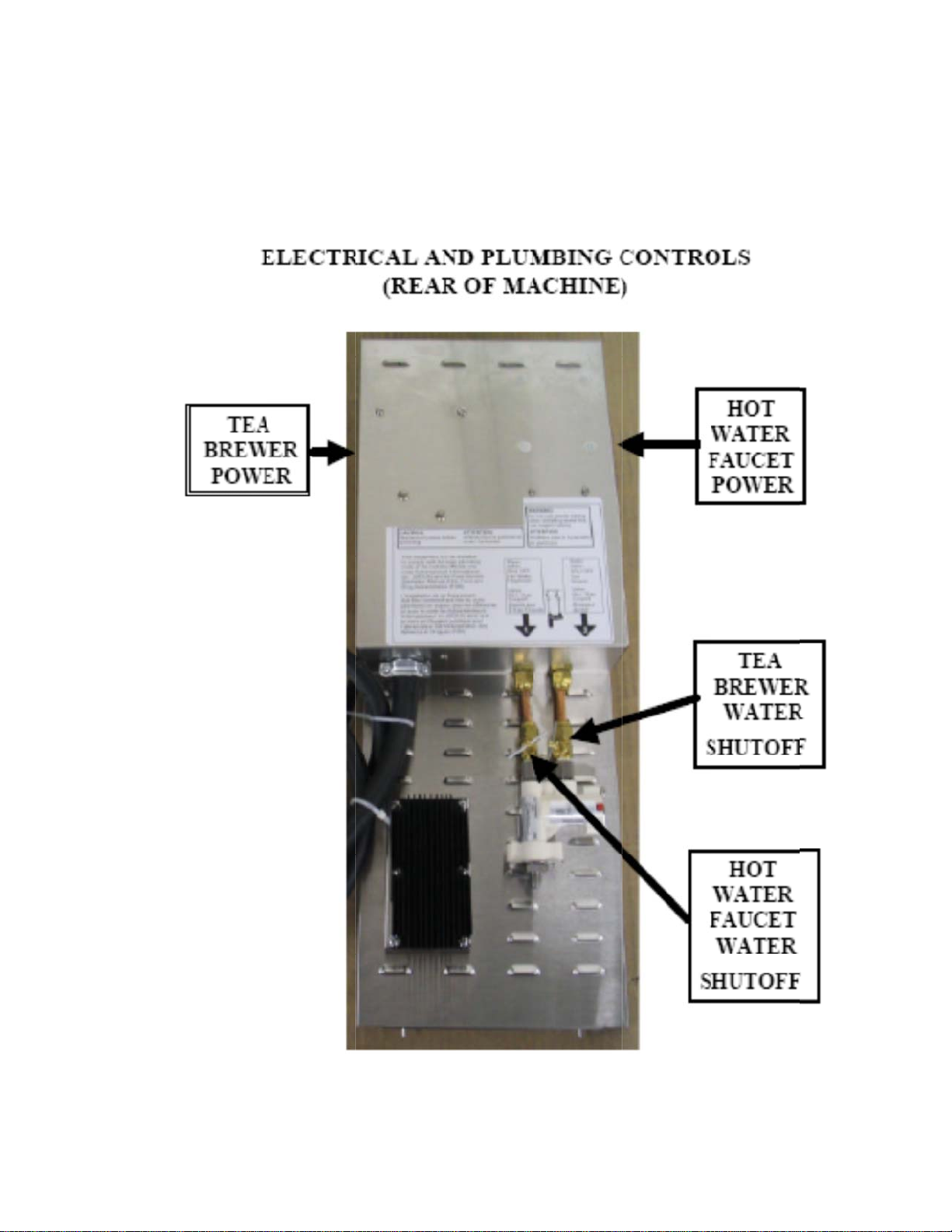
INSTRUCTION SHEET FOR AKPA-HW HOT WATER FAUCET FUNCTION
Follow the installation instructions using the main manual. Be sure proper waterline is connected to the brewer and the
water is turned on. Also, be sure when plugging in the unit that it is connected to the proper size, voltage and
amperage receptacle. When ready to fill the rear hot water tank use the following instructions:
• On the rear of the unit turn the UPPER on-off switch to the ON position. The water will immediately start to fill the tank.
• The water will continue to fill the tank until it reaches the lower probe (approximately 2 minutes). At this time the water
level in the tank is too low to draw any water from the hot water faucet. Also at this time the thermistor will activate the
tank element and will heat for approximately 10 minutes 30 seconds.
• When the water temperature reaches within 5 degrees of the set point (205F, 96C) the water will again fill the tank
until the water level reaches the upper probe. The tank element will be reactivated and will continue to heat for
approximately 5 minutes. Water can now be drawn from the hot water faucet.
• The temperature is factory set at 205F, 96C. The temperature can be adjusted by turning the gray adjustment knob on
the hot water dispenser board in the direction of the plus or minus (+ OR -) as indicated on the label above the knob.
The maximum temperature is 210F, 99C.
The hot water tank portion of the brewer is now ready for use.
The following pages pertain to the HOT WATER FAUCET FUNCTION of the machine.
14
Page 15

13A
11A
12A
Issued August 2013
15
Page 16

A
Issued August 2013
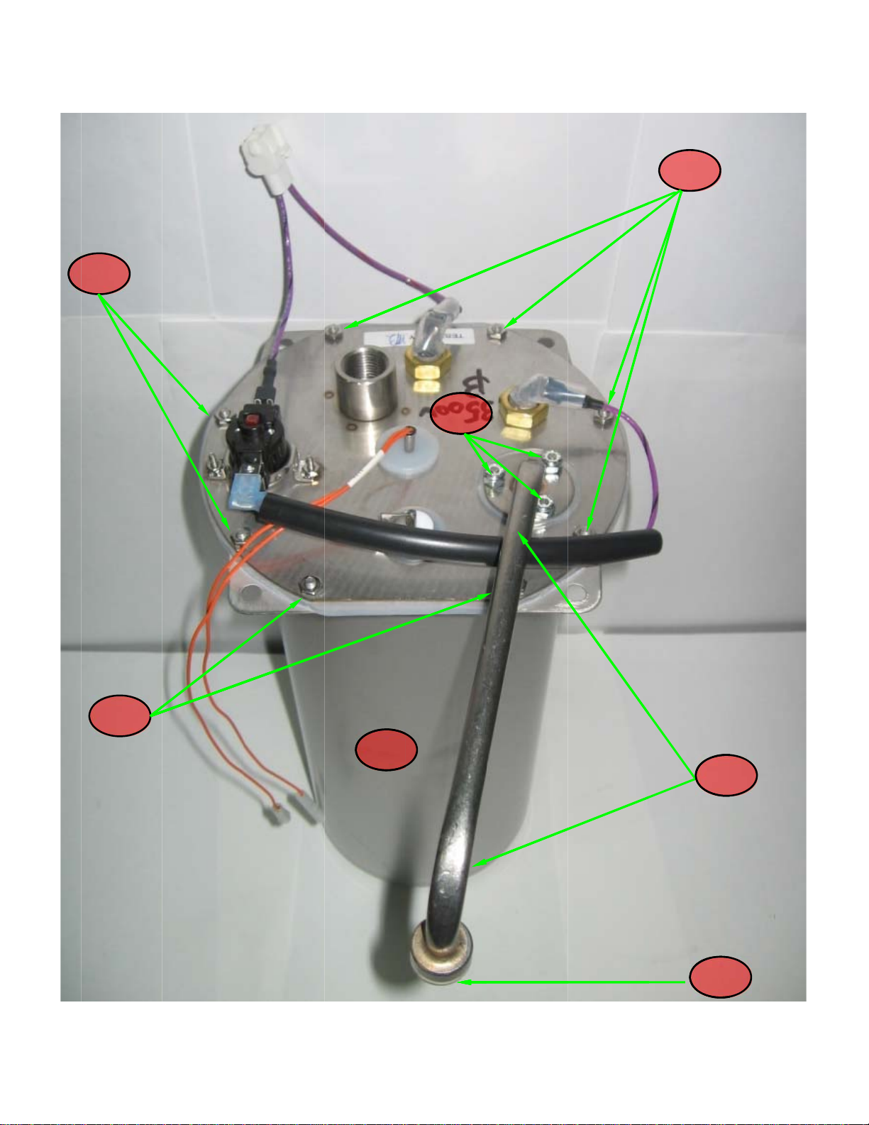
PARTS LIST-HOT WATER TANK ASSY
ITEM # PART # DESCRIPTION QTY
1 781468 FITTING, FAUCET 1
2 800244 GASKET, NYLON-.671 X .937 X .062 1
3 119879 NUT,FAUCET,3/8-18, CHROME PLATED 1
4 100190 NUT, ½-20, JAM, BRASS 2
5 100409 GASKET, BRASS .520ID, TIN PLATE 3
6 100269 BRACKET, HIGH LIMIT THERMOSTAT 1
7 111593 THERMOSTAT, MANUAL RESET 1
8 110978 TUBE-ASSY, SPRAYHEAD, PC 2
9 100025 GASKET, SPRAYHEAD (SILICONE) 1
10 201173 NUT, SPRAYHEAD 7/16-20 SS 1
11 102836 GROMMET, SILICONE, NO SPLIT [Thermistor] 1
11A 500350 GROMMET, NEW WATER PROBE [500403 & 500404]** 2
12 119891 PROBE-SPOTWELDED [SHORT] 2.375 [SHRINK] (ORIGINAL) 1
12A 500404 PROBE ASSEMBLY 90 X 1.450” X .880” [SHORT]** (NEW) 1
13 119890 PROBE-SPOTWELDED [LONG] 3.25 [SHRINK] (ORIGINAL) 1
13A 500403 PROBE ASSEMBLY 90 X 2.32” X .880” [LONG]** (NEW) 1
**UPDATED GROMMET & WATER PROBE ASSEMBLIES CURRENTLY BEING USED.
14 151800 PROBE ASSY, THERMISTOR, C98 1
15 100149 ELBOW- ¼ COMP X 1/8 NPT 1
16 102831 CONNECTOR, FEMALE 3/8 COMP X 1/8 FEMALE PIPE 2
17 100030 GASKET, BRASS .566 ID TINPLATED 3
18 100431 NUT, BRASS 9/16-24 , TIN PLATED 1
19 100166 SLEEVE, 3/8 COMP BRASS 1
20 100170 NUT, 3/8 COMP BRASS 1
21 119886 TUBE, 3/8” SS INLET 14” 1
22 119882 GASKET-TANK .062 SILICONE FD
23 111727-10 ELEMENT, MAIN 2000W 240V 1
Item # ITEMS NOT PICTURED Qty
102119 INSULATED SLEEVE (RIGHT ANGLE) 2
100065 SCREWS (LID TO TANK) 4
119856 14 GA V/BLK WIRE 1
119880 SILICON, 15” (FAUCET TUBE) 1
119885 TUBE, FILL 1
16
1
Page 17

Issued Aug
ust 2013
17
Page 18

A
Issued August 2013
PARTS LIST-HOT WATER/ TEA MISC.
ITEM
#
1 119911 COVER ASSY, AKPA,HW 1
2 119904 COVER,REAR, AKPA, HW 1
3 111719 BOARD, HOT WATER DISPENSE 1
4 110958 RELAY, 12V DC, SPST, 30 AMP 1
5 120805 VALVE, ASSY, AKPA 2
6 119894 ASSY, TUBE, INLET, HW, ¼ COPPER 1
7 119889 ASSY, TUBE, DISCHARGE, AKPAHW 1
8
9 119907 COLUMN, AKPAHW 1
10 121263 FAUCET, TH HOT WATER 1
PART # DESCRIPTION QTY
119909
119897
WRAPPER, LH
SSY, SPOTWELD, WRAPPER RH
18
1
1
Page 19

HOT WATER FAUCET TROUBLESHOOTING GUIDE
PROBLEM PROBABLE CAUSE REMEDY
1. No Water a.) Water turned off
b.) Water line not connected
c.) Faulty water inlet valve
2. Water Not Hot a.) Temperature setting too low
b.) Heater overload tripped
c.) Defective heater element
d.) Defective thermistor
3. Water Does Not Shut Off a.) Liquid level probe malfunction
b.) Faulty water inlet valve
4.) Water Boiling a.) Temperature setting too high
b.) Malfunctioning thermistor
Issued August 2013
a.) Turn on – open shutoff valve
b.) Ensure water line is connected
c.) Check valve and connections –
replace if necessary
a.) Adjust temperature setting (+)
b.) Reset hi-limit thermostat
c.) Replace heater element
d.) Replace thermistor
a.) Check probe connections
b.) Check valve and connections –
replace if necessary
a.) Adjust temperature setting (-)
b.) Replace thermistor
19
Page 20

Issued August 2013
20
Page 21

L
n
e
e
s
c
e
f
f
o
s
a
e
k
n
Lpc
w
b
v
o
m
t
2
o
A
Issued Aug
ust 2013
Identi
iquid Lev
R
ight-hand
o
2A] conne
[1
y
page 14 i
llow wire l
l Probe 1
hort probe
tem # 12
ted to a
ad.
ying the w
on
page 14 t
ater probe
the hot w
on the br
ter wiring
wer’s tan
diagram o
lid assem
page 19.
Liquid Le
eft-hand l
age 14 ite
onnected
ire lead.
ly
el Probe
ng probe
# 13 [13
o a grey
n
]
21
Page 22

M
0
2
3
4151617181920
2
A
M
a#6NuGaPV
e
d
W
eHe
rMa
eGaNuSpNuTa
3
K
0
e
S
”
G
W
P
m
m
a
S
n
S
u
S
e
e
1
T
E
0
P
”
c
a
W
A
n
”
b
0
0
r
t
m
P
y
s
3
5
n
A
W
E
0
w
s
2
2
h
[
A
A
]
ITE
1
2
3
4
5
6
7
8
9
1
11
1
1
1
21
2
#
T
NK LID
202027-10
PART #
100190
100212
100243
100409
100567
103016
119854
119865
120804
151800
500038
500350
500396
701305
100025
100061
101726
107240
704119
704221
781555
ASSE
Misc
8
BLY A
J
m Nut, 1/2-2
Lock Wash
t, 4-40 Hex
sket, Brass
C Tube, 3/8
L
ad Wire, 14
Li
Only, Spot
ire Harness,
Si
licone Tube,
T
mperature
ating Eleme
Si
licone Grom
Si
licone Grom
P
obe Assemb
nual Reset
llaneous Ta
sket, Spray
t, 8-32 Hex
ray Head T
t, 8-32 With
nk Only, K
Si
licone Gask
Si
licone Gask
9
PA DB
D
Brass
r, External T
S
.520 ID Tin
x 7500” 2 P
A Violet-Bl
elded AKP
Quick Disco
1/4" ID x 3/8
robe Assem
nt 3500W 12
et, No Slit .
et, Water P
ly, 1.537” Wi
afety Ther
k Assembly
Head
S
be Assembl
Nylon Insert
eries
t, Tank [Not
t, Delivery/Si
1& 4
-3 HW
SCRIPTION
ooth SS
lated
cs. Cut to 4.
ck 10” Teflo
-HW 3500
nect Tank-
OD x 1 5/8”
ly 5.75” C98
V [Not Sho
60”
obe With Bu
h Bushing
ostat, 215F
arts [11985
, AKLD
hown]
phon [Not S
9
500W
” & 7.5” [Not
1S-2N
lement AKP
n]
hing
5
]
own]
Issued Aug
119853
Shown]
HW
ust 2013
QTY
2
2
2
2
12”
1
1
1
2
1
1
1
1
1
1
1
11
1
3
1
1
1
15
2 &
7
6
3 & 14
10
12
22
Page 23
8
Issued Aug
ust 2013
17
17
19
17
20
1
16
A
23
Page 24

Issued August 2013
24
 Loading...