

Page 1
Man PN 102863
Rev 20080623
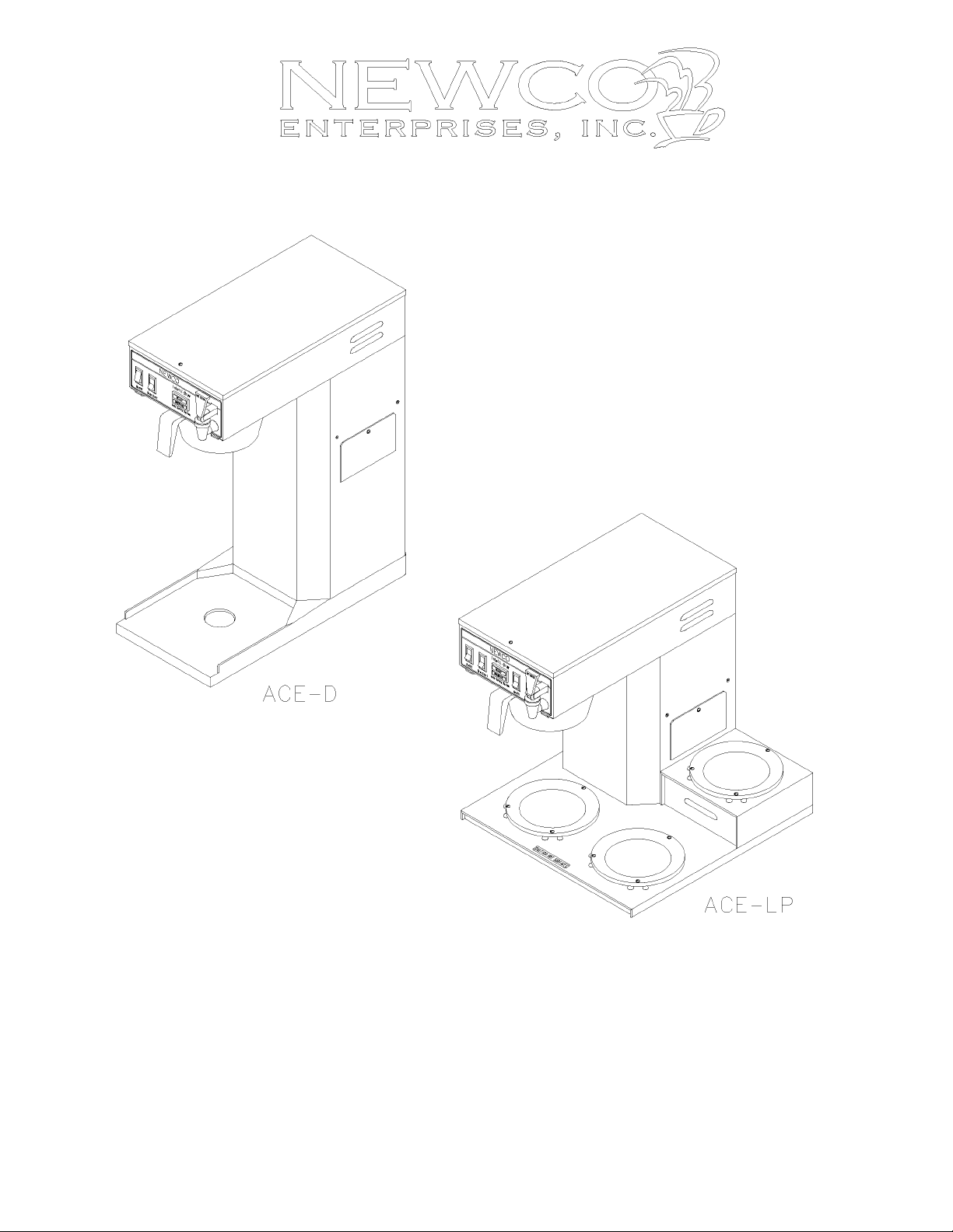
INSTALLATION, OPERATION, AND SERVICE MANUAL FOR
THE ACE SERIES - AUTOMATIC COFFEE EQUIPMENT
120 V Watts 120 V Amps 240 V
Model Warmers Width Depth Height Weight US Canada US Canada Watts Amps
ACE-S 3 8-1/2 16-1/2 17-7/16 29 1710 1410 14.3 11.8 3810 17.2
ACE-LP 3 15-1/2 16-1/2 15-7/8 31 1710 1410 14.3 11.8 3810 17.2
ACE-AP 0 8-1/2 17-11/16 22-1/4 29 1760 1410 14.7 11.8 3510 14.6
ACE-D 0 8-1/2 17-11/16 26-1/4 32 1760 1410 14.7 11.8 3510 14.6
ACE-TC 0 8-1/2 17-11/16 16-9/16 28 1760 1410 14.7 11.8 3510 14.6
ACE-LD 0 8-1/2 17-11/16 20-1/8 28 1760 1410 14.7 11.8 3510 14.6
ACE-TS 0 8-1/2 17-11/16 Varies 34 1760 1410 14.7 11.8 N/A N/A
Newco Enterprises, Inc. * 3650 New Town Blvd * St. Charles, MO 63301 * Ph 800.325.7867 * Fax 636.925.0029
Page 2
ACE CONTROL OVERVIEW
The ace series brewers have been upgraded to include the “Super Ace” control. This control has all the features of
the previous Ace control board with the additional options of pulse brewing, auto arm and half/full brew in one new
compact control. These additional options may or may not be activated on your unit and may require additional parts.
The following text outlines and explains the features and options.
Features:
Digital technology
Live probe
turns off the fill solenoid.
Overfill Protection
water level probe in the tank lid. This is intended to protect the unit from overflow should a fill error occur. When the
tank is filling on the initial set up, an error will occur since this is not enough time to allow the tank to fill. This error will
be indicated by a rapidly flashing brew light. The error may be cleared by holding down the brew start switch until the
light stops flashing.
Visa-brew
the brewing lamp flashes to help prevent the removal of the brew basket or serving vessel prematurely. This feature is
adjustable. Adjust the Visa-Brew time to allow sufficient time for hot beverage to drain from brew basket after
completion of the water delivery portion of the brew cycle.
Options:
Auto Arm
initiated, the control board verifies that the temperature in the tank is equal to the thermostat setting. If the water
temperature is not at proper temperature, the brew is stored in memory and light will flash to indicate brewing. When
the temperature rises to the proper setting, the brewer will automatically begin to brew. If your brewer does not already
have the auto arm feature the brewer will require additional parts and wiring changes to convert it.
Half brew
wiring changes. Basic kit part number is 120032.
Pulse brew
contact time with the coffee grounds. This option can be activated by moving the jumper designated (J1) from disabled
to the enabled position. Basic kit part number is 108082.
– This feature is activated when the hot water faucet is in use. When water reaches the water level probe it
- This feature helps to communicate to the user that a brew cycle is in process. Once the brew cycle begins,
- Pre-checks water temperature before brewing to ensure optimum brew temperature. When a brew cycle is
– This option allows the brewer to brew a half or full decanter. This option will require additional parts and
– Gives more consistent brew cycle.
- The Super Ace has a maximum fill valve run time of 1-1/2 minutes if the water does not contact the
- This option allows the brewer to turn the fill valve on and off during the brew cycle which extends water
WARNING: - Read and follow installation instructions before plugging or wiring
in machine to electrical circuit. Warranty will be void if machine is connected
to any voltage other than that specified on the name plate.
Additional Options
PDS - The PDS flow control is an optional flow control valve that is more accurate than a traditional flow control over a
wide range of water pressures and will maintain its volume setting for many years within the harsh water environment
that coffee brewing equipment must operate. See pages 7 and 8 for additional information on this feature.
TS models – The Ace series brewer is available as a telescoping brewer. These brewers are equipped with a
telescoping column to allow periodic adjustment of the brewer height. This feature allows continued use of the same
piece of brewing equipment although the dispensers may change over time. See pages 9 and 10 for additional
information on this feature.
PAGE 2
Page 3
PLUMBER'S INSTALLATION INSTRUCTIONS
CAUTION: Power to brewer must be OFF before proceeding with plumbing installation.
1. Flush water line before installing brewer. Brewer should be connected to COLD WATER LINE only.
2. Water pressure should be at least 20 lbs. For less than a 25 ft run, use 1/4" copper tubing and connect to 1/2"
or larger water line. For longer runs, use 3/8" copper tubing & connect to 1/2" or larger water line and provide
an adapter fitting for connection to the brewer. Recommended flow rate from water line is 1 gpm.
3. If installed with saddle valve, the valve should have a minimum of 1/8" port hole for up to 25 ft run, and 5/16"
port hole for over 25 ft runs.
4. Connect incoming water line to the elbow extending from the solenoid valve on the back of the brewer.
Manufacturer recommends connecting to copper tubing.
5. Ensure that tank heater switch on the rear of brewer is in the off position. Connect brewer to appropriate
electrical supply as indicated on serial tag.
INSTALLATION INSTRUCTIONS
FILL BREWER TANK WITH WATER BEFORE CONNECTING TO POWER SUPPLY !
1. Place the decanter under brew basket, remove brewer top cover and tank lid and pour three decanters of water
into the tank. Water should come through the brew basket as the third decanter empties of water. Re-install
tank lid and top cover.
2. Plug or wire brewer to appropriate voltage circuit as indicated on serial tag. Turn (master / tank) switch (located
in rear of equipment) to the ON position. Note: Brewer is shipped with thermostat turned on.
3. Place an empty decanter in position below the brew basket. With the decanter in place turn the lower warmer
switch, power switch for dispenser models, to the ON position and depress brew start switch. When water
begins to flow from the brew basket hold a suitable container beneath faucet and momentarily open the faucet
to remove any entrapped air. Turn off lower warmer or power switch as applicable to cancel brew cycle.
4. Empty decanter and replace below the brewbasket. Turn on the lower warmer switch, power switch for
dispenser models, and depress the brew start switch to begin a brew cycle, checking the volume of water
delivered into decanter. Adjust timer to deliver desired amount of water. Turn timer dial clockwise to increase
volume of water, counter clockwise to decrease it. On models with Auto-Arm brewer will not run until fully
heated or if (master / tank) switch is turned off.
5. The brewing light located on the face of the machine below the ready light is part of the "Vis-A-Brew" safety
system. This flashing amber light warns the user that hot liquid is draining from the brew funnel. This light
should continue to flash until all liquid has drained into decanter. This control is preset at the factory but may
be adjusted independent of the brew timer for your specific brewing conditions (i.e., filter type, coffee grind,
etc.). Clockwise rotation of the knob will increase duration of the flashing while counterclockwise rotation will
decrease the active time of the light. Both the timer and Vis-A-Brew adjustments are located behind the access
panel on the side of the brewer except on telescoping models, where they are located below the top cover.
6. Allow 10 to 15 minutes for water in tank to heat to brewing temperature. After water has reached brewing
temperature (thermostat will click off and green ready light will be lit) run one cycle to check for the proper
temperature setting with an accurate thermometer. Take the temperature of this water at a point below the brew
basket opening, at the start of the brew cycle and when the decanter is half full. Recommended temperature of
the water is approximately 195 F. (Note: Brew cycle may be canceled by turning the rocker switch back to the
OFF position.)
7. In higher altitude locations (5000 feet above sea level) the thermostat may have to be adjusted lower to prevent
boiling.
8. CAUTION: The water faucet will dispense hot water when the handle is actuated. The faucet system may be
operated during timed portion of brew cycle without yielding a short pot.
PAGE 3
Page 4

COFFEE PREPARATION PROCEDURES
1. Place filter into brew basket.
2. Put the proper amount of coffee into the filter.
3. Slide the brew basket into holder.
4. Place the appropriate empty decanter into position below the brew basket. For airpots first open lid and remove
pump stem. For other dispensers remove the lid unless it is a brew thru design. Turn lower warmer switch, or
power switch for dispenser brewers, to the ON position.
5. Press brew start switch. (Brew cycle may be canceled by turning the rocker switch back to the OFF position.)
6. Hot water will be delivered through the sprayhead. This distributes the hot water evenly over the coffee bed
within the brew basket. The coffee brew will drain from the brew basket into the decanter below.
7. The resultant coffee brew should be crystal clear and have the desired properties attainable through excellent
extraction.
8. Turn off the warmer and power switches as applicable when not in use. Red light in switch indicates when
power is on. Note: The solenoid will not run to replace water in tank that is drawn off from the faucet when the
lower warmer switch, or power switch for dispenser models, is in the OFF position. However when the brew
cycle is again initiated the tank will fill before cycle begins to prevent a short pot.
9. To clean brew basket simply remove from brew rails and dump filter into waste basket. The brewing process,
as described above, can now be started again.
LIMING: To prevent liming problems in tank, sprayhead tubes, and vacuum breakers fittings remove sprayhead and
insert deliming spring all the way into the tank. When inserted into tank properly, no more than ten inches of the spring
should be visible at the sprayhead fitting. Saw back and forth five or six times. T his will keep fittings open and clear of
lime. In hard water areas this should be done everyday. This process takes approximately one minute. In all areas the
sprayhead should be cleaned at least once a week. Where bad liming has already occurred, a new complete tank
assembly may be installed.
WARRANTY
Newco coffee brewers are warranted against defects in workmanship or materials, under normal use, for one
year from the date of purchase.
Liability in all events is limited to the purchase price paid and liability under the aforesaid warranty is limited to
replacing or repairing any part or parts which are defective in material or workmanship, and returned to our factory,
shipping cost prepaid. No warranty expressed or implied, other than the aforesaid is made or authorized by Newco
Enterprises, Inc.
Prompt disposition will be made if item proves to be defective, within warranty. Before returning any item, write
or call Newco, or the dealer from whom the product was purchased, giving model number, serial number, and date of
purchase, and describe nature of the defect. If damage was incurred during transit to you, file claim with the carrier.
PAGE 4
Page 5

TROUBLE SHOOTING GUIDE
SYMPTOM POSSIBLE CAUSE WHAT TO CHECK REMEDY
CAN'T START BREW CYCLE
NO HOT WATER
STEAMING OR SPITTING
AROUND FUNNEL
DRIPPING
WATER KEEPS RUNNING
OVER FLOWING
1. No water.
2. No power.
3. ON/OFF or lower warmer
switch. (Power switch on
dispenser brewers.)
4. Brew start switch.
5. Control board harness.
6. Solenoid valve.
1. Tank heater.
2. Hi-limit thermostat or main
thermostat.
1. Main thermostat.
2. High altitude.
1. Not siphoning properly.
2. Solenoid valve not seated
properly.
1. Solenoid valve.
2. Start switch.
3. Control board/timer.
4. Micro switch.
(Located behind faucet)
1. Receiving decanter not
completely empty at the start of
the brew cycle.
2. Not siphoning properly.
1. Incoming water lines and water
shutoff valve.
2. Fuse or circuit breaker. Power
cord and plug connections.
3. Is switch turned on?
4. Switch continuity. (Normally
open).
5. Wire leads to solenoid and
switch terminals.
6. (A) Voltage at solenoid valve
terminals. Start a brew cycle and
check for proper voltage.
(B) If correct voltage is present
at terminals, check for water at
line pressure on the inlet side of
solenoid valve.
1. Check the voltage at the tank
heater terminals. Refer to serial
tag for proper voltage.
2. Check the voltage between the
white wire on the tank heater
terminal and the incoming terminal
(blue wire) on the hi-limit
thermostat, then the outgoing
terminal (black wire) on the hi-limit
thermostat.
1. Thermostat Points stuck or out
of calibration.
2. Located above 5,000 feet.
1. Water should flow freely from
the sprayhead.
2. Solenoid valve assembly.
(SEE FIGURE 3)
1. Refer to "DRIPPING" Step 2.
2. Remove wires from switch and
check continuity.
3. Control board is non-repairable.
4. (A) Remove wires from switch
and check continuity.
(B) Switch arm or bracket
binding with handle preventing
shut off.
1. Operating instructions.
2. Refer to "DRIPPING" Step 1.
1. Be sure water shutoff valve is open.
2. Replace or reset circuit breaker as
required. Unit should be plugged in
securely.
3. Switches must be on to start brew cycle.
If switch does not make and break contact
between terminals 1 and 2, replace switch.
4. If brew switch does not make and break
contact, replace brew start switch.
5. Make sure these connections are tight. If
so, and all else checks out OK, replace
timer.
6. (A) If voltage is not present at terminals
refer to steps 2 through 5.
(B)
If voltage is present at terminals and
water at line pressure is present on the inlet
side of the solenoid, but not present on the
outlet side, replace solenoid or solenoid
coil.
1. (A) If correct voltage is present at the
tank heater terminals, and water in tank is
not being heated, replace the tank heater.
(B) If voltage is not present at the tank
heater terminals refer, to Step 2.
(C) If incorrect voltage is present at the
tank heater terminals, check voltage at
outlet.
2. (A) If voltage is present on the incoming
terminal of the hi-limit thermostat, but not
on the outgoing terminal, replace the hi-limit
thermostat.
(B) Check voltage between black and
white wire on the receptacle. If voltage is
not present check outlet or circuit breaker.
(C) If voltage is not present on the
incoming terminal of the hi-limit thermostat,
replace the main thermostat.
1. Thermostat should be calibrated or
replaced.
2. See installation instructions.
1. (A) Clean sprayhead holes.
(B) Check tightness of sprayhead tube.
(C) See "LIMING" page 3.
2. Be sure spring is in place and any
particles are cleaned from diaphram. If
diaphram is worn or mutilated, replace
solenoid valve.
1. Refer to "DRIPPING" Step 2.
2. If switch does not make and break
continuity, replace switch.
3. If timer will not shut off, replace board.
4. (A) If switch does not make and break
continuity replace switch.
(B) Replace.
1. Always start brew cycle with receiving
decanter empty.
2. Refer to "DRIPPING" Step 1.
PAGE 5
Page 6

TROUBLE SHOOTING GUIDE
SYMPTOM POSSIBLE CAUSE WHAT TO CHECK REMEDY
IRREGULAR YIELD
DRY COFFEE REMAINING
IN BREW BASKET AFTER
BREWING
WEAK COFFEE
SOLENOID CHATTER OR
HOWLING
COLD WARMER STATION
FAUCET DRIPPING
FAUCET FLOW SLOW
1. Not siphoning properly.
2. Control board/timer.
3. Fluctuating water pressure.
4. Solenoid valve.
5. Flow washer.
6. Micro switch.
1. Filters.
2. Not siphoning properly.
3. Improper loading of the brew
basket.
1. Filters.
2. Low water temperature.
3. Not siphoning properly.
4. Improper loading of brew
basket.
5. Missing sprayhead.
1. Brewer connected to hot water
line.
2. Vibration.
3. High water pressure.
4. Water hammer.
5. 60 Cycle vibration.
1. Warmer - defective.
2. Warmer On/Off switch.
3. Bad harness.
1. Clogged valve seat.
1. Entrapped air in line.
2. Faucet clogging.
1. Refer to "DRIPPING" Step 1.
2. Timer consistency. Time
several brew cycles.
3. Water pressure.
4. Refer to "DRIPPING" Step 2.
5. Possible lime build up in flow
washer or flow control.
6. Refer to "WATER KEEPS
RUNNING" Step 4.
1. Are correct filters being used.
2. Refer to "DRIPPING", Step 1.
3. Filter and coffee in brew basket.
1. Are correct filters being used.
2. Check water temperature. Refer
to installation instructions.
3. Refer to "DRIPPING" Step 1.
4. Filter and coffee in brew basket.
5. Check for sprayhead.
1. Incoming water line.
2. If brewer is on a metal stand or
counter, neither the bottom pan
nor copper tubing to the brewer
should touch the counter.
3. Water pressure on incoming
line.
4. Incoming plumbing.
5. Screws on solenoid valve.
1. Voltage at warmer terminals
should be 120 V ac.
2. If voltage is not present on
warmer terminals, check continuity
of the switch.
3. Check connections between
harness and switch, and between
switch and warmer.
1. Valve seat.
1. Tank to faucet line.
2. Faucet.
1. Refer to "DRIPPING" Step 1.
2. If times are irregular replace board.
3. If pressure fluctuates 10-20 PSI
during operation of brew cycle, add a
pressure regulator to inlet side of
brewer, set to lowest pressure level
registered. adjust timer to yield correct
water level.
4. Refer to "DRIPPING" Step 2.
5. (A) Replace flow washer and clean
screen. Screen is located inside
solenoid.
(B) Flow washer must be .250 GPM.
6. Refer to "WATER KEEPS RUNNING"
Step 4.
1. Insert correct filter into brew basket.
2. Refer to "DRIPPING" Step 1.
3. Filter should be centered in the brew
basket and coffee bed should be level.
1. Insert correct filter into brew basket.
2. Adjust thermostat control knob to
obtain correct water temperature.
3. Refer to "DRIPPING" Step 1.
4. Filter should be centered in brew
basket and coffee bed should be level.
5. Install sprayhead.
1. Should be connected to cold water
line.
2. Adjust as necessary.
3. If water pressure is over 90 PSI install
a pressure regulator and adjust to 50
PSI.
4. This is not the fault of the brewer and
can usually be corrected by rearranging
some plumbing or adding an air
chamber to the incoming water line.
5. Screws should be tight. Tighten as
required.
1. If voltage is present on terminals of
warmer element, but warmer will not
heat, replace the element.
2. If switch does not make and break
continuity (between terminals 1 and 2)
when turned on and off, replace switch.
3. All connections should be tight.
1. Disassemble and clean or replace as
required.
1. Refer to "INSTALLATION
INSTRUCTIONS" Step 3.
2. Clean or rebuild faucet.
PAGE 6
Page 7

ACE SERIES BREWERS – REPLACEMENT PARTS LIST
Part No Description Part No Description
100010 Warming plate ass'y 120 V, black 102798 Tank ass'y, 120 V 1400 W
100187 Warming Element, 120 V 100 W 102859 Tank ass'y, 120 V 1750 W
102581 Element main heating, 1100 W 120 V 102746 Tank ass'y, 240 V 3500 W
102580 Element main heating, 1400 W 120 V 104012 Tank lid ass'y
100071 Element main heating, 1750 W 120 V 781181 Gasket, silicone tank
102850 Element main heating, 3500 W 240 V 100024 Sprayhead, S/S 5 hole
704227 Main thermostat 102820 Solenoid valve assembly with fittings
111593 Hi-limit Thermostat, manual reset 102780 Solenoid valve, S-45
100085 Lighted rocker switch 120 V 201158 Repair kit, solenoid valve
201985 Brew switch, black, rectangular 790019 Gasket, flow control
102775 Dual lamp, brewing/ready indicating 120 V 100290 .250 flow control washer
102862 Micro switch &bracket ass'y 102770 Faucet w/red handle
102841 Micro switch only 102268 Seat cup for faucet
121723 Control board ass'y with bracket, (non TS models) 110322 PDS low/flow assembly
111725 Control board ass'y with bracket, (TS models) 102783 Sprayhead tube ass'y
100500 ON/OFF switch 100025 Sprayhead gasket
110985 Brew basket assy, black plastic 100078 Bumper foot with screw
201954 Filter pack brew basket 108067 Probe ass'y, weldment
102800 Brew rail, LH 201173 Sprayhead nut
102799 Brew rail, RH
102370 Brew basket, S/S small
104010 Brew rail, RH, S/S basket
104011 Brew rail, LH, S/S basket
ELECTRICAL COMPONENTS
BREWBASKETS
TANK AND PLUMBING
MISC.
For additional replacement parts information refer to Ace Series replacement parts manual, P/N 108054.
PDS Flow Control Supplemental Information
The PDS flow control system is the result of many years of engineering effort to create a flow control valve that would
be accurate over a wide range of water pressures as well as maintain its volume setting for many years within the harsh
water environment that coffee brewing equipment must operate.
The valve has been designed to allow for adaptation to all varieties of brewers, and is available in both a low flow (0.15
GPM to 0.35 GPM) and high flow (0.56 to 1.25 GPM) model. Both models have adjustable flow rates to any setting
within the specified range. The low flow models are identifiable by their red bonnet while the high flow models have a
green bonnet. See item 14 in figure below.
Other features designed into the valve include an internal water strainer, a non-regulated water supply for connecting to
independent faucets, an easy to adjust knob for setting the flow rate, double O-ring swivel fittings to eliminate leaks due
to equipment being moved, and most importantly a porcelain sleeve and piston assembly that is self cleaning and
cannot be affected by chemicals within the water supply. The system has been designed to operate over a wide range
of water pressures, from 10 PSI to 70 PSI for low flow models and from 40 PSI to 110 PSI for high flow models, with an
accuracy of +/- 1%.
The time setting of the brewer timer works in conjunction with the flow rate set on the PDS valve. This determines the
volume of water being delivered for the brew cycle. If the valve is set at a rate of .25 GPM and the timer is set for 2
minutes, the volume delivered wil be .25 x 2 or one half gallon (64 oz). Refer to table 1 for other flow rates, timer
settings and volumes. Flow rate accuracy is critical as the timer setting will remain constant.
PAGE 7
Page 8

T a b l e 1 - T i m e r S e t t i n g R e q u i r e d T o O b t a i n D e s i r e d V o l u m e
Desired F l o w R a t e – I n G a l l o n s P e r M I n u t e
Volume 0.175 0.200 0.220 0.250 0.300 0.350 0.500 0.750 1.000
1 liter 91 79 71 63 53 45 32 21 16
64 oz 171 150 136 120 100 86 60 40 30
72 oz 193 169 153 135 113 96 68 45 34
2.2 liters 199 174 159 139 116 100 70 46 35
2.5 liters 226 198 180 159 132 113 79 53 40
3 gallons 1029 900 818 720 600 514 360 240 180
B r e w T I m e S h o w n i s i n S e c o n d s
T a b l e 2 – P D S P a r t s L i s t
Item Part No Description Item Part No Description
1 110217 PDS Flow Valve Body 8d 103936 Adapter, 1/8 NPT Fem x .750 O-Ring
2 110580 Retainer, Outlet Fittings 9 110219 O-Ring, .625 ID x .750 OD
3 110218 O-Ring, .375 ID x .500 OD 10 110213 O-Ring, .562 ID x .750 OD
4a 110220 Adapter, 1/4 FL x .500 O-Ring 11 110117 Sleeve, Ceramic
4b 110108 Plug, .500 O-Ring 12 110116 Piston, Ceramic
4c 110212 Adapter, 1/8 NPT x .500 O-Ring 13a 110101 Spring, Low Flow Valve
4d 110111 Adapter, 3/8 Stem x .500 O-Ring 13b 110226 Spring, High Flow Valve
5 110223 Screw, #8 x .500 S/S Hex Head 14a 110216 Bonnet, Low Flow Valve
6 110109 Retainer, Inlet Fitting 14b 110227 Bonnet, High Flow Valve
7 110114 Filter Screen, S/S 15 110214 O-Ring, .312 ID x .500 OD
8a 110221 Adapter, 1/4 FL x .750 O-Ring 16 110222 Plug, Flow Adjustment
8b 110211 Adapter, 1/8 NPT x .750 O-Ring 17 110098 Retainer, Flow Adjustment
8c 110112 Adapter, 3/8 Stem x .750 O-Ring
PDS Valve Diagram
PAGE 8
Page 9

Telescoping Brewer Supplemental Information
Telescoping Brewer Principal of Operation - Your brewer is equipped with a telescoping column to allow periodic
adjustment of the brewer height. This feature allows continued use of the same piece of brewing equipment although
the dispensers may change over time. The brewer has an inner and an outer column which slide up and down against
each other. Three functional elements combine together to give the telescoping brewer its unique characteristics and
strength. Refer to figure on next page.
• A flat “spring” lock (B), secured to the tank shelf, engages detents located internally on both sides of the
wrapper and carries the bulk of the units weight.
• Retainer straps (F), secured after height adjustment, prevent the head from lifting.
• Screws (D),which secure the outer back to the column, tie the inner and outer column together providing
Adjusting Telescoping Brewers
1. Perform the following steps in the order outlined prior to attempting brewer adjustment.
• Disconnect Power from electrical supply.
• Disconnect brewer from water supply.
• Allow brewer to cool.
• For easier adjustment, remove brewer top cover and tank lid, then siphon water from tank.
2. Remove the outer lower back (H) from the outer column (M) by removing the two screws (D) near the backs
3. Remove the inner lower back (K) from the inner column (N). It is not necessary to remove the other two brewer
4. Locate the two brass knurled nut assemblies (E) attached to the retainer straps (F) at the front of the brewer.
5. The brew head is now able to be adjusted up and down depending on its current position. Multiple techniques
6. Slide the knurled nut assemblies (E) to a readily accessible location for future adjustments and tighten them
7. Replace the inner lower back (K) on the inner column.
8. Replace the outer lower back (H) in position on column and locate the obround slot which lines up with a hole in
9. Refill tank with water and replace tank lid and brewer top cover. Reconnect brewer to water and electrical
additional strength and stability.
lower edge. Note these screws secure the columns together, so use caution as the head assembly will be
loose once they are removed.
back panels (G & J).
Loosen the assembly by turning nut counterclockwise. DO NOT REMOVE.
may be used to raise or lower the brew head so use the one that works best for you.
To RAISE the brew head:
Grasp the outer column (M) from behind with one arm while holding the base (O) in position with the other.
Raise the brewer to the appropriate height for your dispenser and brewbasket combination. The brew head
may also be raised by lifting against the bottom of the tank shelf (A) or by using the handles (C), located on the
flat spring, while holding the brewer base in position. Ensure that the flat spring lock (B) fully engages an entire
row of detents on each side of the brewer and that the rows are the same height from side to side.
To LOWER the brew head:
Grasp the outer column from behind with one arm for support while squeezing the spring lock handles (C)
together. Lower the brewer to the appropriate height for your dispenser and brewbasket combination. Ensure
that the flat spring lock fully engages an entire row of detents on each side of the brewer and that the rows are
the same height from side to side. At the lowest position ensure that the spring lock does not set on the screws
which secure the column to the base (L).
securely.
the inner column. Secure the back to the columns with the screws previously removed. Check brewer for
stability.
supply and follow brewer operating instructions for setup and calibration of new brew volume if required.
Note: The screws (I) holding upper inner back should not normally be removed. If they are removed they
should only be replaced with screw of same length to avoid interference with internal components during
adjustment.
PAGE 9
Page 10

Telescoping Brewer Chasis Diagrams
Telescoping Brewer 120 V Wiring Diagram
PAGE 10
Page 11

WIRING DIAGRAMS
PAGE 11
Page 12

Wiring Continued - Thermal Brewer Shown With Autoarm
240V 120V
Miscellaneous Figures
Valve Section View Micro Switch Section View
PAGE 12
 Loading...