

Page 1

Artisan Technology Group is your source for quality
new and certied-used/pre-owned equipment
• FAST SHIPPING AND
DELIVERY
• TENS OF THOUSANDS OF
IN-STOCK ITEMS
• EQUIPMENT DEMOS
• HUNDREDS OF
MANUFACTURERS
SUPPORTED
• LEASING/MONTHLY
RENTALS
• ITAR CERTIFIED
SECURE ASSET SOLUTIONS
SERVICE CENTER REPAIRS
Experienced engineers and technicians on staff
at our full-service, in-house repair center
Instra
Remotely inspect equipment before purchasing with
our interactive website at www.instraview.com
Contact us: (888) 88-SOURCE | [email protected] | www.artisantg.com
SM
REMOTE INSPECTION
View
WE BUY USED EQUIPMENT
Sell your excess, underutilized, and idle used equipment
We also offer credit for buy-backs and trade-ins
www.artisantg.com/WeBuyEquipment
LOOKING FOR MORE INFORMATION?
Visit us on the web at www.artisantg.com for more
information on price quotations, drivers, technical
specications, manuals, and documentation
Page 2

C-25 Classic Incubator
& C-25KC Classic
CFC-Free Refrigerated
Incubator Shakers
MANUAL NO: M1246-0051
Revision H
October 29, 2004
NEW BRUNSWICK SCIENTIFIC CO., INC.
BOX 4005 • 44 TALMADGE ROAD • EDISON, NJ 08818-4005
Telephone: 1-732-287-1200 • 1-800-631-5417
Fax: 732-287-4222 • Telex: 4753012 NBSCO
Internet: http://www.nbsc.com • E-mail: [email protected]
Artisan Technology Group - Quality Instrumentation ... Guaranteed | (888) 88-SOURCE | www.artisantg.com
Page 3

2
M1246-0051 YC-25 & C-25KC Classic Incubator Shakers User’s Guide
Artisan Technology Group - Quality Instrumentation ... Guaranteed | (888) 88-SOURCE | www.artisantg.com
Page 4

3
INTERNATIONAL OFFICES:
BELGIUM
New Brunswick Scientific NV-SA
Stationsstraat 180/4
3110 Rotselaar
België/Belgique
Tel: 32 (0)16 56 28 31
Fax: 32 (0)16 57 27 53
E-mail: [email protected]
CHINA
New Brunswick Scientific Co., Inc.
Room 1501, Xiangjiang Building, No. 18
Lane 1265, Zhongshan Road (W)
Shanghai 200051, P.R. China
Tel: 86 21 3223 0203
Fax: 86 21 6278 7182
E-mail: [email protected]
FRANCE
New Brunswick Scientific SARL
3, rue des Deux-Boules
75001 Paris
France
Tel: 33 (0)1 4026 2246
Fax: 33 (0)1 4026 5423
E-mail: [email protected]
GERMANY
New Brunswick Scientific GmbH
In Der Au 14
D-72622 Nürtingen
Deutschland
Tel: 49 (0)7022 932490
Fax: 49 (0)7022 32486
E-mail: [email protected]
THE NETHERLANDS
New Brunswick Scientific BV
Kerkenbos 1101, 6546 BC Nijmegen
P.O Box 6826, 6503 GH Nijmegen
Nederland
Tel: 31 (0)24 3717 600
Fax: 31 (0)24 3717 640
E-mail: [email protected]
UNITED KINGDOM
New Brunswick Scientific (UK) Ltd.
17 Alban Park
St. Albans, Herts. AL4 0JJ
United Kingdom
Tel: 44 (0)1727 853855 or 0800 581331
Fax: 44 (0)1727 835666
E-mail: [email protected]
Web: www.nbsuk.co.uk
New Brunswick Scientific Co., Inc. User’s Guide
Artisan Technology Group - Quality Instrumentation ... Guaranteed | (888) 88-SOURCE | www.artisantg.com
Page 5

4
THIS PAGE IS INTENTIONALLY BLANK
M1246-0051 YC-25 & C-25KC Classic Incubator Shakers User’s Guide
Artisan Technology Group - Quality Instrumentation ... Guaranteed | (888) 88-SOURCE | www.artisantg.com
Page 6

5
WARNING!
This equipment must be operated as described in this manual.
If operational guidelines are not followed, equipment damage and
personal injury can occur. Please read entire User’s Guide
before attempting to use this unit.
New Brunswick Scientific Co., Inc. User’s Guide
Artisan Technology Group - Quality Instrumentation ... Guaranteed | (888) 88-SOURCE | www.artisantg.com
Page 7

6
THIS PAGE IS INTENTIONALLY BLANK
M1246-0051 YC-25 & C-25KC Classic Incubator Shakers User’s Guide
Artisan Technology Group - Quality Instrumentation ... Guaranteed | (888) 88-SOURCE | www.artisantg.com
Page 8
7
Copyright Notice
New Brunswick Scientific Company, Inc.
Box 4005 44 Talmadge Road
Edison, New Jersey 08818-4005
© Copyright 2004 New Brunswick Scientific Co., Inc.
All Rights Reserved.
Reproduction, adaptation, or translation without prior written permission from
New Brunswick Scientific is prohibited.
Disclaimer Notice
New Brunswick Scientific Co., Inc. reserves the right to change
information in this document without notice. Updates to information in this
document reflect our commitment to continuing product development and
improvement.
Manual Conventions
#NOTE:
CAUTION!
Notes contain important and useful information
separate from text.
Caution messages appear before procedures
which, if not observed, could result in damage to
the equipment.
Warning messages alert you to specific
procedures or practices which, if not followed
correctly, could result in serious personal injury.
WARNING!
Bold Text in bold face type emphasizes key words or
phrases.
New Brunswick Scientific Co., Inc. User’s Guide
Artisan Technology Group - Quality Instrumentation ... Guaranteed | (888) 88-SOURCE | www.artisantg.com
Page 9

8
THIS PAGE IS INTENTIONALLY BLANK
M1246-0051 YC-25 & C-25KC Classic Incubator Shakers User’s Guide
Artisan Technology Group - Quality Instrumentation ... Guaranteed | (888) 88-SOURCE | www.artisantg.com
Page 10

9
W A R R A N T Y
Every Instrument manufactured by the
New Brunswick Scientific Co., Inc. is warranted to be free
from defects in material and workmanship. This apparatus, with
the exception of glassware, lamps and electrodes (where supplied),
is warranted against faulty components and assembly for 2 years
in the United States & Canada and for 1 year elsewhere. Our
obligation under this warranty is limited to repairing or replacing
the instrument or part thereof, which shall, upon our examination,
prove to be defective. The warranty period begins at the date of
shipment. This warranty does not extend to any NBS produ cts
which have been subjected to misuse, neglect, accident or
improper installation or application; nor shall it extend to
products which have been repaired or altered outside the
NBS factory without prior authorization from the
New Brunswick Scientific Co., Inc.
New Brunswick Scientific Co., Inc. User’s Guide
Artisan Technology Group - Quality Instrumentation ... Guaranteed | (888) 88-SOURCE | www.artisantg.com
Page 11

10
THIS PAGE IS INTENTIONALLY BLANK
M1246-0051 YC-25 & C-25KC Classic Incubator Shakers User’s Guide
Artisan Technology Group - Quality Instrumentation ... Guaranteed | (888) 88-SOURCE | www.artisantg.com
Page 12

11
TABLE OF CONTENTS
1 OVERVIEW.......................................................................................................................13
1.1 C-25 S
1.2 C-25KC S
PECIFICATIONS...................................................................................................14
PECIFICATIONS .............................................................................................15
2 INSPECTION, VERIFICATION & UNPACKING OF EQUIPMENT.......................17
2.1 I
2.2 U
2.3 I
NSPECTION OF BOXES ..................................................................................................17
NPACKING ..................................................................................................................17
NSPECTION OF EQUIPMENT ..........................................................................................17
3 PREPARING THE LOCATION......................................................................................19
3.1 P
3.2 E
HYSICAL LOCATION ....................................................................................................19
NVIRONMENT..............................................................................................................19
4 FEATURES........................................................................................................................21
4.1 K
4.2 P
EYPAD ........................................................................................................................21
LATFORM ASSEMBLIES ...............................................................................................22
5 GETTING STARTED.......................................................................................................23
5.1 I
5.2 I
5.3 E
NSTALLATION OF PLATFORM .......................................................................................23
NSTALLING FLASK CLAMPS .........................................................................................24
LECTRICAL CONNECTIONS..........................................................................................25
6 OPERATION .....................................................................................................................27
6.1 S
6.2 C
6.3 C
6.4 T
TARTING THE SHAKER.................................................................................................27
ONTINUOUS (UNLIMITED) RUN...................................................................................28
HECKING A SETPOINT .................................................................................................28
IMED FUNCTIONS........................................................................................................28
6.5 ALARM FUNCTIONS.......................................................................................................29
6.6 T
6.7 T
6.8 M
6.9 P
EMPERATURE SETPOINT..............................................................................................29
OTAL RUNNING TIME..................................................................................................30
AINT INDICATOR........................................................................................................30
OWER FAILURE ...........................................................................................................30
7 PREVENTIVE MAINTENANCE....................................................................................31
7.1 C
7.2 F
7.3 B
LEANING EXTERNAL SURFACES..................................................................................31
USE REPLACEMENT.....................................................................................................31
ELT REPLACEMENT.....................................................................................................32
8 TROUBLESHOOTING....................................................................................................35
9 REPLACEMENT PARTS & ACCESSORIES...............................................................37
9.1 R
9.2 A
EPLACEMENT PARTS...................................................................................................37
CCESSORIES................................................................................................................37
New Brunswick Scientific Co., Inc. User’s Guide
Artisan Technology Group - Quality Instrumentation ... Guaranteed | (888) 88-SOURCE | www.artisantg.com
Page 13

12
10 DRAWINGS...................................................................................................................39
10.1 L
10.2 L
IST OF DRAWINGS.......................................................................................................61
IST OF TABLES ............................................................................................................61
11 INDEX.............................................................................................................................63
M1246-0051 YC-25 & C-25KC Classic Incubator Shakers User’s Guide
Artisan Technology Group - Quality Instrumentation ... Guaranteed | (888) 88-SOURCE | www.artisantg.com
Page 14

13
11
The C-25 Classic Incubator and C-25KC Classic Refrigerated Incubator Shakers are large
capacity shakers utilizing an eccentric counter balanced drive to provide horizontal plane rotary
motion in a 1” (2.54 cm) circular orbit. A Proportional/Integral (PI) Microprocessor controller
with instantaneous digital feedback controls the speed over a range of 50-400 rpm.
The C-25 provides temperature control over a range of 7°C above ambient to 60°C, and the C-
25KC provides temperature control over a range of 15°C below ambient (minimum 4°C ) to
60°C. Ambient temperature is defined as the temperature within one meter of the shaker.
The shakers may be operated either continuously or in a timed mode via a programmable timer
for shaking periods of 0.1 hr. to 99.9 hrs.
For safe operation, both the C-25 and C-25KC are designed with a safety switch that
automatically stops the shaker mechanism when the lid is lifted.
In addition, the C-25 and C-25KC are equipped with visual and audible alarms that alert the user
to the following conditions:
• The end of a timed run
• Deviations of shaking speed
• Deviations of temperature setpoint
• Power failure
• Lid open
A wide variety of platforms can be used with the C-25 or C-25KC. Dedicated platforms are
available for a variety of flask sizes. Universal platforms, utility trays, utility carriers and test
tube racks are also available.
O
VVEERRVVIIEEW
O
W
New Brunswick Scientific Co., Inc. User’s Guide
Artisan Technology Group - Quality Instrumentation ... Guaranteed | (888) 88-SOURCE | www.artisantg.com
Page 15

14
1.1 C-25 Specifications
C-25 Classic Incubator Shaker
Speed:
Control Accuracy
Indication
Stroke
Temperature:
Control Accuracy
Indication
Ambient* Operating
Environment
Alarms
Timer
Automatic Restart
Drive Interrupt
Electrical Requirements
Platform
Overall Dimensions
Chamber Dimensions
Weight
*Ambient temperature is defined as the temperature within one meter of the shaker.
40-400 rpm
± 2 rpm
3 Digit LED, in 1 rpm increments
1” (2.54 cm)
7°C above ambient temperature* to 60°C
± 0.25°C
3 Digit LED, in 0.1°C increments
5 - 35°C, 20 to 90% relative humidity, non-condensing
Visible and audible warning indication when speed deviates
more than 5 rpm, and temperature more than 1°C from
setpoints, and when timer has expired.
0.1 hr to 99.9 hrs. Shuts off agitation at end of period. Can
be deactivated for continuous operation.
Automatic restart after power is restored. Setpoints and
operating status are retained in memory during power
interruption.
Automatic drive-interrupt when cover is opened.
110/120V AC 50/60 Hz, 1320 VA
220/240V AC 50/60 Hz, 1320 VA
30” X 18” (76 X 46 cm), Stainless Steel
44.3” W X 29” D X 33.4” H (113 X 74 X 85 cm)
23.5” W X 22” D X 19” clearance above platform (88 X 56 X
48 cm)
420 lbs (191 kg) Net, 450 lbs (204 kg) Gross
M1246-0051 YC-25 & C-25KC Classic Incubator Shakers User’s Guide
Artisan Technology Group - Quality Instrumentation ... Guaranteed | (888) 88-SOURCE | www.artisantg.com
Page 16

15
1.2 C-25KC Specifications
C-25KC Classic Refrigerated Incubator Shaker
Speed:
Control Accuracy
Indication
Stroke
Temperature:
Control Accuracy
Indication
Ambient* Operating
Environment
Alarms
Timer
Automatic Restart
Drive Interrupt
Refrigerant
Electrical
Requirements
Platform
Overall Dimensions
Chamber Dimensions
Weight
*Ambient temperature is defined as the temperature within one meter of the shaker.
40-400 rpm
± 2 rpm
3 Digit LED, in 1 rpm increments
1” (2.54 cm)
15°C below ambient temperature* (min. 4°C) to 60°C
± 0.25°C
3 Digit LED, in 0.1°C increments
5 - 35°C, 20 to 90% relative humidity, non-condensing
Visible and audible warning indication when speed
deviates more than 5 rpm, and temperature more than
1°C from setpoints, and when timer has expired.
0.1 hr to 99.9 hrs. Shuts off agitation at end of period.
Can be deactivated for continuous operation.
Automatic restart after power is restored. Setpoints
and operating status are retained in memory during
power interruption.
Automatic drive-interrupt when cover is opened.
R-134A
110/120V AC 50/60 Hz, 1980 VA
220/240V AC 50/60 Hz, 1980 VA
30” X 18” (76 X 46 cm), Stainless Steel
44.3” W X 29” D X 33.4” H (113 X 74 X 85 cm)
23.5” W X 22” D X 19” clearance above platform (88 X
56 X 48 cm)
450 lbs (204 kg) Net, 480 lbs (218 kg) Gross
New Brunswick Scientific Co., Inc. User’s Guide
Artisan Technology Group - Quality Instrumentation ... Guaranteed | (888) 88-SOURCE | www.artisantg.com
Page 17

16
THIS PAGE IS INTENTIONALLY BLANK
M1246-0051 YC-25 & C-25KC Classic Incubator Shakers User’s Guide
Artisan Technology Group - Quality Instrumentation ... Guaranteed | (888) 88-SOURCE | www.artisantg.com
Page 18
17
22
2.1 Inspection of Boxes
After you receive your order from New Brunswick Scientific, inspect the boxes carefully
for any damage that may have occurred during shipping. Report any damage to the
carrier and to your local NBS Sales Order Department.
2.2 Unpacking
Save all packing materials and User’s Guide. If any part of your order was damaged
during shipping, missing pieces, or fails to operate properly, please fill out the Customer
Satisfaction Form 6300 provided and return by fax.
WARNING!
Do not attempt to lift the C-25 or C-25KC by hand. Always use a
lifter or suitable equipment when raising the unit.
There are two small plastic straps holding the bearing housing in place during shipping.
Remove the straps from the bearing housing once the unit is unpacked and inspected.
I
NNSSPPEECCTTIIOON
I
U
NNPPAACCKKIINNGG OOFF
U
N
V
,, V
EERRIIFFIICCAATTIIOONN
E
QQUUIIPPMMEENNT
E
&&
T
2.3 Inspection of Equipment
Verify against your NBS packing list that you have received the correct materials.
You should have received a Power Kit (power cord, fuse, hex wrench and key) with your
shaker. Make sure your electrical supply matches the electrical specification of the
power kit and the shaker (both of which should be the same).
New Brunswick Scientific Co., Inc. User’s Guide
Artisan Technology Group - Quality Instrumentation ... Guaranteed | (888) 88-SOURCE | www.artisantg.com
Page 19

18
THIS PAGE IS INTENTIONALLY BLANK
M1246-0051 YC-25 & C-25KC Classic Incubator Shakers User’s Guide
Artisan Technology Group - Quality Instrumentation ... Guaranteed | (888) 88-SOURCE | www.artisantg.com
Page 20
19
33
3.1 Physical Location
It is essential that the instrument be situated in a area where there is sufficient space for
the shaker and platform to clear walls and obstructions during operation. The surface on
which the unit is placed must be smooth, level, and able to support the shaker under full
load operating conditions.
WARNING!
Do not attempt to lift the C-25 or C-25KC by hand. Always use
a lifter or suitable equipment when raising the unit.
The feet can be adjusted for necessary leveling. Loosen the locking nuts on the threaded
studs attached to the feet of the shaker. Retighten when you have achieved the correct
level for your shaker.
P
RREEPPAARRIINNGG TTHHEE
P
L
OOCCAATTIIOON
L
N
3.2 Environment
The shaker is designed to operate optimally in the following ambient conditions:
• 5 - 35°C
• 20 to 90% Relative Humidity non-condensing
New Brunswick Scientific Co., Inc. User’s Guide
Artisan Technology Group - Quality Instrumentation ... Guaranteed | (888) 88-SOURCE | www.artisantg.com
Page 21

20
THIS PAGE IS INTENTIONALLY BLANK
M1246-0051 YC-25 & C-25KC Classic Incubator Shakers User’s Guide
Artisan Technology Group - Quality Instrumentation ... Guaranteed | (888) 88-SOURCE | www.artisantg.com
Page 22
21
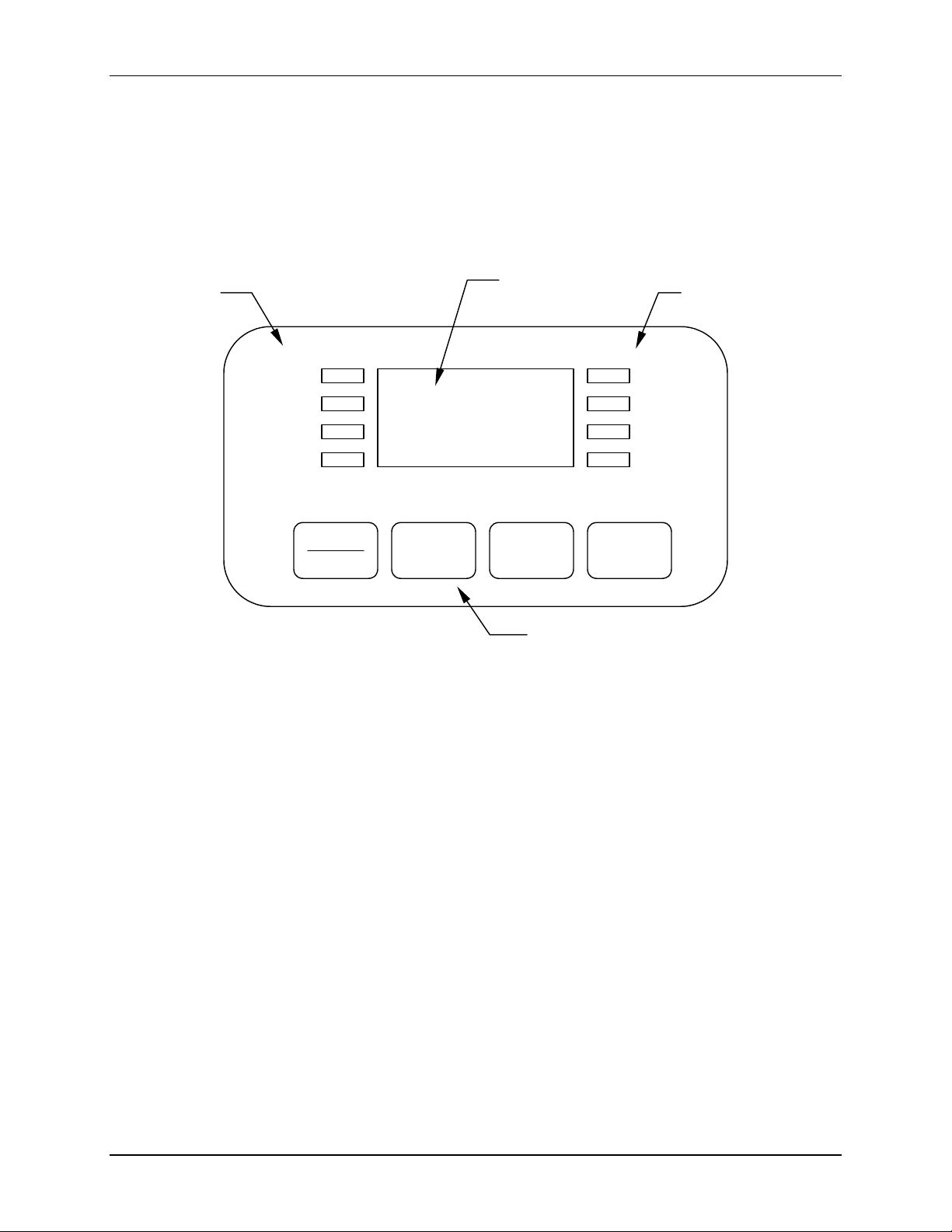
4.1 Keypad
STATUS
INDICATORS
MAINT
SET
TIME
MUTE
START
STOP
44
F
EEAATTUURREES
F
S
Figure 1: Keypad
LED DISPLAY
RPM
HRS
ºC
,
V
W
SELECT
FUNCTION
INDICATORS
LED DISPLAY
The digital display on the control panel is a three-digit
shaker operation the display will indicate:
• Shaker status (on/off)
• Shaking speed
• Chamber temperature
• Setpoints
• Hours remaining (timed run)
• Lid open
USER INTERFACE KEYS
•
START/STOP This key is used to start or stop the shaker. It will
also activate or stop the timer when a timed run is
desired.
•
SELECT This key is used to change the displayed parameter.
USER INTERFACE KEYS
LED DISPLAY. During normal
New Brunswick Scientific Co., Inc. User’s Guide
Artisan Technology Group - Quality Instrumentation ... Guaranteed | (888) 88-SOURCE | www.artisantg.com
Page 23

22
• V(UP), W(DOWN) These keys are used to adjust the setpoint of a
displayed parameter up or down. They also allow
the user to enter the
changes.
STATUS INDICATORS
Four status indicator lights are located to the left of the
•
MAINT Remains lit after 10,000 hours of use. Accumulated
running time is internally monitored and may be
displayed as a guideline.
•
SET Indicates that the shaker is in the SET MODE and
setpoints are being displayed and can be altered.
•
TIME Indicates that the timer is in operation. The shaker
can be programmed to run for a preset time from
0.1 hr. to 99.9 hrs. The timer can be disengaged
without stopping an ongoing run.
•
MUTE Indicates the status of the audible alarm. When
illuminated, the audible alarm is disabled.
FUNCTION INDICATORS
Four function indicator lights are located to the right of the
the current parameter being displayed.
•
RPM revolutions per minute
•
HOURS time remaining
•
°C interior chamber temperature
•
, not applicable
SET MODE for setpoint
LED DISPLAY. They are:
LED DISPLAY. They indicate
4.2 Platform Assemblies
The C-25 and C-25KC can be used with a wide variety of NBS 18 x 30 inch (46 x
76 cm)
A platform is a separate item that is required for operation. See Section 9,
Replacement Parts & Accessories, for details.
M1246-0051 YC-25 & C-25KC Classic Incubator Shakers User’s Guide
Artisan Technology Group - Quality Instrumentation ... Guaranteed | (888) 88-SOURCE | www.artisantg.com
platforms, which will accept a variety of clamps for flasks test tubes, etc.
Page 24
23
5.1 Installation of Platform
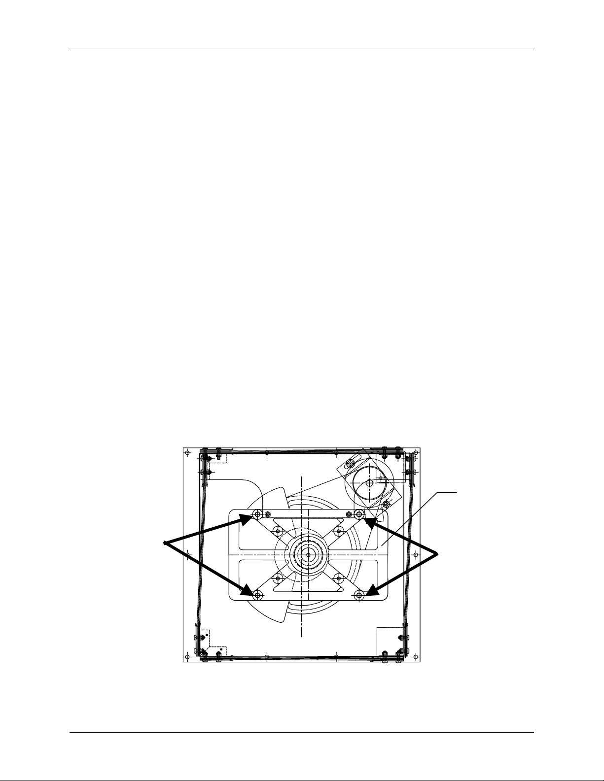
A platform must be installed on the unit prior to use.
The unit is shipped with the four Allen (hexagonal, countersunk) head platform screws
installed in the subplatform of the bearing housing. These screws must be removed
before installing a platform. The Allen (“hex”) wrench is provided.
#NOTE:
There are two small plastic straps holding the bearing housing in place
during shipping. The straps must be removed from the unit
1. Using the 7/32-inch hex wrench provided, remove the four Allen head platform
screws from the sub-platform.
2. Place the platform on the
with the platform screw locations in the
3. Insert the four platform screws (Allen head) provided and tighten them with the 7/32inch hex wrench provided to secure platform.
Figure 2: Platform Screw Locations
55
SUBPLATFORM. Align the mounting holes of the platform
G
EETTTTIINNGG
G
SUBPLATFORM.
S
TTAARRTTEED
S
D
SUBPLATFORM
New Brunswick Scientific Co., Inc. User’s Guide
Artisan Technology Group - Quality Instrumentation ... Guaranteed | (888) 88-SOURCE | www.artisantg.com
Page 25
24
5.2 Installing Flask Clamps
Flask clamps purchased for use with universal platforms (see Section 9.2)
require installation. Clamps are installed by securing the base of the clamp
to the platform with the correct type and number of screws. All clamps are
shipped complete with hardware.
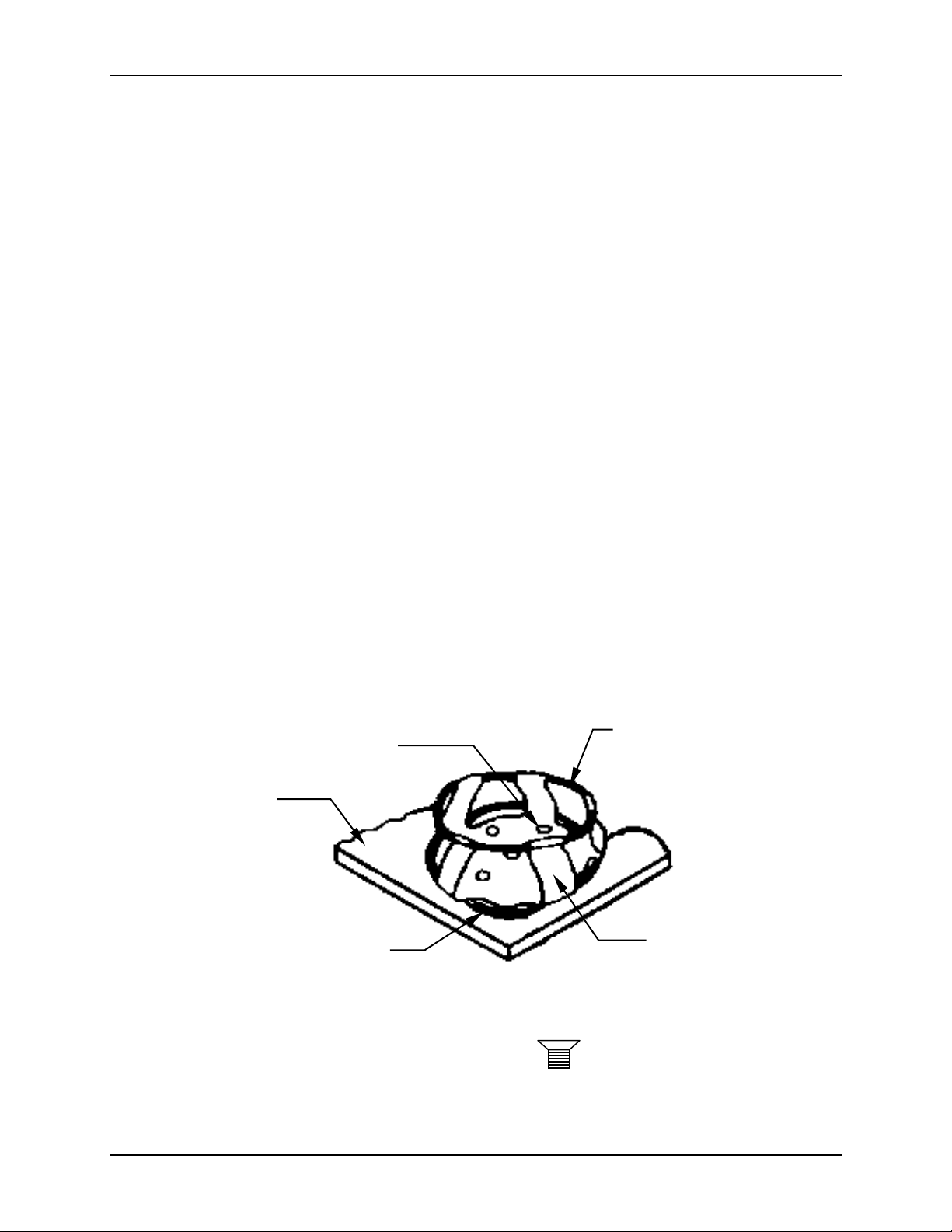
Clamps for 2-, 2.8- and 4-liter flasks are shipped with an additional girdle to keep the
flasks in place. The girdle is an assembly of springs and sections of rubber tubing. One
girdle is already in place on the clamp, the other is packed separately. To install these
double girdle clamps:
1. Place the clamp on the platform, aligning its mounting holes with holes on the platform.
Secure the clamp in place using the flat Phillips head screws provided (#S2116-3051,
10-24 x 5/16-inch). Use Figure 3b to help you identify the proper screws, as three
different types of screws are shipped with the clamps.
2. With the first girdle in place, as delivered, on the upper part of the clamp body (see
Figure 3a), insert an empty flask into the clamp.
3. After making sure the sections of tubing are located between the clamp legs, roll the first
girdle down the legs of the clamp as far as it can go. The tubing sections will rest against
the platform, and the springs will be under the clamp base.
4. Place the second girdle around the upper portion of clamp body (just as the first girdle
was initially). Make sure that its spring sections rest against the clamp legs, while its
rubber tubing sections sit against the flask, in between the clamp legs.
Figure 3a: Double Girdle Clamp Installation
CLAMP
MOUNTING
HOLES (5)
UPPER GIRDLE
WITH GIRDLE
TUBES
PLATFORM
LOWER
GIRDLE WITH
GIRDLE TUBES
CLAMP BODY
(LEGS AND BASE)
Figure 3b: Clamp Fastener
9
M1246-0051 YC-25 & C-25KC Classic Incubator Shakers User’s Guide
Artisan Technology Group - Quality Instrumentation ... Guaranteed | (888) 88-SOURCE | www.artisantg.com
Page 26
25
#NOTE:
The upper girdle secures the flask within the clamp, and the bottom girdle
keeps the flask from spinning.
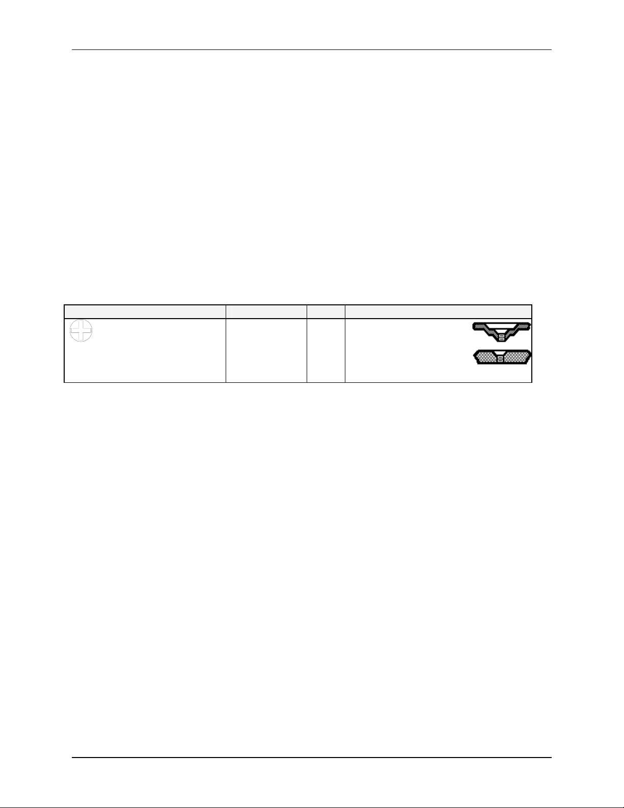
NBS flask clamps are used on a variety of shaker platforms. Flat head screws of different
lengths and thread pitch are used to secure the clamp, and all types are provided when
you purchase clamps. To identify the proper screw for your shaker application by
reference to the head style, consult Table 1 below, find the proper screws and set the
others aside:
Table 1: Clamp Hardware Application Chart
No matter what size the clamp, use these screws to fasten them to your platform:
Description Part Number Qty. Application
10-24 x 5/16 (7.9 mm) flat
Phillips (+) head screw
S2116-3051 1 5/16" (7.9 mm) thick
aluminum, phenolic and
stainless steel
platforms.
5.3 Electrical Connections
Before making electrical connections, verify that the power source voltage matches the
voltage on the
OFF position. The ELECTRICAL SPECIFICATION PLATE is located on the side panel of
the unit near the
CONNECTOR
ELECTRICAL SPECIFICATION PLATE and the ON/OFF SWITCH is on the
ON/OFF SWITCH. Connect the POWER CORD to the POWER
and the other end to a suitable, grounded receptacle.
New Brunswick Scientific Co., Inc. User’s Guide
Artisan Technology Group - Quality Instrumentation ... Guaranteed | (888) 88-SOURCE | www.artisantg.com
Page 27
26
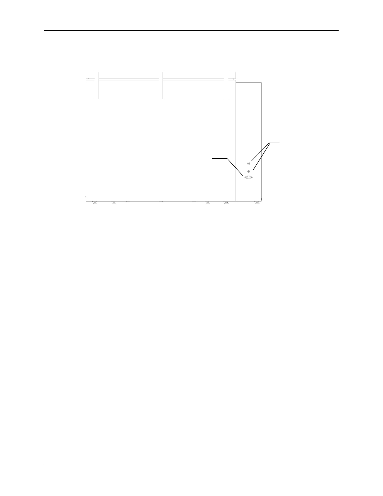
Figure 4: C-25 and C-25KC Rear Panel
CONNECTOR
POWER
FUSE
HOLDERS
M1246-0051 YC-25 & C-25KC Classic Incubator Shakers User’s Guide
Artisan Technology Group - Quality Instrumentation ... Guaranteed | (888) 88-SOURCE | www.artisantg.com
Page 28
27
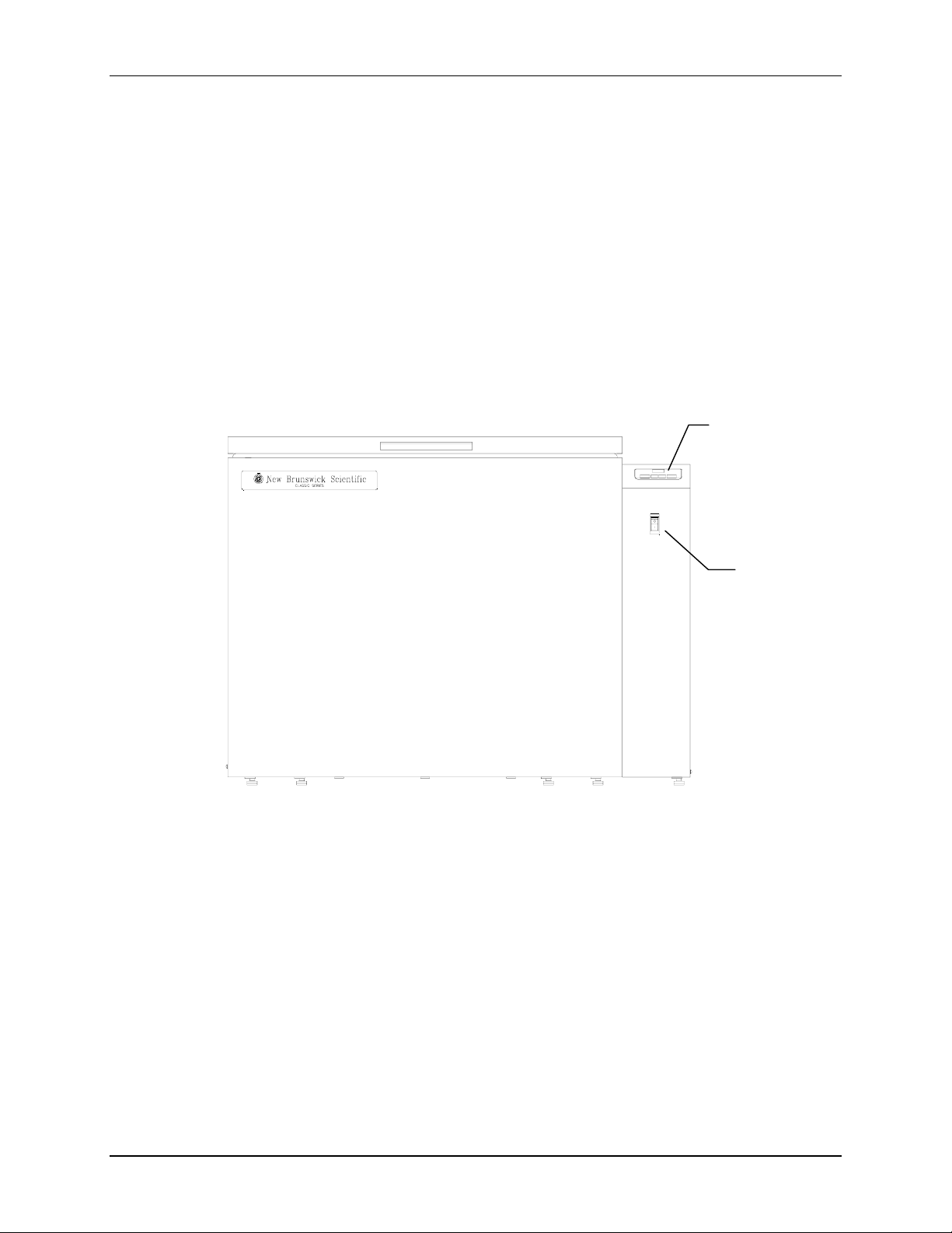
6.1 Starting the Shaker
To initially start the shaker, close the lid and turn the
of shaker to the
the speed as it accelerates to the last entered setpoint. The shaking action may be stopped
or started by pressing the
ON position. If the shaker begins to operate, the LED DISPLAY will track
Figure 5: C-25 and C-25KC Front Panel
START/STOP KEY.
66
ON/OFF SWITCH on the front panel
O
PPEERRAATTIIOON
O
KEYPAD
ON/OFF
SWITCH
N
#NOTE:
The shaker will not operate if the lid is open. This is indicated by the word
“lid” appearing in the LED DISPLAY.
New Brunswick Scientific Co., Inc. User’s Guide
Artisan Technology Group - Quality Instrumentation ... Guaranteed | (888) 88-SOURCE | www.artisantg.com
Page 29
28
6.2 Continuous (Unlimited) Run
1. Press
2. If the display indicates that the shaker is
3. Press either V or W KEY to enter SET MODE (the SET INDICATOR will illuminate).
4. Set the speed by using the V or
SELECT until the RPM INDICATOR is illuminated.
W KEY until the desired setpoint is displayed.
Holding the V or
W KEY will cause the setting to change more rapidly.
#NOTE:
The setpoint may be changed during a run without stopping the shaker by
following steps 2-4 above. During speed changes, a visual alarm (flashing
RPM INDICATOR) will flash and an audible alarm will sound until the speed
returns to within 5 rpm of the setpoint.
6.3 Checking a Setpoint
OFF, press the START/STOP KEY.
1. Press
2. Press either V or
SELECT until the desired indicator is illuminated.
CAUTION!
Holding the V or W key for more than 0.5 seconds causes the
speed setpoint to change. Should this occur, resetting will be
necessary.
6.4 Timed Functions
The shaker may be programmed to automatically stop after a preset time period of 0.1
hour - 99.9 hours. There must be power to the shaker in order to set the timer. However,
a timed run can be initiated while the unit is either shaking or stopped.
To set the timer:
1. Press the
2. Press either V or
3. While the
time (and start the run). The
duration of the run. At the end of the timed run the display will read
INDICATOR
SELECT KEY until the HRS INDICATOR is illuminated.
SET INDICATOR is illuminated, press the START/STOP KEY to program the
will flash and the audible alarm will “beep”.
W KEY to enter the SET MODE and display the current setpoint.
W KEY to enter the SET MODE and set between 0.1 - 99.9 hours.
TIME INDICATOR will light and remain on for the
OFF, the TIME
M1246-0051 YC-25 & C-25KC Classic Incubator Shakers User’s Guide
Artisan Technology Group - Quality Instrumentation ... Guaranteed | (888) 88-SOURCE | www.artisantg.com
Page 30

29
To disable the visual alarm (flashing TIME INDICATOR), press the SELECT KEY and
change to any other function.
To cancel the timer without stopping the shaker:
Repeat steps 1 and 2. Then immediately press the
INDICATOR
will cease to flash and the display will read OFF.
START/STOP KEY. The TIME
6.5 Alarm Functions
The C-25 and C-25KC shakers have an audible alarm which is activated at predetermined
times. To deactivate the alarm:
1. Press
2. Simultaneously press the V and
SELECT until the HRS INDICATOR is illuminated.
W KEYS. The SET and MAINT INDICATORS will
flash.
3. While the
SET and MAINT INDICATORS are flashing press the START/STOP KEY.
The alarm may be reactivated by repeating steps 1-3. The
MUTE INDICATOR will
illuminate.
6.6 Temperature Setpoint
Press the
SELECT KEY until the function °C INDICATOR illuminates. The temperature can
be set from 7°C above (for C-25) and 15°C below (for C-25KC) the current ambient
temperature up to 60.0°C. Increasing or decreasing the setpoint is accomplished with the
V or
W KEY.
During operation, if the temperature of the chamber is more than 1.0°C higher or lower
than the temperature setpoint, an alarm is triggered. This alarm consists of a flashing
INDICATOR
and audible beep. The alarm will automatically deactivate as the unit
achieves the set temperature.
If desired, the temperature control system of the C-25KC may be shut off during set-up
for special investigations.
1. To deactivate the temperature control system press and hold the W
setpoint is at 4.0°C.
2. Holding the W
KEY, press the START / STOP KEY.
3. The temperature setpoint display shows
refrigeration system will be activated.
4. To reactivate the temperature controller, press the V
temperature setpoint is displayed.
°C
KEY until the
OFF and neither the heater nor the
KEY until the desired
New Brunswick Scientific Co., Inc. User’s Guide
Artisan Technology Group - Quality Instrumentation ... Guaranteed | (888) 88-SOURCE | www.artisantg.com
Page 31

30
6.7 Total Running Time
The control modules of the C-25 and C-25KC shaker totalize the time the shaker has
been “
ON” to track hours of usage. To display the accumulated running time:
1. Press
SELECT until the HRS INDICATOR is illuminated.
2. Simultaneously press the V and W
The
SET and MAINT INDICATORS will flash and the accumulated running time will be
displayed in hundreds of hours (i.e., “02” equals 200 hours; “102” equals 10,200 hours).
This display will continue for 10 seconds and then default to the previous mode readout.
6.8 Maint Indicator
After 10,000 hours of operation, the
maintenance is recommended at this point.
To deactivate the
MAINT INDICATOR:
1. Press
SELECT until the HRS INDICATOR is illuminated.
2. Simultaneously press the V and W
3. Press the W
KEY.
KEYS.
MAINT INDICATOR will illuminate. Preventive
KEYS.
6.9 Power Failure
In the event of a power failure, the C-25 and C-25KC shakers are equipped with an
automatic restart function.
If the shaker was in operation prior to the power interruption, the shaker will begin to
operate at its last entered setpoint. The
failure has occurred. Press any key to cease the flashing in the display.
LED DISPLAY will flash indicating that a power
M1246-0051 YC-25 & C-25KC Classic Incubator Shakers User’s Guide
Artisan Technology Group - Quality Instrumentation ... Guaranteed | (888) 88-SOURCE | www.artisantg.com
Page 32
31
77
WARNING!
Always turn off the shaker and disconnect the power cord from
the power supply BEFORE performing any maintenance on the
unit.
7.1 Cleaning External Surfaces
The unit may be cleaned using a damp cloth or any standard, household or laboratory
cleaner to wipe down its outer surfaces. Do not use abrasive or corrosive compounds to
clean this instrument, as they may damage the unit and void the warranty.
7.2 Fuse Replacement
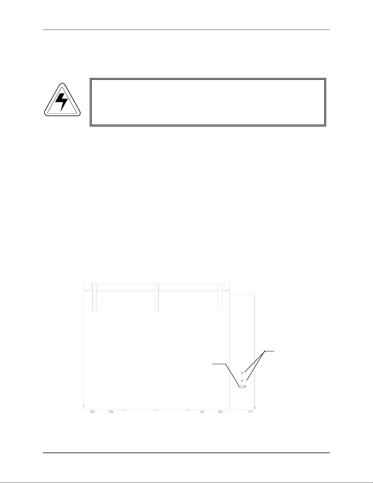
The C-25 and C-25KC require two electrical fuses. They are housed in the fuse holders
located on rear panel of the unit near the
repeated below):
Figure 4: C-25 and C-25KC Rear Panel
P
P
RREEVVEENNTTIIVVEE
POWER CORD CONNECTOR (see Figure 4,
M
M
AAIINNTTEENNAANNCCE
E
FUSE
POWER
CONNECTOR
New Brunswick Scientific Co., Inc. User’s Guide
Artisan Technology Group - Quality Instrumentation ... Guaranteed | (888) 88-SOURCE | www.artisantg.com
HOLDERS
Page 33

32
To check or replace a fuse:
1. Set the
ON/OFF SWITCH to off and disconnect the POWER CORD from the power
source.
2. Insert a small flat bladed screwdriver into the fuse holder groove and turn counter-
clockwise until it disengages and the fuse holder springs free.
Figure 6: Fuse Holder (detail)
3. Check the fuse and if it has failed, replace the fuse.
7.3 Belt Replacement
To replace the shaker’s drive belt:
1. Turn off the unit, and disconnect the power cord from the power source.
2. Open the lid.
3. Remove the platform, setting the platform and platform screws aside.
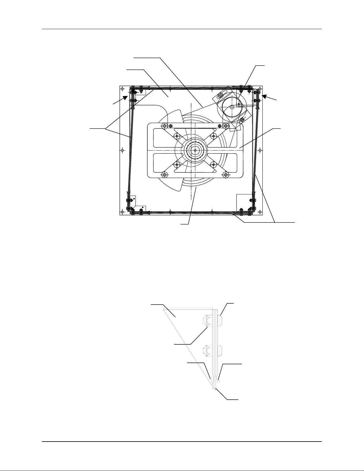
Refer to Figures 7 & 8 on the following page as you continue the procedure.
M1246-0051 YC-25 & C-25KC Classic Incubator Shakers User’s Guide
Artisan Technology Group - Quality Instrumentation ... Guaranteed | (888) 88-SOURCE | www.artisantg.com
Page 34
33
Y
Figure 7: Belt Removal
BELT
MOVER PLATE
DRIVE
PULLEY
HARDWARE
FLEXURES SUBPLATFORM
HARDWARE
BEARING HOUSING
PULLE
FLEXURES
4. Loosen and remove the hardware that attaches the
FLEXURES to the MOVER PLATE
(see Figure 8 below):
Figure 8: Flexure Attaching Hardware
(Reverse View)
MOVER
PLATE
STUD (2)
LOCK NUT
(2)
RETAINER
RETAINER
5. Using your fingers, reach under the
falls off the
New Brunswick Scientific Co., Inc. User’s Guide
Artisan Technology Group - Quality Instrumentation ... Guaranteed | (888) 88-SOURCE | www.artisantg.com
DRIVE PULLEY. Remove the belt from the BEARING HOUSING PULLEY.
SUBPLATFORM and move the BELT so that it
FLEXURE
Page 35

34
6. Grab the belt from underneath the sub-platform, pull it forward and over one corner
of the subplatform. Repeat for the other corner until the belt clears the subplatform,
but is constrained by the mover plate.
7. Slide the belt to one of the unattached sides of the mover plate and pull it through the
opening.
8. Slide the belt to the other side of the mover plate, pull it through the opening, and
remove it from the unit.
9. Install the replacement belt in similar fashion.
10. Reattach the
FLEXURES to the MOVER PLATE.
11. Reinstall the platform if desired, and close the lid.
12. Reconnect the power cord to the unit.
M1246-0051 YC-25 & C-25KC Classic Incubator Shakers User’s Guide
Artisan Technology Group - Quality Instrumentation ... Guaranteed | (888) 88-SOURCE | www.artisantg.com
Page 36

35
88
If any problems occur with your shaker, do not attempt to perform any service on the unit
other than specified in this manual. Unauthorized servicing may void the warranty. Please
contact your local NBS Sales Order Department
In any correspondence with NBS, please refer to the Model Number and Serial Number of your
unit. This information is on the
of the unit near the
ON/OFF SWITCH.
ELECTRICAL SPECIFICATION PLATE, located on the side panel
T
RROOUUBBLLEESSHHOOOOTTIINNG
T
G
New Brunswick Scientific Co., Inc. User’s Guide
Artisan Technology Group - Quality Instrumentation ... Guaranteed | (888) 88-SOURCE | www.artisantg.com
Page 37

36
THIS PAGE IS INTENTIONALLY BLANK
M1246-0051 YC-25 & C-25KC Classic Incubator Shakers User’s Guide
Artisan Technology Group - Quality Instrumentation ... Guaranteed | (888) 88-SOURCE | www.artisantg.com
Page 38
37
99
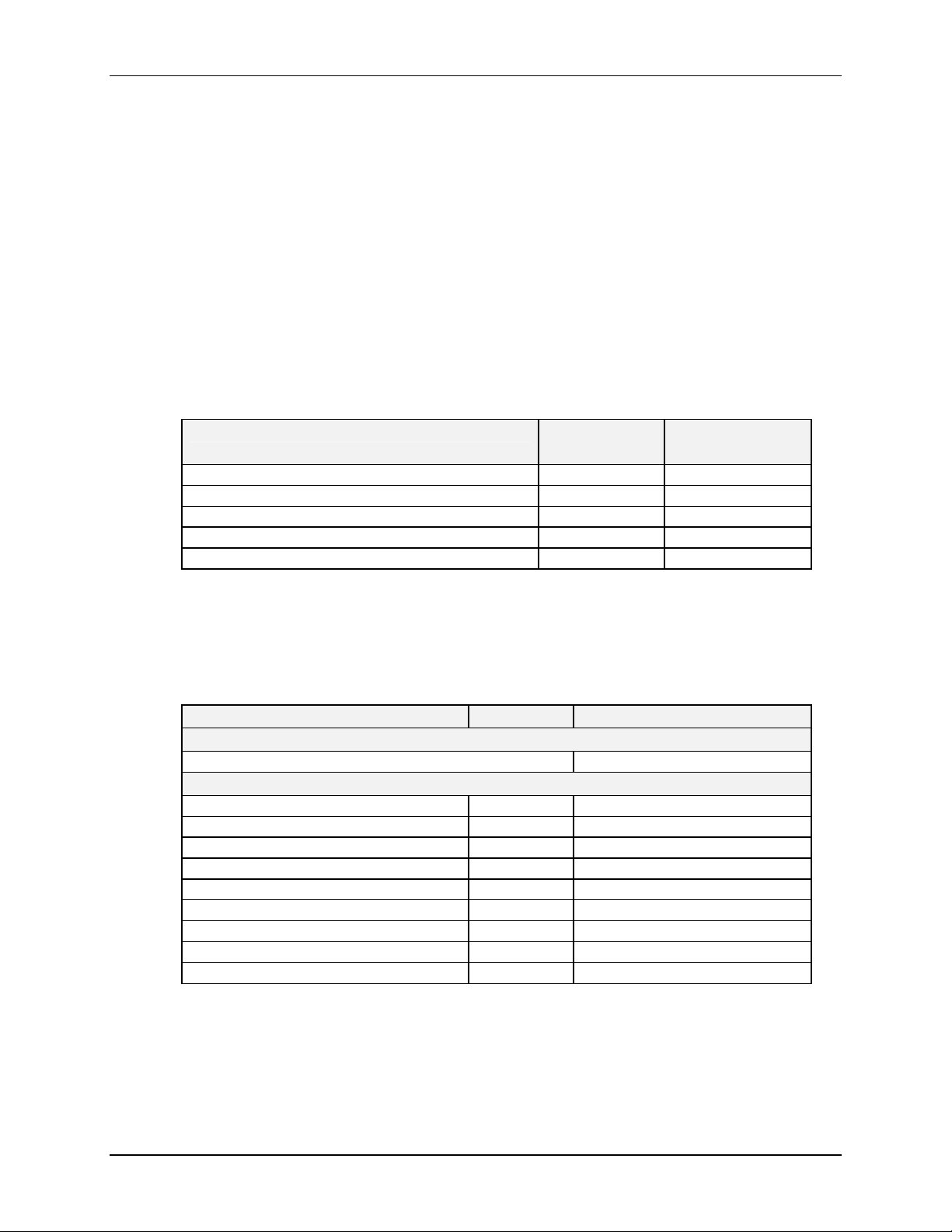
When ordering replacement or accessory parts, or requesting service information, please provide
the Model Number and Serial Number of your shaker. This information is on the
SPECIFICATION PLATE
9.1 Replacement Parts
V-Belt* 1 R-334
Housing Extractor Plate* 1 M1191-9300
3/8-16 NC x 1 ¼” long flat head Allen screw* 3 S1127-3206
Fuse, Slo Blo® 1.6 A, 250 V 1 P0380-3532
Fuse, Slo Blo® 0.16 A, 250 V 1 P0380-3710
*needed for belt replacement
, located on the side panel of the unit.
Table 2: Service Parts
Part Description Quantity
R
EEPPLLAACCEEMMEENNTT
R
A
A
Required
P
AARRTTSS
P
CCCCEESSSSOORRIIEES
ELECTRICAL
NBS Part
Number
&&
S
9.2 Accessories
Platform Description Capacity NBS Part Number
See Table 5 on the following page M1250-9920
50 ml Erlenmeyer Flasks 108 M1191-9908
125 ml Erlenmeyer Flasks 60 M1191-9909
250 ml Erlenmeyer Flasks 40 M1191-9910
500 ml Erlenmeyer Flasks 24 M1191-9911
1 L Erlenmeyer Flasks 15 AG-1
2 L Erlenmeyer Flasks 12 AG-2
2.8 L Fernbach Flasks 6 AG-28
4 L Erlenmeyer Flasks 6 AG-4
6 L Erlenmeyer Flasks 4 AG-6
Table 3: Platforms
Universal Platform
Dedicated Platforms
New Brunswick Scientific Co., Inc. User’s Guide
Artisan Technology Group - Quality Instrumentation ... Guaranteed | (888) 88-SOURCE | www.artisantg.com
Page 39

38
Table 4: Universal Platform Flask Capacity
Flask Type Capacity
50 ml Erlenmeyer Flasks 92
125 ml Erlenmeyer Flasks 39
250 ml Erlenmeyer Flasks 30
500 ml Erlenmeyer Flasks 18
1 L Erlenmeyer Flasks 12
2 L Erlenmeyer Flasks 8
2.8 L Fernbach Flasks 6
4 L Erlenmeyer Flasks 6
6 L Erlenmeyer Flasks 4
Table 5: Carriers & Test Tube Racks
Accessory Description NBS Part Number
Utility Tray with rubber mat for shaking 96 well plates, petri
dishes and other labware at low speeds.
Angled Test Tube Rack Holder for user-supplied test tube
racks that are 4-5 inches (10-13 mm) wide and up to 15 inches
(38 mm) long. Capacity: 4 racks/platform.
Angled Test Tube Rack Spacer for use with TTR-210 to
accommodate test tube racks that are less than 5 inches
(13 mm) wide and up to 15 inches (38 mm) long.
Microtiter Plate Carrier, capacity up to 4 microtiter plates TTR-221*
80-tube (8-11mm ∅) Adjustable Angle Test Tube Rack M1289-0100a
60-tube (12-15mm ∅) Adjustable Angle Test Tube Rack M1289-0200a
42-tube (15-18mm ∅) Adjustable Angle Test Tube Rack M1289-0300a
30-tube (18-21mm ∅) Adjustable Angle Test Tube Rack M1289-0400a
22-tube (22-26mm ∅) Adjustable Angle Test Tube Rack M1289-0500a
20-tube (26-30mm ∅) Adjustable Angle Test Tube Rack M1289-0600a
Microplate Holder, stack 3 deep-well or 9 standard microplates M1289-0700
*Universal Platform Required
a Platform capacity is 7 racks
Platform capacity is 16 racks
AG-00
TTR-210*
TTR-215*
M1246-0051 YC-25 & C-25KC Classic Incubator Shakers User’s Guide
Artisan Technology Group - Quality Instrumentation ... Guaranteed | (888) 88-SOURCE | www.artisantg.com
Page 40
39
D
1100 D
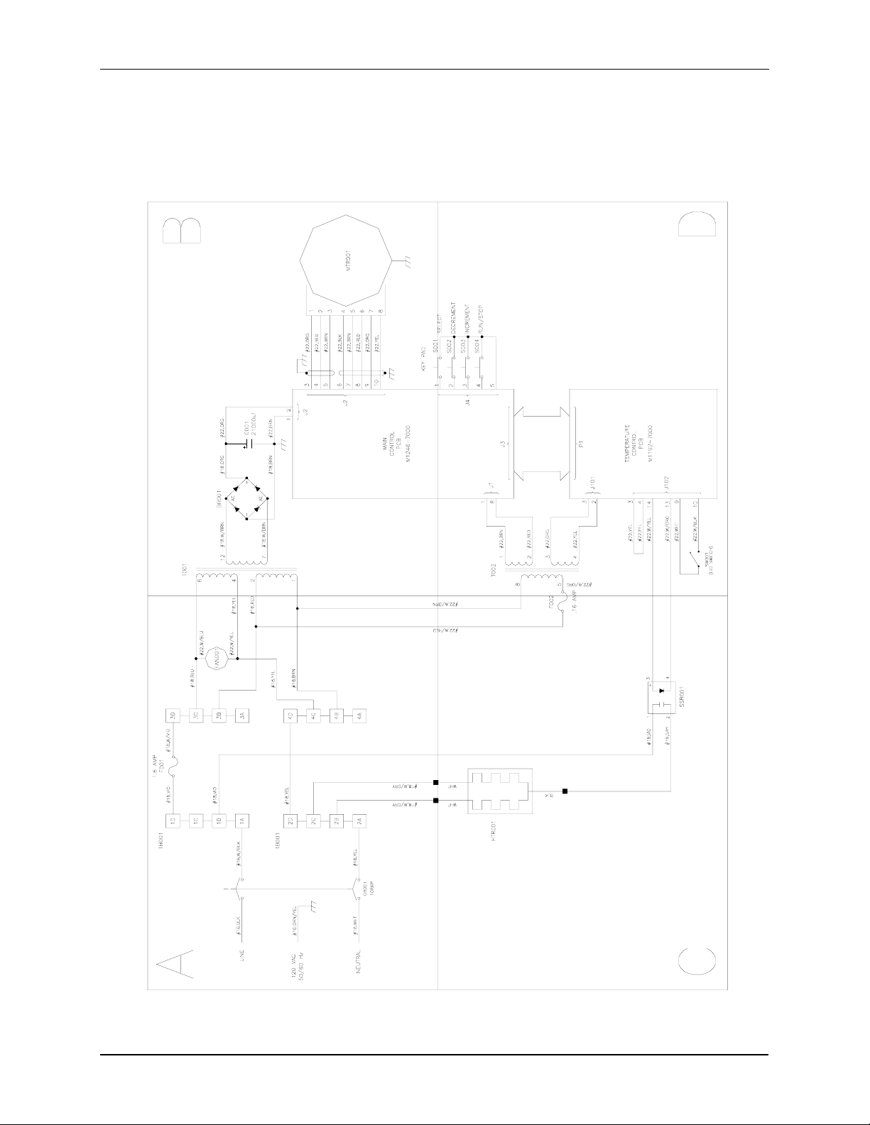
Figure 9: C-25 115 VAC Control Schematic (Overview)
RRAAW
WIINNGGSS
New Brunswick Scientific Co., Inc. User’s Guide
Artisan Technology Group - Quality Instrumentation ... Guaranteed | (888) 88-SOURCE | www.artisantg.com
Page 41
40
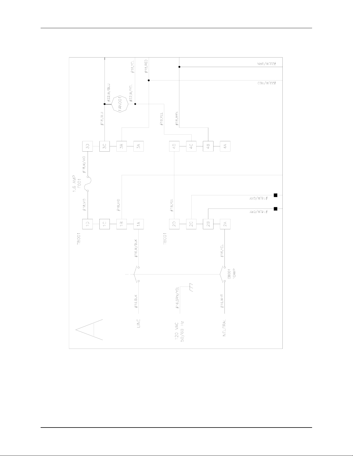
Figure 9a: C-25 115 VAC Control Schematic (Section A)
M1246-0051 YC-25 & C-25KC Classic Incubator Shakers User’s Guide
Artisan Technology Group - Quality Instrumentation ... Guaranteed | (888) 88-SOURCE | www.artisantg.com
Page 42
41
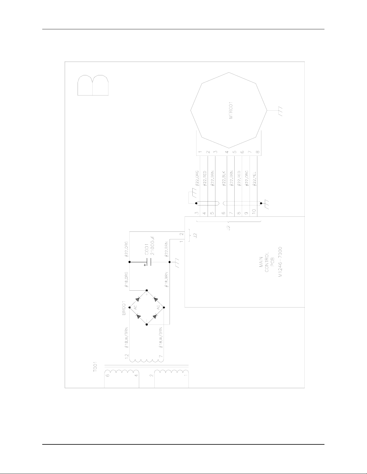
Figure 9b: C-25 115 VAC Control Schematic (Section B)
New Brunswick Scientific Co., Inc. User’s Guide
Artisan Technology Group - Quality Instrumentation ... Guaranteed | (888) 88-SOURCE | www.artisantg.com
Page 43
42
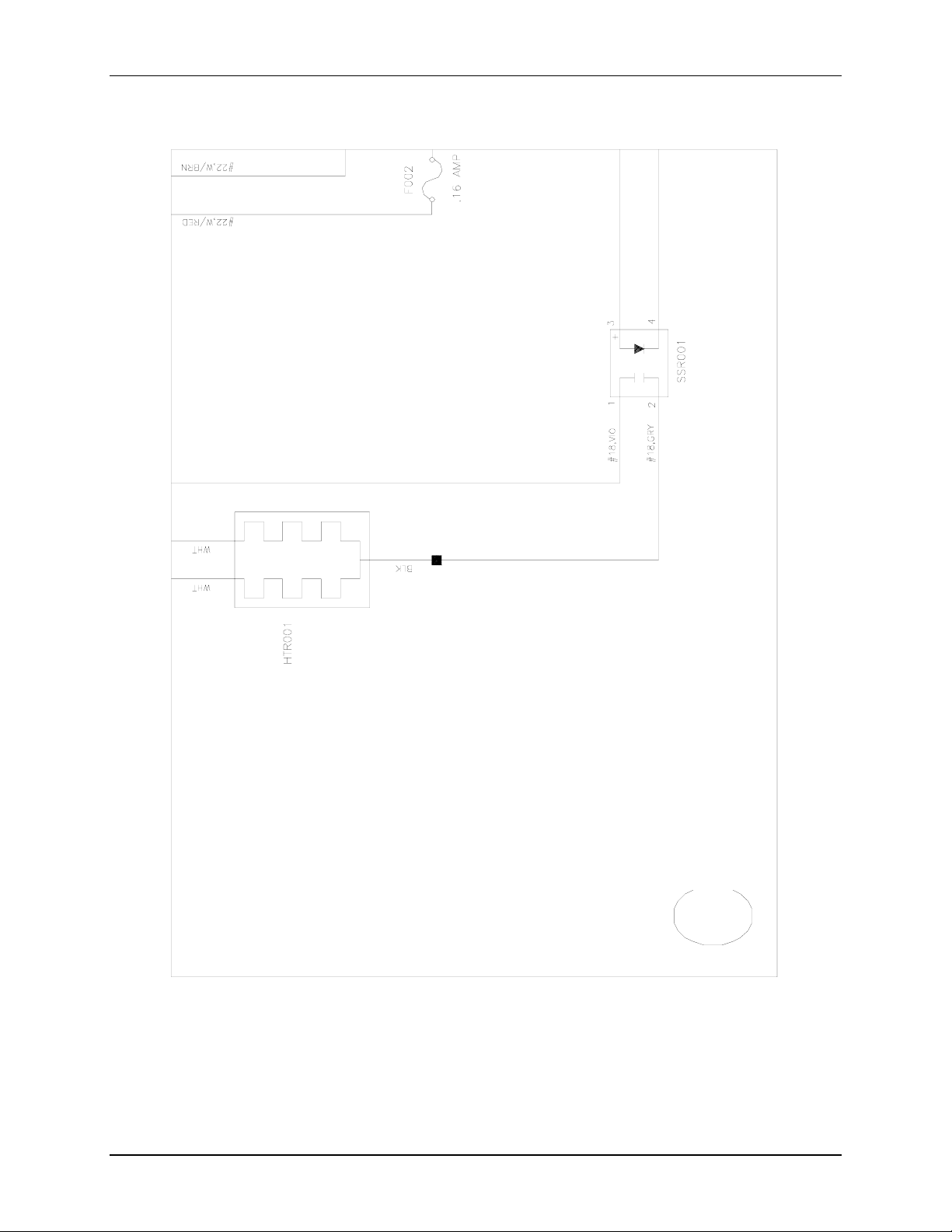
Figure 9c: C-25 115 VAC Control Schematic (Section C)
M1246-0051 YC-25 & C-25KC Classic Incubator Shakers User’s Guide
Artisan Technology Group - Quality Instrumentation ... Guaranteed | (888) 88-SOURCE | www.artisantg.com
Page 44
43
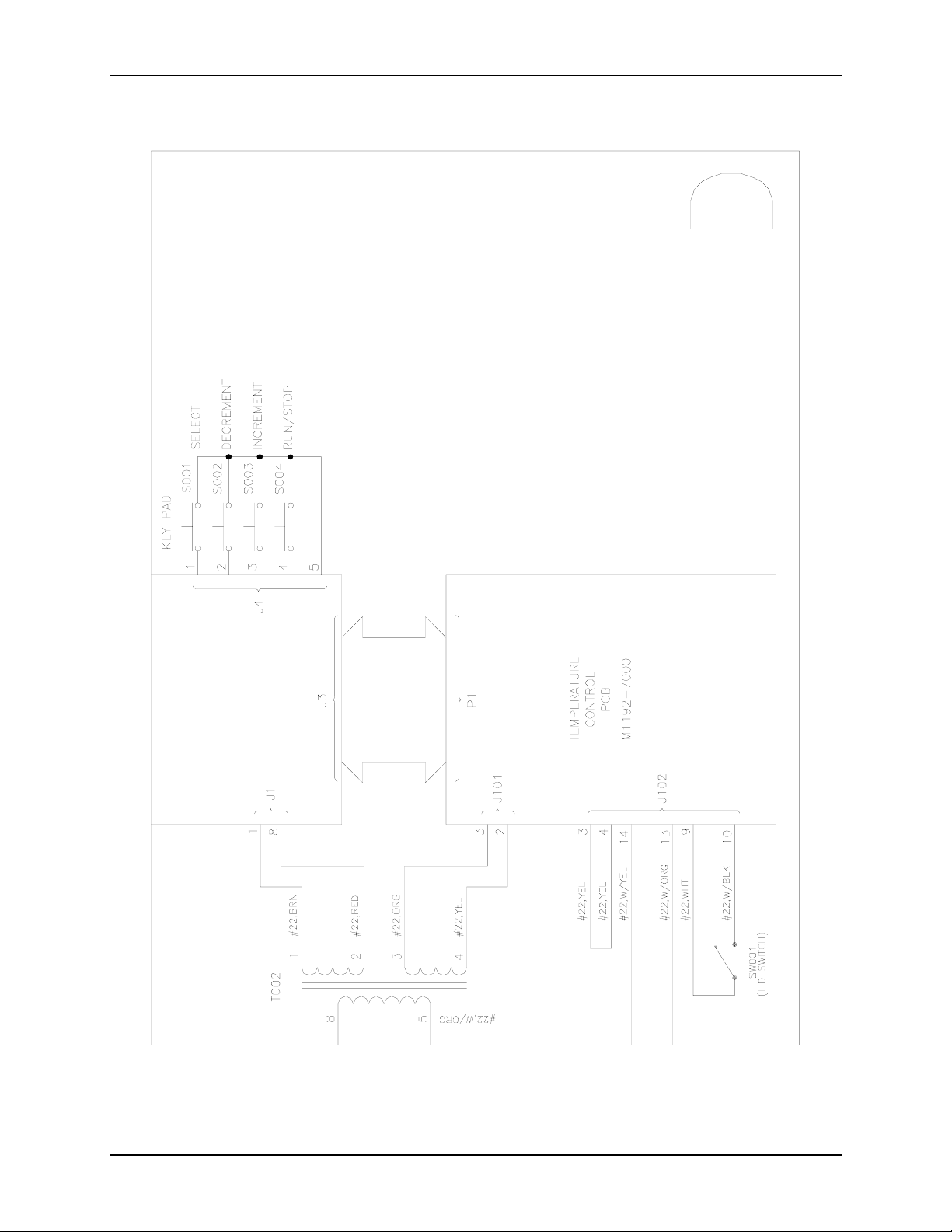
Figure 9d: C-25 115 VAC Control Schematic (Section D)
New Brunswick Scientific Co., Inc. User’s Guide
Artisan Technology Group - Quality Instrumentation ... Guaranteed | (888) 88-SOURCE | www.artisantg.com
Page 45
44
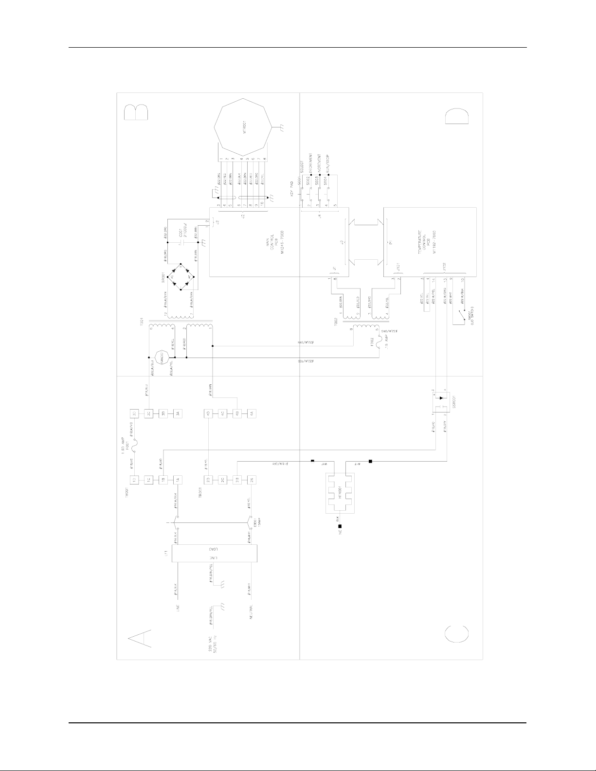
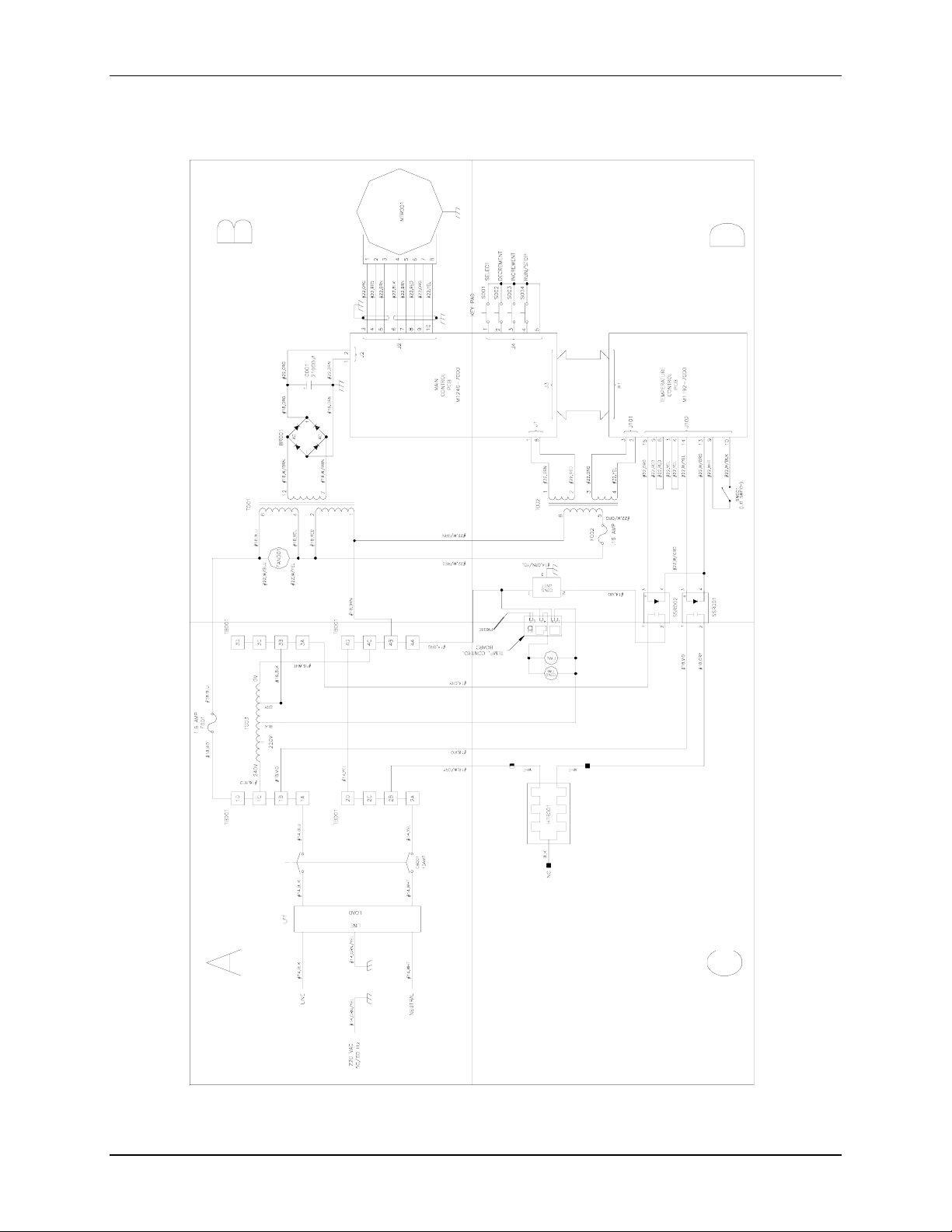
Figure 10: C-25 230 VAC Control Schematic (Overview)
M1246-0051 YC-25 & C-25KC Classic Incubator Shakers User’s Guide
Artisan Technology Group - Quality Instrumentation ... Guaranteed | (888) 88-SOURCE | www.artisantg.com
Page 46
45
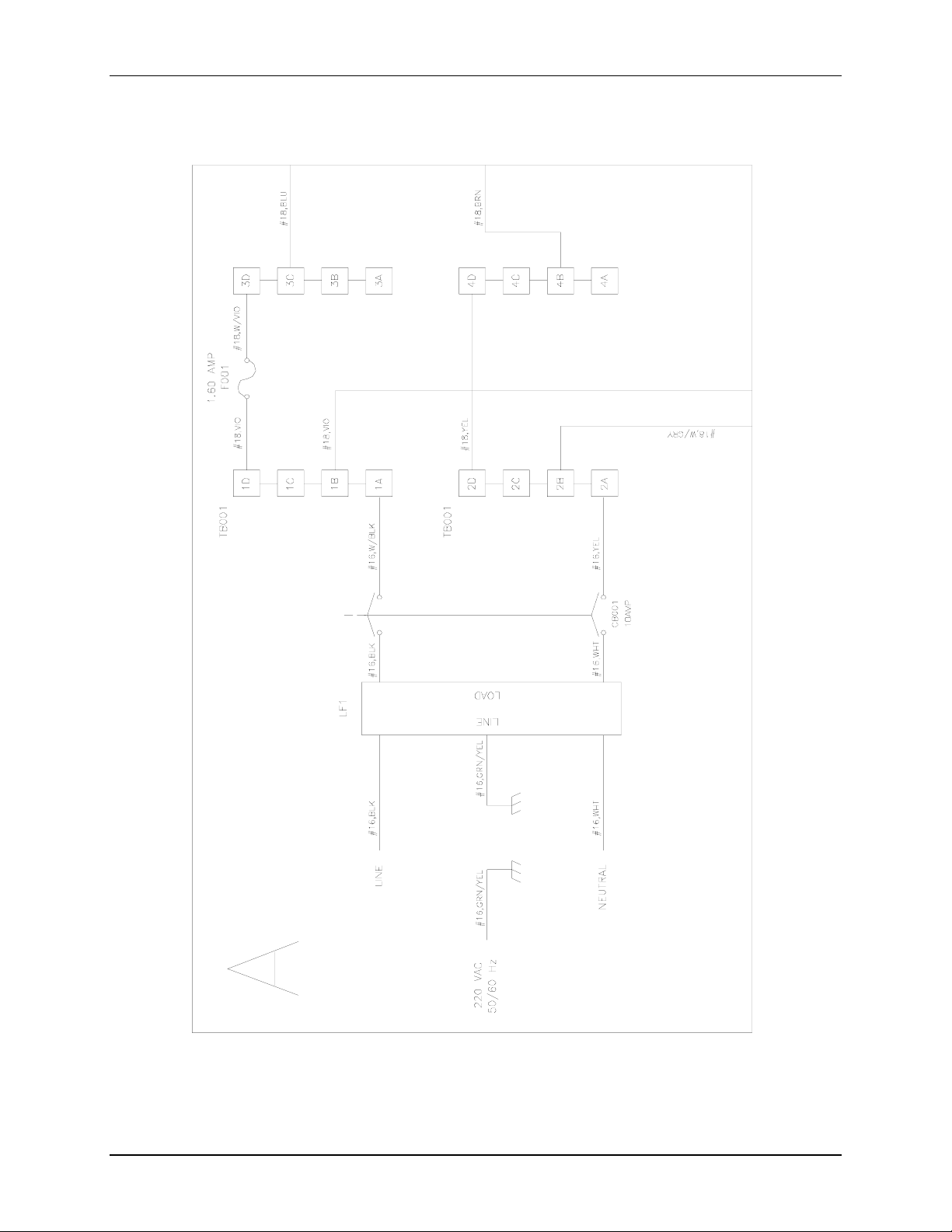
Figure 10a: C-25 230 VAC Control Schematic (Section A)
New Brunswick Scientific Co., Inc. User’s Guide
Artisan Technology Group - Quality Instrumentation ... Guaranteed | (888) 88-SOURCE | www.artisantg.com
Page 47
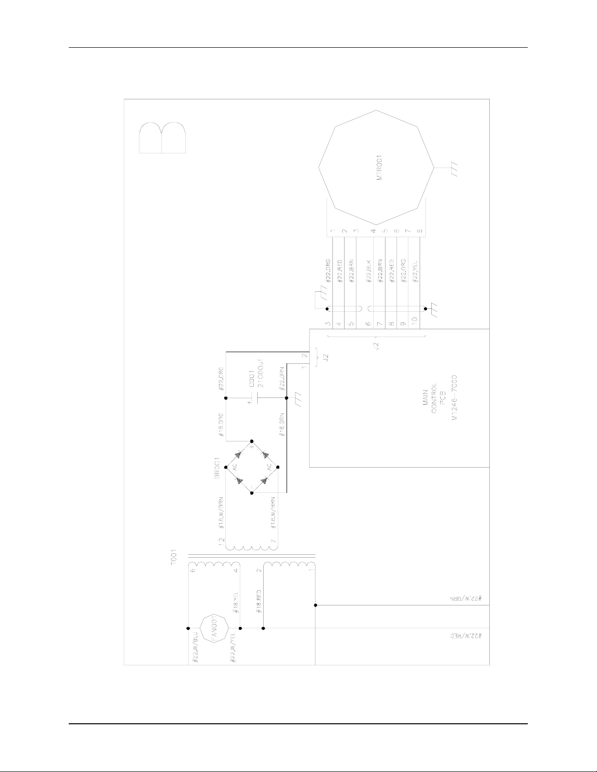
46
Figure 10b: C-25 230 VAC Control Schematic (Section B)
M1246-0051 YC-25 & C-25KC Classic Incubator Shakers User’s Guide
Artisan Technology Group - Quality Instrumentation ... Guaranteed | (888) 88-SOURCE | www.artisantg.com
Page 48
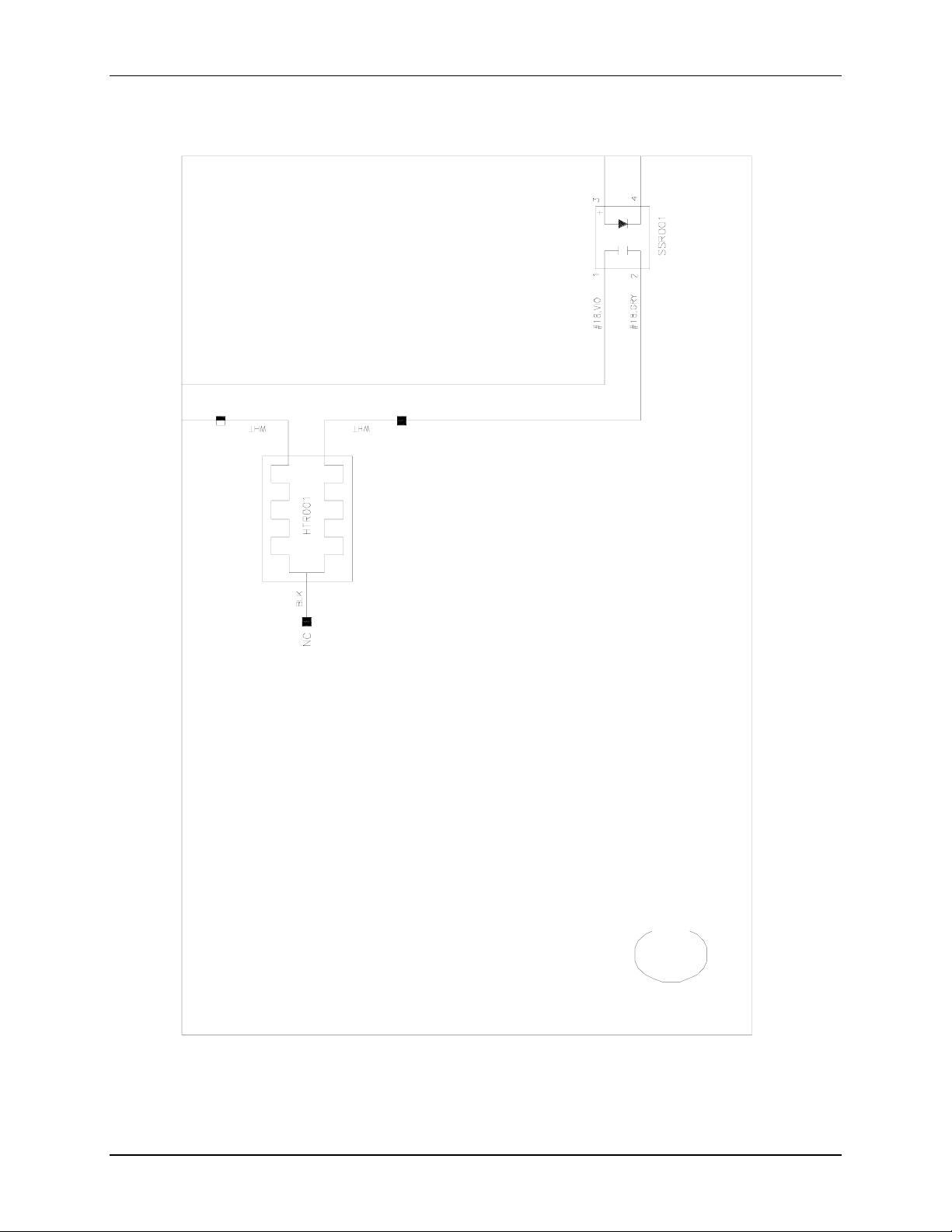
47
Figure 10c: C-25 230 VAC Control Schematic (Section C)
New Brunswick Scientific Co., Inc. User’s Guide
Artisan Technology Group - Quality Instrumentation ... Guaranteed | (888) 88-SOURCE | www.artisantg.com
Page 49
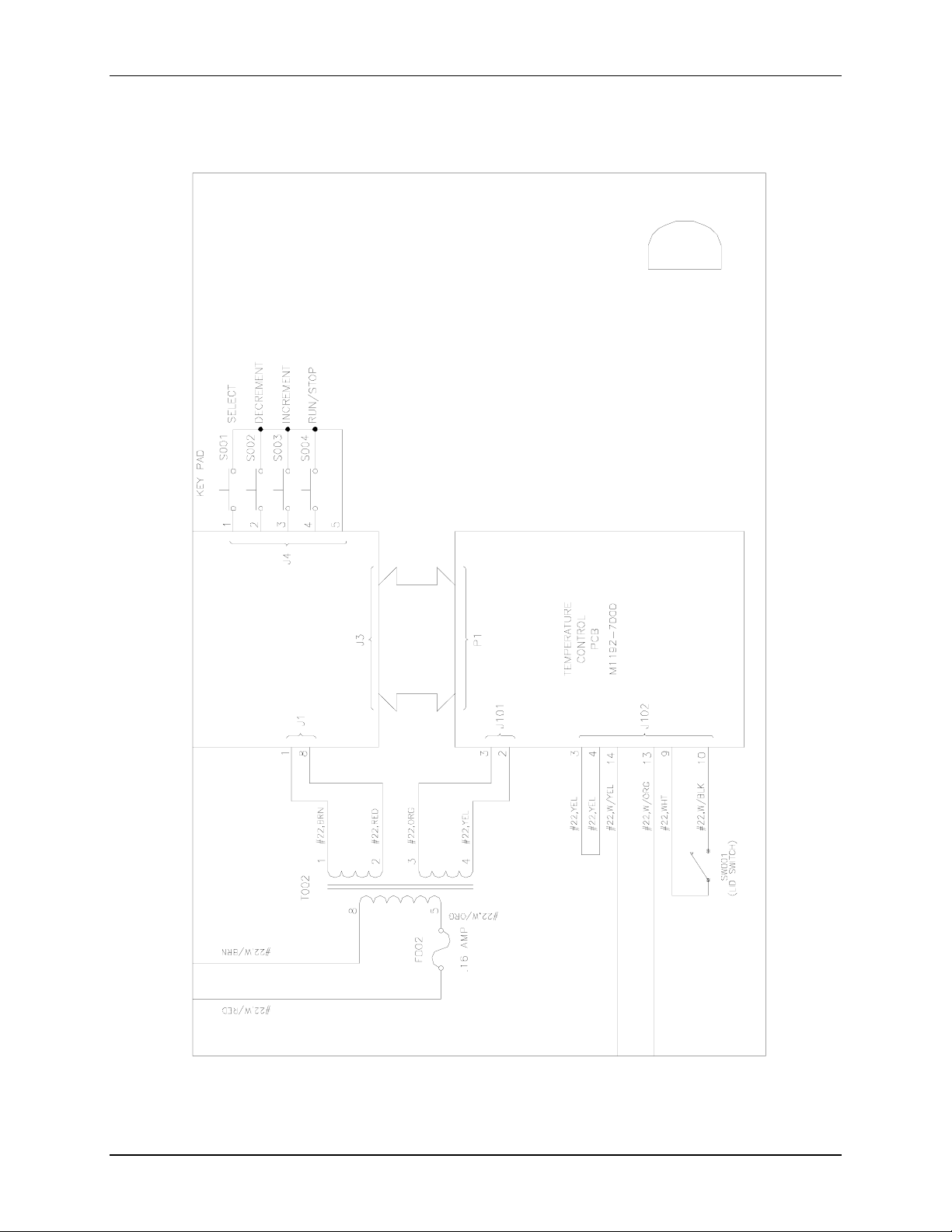
48
Figure 10d: C-25 230 VAC Control Schematic (Section D)
M1246-0051 YC-25 & C-25KC Classic Incubator Shakers User’s Guide
Artisan Technology Group - Quality Instrumentation ... Guaranteed | (888) 88-SOURCE | www.artisantg.com
Page 50
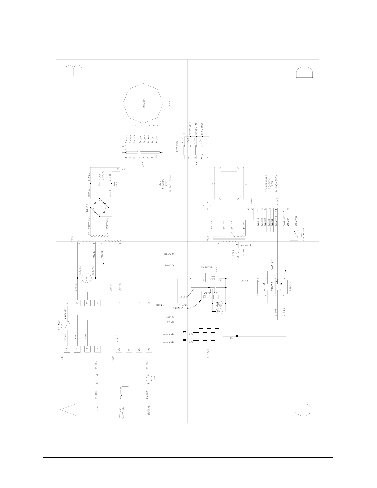
49
Figure 11: C-25KC 115 VAC Control Schematic (Overview )
New Brunswick Scientific Co., Inc. User’s Guide
Artisan Technology Group - Quality Instrumentation ... Guaranteed | (888) 88-SOURCE | www.artisantg.com
Page 51
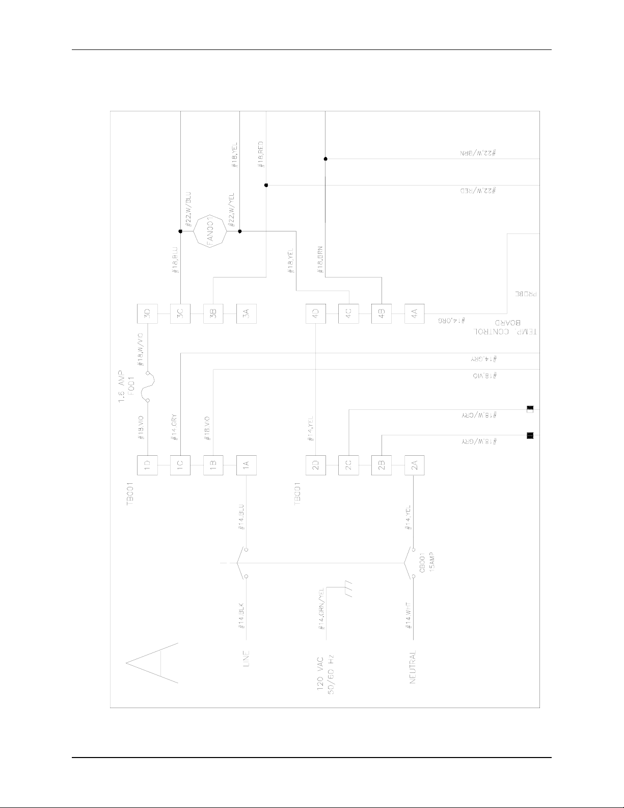
50
Figure 11a: C-25KC 115 VAC Control Schematic (Section A)
M1246-0051 YC-25 & C-25KC Classic Incubator Shakers User’s Guide
Artisan Technology Group - Quality Instrumentation ... Guaranteed | (888) 88-SOURCE | www.artisantg.com
Page 52
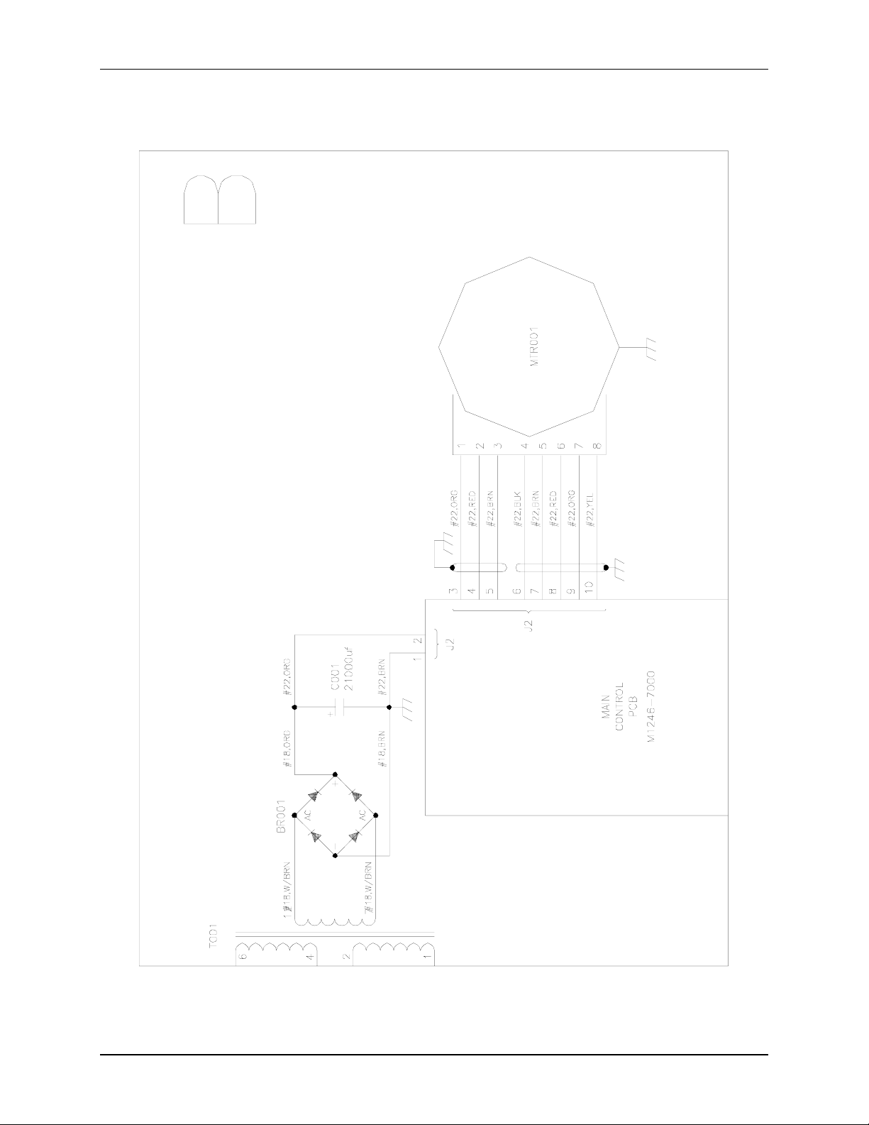
51
Figure 11b: C-25KC 115 VAC Control Schematic (Section B)
New Brunswick Scientific Co., Inc. User’s Guide
Artisan Technology Group - Quality Instrumentation ... Guaranteed | (888) 88-SOURCE | www.artisantg.com
Page 53
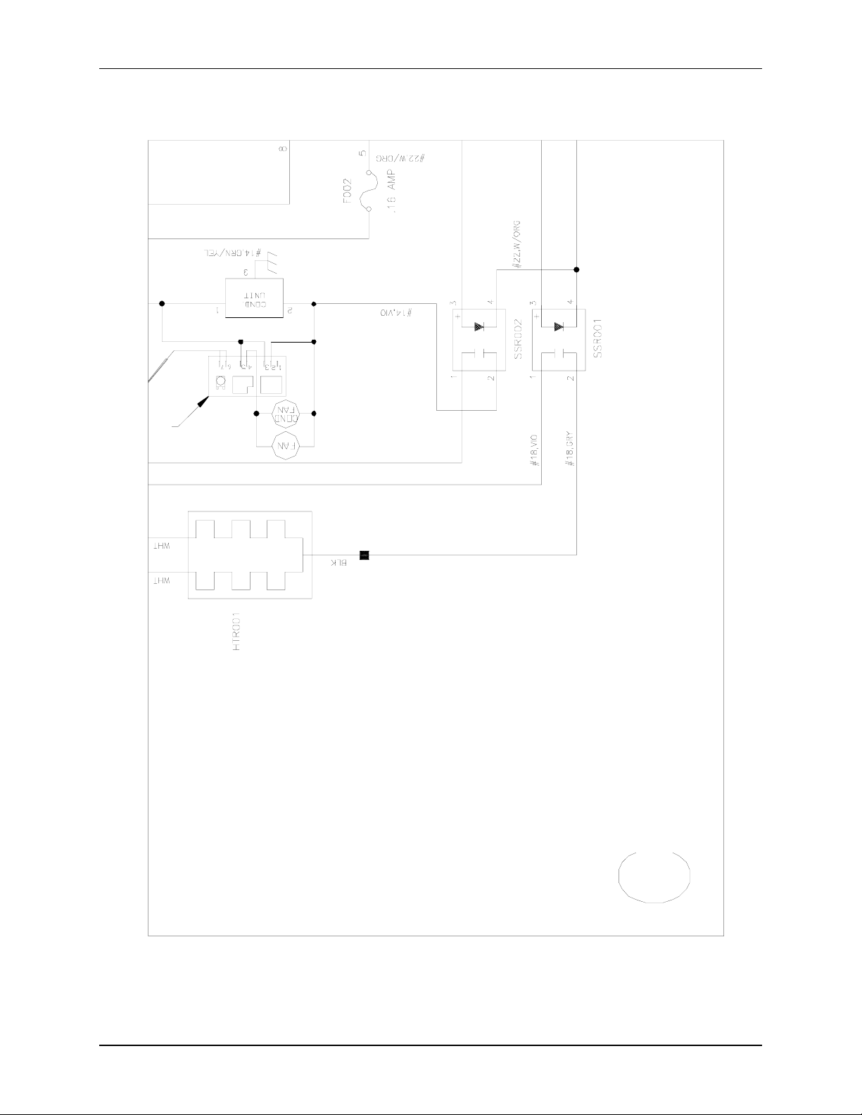
52
Figure 11c: C-25KC 115 VAC Control Schematic (Section C)
M1246-0051 YC-25 & C-25KC Classic Incubator Shakers User’s Guide
Artisan Technology Group - Quality Instrumentation ... Guaranteed | (888) 88-SOURCE | www.artisantg.com
Page 54
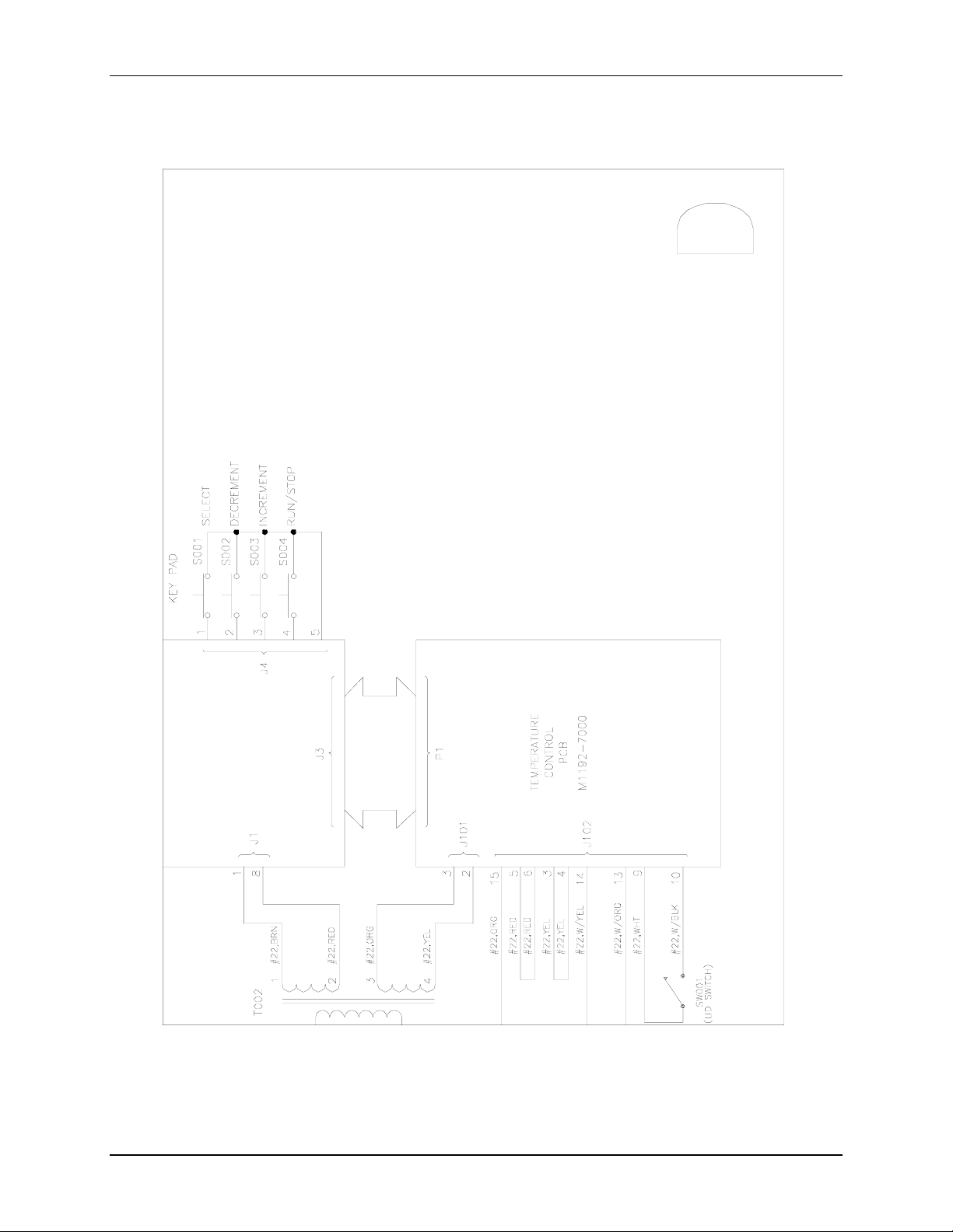
53
Figure 11d: C-25KC 115 VAC Control Schematic (Section D)
New Brunswick Scientific Co., Inc. User’s Guide
Artisan Technology Group - Quality Instrumentation ... Guaranteed | (888) 88-SOURCE | www.artisantg.com
Page 55
54
Figure 12: C-25KC 230 VAC Control Schematic (Overview)
M1246-0051 YC-25 & C-25KC Classic Incubator Shakers User’s Guide
Artisan Technology Group - Quality Instrumentation ... Guaranteed | (888) 88-SOURCE | www.artisantg.com
Page 56
55
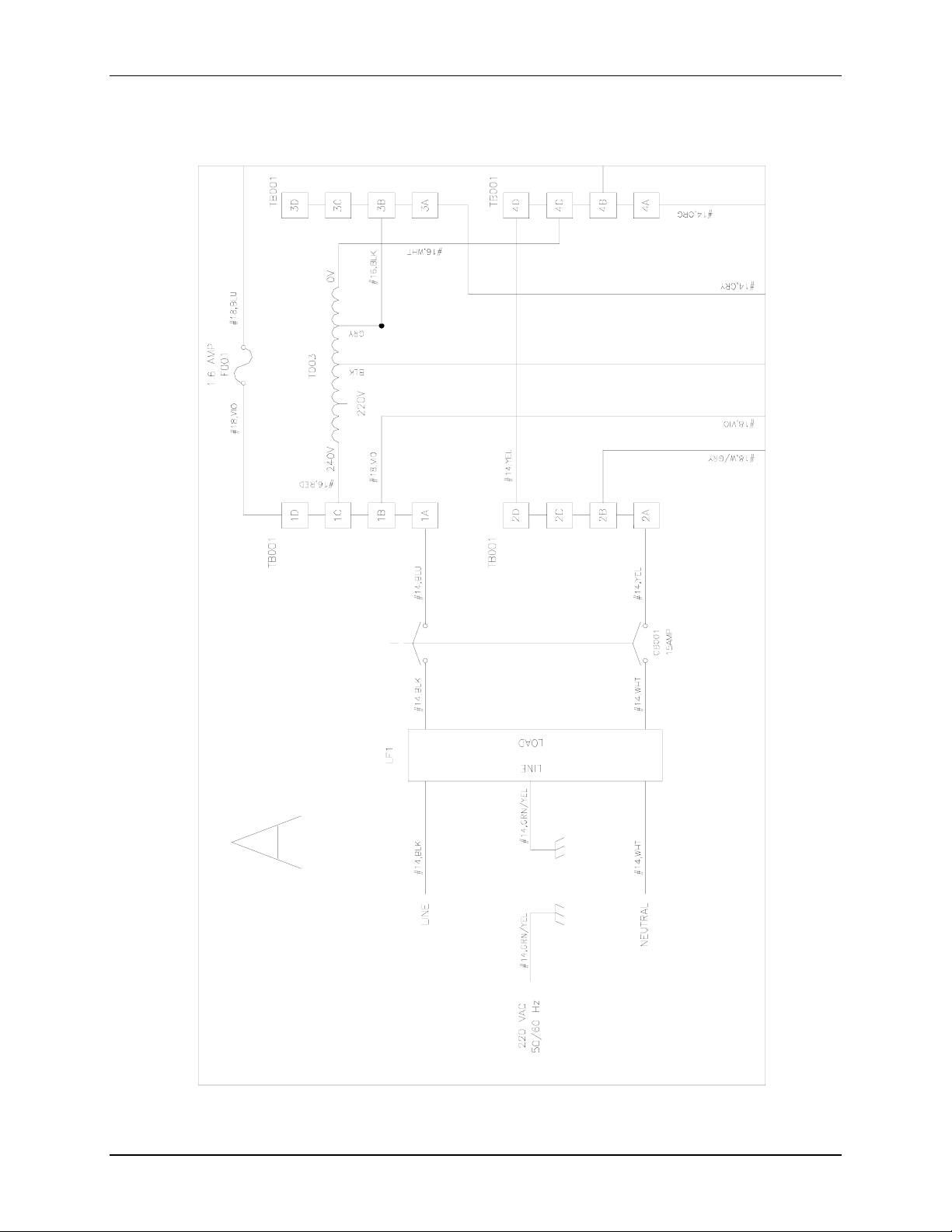
Figure 12a: C-25KC 230 VAC Control Schematic (Section A)
New Brunswick Scientific Co., Inc. User’s Guide
Artisan Technology Group - Quality Instrumentation ... Guaranteed | (888) 88-SOURCE | www.artisantg.com
Page 57
56
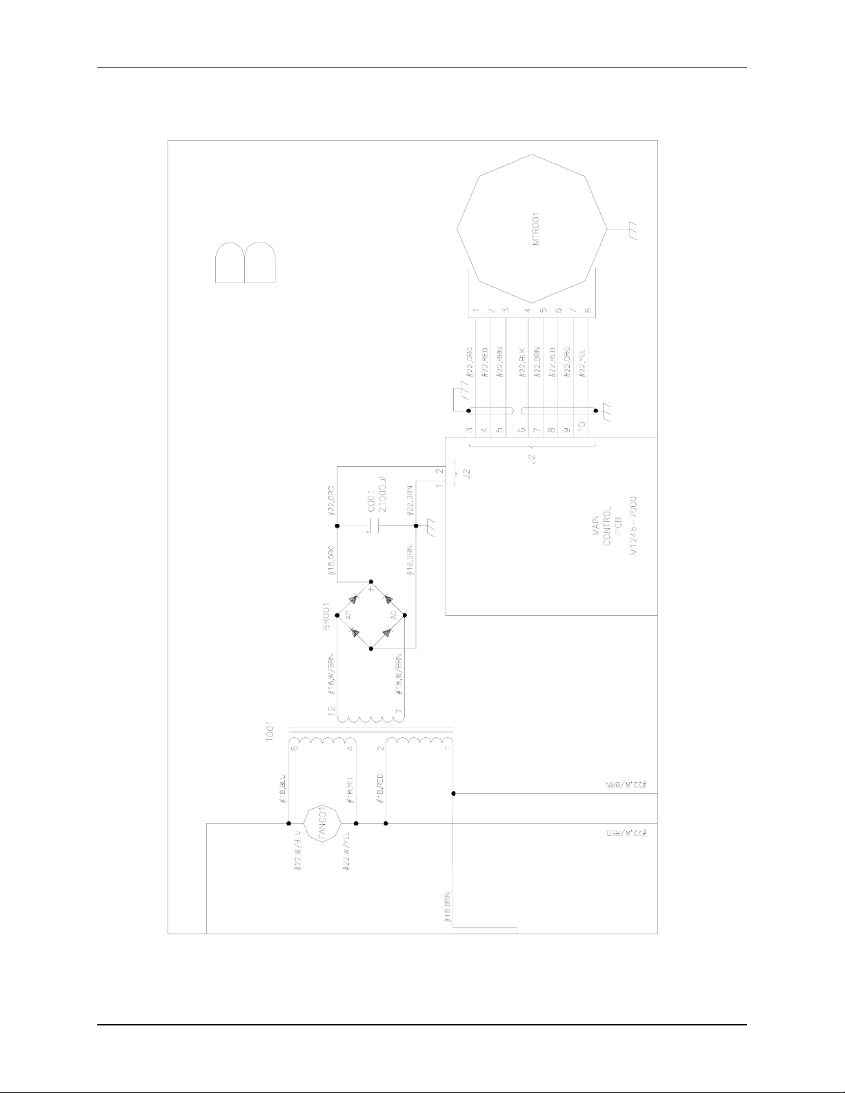
Figure 12b: C-25KC 230 VAC Control Schematic (Section B)
M1246-0051 YC-25 & C-25KC Classic Incubator Shakers User’s Guide
Artisan Technology Group - Quality Instrumentation ... Guaranteed | (888) 88-SOURCE | www.artisantg.com
Page 58
57
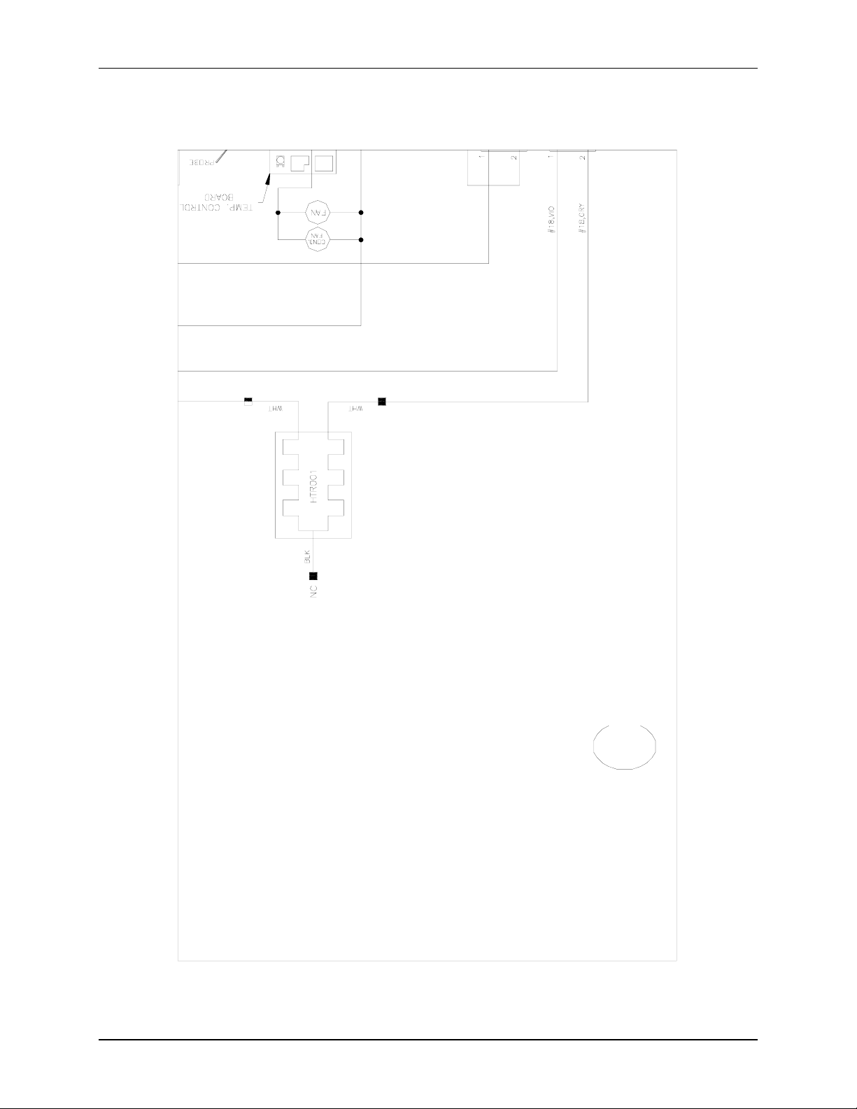
Figure 12c: C-25KC 230 VAC Control Schematic (Section C)
New Brunswick Scientific Co., Inc. User’s Guide
Artisan Technology Group - Quality Instrumentation ... Guaranteed | (888) 88-SOURCE | www.artisantg.com
Page 59
58
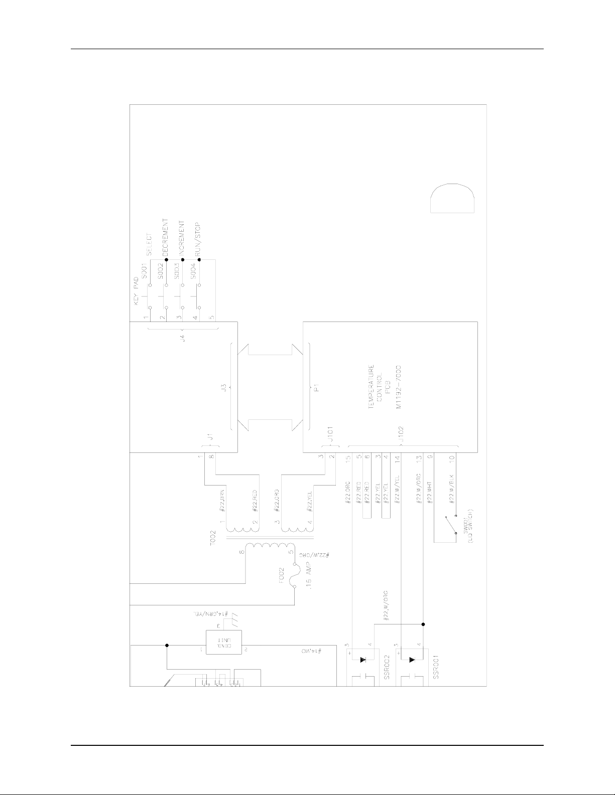
Figure 12d: C-25KC 230 VAC Control Schematic (Section D)
M1246-0051 YC-25 & C-25KC Classic Incubator Shakers User’s Guide
Artisan Technology Group - Quality Instrumentation ... Guaranteed | (888) 88-SOURCE | www.artisantg.com
Page 60
59
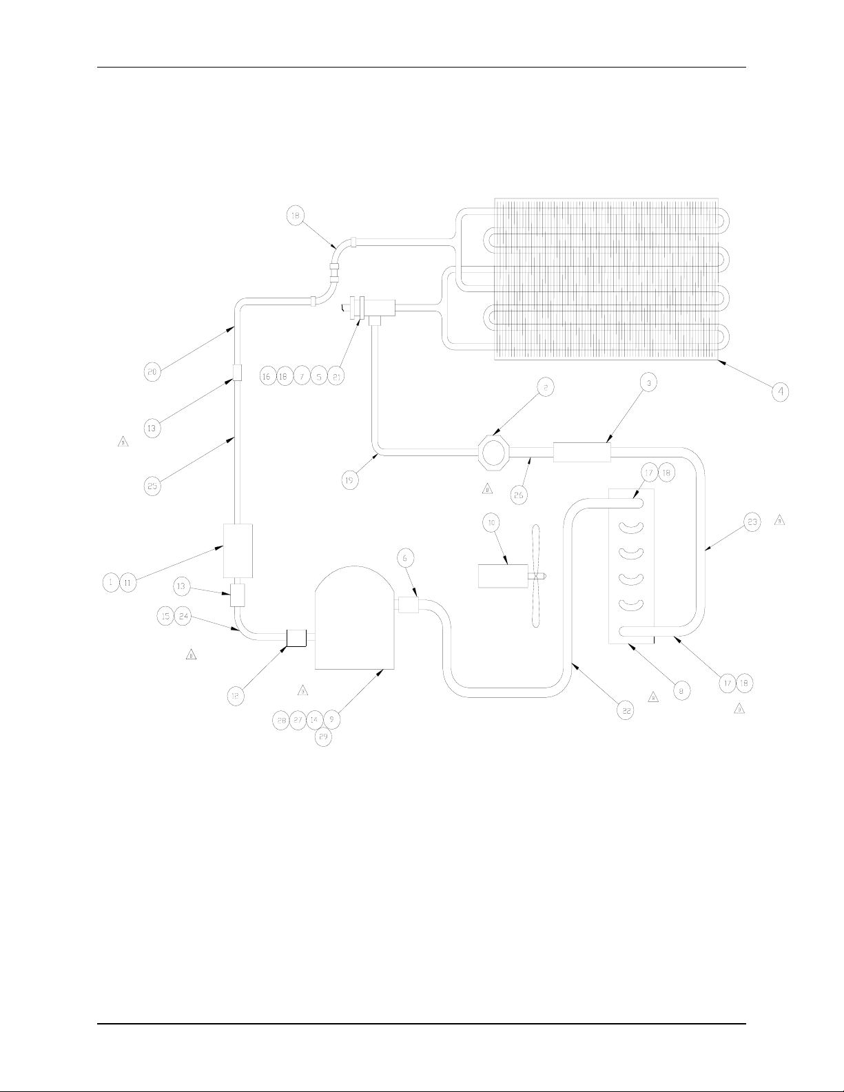
Figure 13: C-25KC Refrigeration Schematic
Callouts are identified in Table 6 on the following page.
New Brunswick Scientific Co., Inc. User’s Guide
Artisan Technology Group - Quality Instrumentation ... Guaranteed | (888) 88-SOURCE | www.artisantg.com
Page 61

60
Table 6: Callouts from Refrigeration Schematic
Item # Part Number Description Qty.
1 P0840-0120 Refrigerant R134A A/R
2 A-150 Sight Glass 1
3 P0220-1210 Filter/Dryer 1
4 M1193-9949 Cooling Coil 1
5 P0220-2081 Valve Diap. Refrigerant Brass 1
6 W-1003 Coupling Cop Rlldstop 1/4” C-C 1
7 W-2312
8 M1164-0100 Condenser Unit 1
9 P0620-0811 Compressor 115 VAC 60 Hz, 1 phase 1
10 P0620-2591
11 P0220-4600 Vlv Shut Off Refrn 1
12 W-1010 Coupling 3/8” X 5/16” Copper 1
13 W-1009 Coupling Cop Rlldstop 3/8” C-C 2
14 M1164-0640 Base Assembly 1
15 P0740-3201 Tubing, Poleyth, 3/8” ID X 3/8” WAL 3
16 W-2115
17 W-1706 Bushing Flsh 1/4” X 1/8” 2
18 W-2009
19 M1246-9112 Tube 1
20 M1246-9113 Tube 1
21 M1246-9114 Tube 1
22 M1246-9115 Tube 1
23 M1246-9116 Tube 1
24 M1246-9117 Tube 1
25 M1246-9118 Tube 1
26 M1246-9119 Tube 1
27 S1121-6089 Screw, 1/4-20 X 1/2” 4
28 W1217-3128 Washer, 1/4” Lock Zinc 4
29 M1246-9311 Adapter Base 1
Elbow, 90°, 1/4” X 1/4” CP
Fan 6” Round Alum. 100°C
Elbow, 90°, 3/8” X 1/4” Br
Elbow, 90°, 1/4” X 1/4” CP
1
1
1
4
M1246-0051 YC-25 & C-25KC Classic Incubator Shakers User’s Guide
Artisan Technology Group - Quality Instrumentation ... Guaranteed | (888) 88-SOURCE | www.artisantg.com
Page 62

61
10.1 List of Drawings
Figure Description Page
1 Keypad 21
2 Platform Screw Locations 23
3a Double Girdle Clamp Installation 24
3b Clamp Fastener 24
4 C-25 and C-25KC Rear Panel 26, 31
5 C-25 and C-25KC Front Panel 27
6 Fuse Holder (detail) 32
7 Belt Removal 33
8 Flexure Attaching Hardware (reverse view) 33
9 C-25 115 VAC Control Schematic 39
10 C-25 230 VAC Control Schematic 44
11 C-25KC 115 VAC Control Schematic 49
12 C-25KC 230 VAC Control Schematic 54
13 C25KC Refrigeration Schematic 59
10.2 List of Tables
Table Description Page
1 Clamp Hardware Application Chart 25
2 Service Parts 37
3 Platforms 37
4 Universal Platform Flask Capacity 38
5 Carriers & Test Tube Racks 38
6 Callouts from Refrigeration Schematic 60
New Brunswick Scientific Co., Inc. User’s Guide
Artisan Technology Group - Quality Instrumentation ... Guaranteed | (888) 88-SOURCE | www.artisantg.com
Page 63

62
THIS PAGE IS INTENTIONALLY BLANK
M1246-0051 YC-25 & C-25KC Classic Incubator Shakers User’s Guide
Artisan Technology Group - Quality Instrumentation ... Guaranteed | (888) 88-SOURCE | www.artisantg.com
Page 64

63
A
Accessories · 37
Alarm Functions · 29
Ambient Temperature · 13
Audible Alarm
Disabling · 29
B
Belt Replacement · 32
Belt Replacement · 33
C
Carriers · 38
CAUTION · 7
Checking Setpoints · 28
Clamp Hardware · 25
Cleaning External Surfaces · 31
Continuous Run · 28
Control Schematic
C-25KC 115VAC · 49
Control Schematics · 39
Copyright · 7
1111 I
I
Inspection · 17
Installation
Platform · 23
Installing Flask Clamps · 24
International Offices · 3
K
Keypad
Features · 21
Keypad Location · 27
L
LED Display · 21
Lid Indication · 27
Lifting the Shaker · 19
M
Maint Indicator
Disabling · 30
Manual Conventions · 7
I
NNDDEEX
X
D
Dedicated Platforms · 37
Double Girdle Clamps · 24
Drawings
Index of · 61
E
Electrical Connections · 25
Environment · 19
N
NOTE · 7
O
On/Off Switch Location · 27
Operation · 27
Overview · 13
P
F
Flask Capacity
Universal Platform · 38
Flask Clamps
Installation of · 24
Front Panel · 27
Function Indicators · 22
Fuse
Replacement · 31
Fuse Holders · 26
New Brunswick Scientific Co., Inc. User’s Guide
Platform
Installation · 23
Platform Assemblies · 22
Platforms · 37
Power Connector · 26
Power Failure · 30
Power Kit · 17
Preventive Maintenance · 31
Artisan Technology Group - Quality Instrumentation ... Guaranteed | (888) 88-SOURCE | www.artisantg.com
Page 65

64
R
Rear Panel · 26
Refrigeration Schematic
C-25KC · 59
Relative Humidity · 19
Replacement Parts · 37
S
Service Parts · 37
Setting the Timer · 28
Specifications
C-25 · 14
C-25KC · 15
Starting the Unit · 27
Status Indicators · 22
T
Table of Contents · 11
Tables
Index of · 61
Temperature Comtrol
Disabling · 29
Temperature Setpoint · 29
Test Tube Racks · 38
Timed Functions · 28
Timer
Setting the · 28
Total Running Time · 30
Troubleshooting · 35
U
Universal Platform · 37
Unlimited Run · 28
Unpacking · 17
User Interface Keys · 21
V
Visual Alarm
Disabling · 29
W
WARNING · 7
Warranty · 9
M1246-0051 YC-25 & C-25KC Classic Incubator Shakers User’s Guide
Artisan Technology Group - Quality Instrumentation ... Guaranteed | (888) 88-SOURCE | www.artisantg.com
Page 66

Artisan Technology Group is your source for quality
new and certied-used/pre-owned equipment
• FAST SHIPPING AND
DELIVERY
• TENS OF THOUSANDS OF
IN-STOCK ITEMS
• EQUIPMENT DEMOS
• HUNDREDS OF
MANUFACTURERS
SUPPORTED
• LEASING/MONTHLY
RENTALS
• ITAR CERTIFIED
SECURE ASSET SOLUTIONS
SERVICE CENTER REPAIRS
Experienced engineers and technicians on staff
at our full-service, in-house repair center
Instra
Remotely inspect equipment before purchasing with
our interactive website at www.instraview.com
Contact us: (888) 88-SOURCE | [email protected] | www.artisantg.com
SM
REMOTE INSPECTION
View
WE BUY USED EQUIPMENT
Sell your excess, underutilized, and idle used equipment
We also offer credit for buy-backs and trade-ins
www.artisantg.com/WeBuyEquipment
LOOKING FOR MORE INFORMATION?
Visit us on the web at www.artisantg.com for more
information on price quotations, drivers, technical
specications, manuals, and documentation
 Loading...