

Page 1
Document No.:VM50-9302E
Version No.: A
Vertical Machining Center
Instruction Manual
(Mechanical Part)
Page 2

Instruction manual Document No.: VM50-9302E
This manual is applicable to the following models:
VM740 series VM950 series VM1150 series VM1160 series
VM1260 series VM1360 series VM1580 series VM1780 series
VM1880 series
Page 3

Instruction manual Document No.: VM50-9302E
CONTENTS
1 Foreword .................................................................................................................... 1
2 Safety rules ................................................................................................................ 2
2.1 Symbol regulation ........................................................................................................ 2
2.2 Basics .......................................................................................................................... 2
2.3 Installation and power supply ...................................................................................... 3
2.4 Before start .................................................................................................................. 4
2.5 Preheat ........................................................................................................................ 5
2.6 Operating ..................................................................................................................... 5
2.7 Check and maintain the machine ................................................................................ 6
2.8 Matters need attention to fire ....................................................................................... 7
2.9 Safety warning sign ..................................................................................................... 8
2.10 The primary safety device. ......................................................................................... 10
2.11 Other danger ............................................................................................................. 12
3 General description ................................................................................................. 12
3.1 Machine introduction .................................................................................................. 12
3.2 Specification and parameter ......................................................................................
3.3 Environment requirement .......................................................................................... 23
4 Transportation, installation and commissioning .................................................. 23
4.1 Transportation ........................................................................................................... 23
4.2 Installation ................................................................................................................. 25
4.3 Test run and commissioning ...................................................................................... 35
5 Usage and characteristics of machine parts ......................................................... 36
5.1 Base .......................................................................................................................... 36
12
5.2 Column ...................................................................................................................... 36
5.3 Spindle head .............................................................................................................. 36
5.4 Tool magazine ........................................................................................................... 37
5.5 Air pressure pipeline .................................................................................................. 37
5.6 Cooling and chip conveyor ........................................................................................ 37
Page 1 Total 3
Page 4

Instruction manual Document No.: VM50-9302E
5.7 Table dimension drawing ........................................................................................... 37
5.8 Travel and maximum workpiece dimension ............................................................... 38
5.9 Tool shank and pull stud bolt dimension .................................................................... 39
5.10 Tool change interference diagram ............................................................................. 41
5.11 Characteristics ........................................................................................................... 42
5.12 Output characteristics of spindle motor ...................................................................... 43
5.13 Transmission system ................................................................................................. 45
5.14 Tool magazine system ............................................................................................... 46
5.15 Spindle transmission .................................................................................................. 48
5.16 Pneumatic pipeline .................................................................................................... 52
5.17 Lubricating system ..................................................................................................... 53
5.18 Cooling system .......................................................................................................... 55
5.19 CNC rotary table(optional) ......................................................................................... 56
5.20 Utilization ................................................................................................................... 56
6 Mechanical maintenance ........................................................................................ 61
6.1 Lubrication System ....................................................................................................
6.2 Hydraulic System ....................................................................................................... 62
6.3 Pneumatic system ..................................................................................................... 62
6.4 Cooling System ......................................................................................................... 62
6.5 The detail of lubrication oil and coolant ...................................................................... 63
6.6 Note ........................................................................................................................... 63
6.7 Daily inspection ......................................................................................................... 64
6.8 Weekly inspection ...................................................................................................... 64
6.9 Monthly inspection ..................................................................................................... 64
6.10 Annual inspection ...................................................................................................... 65
62
7 Common failures and troubleshooting table ........................................................ 66
7.1 Common failures and trouble shooting of feed system .............................................. 66
7.2 Common failures of tool magazine and manipulator .................................................. 67
7.3 Common failures and trouble shooting of main drive system .................................... 68
7.4 Trouble and trouble shooting of cooling system ........................................................ 68
Page 2 Total 3
Page 5

Instruction manual Document No.: VM50-9302E
7.5 Trouble and trouble shooting of pneumatic system ................................................... 69
7.6 Trouble and trouble shooting of ZF retarders ............................................................ 70
7.7 Replacement and wear parts list ............................................................................... 71
8 Recirculation and environmental protection ......................................................... 72
9 Declaration and others ............................................................................................ 72
9.1 Declaration ................................................................................................................ 72
9.2 Address and contacts ................................................................................................ 72
9.3 Illustration of machine fixation ................................................................................... 72
Page 3 Total 3
Page 6

Instruction manual Document No.: VM50-9302E
1 Foreword
The machine is for metal cutting purpose, please do not use the machine for anything
other than this purpose.
Instruction manual (mechanical part) deals with performance, safety rules, operation
and maintenance of the machine. The user must install, adjust, operate and maintain the
machine accordingly.
This instruction manual explains in detail all safety regulations and safety measures to
keep away accidents. Please read the manual first before operating the machine.
Although the instruction tries to instruct in details, while it not cover everything due to
the complexity of the machine and unpredictability of the accidents, it is impossible to predict
and describe everything possibly to happen. Only the authorized personnel with professional
operation training can work the machine.
All safety devices should be in place and should work properly.
The manufacturer is responsible for safety protection of the machine and auxiliaries
supplied to the buyer.
The buyer is responsible for the safety protection of the additional fixtures, tools and
other auxiliaries decided by themselves and for the accidents during operation for the
change of devices by themselves.
End user is responsible for not installing, operating or maintaining the machine
according to this instruction manual.
The manual is for general usage of the machine. End users have special options, may
ask for instruction manual of that specific part.
Page 1 Total 72
Page 7
Instruction manual Document No.: VM50-9302E
2 Safety rules
2.1 Symbol regulation
Indications of the warning in this manual:
Danger: If neglected, death may occur.
Warning: If neglected, either or both of operator and the machine will be damaged.
Note: If neglected, harmful results shall be brought to operator or machine.
2.2 Basics
No. Contents Remarks
1 Only can the trained and authorized personnel can operate the
machine tool.
2
Inspection, connection and maintenance shall be done by
professional to avoid electric shock.
High voltage(marked with ). Keep away from this area.
3
Never touch the terminals when checking safety of the high
voltage closure.
Danger
4
It is a must to enter the hazardous area after power cut.
5 For common metal or non-metallic materials use only. No
flammable or radioactive material is allowed.
6 Operators should wear safety glass, shoes and helmet but not
casual coats, gloves, rings, watches or other ornaments.
7
Wet hands are strictly forbidden.
8 Check the default parameters periodically. Change of default
parameters in control system is strictly forbidden. Change in
hydro system or machine parts are not allowed.
9 Never remove or change the safety covers or closures.
10 Never remove the setback switch, travel switch, stopper or
other safety device.
11 Never exceed the travel or stated capacity of the machine.
12 No more than one people is allowed to operate the control
panel.
13 To use the book correctly, operator, programmer and repairer
Warning
of this machine should read the book, the parts manuals
carefully and knows very well about the structure and theory of
mechanic, electric as well as hydro. Knows how to operate the
machine and knows about the function of the machine.
14 The operator should read the documents along with the
Page 2 Total 72
Note
Page 8
Instruction manual Document No.: VM50-9302E
machine carefully and comprehend the structure, performance,
operation and safety devices of the machine completely before
manipulating the machine.
15 Keep adequate space around the machine and keep the floor
clean.
16 The floor should be dry and clean, free from water or greasy
stains to avoid slippery.
17 Operator should know well about the location and operation of
all switches and buttons.
18 Operator must be familiar with location and operation of the
emergency switch.
19 Operator should tie up hair, fasten sleeves and coat hem.
20 When the spindle is turning and you need to do things
manually, make sure no any part of your body touches the
machine.
21 According to this instruction manual, check, adjust and
maintain the machine regularly.
22 When problems found in hydro, lubrication or cooling system,
you must cut power off to stop the machine.
23 Beware of abnormal noise, light alarm or control panel warning.
Find problem and solve at once.
24 Tools, gauges, ingots, workpieces etc. should be placed in
good order to avoid tumble or fall.
25 Never use organic solvent to clean the machine.
26 Disregarded lubricant and coolant should be treated in the way
to protect environment.
27 Check for the correctness of the program, beware of any
interference possible.
28 It is strictly forbidden to knock the tool or spindle.
29 Always adjust the belt after power off to avoid accidents.
30 After a day’s work, the machine shall be shut down in correct
sequence and cut off power.
2.3 Installation and power supply
Danger:
1) The machine must be grounded soundly ( <4 Ohm ).
2) Machines must be away from magnetic field of equipment that may cause great
voltage turbulence.
3) Machines must be away from vibration source, direct sunlight and heat producing
Page 3 Total 72
Page 9

appliances.
Warning:
1) Never carry heavy objects manually, use machines instead.
2) Enough space should be reserved in the vicinity of the machine and the floor be
clean.
3) Check programs, parameters, action sequences, tool interference, fixtures and
switches to avoid accidents or tool damages.
4) Lighting should be sufficient in the working area.
2.4 Before start
Danger:
1) Open all doors to make sure there is nobody or foreign objects inside the machine
before starting the machine.
2) Never stretch fingers between belt and pulley during belt tension check.
Warning:
1) Use recommended lubricant only.
Instruction manual Document No.: VM50-9302E
2) Check lubricant and coolant to make sure that the liquid reaches the indicator.
3) Power problem or thunder flash may cause trouble. When voltage is out of the
normal range, the power on the machine must be turned off immediately.
Note:
1) Lubricate the machine manually for the first use or the first use after idling for a
long time. Pump the lubricant to the guide way with the button on the lubricant
pump. Then start the machine with full travel.
2) Make sure the cabinet is properly shut.
3) Before working start the workshop power switch, machine power switch and start
button on the control panel one by one.
4) Prepare programs and confirm the workpiece size is within the capacity of the
machine.
5) The different temperature in different parts of the machine may influence the
accuracy of the workpiece. Preheat the machine every day for 5 to 20 minutes.
Spindle rotates at 4-5 speeds. All axes travel to full length. The above steps may
be done with a program. Check if all parts are normal during preheat. Pay more
attention when the spindle rotates at maximum speed.
6) Misoperation may damage the machine. Make sure to know the function of each
button on the control panel.
Special note: The manufacturer is not responsible for the loss caused by misoperation.
It costs to repair.
Page 4 Total 72
Page 10

2.5 Preheat
2.5.1 Aim
Before starting the machine after long time idling, the machine needs preheat to
lubricate and heated up the lubricant in order to have longer life span. Preheat the
machine every morning.
It is recommended to preheat the machine with a program instead of manual
operation.
2.5.2 How to preheat
Danger:
1) Duration:Dry run 15 minutes min. (longer in winter).
2) Spindle speed:Around 500r/min.
3) Motion:Run at feed-in and traverse speed.
4) Check with program indexing function of turret.
5) Check lubricant, hydro and coolant during preheat.
2.6 Operating
Instruction manual Document No.: VM50-9302E
Danger:
1) Stop spindle and coordinate axis when the tool magazine is changing tool. Don’t
reach the action range of ATC mechanism.
2) Stop the machine when adjusting the orientation of the cooling nozzle or the
lighting holder.
3) It is forbidden that two or more people manipulate the control panel simultaneously.
4) No glove is allowed to operate the buttons or switches to avoid misoperation.
5) Never open the closure during production.
6) Turn on the switch of the operator panel and main power supply switch when
leaving the machine tool for a while.
7) Stop the machine and eliminate the failure or notice the service people to maintain
the machine tool when abnormal phenomenon or failures occur.
Warning:
1) Never use worn out or damaged tools.
2) Make sure the connection of rivet, toolbar, auxiliary tool and cutting tool is tight and
reliable. The rivet used in the machine is standard and can’t be replaced by the one
made by the user. Otherwise, accident may occur as the accuracy or strength is
not sufficient.
3) Must run test run before working a workpiece. Check if the program is correct.
Check for the zero point, tool parameter and motion orbit. Clean the workpiece.
Make sure the workpiece is securely chucked. Make sure all adjusting tools were
removed.
Page 5 Total 72
Page 11

Instruction manual Document No.: VM50-9302E
4) Never leave tools or other objects on the control panel or other motion parts of the
machine.
Note:
1) The diameter, length and weight of the tool must be in accord with what stipulated
by the machine tool.
2) Use a brush rather than hands to clear away the chip on the tool.
3) The tool in the spindle must be changed to the tool changer before turning the
machine off. If the tool is placed in the spindle for a long time, the tool holder would
rust because of the tool’s heat-expansion and cold-contraction and corrosion of the
coolant.
4) Using lifting device when loading or unloading the workpiece with over 20kg in
weight. At least two people are needed to load and unload the large workpiece.
5) Don’t beat center, tool, spindle, etc. during operation.
6) Don’t clean the chip when machining. Use brush or cleaning liquid to clean the
machine after the spindle and coordinate axis stop.
7) Clean the machine tool, clear away the chip and wipe the protective cover glass
after finishing machining. Restore the machine in its original state, place the switch,
handle in the non-work position, cut off the power supply and carry on the
handover system earnestly.
8) Press the key with appropriate strength and don’t beat the keyboard, key and
display screen.
9) The light get hot after long work. Keep away from burning.
2.7 Check and maintain the machine
2.7.1 Don’t carry out any maintenance operation without any permission or direction.
2.7.2 Only can the trained personnel do the appointed maintenance work.
2.7.3 The maintenance of electricity should be carried out by the professional personnel who
should have a good command of machine tool program.
2.7.4 Hang “Machine tool in service” sign in the vicinity of the machine when maintaining.
2.7.5 Cut off the power supply before replacing any electrical element.
2.7.6 To guard against unexpected hazards, take down the fuse or hang “machine tool in
inspection, power supply is forbidden” sign when maintaining.
2.7.7 Use ladder or relative safety equipment when working in high place.
2.7.8 Eligible cable and lifting device should be used when using hoisting apparatus.
2.7.9 The position of travel limit block and other switch shouldn’t be changed.
2.7.10 Use the designated one when replacing the component.
2.7.11 Contact the supplier and ask for help immediately when facing the problem difficult to
diagnose and solve.
2.7.12 When performing the maintenance work, to avoid chips entering into guideways and
Page 6 Total 72
Page 12

Instruction manual Document No.: VM50-9302E
lead screw nuts, air gun can't be used.
2.8 Matters need attention to fire
2.8.1 About coolant
1) Never use oily coolant. It may be lit by hot chips or sparkles.
2) When oily coolant is the only choice, please refer to the following:
Check the tool edge and the life span and set the cutting status that will never
cause any sparkles
Clean the coolant filter periodically to ensure enough flow. Also check the flow
regularly.
In order to prevent fire, the operator has to raise vigilance and fire extinguishers
must be available near the machine.
No flammable material is allowed to stay near the machine.
Never have a large pile of chips.
Clean the machine and make sure the machine works OK.
Unmanned operation is not allowed.
Before using the oily coolant, fire protection devices like automatic fire extinguisher
has to be set. Please inform us of the intention during machine negotiations.
2.8.2 Inflammable material machining
Before the machining of any inflammable material such as magnesium and
magnesium alloy, carefully study and understand the properties of the material, follow
the instructions above and take all measures to prevent fire.
2.8.3 About dry run
The result of dry cutting without coolant may cause fire, due to the fact that there is
no coolant for the tools and the workpieces. There shall be no inflammable material
around the machine or the chips.
Check for the tool status, cutting condition, tool life span etc., and take
measurement whenever necessary.
Page 7 Total 72
Page 13
Instruction manual Document No.: VM50-9302E
2.9 Safety warning sign
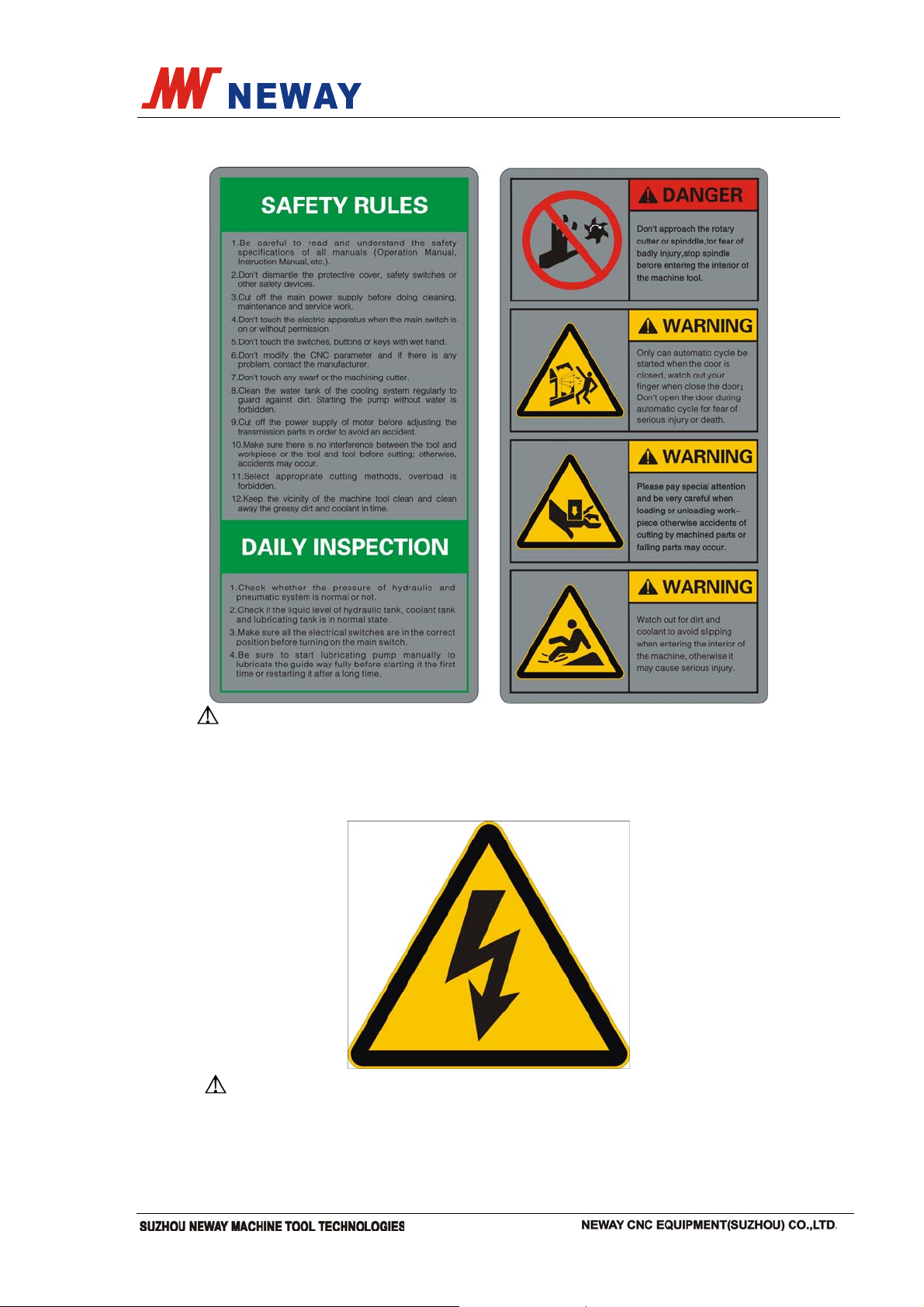
2.9.1 Integrated warning sign
Warning: The key points of the Instruction Manual are listed in the sign and the
operator should be completely familiar with the content. It also contains the details
should be noticed when the machine is running to guard against accidents.
2.9.2 Lightning warning sign
Warning: Applied where there is high voltage current and danger.
Page 8 Total 72
Page 14
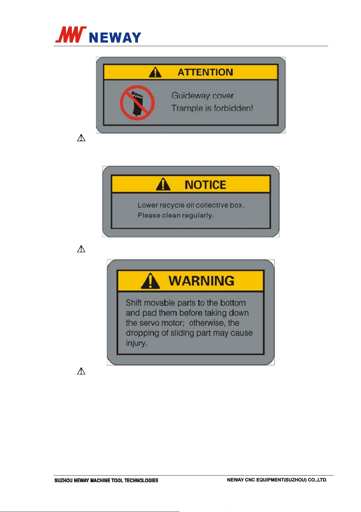
2.9.3 Other warning sign
Warning: Applied to tell operator not to step on the telescopic cover of guide way lest
damage the machine tool parts.
Instruction manual Document No.: VM50-9302E
Warning: Applied to remind operator to clean oil collective box regularly.
Warning: Applied to remind the operator what should be done when dismantling the
motor.
Page 9 Total 72
Page 15
Instruction manual Document No.: VM50-9302E
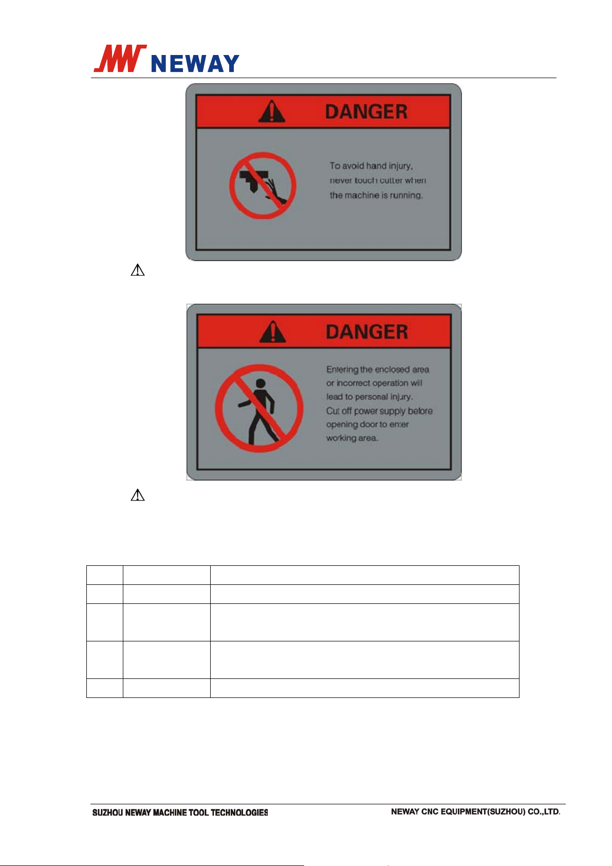
Warning: Applied to tell the operator to pay attention to safety notes and not to touch
the cutter when the machine is running to avoid injury.
Warning: Applied to tell operator to be cautious and cut off power supply before
entering the working area.
2.10 The primary safety device.
2.10.1 Safety device function and position
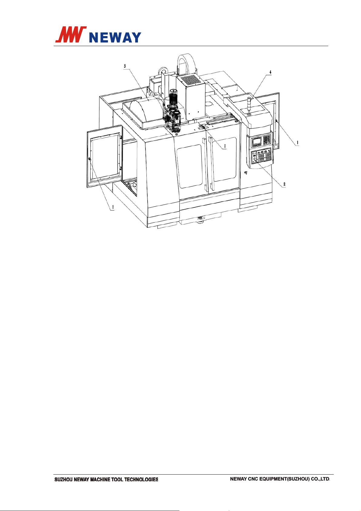
NO. Name Function
1 Door lock(3) Do not open the door during the automatic cycle.
Emergency
2
stop button(1)
Tool changer
3
guard
4
Tricolor light
1. Emergency stop button is set on the operator’s keypad.
2. The machine will stop when the button is used.
Protecting tools by preventing chips and coolant from entering
the tool changer.
Indicating machine tool’s operation status.
Page 10 Total 72
Page 16
Instruction manual Document No.: VM50-9302E
2.10.2 Matters need attention to observation window
Usually the glass on the window works for 2 years and then need to be replaced
with new glass for safety sake. But whenever the following happens, you need to
change the glass at once. There shall be accidents otherwise.
1) Convex, concave or cracks
2) Seals damage, coolant leakage
3) Glass changes color, or become frosted
4) Other damages to the glass
Notice for Cleaning:
1) Clean with soft cloth other than tools or hard cloth.
2) Clean dirt with cold or warm water, use mild detergent for difficult dirt.
3) Never use organic like thinner, ethyl or strong alkaline detergent.
4) When the surface is stained with chemicals, the stains must be removed very soon
with soft cloth and ethyl alcohol, otherwise the steel might crack or break.
2.10.3 Safe escape
The machine is able to perform many complicated motions but the motions must be
arranged by programs that are correctly, reasonably and orderly edited. The programs
must be tested carefully. Based on the characteristics and structure of the machine, we
require the following safety measurement be taken to avoid machine parts damage and
normal usage.
2.10.4 To read this manual carefully, have operation and maintenance skills, familiar with the
Page 11 Total 72
Page 17

Instruction manual Document No.: VM50-9302E
structure and characteristics of the parts beforehand and be ready to work on the
machine.
2.11 Other danger
Danger: Place a square timber between worktable and spindle box in case gravity
cause the spindle box decline which would cause accident while dismantling the Z axis
servo motor.
Warning: Equip with stable and suitable electricity for the machine. Whenever the
voltage exceeds the allowable value, you must install voltage stabilizer to ensure the
machine works normally and protect machine components from being damaged.
Note: When difficult problems found, do not solve it carelessly, contact manufacturer
immediately. Don’t dispose until the problem is clear. In short, the operator should
careful and serious during operating the machine. Try to avoid accident occur.
3 General description
3.1 Machine introduction
This machine tool is a vertical machining center with movable column. With
mechatronics design, it has a graceful outlook and can realize precision cutting. In a
single set-up, it can finish milling, drilling, boring, reaming, counterboring, tapping, etc.
automatically and continuously and is suitable for the machining of a small or medium
size valve body and rotation-type parts, etc. for small and medium-batch. The
workpieces machined by the machine is of high quality.
The machine tool has a good rigidity and high accuracy and is suitable for the
following industries: automobile component, mold, valve, mechanical engineering, IT
device, optical device, medical treatment device, etc.
If equipped with CNC rotary table (optional equipment), the machine can process
the complex workpieces with 4 or 5 axes moving simultaneously and the working range
is enlarged. The mechanical part is composed of mainframe, chip conveyor, operating
station, electrical chest, air pressure pipeline, etc. The machine tool is capable of rigid
tapping.
3.2 Specification and parameter
Note: This parameter list is standard configuration for this size. Any change of selective
configuration, please in kind prevail. Any enquiry please contact us.
Page 12 Total 72
Page 18

Table
Instruction manual Document No.: VM50-9302E
Item Unit VM740H/S VM740HL/SL
Table dimension mm 750×420 750×420
Maximum load of table kg 350 350
Left-right travel of table X/Y/Z axis mm 650/420/500 650/420/500
travel
Rapid
traverse
speed
Spindle
Tool
magazine
Distance from spindle nose to the
table surface
Distance from spindle center to the
surface of guide way of column
Rapid traverse speed of X/Y/Z axis m/min 40/40/30 48/48/48
Power of spindle motor Kw 5.5/7.5 5.5/7.5
The maximum spindle speed rpm 10000
Spindle taper hole
Tool magazine capacity T 20 20
Type of tool shank MAS403 BT40 MAS403 BT40
Maximum diameter of tool, length
and weight
mm
mm 485 485
mm/mm
/Kg
120~620 120~620
12000(Direct
drive)
7:24
NO.40
Φ80/300/8 Φ80/300/8
7:24
NO.40
Process
capacity
Precision
of
Machine
Tool change time(tool-to-tool) s 1.7 1.7
Drilling(normalizing
medium-carbon-steel)
Tapping(normalizing
medium-carbon-steel)
Milling(normalizing
medium-carbon-steel)
Positioning accuracy(X/Y/Z)
Repeat positioning accuracy(
X/Y/Z)
Automatic chip conveyor OPT. OPT.
Machine tool weight kg 4000 3500
Page 13 Total 72
mm Φ30 Φ30
mm M16 M16
3
cm
/min 150 150
mm 0.008 0.008
mm 0.005 0.005
Page 19

Instruction manual Document No.: VM50-9302E
Item Unit VM950H/S VM950HR/SR
Table
travel
Rapid
traverse
speed
Spindle
Table dimension mm
Maximum load of table kg
Left-right travel of table X/Y/Z axis mm
Distance from spindle nose to the
mm
table surface
Distance from spindle center to the
mm
surface of guide way of column
Rapid traverse speed of X/Y/Z axis m/min
Power of spindle motor Kw
The maximum spindle speed rpm
Spindle taper hole
950×520 950×520
600 600
850/520/560 850/520/560
150~710 150~710
590 590
36/36/30(H)
30/30/24(S)
7.5/11 7.5/11
8000 8000
7:24
NO.40
20/20/18
7:24
NO.40
Tool
magazine
Process
capacity
Precision
of
Machine
Tool magazine capacity T
Type of tool shank
Maximum diameter of tool, length
and weight
Tool change time(tool-to-tool) s
Drilling(normalizing
medium-carbon-steel)
Tapping(normalizing
medium-carbon-steel)
Milling(normalizing
medium-carbon-steel)
Positioning accuracy(X/Y/Z)
Repeat positioning accuracy(
X/Y/Z)
Automatic chip conveyor
mm/mm
/Kg
mm
mm
cm
mm
mm 0.005 0.005
3
/min
24 24
MAS403 BT40 MAS403 BT40
Φ78/300/8 Φ78/300/8
1.8 1.8
Φ40 Φ40
M20 M20
200 200
0.008 0.012/0.01/0.01
STD. STD.
Machine tool weight kg
Page 14 Total 72
6000 6000
Page 20

Instruction manual Document No.: VM50-9302E
Item Unit VM950HL/SL VM950V
Table
travel
Rapid
traverse
speed
Spindle
Table dimension mm
Maximum load of table kg
Left-right travel of table X/Y/Z axis mm
Distance from spindle nose to the
mm
table surface
Distance from spindle center to the
mm
surface of guide way of column
Rapid traverse speed of X/Y/Z axis m/min
Power of spindle motor Kw
The maximum spindle speed rpm
Spindle taper hole
950×520 950×520
500 500
850/520/560 850/520/560
120~680 120~680
575 575
40/40/30 40/40/30
7.5/11 15/17.9
12000(Direct
drive)
7:24
NO.40
15000
7:24
NO.40
Tool
magazine
Process
capacity
Precision
of
Machine
Tool magazine capacity T
Type of tool shank
Maximum diameter of tool, length
and weight
Tool change time(tool-to-tool) s
Drilling(normalizing
medium-carbon-steel)
Tapping(normalizing
medium-carbon-steel)
Milling(normalizing
medium-carbon-steel)
Positioning accuracy(X/Y/Z)
Repeat positioning accuracy(
X/Y/Z)
mm/mm
/Kg
mm
mm
3
cm
mm
mm 0.005 0.005
/min
24 24
MAS403 BT40 BBT40
Φ78/300/8 Φ78/300/8
1.8 1.8
Φ40 Φ20
M20 M12
200 80
0.008 0.008
Automatic chip conveyor
Machine tool weight kg 5000
Page 15 Total 72
OPT. OPT.
5000
Page 21

Instruction manual Document No.: VM50-9302E
Table
travel
Rapid
traverse
speed
Spindle
Item Unit VM1150H/S
Table dimension mm
Maximum load of table kg
Left-right travel of table X/Y/Z axis mm
Distance from spindle nose to the
mm
table surface
Distance from spindle center to the
mm
surface of guide way of column
Rapid traverse speed of X/Y/Z axis m/min
Power of spindle motor Kw
The maximum spindle speed rpm
Spindle taper hole
VM1150HR/SR
1100×520 1100×520
750 750
1000/520/560 1000/520/560
150~710 150~710
590 590
36/36/30(H)
30/30/24(S)
7.5/11 7.5/11
8000 8000
7:24
NO.40
20/20/18
7:24
NO.40
Tool
magazine
Process
capacity
Precision
of
Machine
Tool magazine capacity T
Type of tool shank
Maximum diameter of tool, length
and weight
Tool change time(tool-to-tool) s
Drilling(normalizing
medium-carbon-steel)
Tapping(normalizing
medium-carbon-steel)
Milling(normalizing
medium-carbon-steel)
Positioning accuracy(X/Y/Z)
Repeat positioning accuracy(
X/Y/Z)
Automatic chip conveyor
mm/mm
/Kg
mm
mm
cm
mm
mm 0.005
3
/min
24 24
MAS403 BT40 MAS403 BT40
Φ78/300/8 Φ78/300/8
1.8 1.8
Φ40 Φ40
M20 M20
200 200
0.008 0.02/0.01/0.01
0.01/0.008/0.00
8
STD. STD.
Machine tool weight kg
Page 16 Total 72
7000 7000
Page 22

Instruction manual Document No.: VM50-9302E
Item Unit VM1150HL/SL VM1150V
Table
travel
Rapid
traverse
speed
Spindle
Table dimension mm
Maximum load of table kg
Left-right travel of table X/Y/Z axis mm
Distance from spindle nose to the
mm
table surface
Distance from spindle center to the
mm
surface of guide way of column
Rapid traverse speed of X/Y/Z axis m/min
Power of spindle motor Kw
The maximum spindle speed rpm
Spindle taper hole
1100×520 1100×520
600 600
1000/520/560 1000/520/560
120~680 120~680
575 575
40/40/30 40/40/30
7.5/11 15/17.9
12000(Direct
drive)
7:24
NO.40
15000
7:24
NO.40
Tool
magazine
Process
capacity
Precision
of
Machine
Tool magazine capacity T
Type of tool shank
Maximum diameter of tool, length
and weight
Tool change time(tool-to-tool) s
Drilling(normalizing
medium-carbon-steel)
Tapping(normalizing
medium-carbon-steel)
Milling(normalizing
medium-carbon-steel)
Positioning accuracy(X/Y/Z)
Repeat positioning accuracy(
X/Y/Z)
mm/mm
/Kg
mm
mm
3
cm
mm
mm 0.005 0.005
/min
24 24
MAS403 BT40 BBT40
Φ78/300/8 Φ78/300/8
1.8 1.8
Φ40 Φ20
M20 M12
200 80
0.008 0.008
Automatic chip conveyor OPT.
Machine tool weight kg 6000
Page 17 Total 72
OPT.
6000
Page 23

Instruction manual Document No.: VM50-9302E
Table
travel
Rapid
traverse
speed
Spindle
Item Unit VM1160H/S
Table dimension mm
Maximum load of table kg
Left-right travel of table X/Y/Z axis mm
Distance from spindle nose to the
mm
table surface
Distance from spindle center to the
mm
surface of guide way of column
Rapid traverse speed of X/Y/Z axis m/min
Power of spindle motor Kw
The maximum spindle speed rpm
Spindle taper hole
VM1260H/S
1100×600 1200×600
750 800
1000/600/560 1050/600/600
150~710 140~740
659 649
36/36/30(H)
30/30/24(S)
7.5/11 11/15
8000 8000
7:24
NO.40
30/30/24
7:24
NO.40
Tool
magazine
Process
capacity
Precision
of
Machine
Tool magazine capacity T
Type of tool shank
Maximum diameter of tool, length
and weight
Tool change time(tool-to-tool) s
Drilling(normalizing
medium-carbon-steel)
Tapping(normalizing
medium-carbon-steel)
Milling(normalizing
medium-carbon-steel)
Positioning accuracy(X/Y/Z)
Repeat positioning accuracy(
X/Y/Z)
Automatic chip conveyor
mm/mm
/Kg
mm
mm
cm
mm
mm 0.005 0.005
3
/min
24 24
MAS403 BT40 MAS403 BT40
Φ78/300/8 Φ78/300/8
1.8 1.8
Φ40 Φ45
M20 M24
200 250
0.008 0.008
STD. STD.
Machine tool weight kg
Page 18 Total 72
7200 7500
Page 24

Instruction manual Document No.: VM50-9302E
Table
travel
Rapid
traverse
speed
Spindle
Item Unit
Table dimension mm
Maximum load of table kg
Left-right travel of table X/Y/Z axis mm
Distance from spindle nose to the
mm
table surface
Distance from spindle center to the
mm
surface of guide way of column
Rapid traverse speed of X/Y/Z axis m/min
Power of spindle motor Kw
The maximum spindle speed rpm
Spindle taper hole
VM1260HR/SR
/RZ(Gear Drive)
1250×600 1350×600
1000 1000
1050/600/600 1200/600/600
150~750(HR)
120~720(RZ)
665 665
20/20/18
11/15 11/15
8000/6000 8000
7:24
NO.40(HR)
NO.50(RZ)
VM1360H/S
150~750
36/36/24(H)
24/24/20(S)
7:24
NO.40
Tool
magazine
Process
capacity
Precision
of
Machine
Tool magazine capacity T
Type of tool shank
Maximum diameter of tool, length
and weight
Tool change time(tool-to-tool) s
Drilling(normalizing
medium-carbon-steel)
Tapping(normalizing
medium-carbon-steel)
Milling(normalizing
medium-carbon-steel)
Positioning accuracy(X/Y/Z)
Repeat positioning accuracy(
X/Y/Z)
mm/mm
/Kg
mm
mm
3
cm
mm
mm 0.008 0.005
/min
24 24
MAS403BT40
BT50(RZ)
Φ80/300/8
Φ110/350/15
(RZ)
1.8 1.8
Φ45/Φ65 Φ45
M24/M40 M24
250/360 250
0.012/0.01/0.01 0.008
MAS403 BT40
Φ80/300/8
Automatic chip conveyor
Machine tool weight kg
Page 19 Total 72
STD. STD.
8000 9000
Page 25

Instruction manual Document No.: VM50-9302E
Table
travel
Rapid
traverse
speed
Spindle
Item Unit
Table dimension mm 1350×600
Maximum load of table kg 1000
Left-right travel of table X/Y/Z axis mm 1200/600/600
Distance from spindle nose to the
mm
table surface
Distance from spindle center to the
mm 665
surface of guide way of column
Rapid traverse speed of X/Y/Z axis m/min 20/20/18
Power of spindle motor Kw 11/15
The maximum spindle speed rpm 8000/6000
Spindle taper hole
Tool magazine capacity T 24
VM1360HR
/RZ(Gear Drive)
150~750
7:24
NO.40(HR)
NO.50(RZ)
VM1580H/S
1500×800
1250
1350/800/680
150~830
868
30/30/24(H)
24/24/20(S)
15/18.5
6000
7:24
NO.50
24
Tool
magazine
Process
capacity
Precision
of
Machine
Type of tool shank
Maximum diameter of tool, length
and weight
Tool change time(tool-to-tool) s 1.8
Drilling(normalizing
medium-carbon-steel)
Tapping(normalizing
medium-carbon-steel)
Milling(normalizing
medium-carbon-steel)
Positioning accuracy(X/Y/Z)
Repeat positioning accuracy(
X/Y/Z)
mm/mm
/Kg
mm Φ45/Φ65
mm M24/M40
3
cm
/min 250/360
mm 0.012/0.01/0.01
mm 0.008
MAS403 BT40
MAS403 BT50
BT50(RZ)
Φ80/300/8
Φ110/350/15
(RZ)
0.012/0.01/0.01
0.008/0.006/0.0
Φ110/350/15
2
Φ50
M30
300
06
Automatic chip conveyor STD.
Machine tool weight kg 9000
Page 20 Total 72
STD.
11000
Page 26

Instruction manual Document No.: VM50-9302E
Table
travel
Rapid
traverse
speed
Spindle
Item Unit
Table dimension mm 1500×800
Maximum load of table kg 1250
Left-right travel of table X/Y/Z axis mm 1350/800/680
Distance from spindle nose to the
mm
table surface
Distance from spindle center to the
mm
surface of guide way of column
Rapid traverse speed of X/Y/Z axis m/min 18/18/15
Power of spindle motor Kw 15/18.5
The maximum spindle speed rpm 6000/6000
Spindle taper hole
VM1580HR
/RZ(Gear Drive)
150~830
868(HR)
880(RZ)
7:24
NO.50
VM1780H/S
1700×800
1500
1500/800/680
150~830
868
30/30/24(H)
24/24/20(S)
15/18.5
6000
7:24
NO.50
Tool
magazine
Process
capacity
Precision
of
Machine
Tool magazine capacity T 24
Type of tool shank
Maximum diameter of tool, length
and weight
Tool change time(tool-to-tool) s 2
Drilling(normalizing
medium-carbon-steel)
Tapping(normalizing
medium-carbon-steel)
Milling(normalizing
medium-carbon-steel)
Positioning accuracy(X/Y/Z)
Repeat positioning accuracy(
X/Y/Z)
mm/mm
/Kg
mm Φ50/Φ80
mm M30/M50
3
cm
/min 300/420
mm
mm 0.01
MAS403 BT50
Φ110/350/15
0.015/0.012/0.01
24
MAS403 BT50
Φ110/350/15
2
Φ50
M30
300
0.012/0.01/0.01
0.008/0.006/0.0
06
Automatic chip conveyor STD.
Machine tool weight kg 11000
Page 21 Total 72
STD.
13000
Page 27

Instruction manual Document No.: VM50-9302E
Table
travel
Rapid
traverse
speed
Spindle
Item Unit
Table dimension mm
Maximum load of table kg
Left-right travel of table X/Y/Z axis mm
Distance from spindle nose to the
mm
table surface
Distance from spindle center to the
mm
surface of guide way of column
Rapid traverse speed of X/Y/Z axis m/min
Power of spindle motor Kw
The maximum spindle speed rpm
Spindle taper hole
VM1780HR/RZ(
Gear Drive)
1700×800 1800×800
1500 1750
1500/800/680 1700/850/700
150~830 140~840
868(HR)
880(RZ)
18/18/15 24/24/20
15/18.5 15/18.5
6000/6000 6000
7:24
NO.50
VM1880H/S
900
7:24
NO.50
Tool
magazine
Process
capacity
Precision
of
Machine
Tool magazine capacity T
Type of tool shank
Maximum diameter of tool, length
and weight
Tool change time(tool-to-tool) s
Drilling(normalizing
medium-carbon-steel)
Tapping(normalizing
medium-carbon-steel)
Milling(normalizing
medium-carbon-steel)
Positioning accuracy(X/Y/Z)
Repeat positioning accuracy(
X/Y/Z)
mm/mm
/Kg
mm
mm
3
cm
mm
mm 0.01
/min
24 24
MAS403 BT50 MAS403 BT50
Φ110/350/15 Φ110/350/15
2 2
Φ50/Φ80 Φ50
M30/M50 M30
300/420 300
0.015/0.012/0.01
0.012/0.01/0.01
2
0.008/0.006/0.0
06
Automatic chip conveyor
Machine tool weight kg
Page 22 Total 72
STD. STD.
13000 15000
Page 28

Instruction manual Document No.: VM50-9302E
3.3 Environment requirement
3.3.1 Keeping at a constant temperature is essential for precise process.
Ambient temperature needed is 10℃~40℃,when temp is 20℃,humidity should be
40~75%.
To keep the accuracy of the machine, it is required the temp to be 15℃~25℃, the
max temp variation is ±2℃/24h.
3.3.2 Voltage:3 phase, 380V, ±10%, frequency: 50Hz,
3.3.3 Use stabilizer in the area that the voltage is not stable.
3.3.4 Machine shall be properly grounded, use copper wire with diameter no less than 10mm
resistance 4 Ohm max.
3.3.5 To let the machine performs its best, the compressed air must meet the requirement.
There shall be a purifier before the the air goes into the machine (de-water, de-grease,
filtering).
3.3.6 Keep the machine from direct sun shine, vibration or heat resource, high frequency
motor or welder, to keep the accuracy and avoid machine trouble.
2
,
4 Transportation, installation and commissioning
4.1 Transportation
4.1.1 Precautions
1) Disassemble the components like servo motor and chain of Z axis which are over
the limiting dimension before transporting and assemble the machine tool after
arrival.
2) Main body, foot board and water tank are packed and transported separately.
Should not suffer strong impact or vibration, and prohibit box upside down or
sideways.
3) Put the spindle box in the lowest position, column and saddle in the middle position,
fix with transporting mounting.
4) The pull door remains open and fixed with connecting plate. Install the shield on
operation box and fix the box. Drain out liquid from all tanks.
5) Make sure the rigging hardware and other lifting devices are strong enough.
6) When hoisting, installing the lifting bolt on the base.
7) Never let the steel wire to get in touch with soft part of the machine. Make proper
pad between steel wire rope and machine to avoid damage to the paint of the
machine.
8) Do not allow steel wire fasten on hydro pipe, air pipe, cable, electric cabinet or
hydro components.
9) Lifting pallet after removing boxes, follow the marks (lifting point, lifting direction,
gravity, upwards etc.) on the box too. The hook height must be 5 meters min.
Page 23 Total 72
Page 29
Instruction manual Document No.: VM50-9302E
above the pallet.
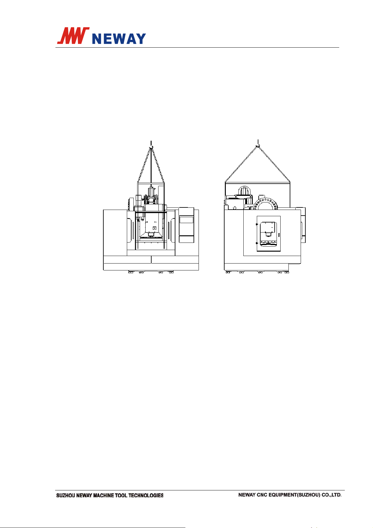
4.1.2 When hoisting the machine, installing lifting bolt on the base. Use the wirerope sling the
machine through the four point location and require the wirerope has enough strength
to load the machine. The crane and the overhead travelling crane have enough strength,
too. Remove the coolant tank before lifting. To avoid the crash of guarding cover,
electrical chest and the machine tool, stretch the upper end of the cable and put soft
wood or other soft materials in the contacting area of machine tool and cable to protect
the lacquer surface. For the lifting drawing.
Support and tighten the moving parts before lifting and transporting the machine
tool. When the machine is placed in the installing place, take away the supports and
fasteners.
The sequence of taking away the supports and fasteners:
1) Move up the spindle head and then take away the supports and fasteners of the
spindle.
2) Take down the connecting plate of carriage and base.
3) Take down the connecting plate of carriage and column.
4) Take down the connecting plate of pull door.
5) Take down the connecting plate and the shield of the operation panel.
After taking apart the fasteners, clear away the rust preventive oil on the external
machining surface, e.g. guide way, spindle taper hole, etc.
Fill the lubricating pump, hydraulic oil tank, coolant tank with designated hydraulic
oil or coolant before starting the machine. Air pipe should be installed in the air source
inlet in rear of the column. The air pressure supplied is 0.6~0.8 MPa.
Page 24 Total 72
Page 30
Instruction manual Document No.: VM50-9302E
4.2 Installation
4.2.1 The common require of device
The working environment has a direct impact on the performance and service life
of the machine. High temperature will reduce the service life of the electric component,
high humidity will cause the malfunction of CNC system and low temperature will
increase the oil viscosity and deteriorate the working condition of the pump. In addition,
it’s necessary to protect the CNC system against the electromagnetic pulse generated
from wire-electrode cutting, electric welding, etc. So the machine tool should be
installed in the workshop with good condition where the temperature, humidity, vibration,
dust, etc. are under control. To facilitate the maintenance and inspection, reserve the
appropriate space for the machine tool.
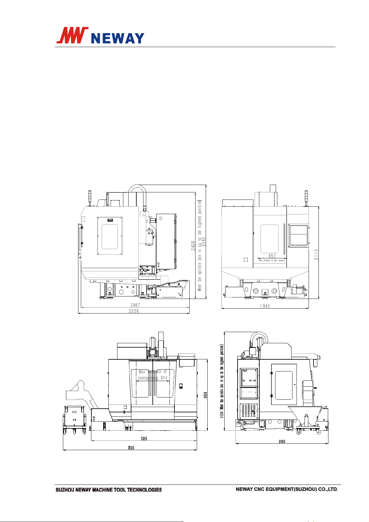
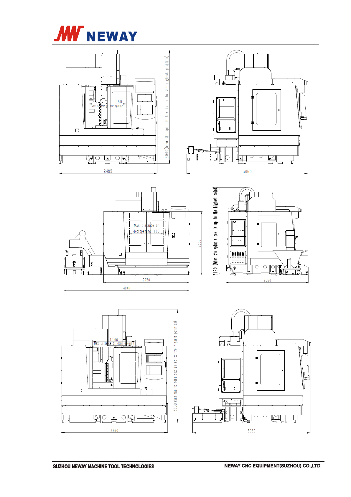
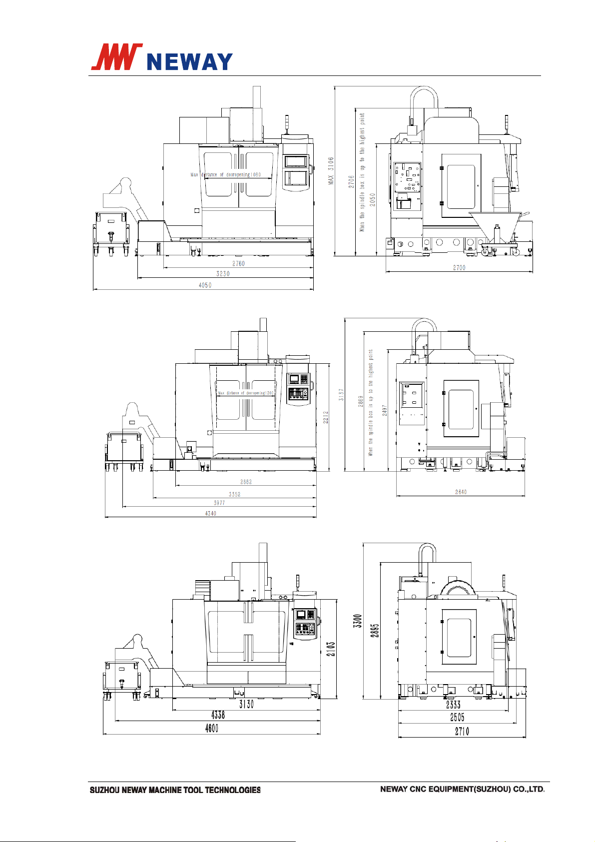
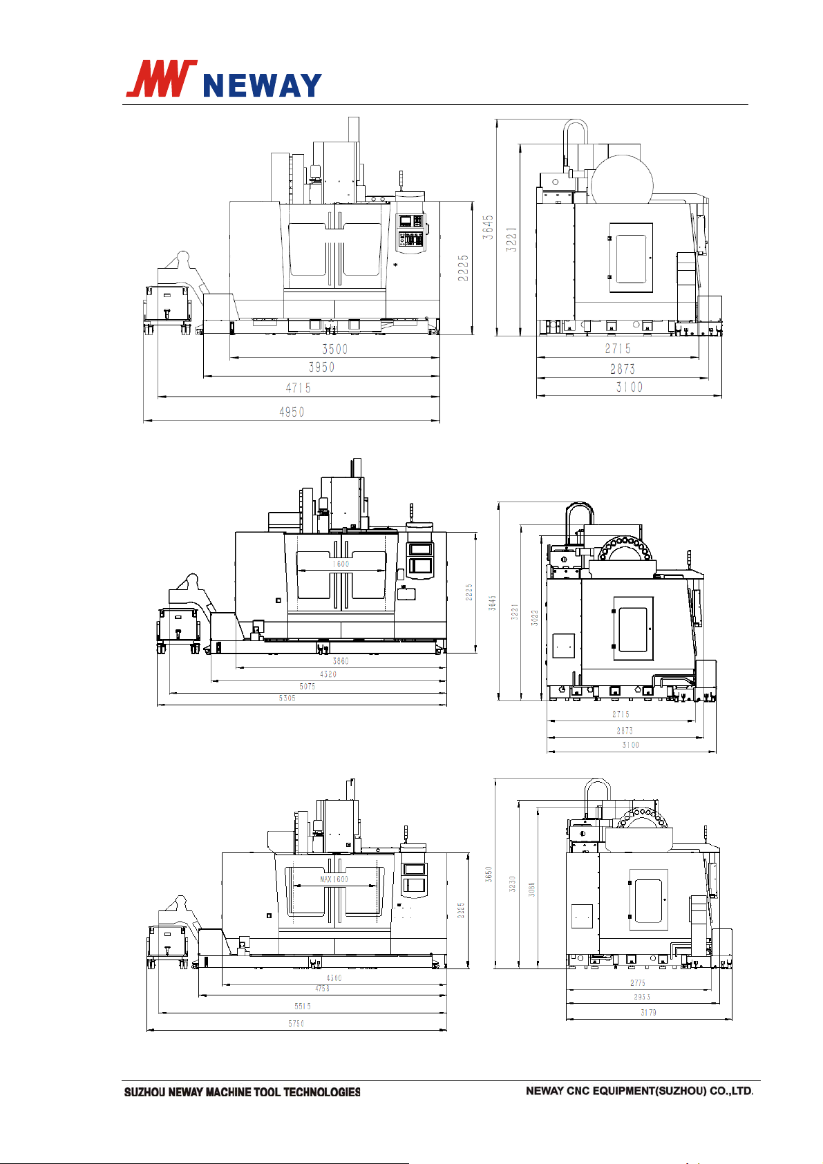
4.2.2 Outline drawing of the machine tool
(VM740)
(VM950 series except VM950HL/SL model)
Page 25 Total 72
Page 31
Instruction manual Document No.: VM50-9302E
(VM950HL/SL)
(VM1150 series except VM1150HL/SL model)
(VM1150HL/SL)
Page 26 Total 72
Page 32
Instruction manual Document No.: VM50-9302E
(VM1160)
(VM1260)
(VM1360)
Page 27 Total 72
Page 33
Instruction manual Document No.: VM50-9302E
(VM1580)
(VM1780)
(VM1880)
Page 28 Total 72
Page 34
Instruction manual Document No.: VM50-9302E
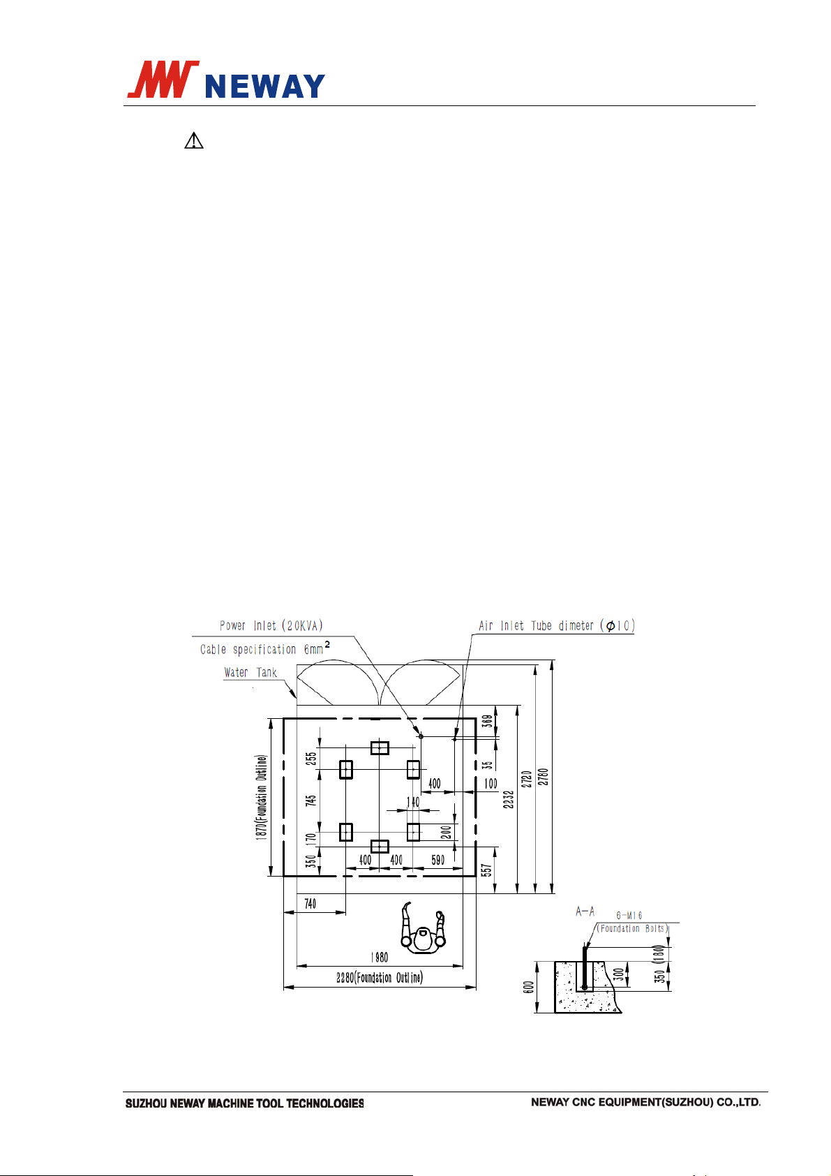
4.2.3 Basic description and foundation drawing
Note:
1) The deeper the concrete foundation, the better the stability of the machine tool.
Notice that there should not be chap in the concrete foundation.
2) Pre-measure and reserve the position of foundation bolt hole and adjusting hole.
The hole reserved had better be wedge-type and coarse to ensure the optimum
strength after grouted.
3) When grouting the concrete, reserve the earth hole and embed a copper bar of 2m
long and 15mm in diameter.
4) Install the machine 7-10 days after grouting the foundation. (The days are decided
by the specific conditions of the installing place).
5) Place the foundation bolt in the reserved hole after leveling the machine tool and
then grout the instant-dry cement.
6) For back-grouting: High-strength non-shrink grouting material.
7) The cable for power input: YJV 4*16.
8) For compressed air input: Air source filtering accuracy 100μm; outer diameter of air
pipe 10mm.
9) Lifting sling: Wire rope
10) Fine level the machine tool 7 days after the grouting.
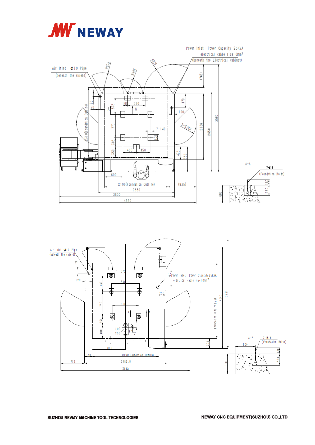
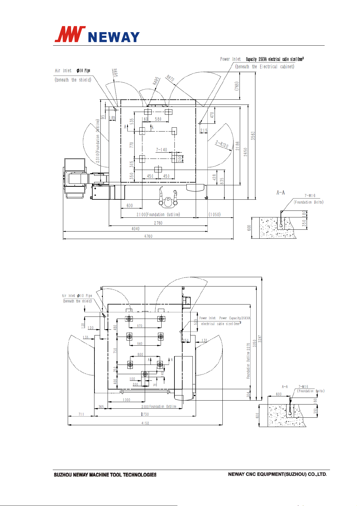
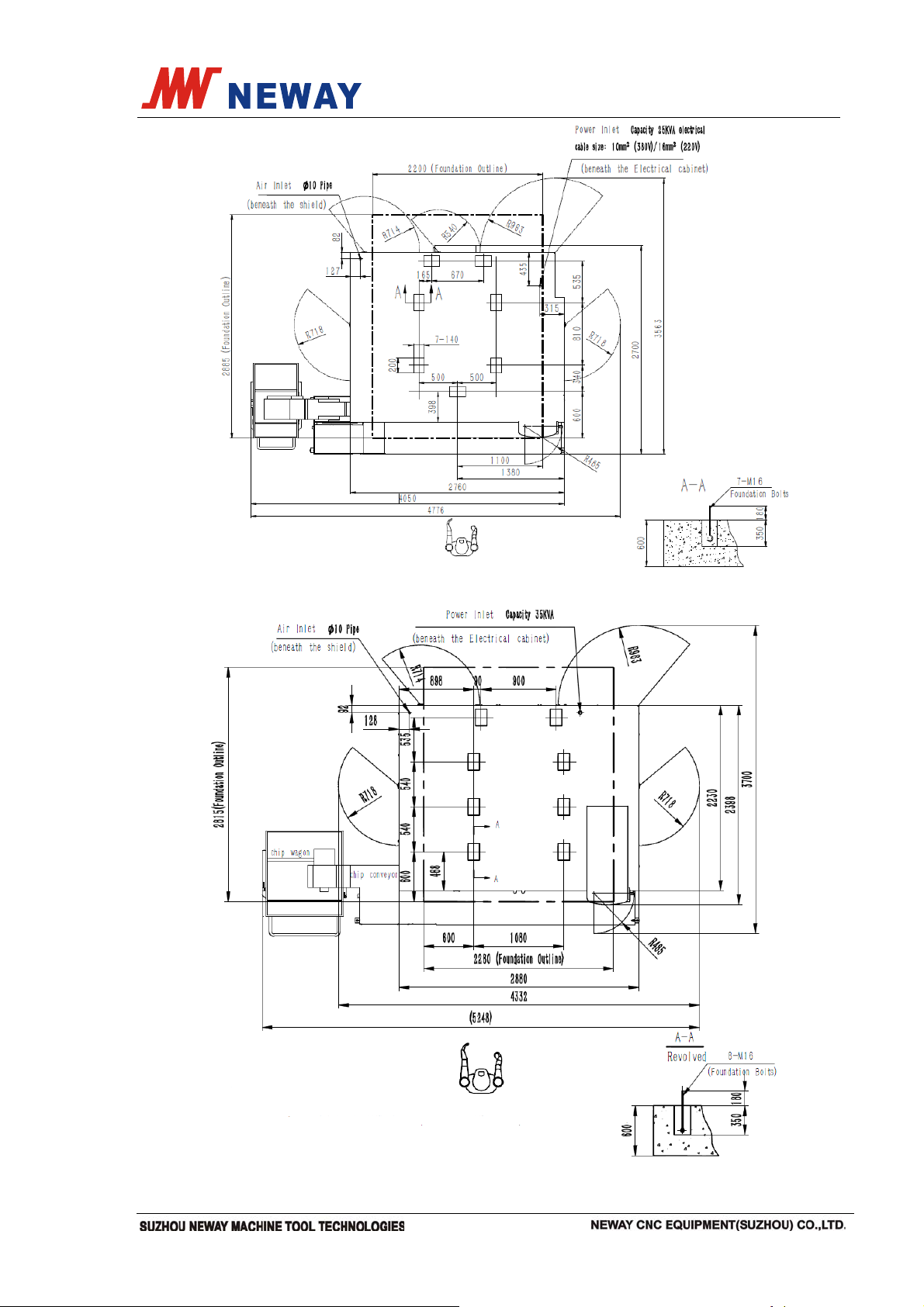
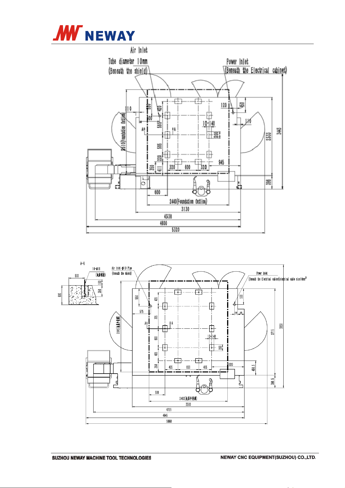
11) For the foundation drawing, see the following picture.
(VM740)
Page 29 Total 72
Page 35
Instruction manual Document No.: VM50-9302E
(VM950 series except VM950HL/SL model)
(VM950HL/SL)
Page 30 Total 72
Page 36
Instruction manual Document No.: VM50-9302E
(VM1150 series except VM1150HL/SL model)
(VM1150HL/SL)
Page 31 Total 72
Page 37
..
Instruction manual Document No.: VM50-9302E
(VM1160)
(VM1260)
Page 32 Total 72
Page 38
Instruction manual Document No.: VM50-9302E
(VM1360)
(VM1580)
Page 33 Total 72
Page 39
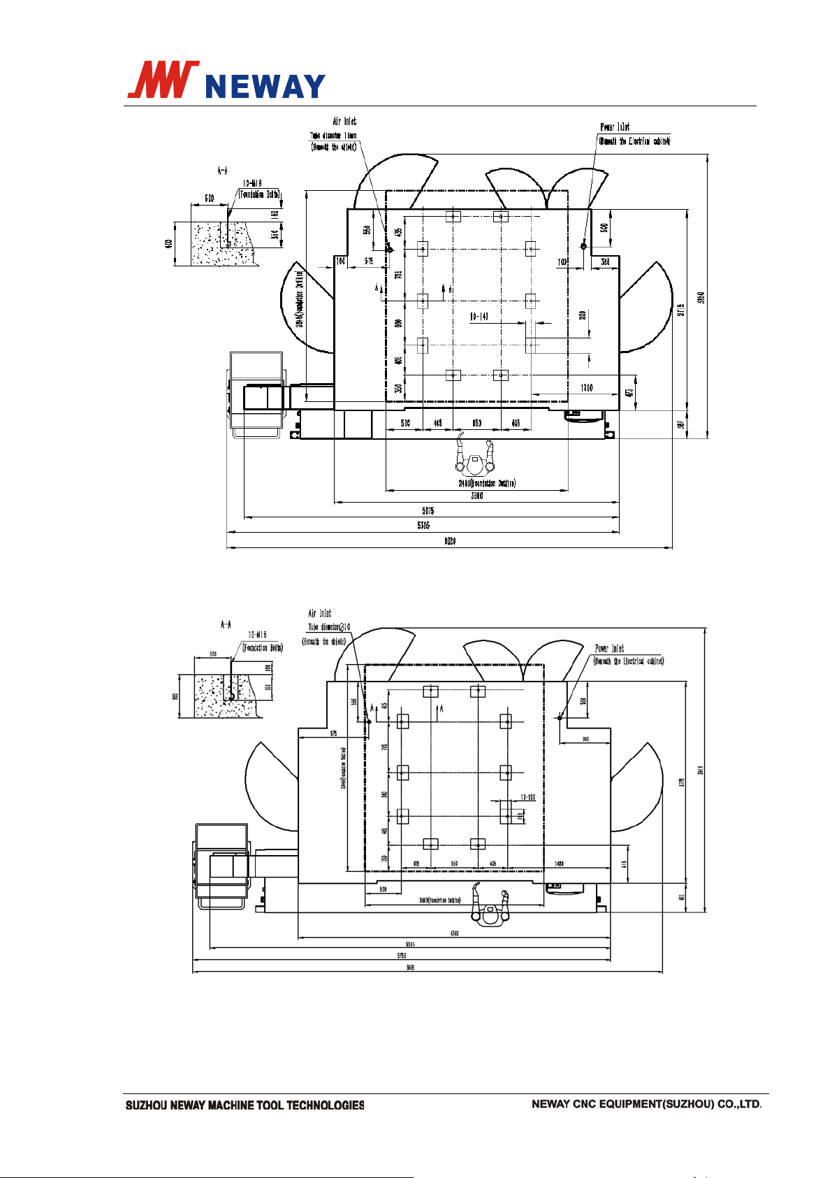
Instruction manual Document No.: VM50-9302E
(VM1780)
(VM1880)
Page 34 Total 72
Page 40

Instruction manual Document No.: VM50-9302E
4.2.4 Installation
Note:
1) Place the sizing block before laying down the machine. Make sure the sizing block
support the machine tool evenly.
2) Clear away the anti-rust oil with clean cotton clothes and then coat the machine
tool with lubricating oil.
3) Confirm the specification of voltage, frequency and phase and ground before
turning on the machine tool.
4) Connect the air pipe and adjust the air pressure to 0.6~0.8 MPa.
5) Connect the chip conveyor, cooling pump and hydraulic station and confirm the
rotary direction.
4.3 Test run and commissioning
4.3.1 To ensure the accuracy, level the machine by following the steps:
Note:
1) Place the gradienter on the center of the table.
2) Adjust the adjusting bolts in the four corners, move X-axis and Y-axis repeated until
the machine tool is level.
3) Adjust other bolts and make the weight of the machine tool distributed evenly in
each bolt without affecting the level of the machine tool.
4) The level range is 0.02~0.03mm/m.
5) In order to maintain the accuracy of the machine, check and level it at half-yearly
intervals.
4.3.2 Inspection before test run
1) Check if the saddle, column and the transportation fixed element of spindle head
are removed.
2) Check if all the components are completed, if the location and installation method
are correct.
3) Fill into the lubricant pump, cam box and grease cup with defined type and quantity
lubricating oil.
4) Fill into the hydraulic pressure station and oil cooler tank with defined type and
quantity hydraulic oil.
5) Check if all the pipes and joints connected well.
4.3.3 Before power on
1) Power capacity
There shall be good power supply for the machine, if the power is not good enough,
with insufficient capacity or great changes in voltage, there might be expectable
accidents. Please note the total capacity, what can refer to “Schematic Circuit Diagram
and Interconnection Circuit”.
Page 35 Total 72
Page 41

2) Check power phase sequence
The power phase sequence must be the same with that of this machine. Otherwise
there shall be no response from the machine. It may melt the fuse, or cause accident.
The power phase inspection is a must.
3) Check servo and spindle transformer
Connect the output end of the transformer with local power with correct connection.
Wrong connection will burn the electric parts. The connections may be different with
default according to your real situation. Refer to operation manual ( electric part).
4.3.4 Test run
Operator reads the instruction manual (mechanical, electrical or hydraulic) and
CNC control system carefully, start the machine manually then automatically following
the correct way and procedure.
4.3.5 Adjustment of machine
The velocity and strength of every hydraulic transmission of machine tool have
been adjustment to the proper status. If user needs a further adjustment, please read
the Hydraulic Operating Instruction of this machine tool.
Instruction manual Document No.: VM50-9302E
4.3.6 Operation
All code, instruction input, program edit, amendment and additional functions are
situated on the control panel. For operate the machine on the control panel, refer to the
CONTENTS of instruction manual (electric part).
5 Usage and charact eristics of machine parts
5.1 Base
With high rigidity design and manufacture, base, which is to endure the weight of
the machine tool, cutting force and cutting vibration, is the basic part of the machine tool.
There are adjusting bolts to adjust the level of the machine tool.
The table is installed on the carriage that installed above the guide way on the
base. The table is convenient for loading and unloading the workpiece. The table
moves in front-rear direction (Y direction) along with the carriage on the base and in
left-right direction (X direction) on the carriage.
5.2 Column
Column is of high rigidity and installed on the base. Tool magazine is installed on
the left side of the column, electrical chest on the right and Z-axis feed motor on the
upper.
5.3 Spindle head
Spindle head is installed on the guide way in the front of the column and moves in
up-down direction (Z direction) on the column. Spindle motor, spindle and air pressure
cylinder for tool pushing are installed in the spindle head. The power is transmitted from
motor to spindle by a toothed belt.
Page 36 Total 72
Page 42
Instruction manual Document No.: VM50-9302E
5.4 Tool magazine
Tool magazine is installed on the tool magazine support, which is fixed on the left
side of the column. Tool magazine can realize the storage and change of tool. Tool
change is quick, exact and reliable
5.5 Air pressure pipeline
The air pressure pipeline controls the action such as tool releasing of spindle,
toolbar cleaning, tool pocket moving, etc.
5.6 Cooling and chip conveyor
Chip conveyor is used for removing the chip generated in the machining process.
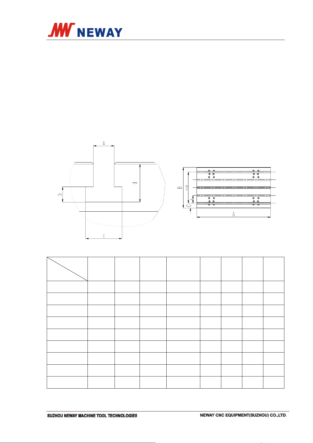
5.7 Table dimension drawing
Parameter
A B C
Type
VM740 750mm 420mm 85mm
VM950 950mm 520mm 60mm
VM1150 1100mm 520mm 60mm
VM1160 1100mm 600mm 100mm
VM1260 1200mm 600mm 100mm
N×D
2×125mm
4×100mm
4×100mm
4×100mm
4×100mm
a b c d
14mm 9mm 23mm 27mm
18mm 14mm 32mm 36mm
18mm 14mm 32mm 36mm
18mm 14mm 32mm 35mm
18mm 14mm 32mm 36mm
VM1360 1350mm 600mm 100mm
VM1580 1500mm 800mm 80mm
VM1780 1700mm 800mm 80mm
VM1880 1800mm 800mm 80mm
Page 37 Total 72
4×100mm
4×160mm
4×160mm
4×160mm
18mm 14mm 32mm 36mm
18mm 14mm 32mm 36mm
18mm 14mm 32mm 36mm
18mm 14mm 32mm 36mm
Page 43
Instruction manual Document No.: VM50-9302E
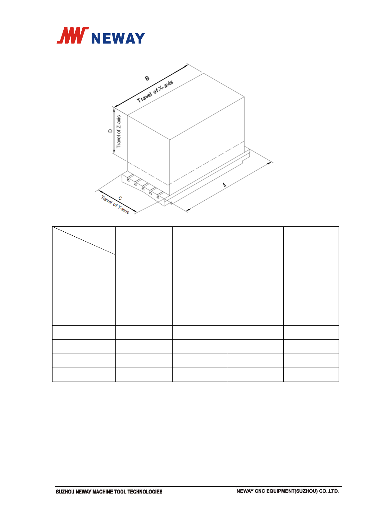
5.8 Travel and maximum workpiece dimension
Parameter
A B C D
Type
VM740 750mm 650mm 420mm 500mm
VM950 950mm 850mm 520mm 560mm
VM1150 1100mm 1000mm 520mm 560mm
VM1160 1100mm 1000mm 600mm 560mm
VM1260 1200mm 1050mm 600mm 600mm
VM1360 1350mm 1200mm 600mm 600mm
VM1580 1500mm 1350mm 800mm 680mm
VM1780 1700mm 1500mm 800mm 680mm
VM1880 1800mm 1700mm 850mm 700mm
Page 38 Total 72
Page 44
Instruction manual Document No.: VM50-9302E
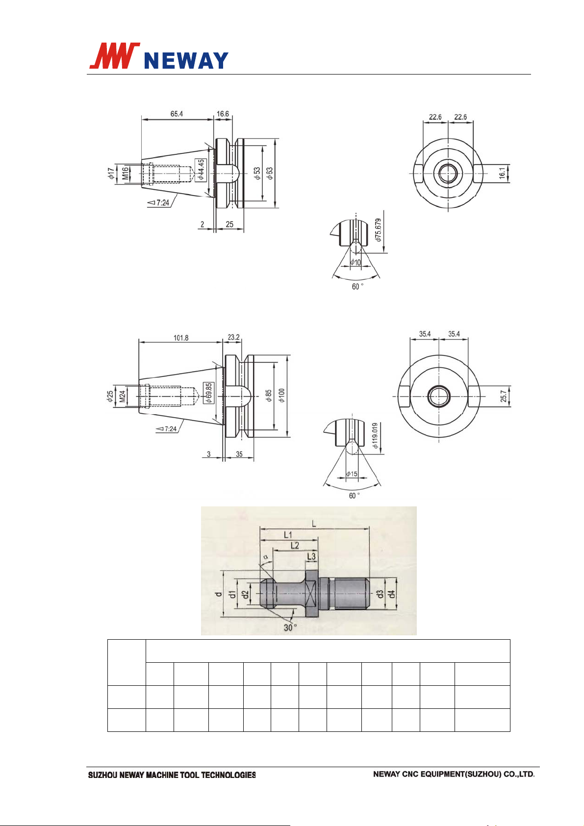
5.9 Tool shank and pull stud bolt dimension
5.9.1 BT40
5.9.2 BT50
Dimension(mm)
Type
L L1 L2 L3 d d1 d2 d3 d4 α Weight
P40T 60 35 28 6 23 15 10 M16 17 45º 0.06
P50T 85 45 35 10 38 23 17 M24 25 45º 0.26
Page 39 Total 72
Page 45
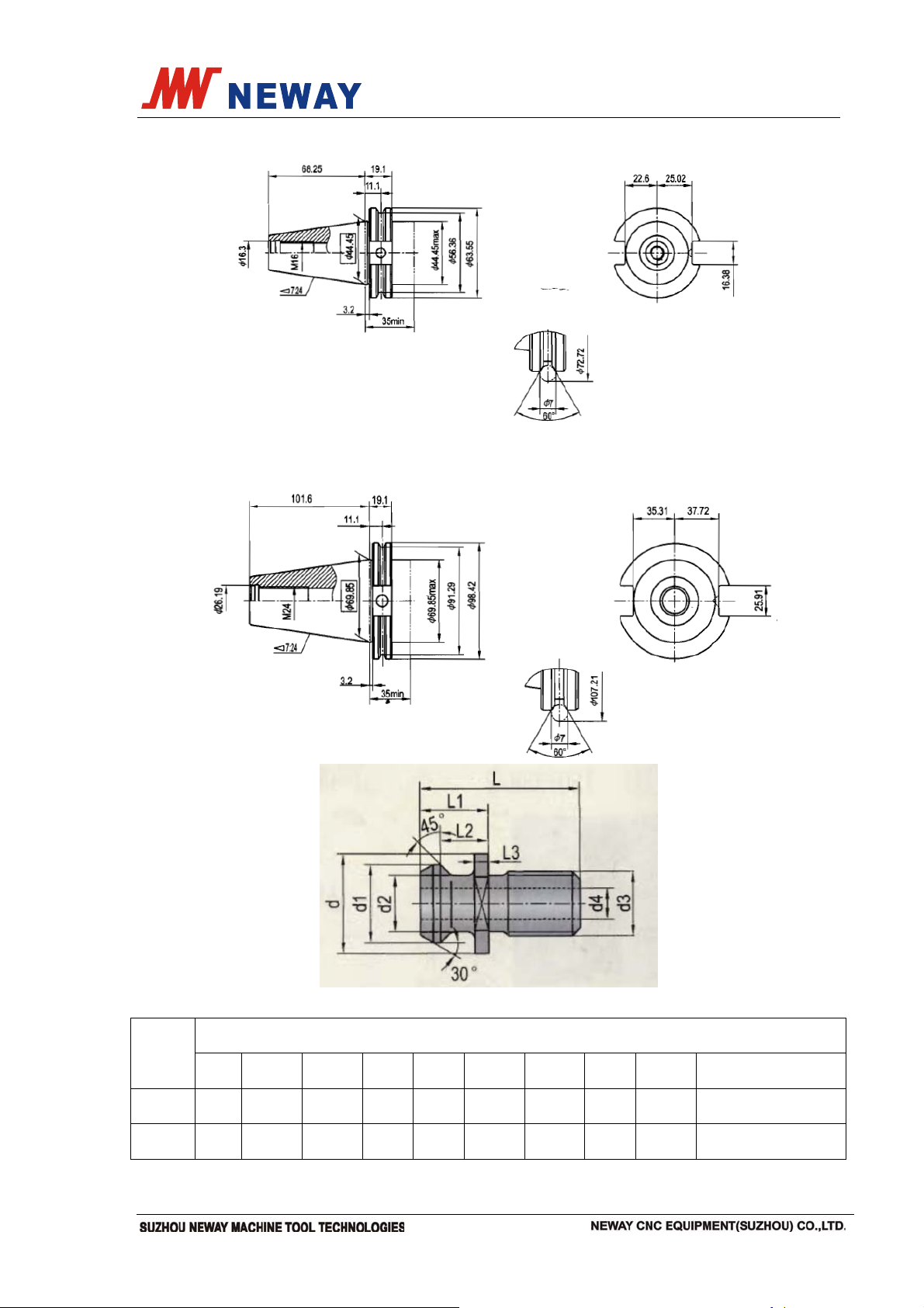
5.9.3 CAT40(optional)
5.9.4 CAT50(optional)
Instruction manual Document No.: VM50-9302E
Dimension(mm)
Type
L L1 L2 L3 d d1 d2 d3 d4 Weight
A40 39 16.4 11.15 3.25 22.5 18.95 12.95 M16 7.35 0.05
A50 60 25.55 17.95 5.25 37 29.1 19.6 M24 11.55 0.2
Page 40 Total 72
Page 46
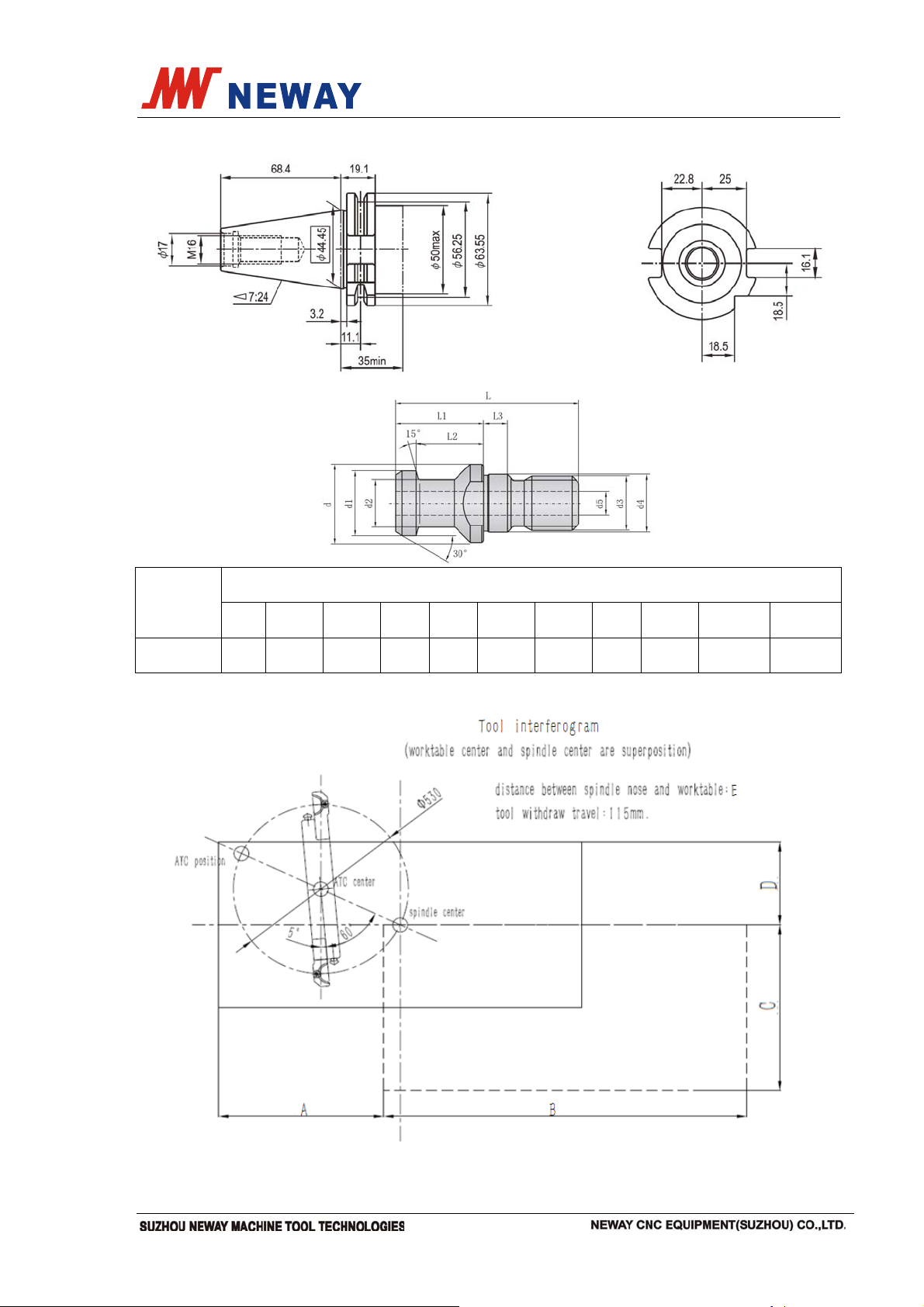
5.9.5 DIN40(optional)
Instruction manual Document No.: VM50-9302E
Dimension (mm)
Type
L L1 L2 L3 d d1 d2 d3 d4 d5 Weight
D40 54 26 20 7 23 19 14 M16 17 7 0.05
5.10 Tool change interference diagram
BT40 tool withdraw travel is 115mm, BT50 tool withdraw travel is 165mm
Page 41 Total 72
Page 47

Instruction manual Document No.: VM50-9302E
参数
机型
VM740 325mm 750mm 420mm 210mm 120-620mm
VM950 425mm 950mm 520mm 260mm 150-710mm
VM1150 500mm 1100mm 520mm 260mm 150-710mm
VM1160 500mm 1100mm 600mm 300mm 150-710mm
VM1260 525mm 1200mm 600mm 300mm 150-750mm
VM1360 600mm 1350mm 600mm 300mm 150-750mm
VM1580 675mm 1500mm 800mm 400mm 150-830mm
VM1780 750mm 1700mm 800mm 400mm 150-830mm
VM1880 850mm 1800mm 800mm 400mm 140-840mm
5.11 Characteristics
5.11.1 Resin casting is adopted to the main castings such as base, carriage, table, spindle
A B C D E
head, column, etc. which is stable in structure. Box-type structure and reasonable rib
collocation ensure high rigidity and high strength and long term high accuracy and
stability.
5.11.2 The motor of each axis is connected to high precision ball screw directly. Ball screw is
preloaded when installed to further improve the transmission rigidity and positioning
accuracy.
5.11.3 Linear rolling-contact guide ways are adopted in all linear axes to damp vibration during
high speed feed, avoid crawl at low speed and keep high accuracy and stability.
5.11.4 Spindle motor via a synchronized toothed belt at a reduced speed ratio. The machine
tool has a strong machining capacity, high accuracy and stable quality.
5.11.5 To ensure the quality of the machine, all the brought-in components are supplied by
branded suppliers.
5.11.6 Full-enclosed protective covers are used to make full use of cooling liquid and to
prevent operator from accidents.
5.11.7 The automatic chain chip conveyor release the working intensity of the operator
dramatically.
Page 42 Total 72
Page 48
Instruction manual Document No.: VM50-9302E
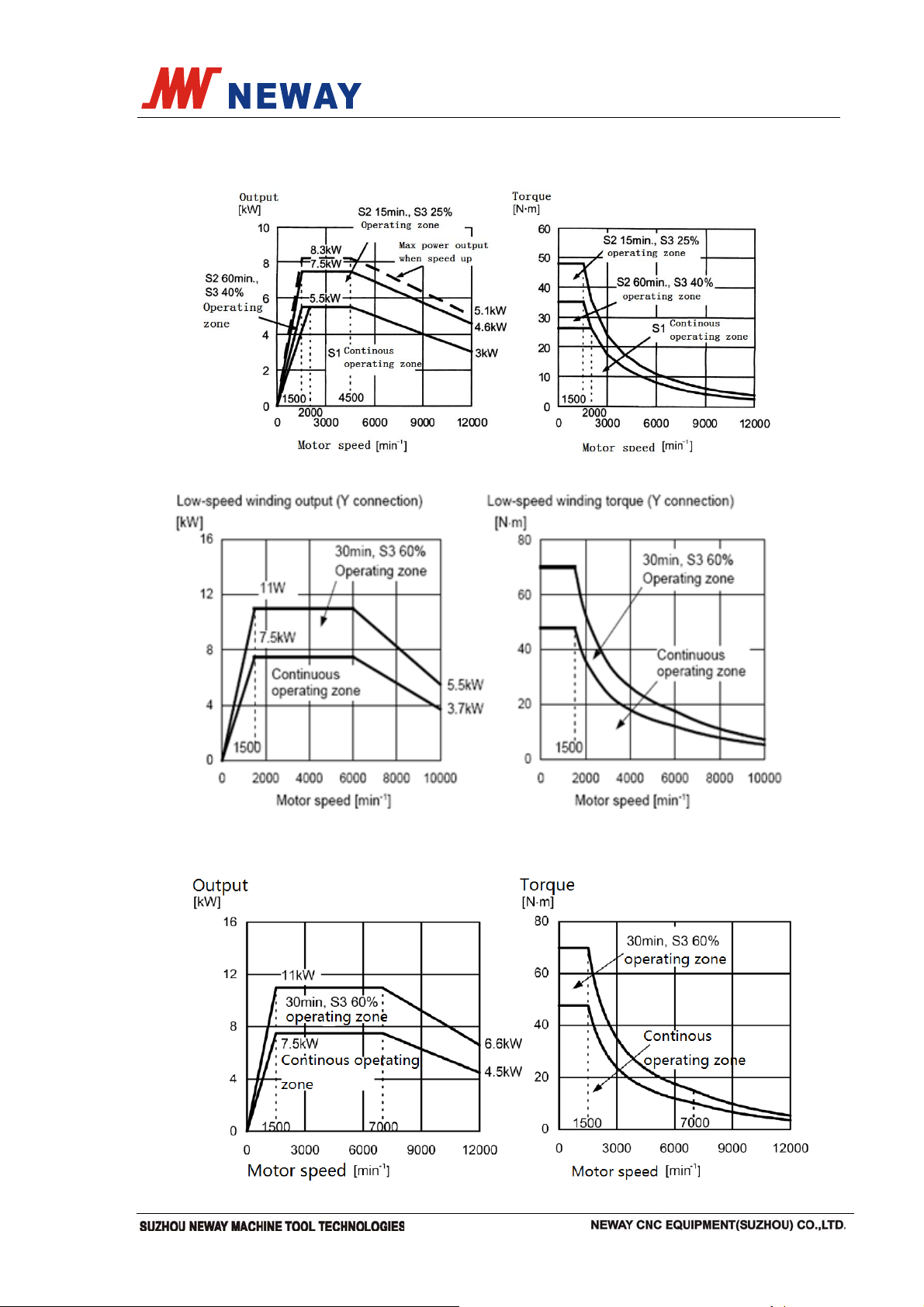
5.12 Output characteristics of spindle motor
5.12.1 Spindle is driven by β6/12000i motor with the following characteristic
5.12.2 Spindle is driven by α8/10000i motor with the following characteristic
5.12.3 Spindle is driven by α8/12000i motor with the following characteristic
Page 43 Total 72
Page 49
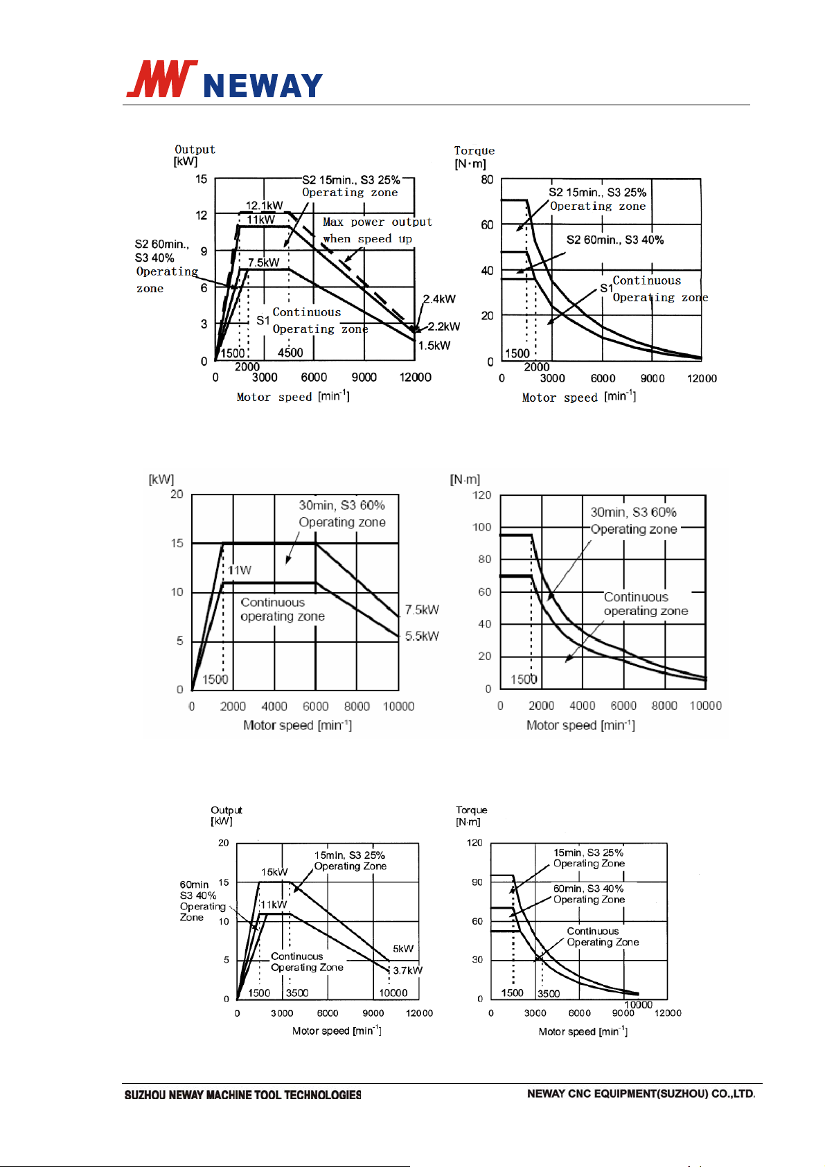
Instruction manual Document No.: VM50-9302E
5.12.4 Spindle is driven by β8/12000i motor with the following characteristic
5.12.5 Spindle is driven by α12/10000i motor with the following characteristic
5.12.6 Spindle is driven by β12/10000i motor with the following characteristic.
Page 44 Total 72
Page 50
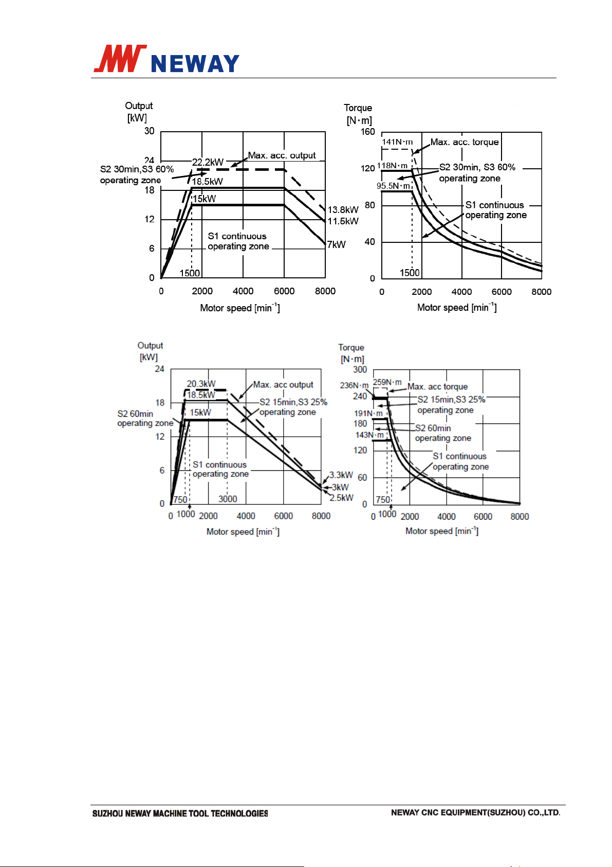
Instruction manual Document No.: VM50-9302E
5.12.7 Spindle is driven by α15/8000i motor with the following characteristic.
5.12.8 Spindle is driven by βiIP30/8000 motor with the following characteristic.
5.13 Transmission system
AC servo motors are used in the three coordinate axes and spindle.
Feed system working principle
The feed drive mechanism drives table (X), carriage (Y), spindle head (Z) to realize
X/Y/Z axis feed motion and positioning via servo amplifying unit, servo motor and ball
screw after receiving instruction from the CNC system. See Feed system schematic
diagram:
Page 45 Total 72
Page 51
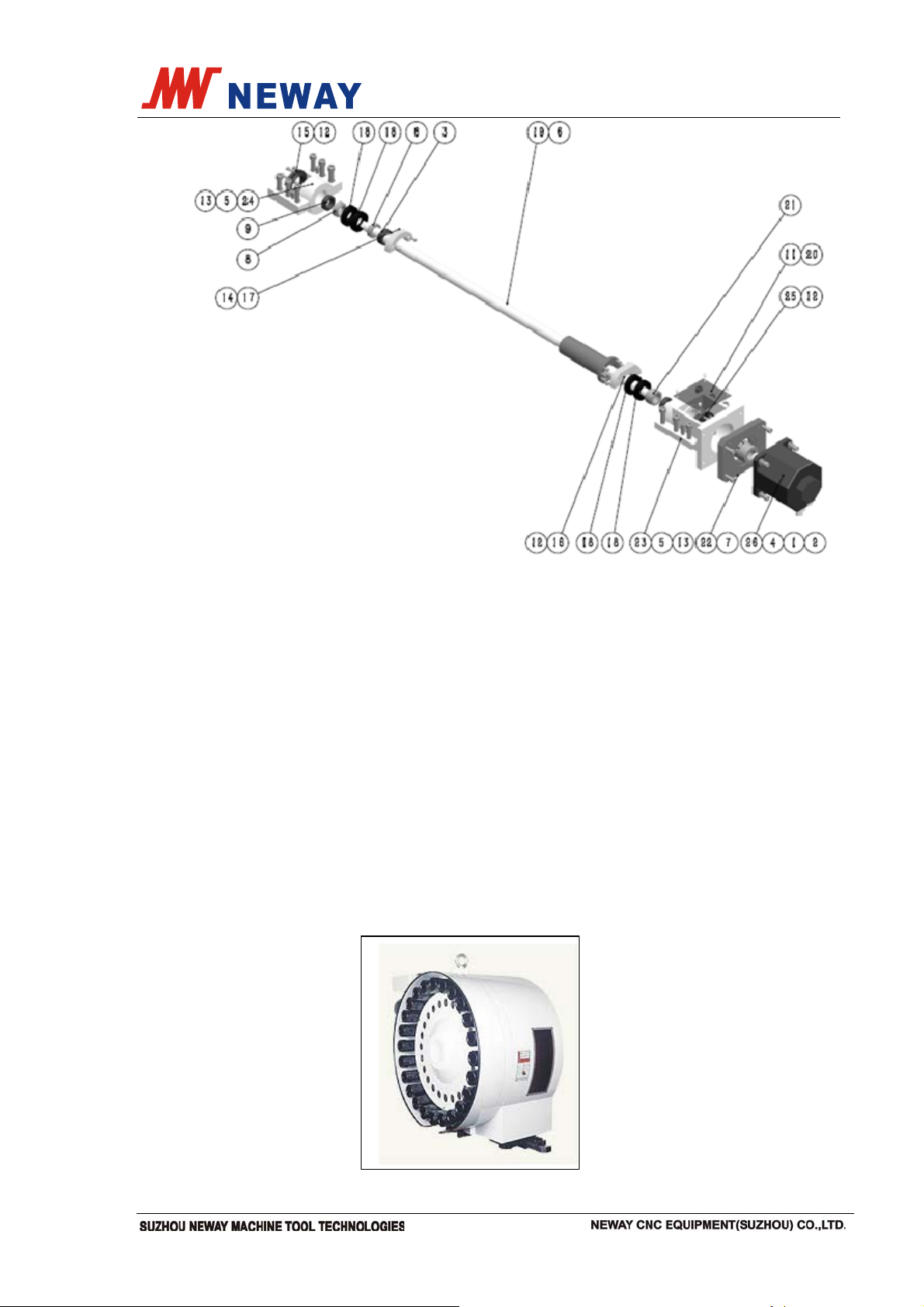
Instruction manual Document No.: VM50-9302E
The drive methods of the three coordinate axes are the same: servo motor is
connected to lead screw via non-clearance elastic coupling that is connected to motor
shaft and lead screw shaft without key, which features easy disassembling and good
concentricity. High speed ball screw is used and pre-tensioned when installed to raise
the accuracy stability and rigidity and ensure the moving accuracy.
The feed system uses semi-closed loop control system. The angle displacement
measuring device in the servo motor detects the displacement of the moving part
indirectly by detecting the rotation angle of motor shaft and feeds the data back to the
comparator that compares the data with the instructed one. The difference of
comparison is used to control the moving part and supplement the displacement until
the difference is in the allowable range of the control system.
5.14 Tool magazine system
5.14.1 Tool magazine outline drawing
Page 46 Total 72
Page 52

Instruction manual Document No.: VM50-9302E
5.14.2 Tool magazine working principle
Tool magazine drive system, including tool magazine, manipulator, etc. is used to
realize the tool change of the machining center. When the CNC system sends out the
instruction, tool change will be carried out automatically.
The indexing and tool change motion are realized by cam device. For details,
seeing the Tool Magazine Instruction Manual.
Tool magazine can hold 20 or 24 tool, tools are managed by PMC(Programmable
Machine Controller). Tool needn’t coding and switch and tool is selected in sequence.
Every tool has a fixed tool station and is set by the operator. If the tool station or station
number is changed, it should be reset in CNC. For safety reasons, spindle tool number
is set 00, that is to say spindle has no tool. The tool to be machined is placed in each
station.
Like axis, tool magazine also has reference point. When machine tool is powered
off, or emergency stop button is released, execute tool magazine return to zero position
and then tool station No. 1 (T01) is in the tool change position. Tool change is divided
into two circumstances: spindle has tool and spindle has no tool. In the former
circumstance, the tool station to be changed is the xx tool before tool magazine acts;
while in the latter circumstance, the tool station to be changed must be empty, that is to
say that it corresponds to xx tool station number of xx tool number in spindle. For safety
reasons, move X-axis in the negative limit position and Y-axis in the positive limit
position when spindle orients in tool change process.
Tool change sequence: spindle move to tool change point → tool magazine find
tool → tool pocket overturn → ATC seize tool → spindle unclamp tool → ATC draw tool
→ spindle huff → ATC turn and change tool → ATC load tool → spindle clamp tool →
ATC back to zero position→ tool pocket back to original position
Page 47 Total 72
Page 53
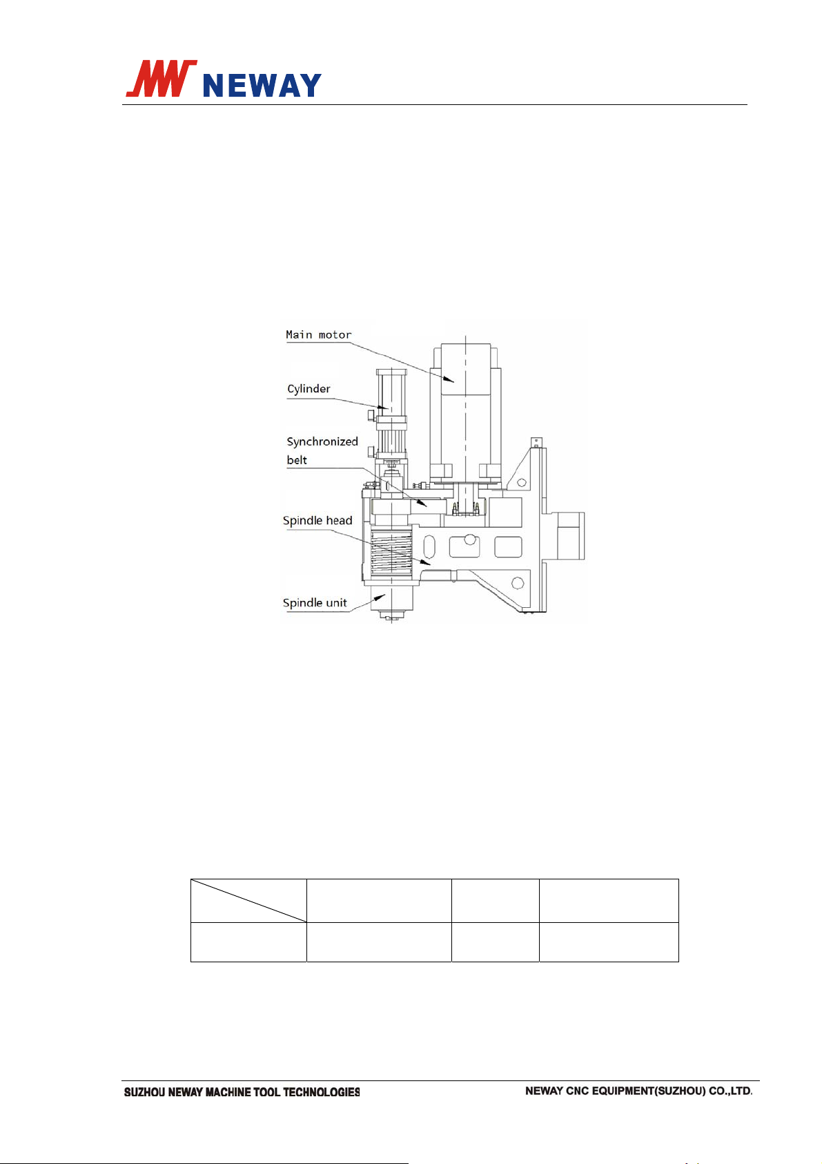
Instruction manual Document No.: VM50-9302E
5.15 Spindle transmission
5.15.1 Spindle transmission principle
The power is transmitted from motor to spindle via a synchronized toothed belt.
To replace the transmission belt, the specification and supplier of the product
should be the same with the original one. The steps to replace the belt is as follows:
take down the connecting air pipe of the cylinder → take down pneumatic cylinder →
take down cylinder rest → replace belt → install cylinder rest → install pneumatic
cylinder → install the connecting air pipe of the cylinder → tension the belt. For the
spindle head assembling schematic diagram,see the following picture.
To tension the belt, loose the two adjusting screws, move the spindle motor plate
and then lock the nut in the plate. If the belt is too tight, the load to the spindle bearing
will increase and the service life of the tool will be reduced. Guard against oil or dirt
when replacing the belt.
Automatic clamping tools system inside spindle. Use pull rod and Belleville spring
clamp the tool. The standard of tool is 40# for this machine. Please attention on
different standard of tools and blind rivet. Each model spindles have specific
unclamping force and blind rivet; please reference to above parameter list. During
unclamping dry compressed air will through spindle to clean taper hole of spindle.
Parameter table:
Model Item Unclamping force Push-out Tool shank type
40# 3.5t 0.4~0.7mm
Page 48 Total 72
BT/CAT/DIN
Page 54
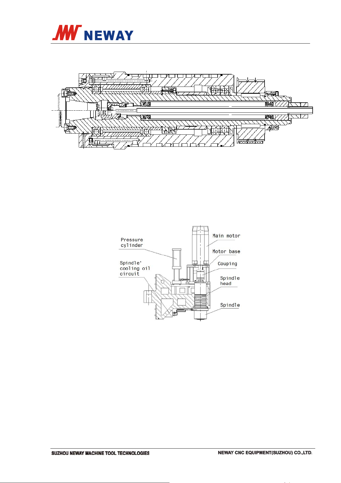
Instruction manual Document No.: VM50-9302E
5.15.2 Spindle’s construction drawing
5.15.3 Coupling spindle transmission principle
The directly coupled spindle is applied for the machine tool. The power is
transmitted from main motor to spindle by coupling. The spindle need to be dismantled
when malfunction happens, please pay attention to the positioning pin on motor base.
Make sure the coaxality of spindle and motor is less than 5μm when reinstalled. The
assembly drawing of spindle is as follows:
Automatic clamping tools system inside spindle. Use pull rod and Belleville spring
clamp the blind rivet of tool. The standard of tool is 40# for this machine. Please
attention on different standard of tools and blind rivet. Each model spindles have
specific unclamping force and pull stud; please reference to above parameter list.
During unclamping dry compressed air will through spindle to clean taper hole of
spindle. Direct connection spindle has special clamping structure, please contact
manufacturers when breakdown. The spindle’s construction drawing:
Page 49 Total 72
Page 55
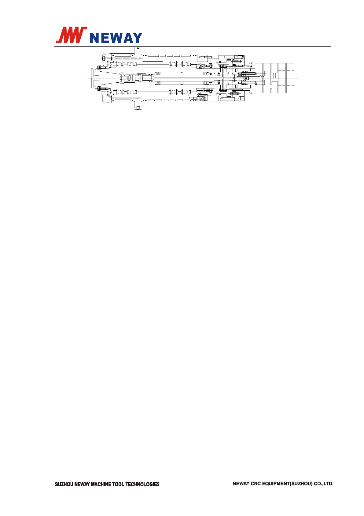
Instruction manual Document No.: VM50-9302E
5.15.4 Spindle specification
The machine tool use BT40 or BT50 spindle, CAT40 and DIN40 are optional.
5.15.5 Coolant through spindle (optional)
For special material like aluminum alloy, titanium alloy and SS steels or for special
process like small diameter drilling, deep drilling or U drill is necessary, user may need
to equip the machine with coolant through spindle function. The spindle is specially
made for coolant through with through bore in tool pull rod, pull stud as well as the tools.
A rotary connector with high speed seal performance works at the end part of the
spindle as a transition device and the mandril rotates together with the spindle. The
shell part is immobile and in connection with the waterway. The spindle is supported
with its own water tank and high pressure filtering device of 20μmesh. The mesh is
replaceable at wish. The water tank filters the coolant and is the assurance of adequate
liquid flow, working pressure and with the help of a high pressure pump.
5.15.6 ZF gearbox transmission
1) ZF gearbox principle and function
The motor connects the import of ZF gearbox directly. ZF gearbox export end
transmits the power to the spindle via gears. Solenoid valve operates the gearbox with
two speed transmission of 1:1 and 4:1. When working at 4:1 transmission, the spindle
speed is lowered to 1/4 and the torque increases by 4 times accordingly to perform
torque cut.
2) Main parts
Connecting parts: driving hub(1),adapter plate(2)with radial shaft seal,(3)and
hub bearings(4)(optional),
housing: gearbox housing(5),
import: sun gear(6),ring gear(7),ring gear bearing(8),
export: bearing housing(9),export bearing(10,11),export shaft(12),radial shaft
seal(13),planet gear carrier(14),axial bearing with springs(15)
Shift mechanism: sliding sleeve(16),shift fork(17),brake disc(18),
Shift components: Solenoid(19),selector shaft(20),adapter plate(21)。
Page 50 Total 72
Page 56
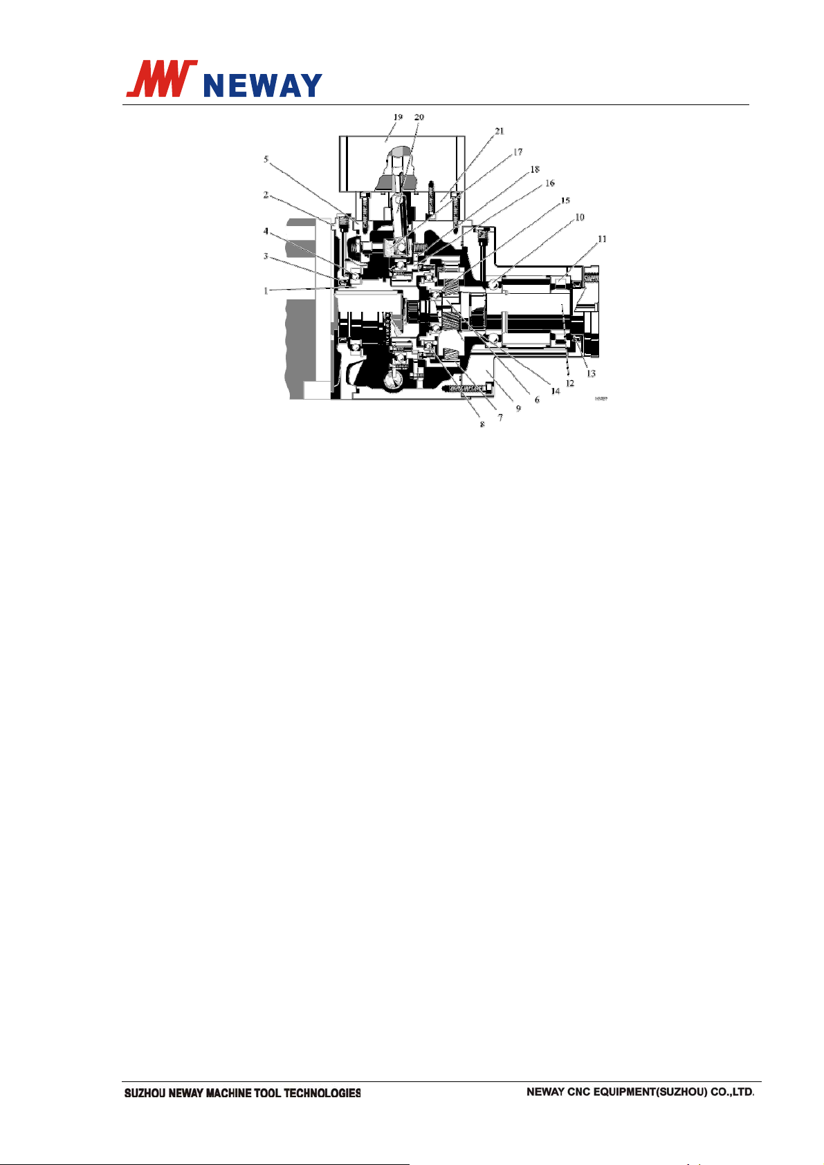
Instruction manual Document No.: VM50-9302E
3) Shift principle
1:1 transmission gear:
a) Selector shaft drives shift fork (20) to move left (17) selector shaft (20) moves
leftwards with shift fork (17);
b) Sliding sleeve (16) moves leftwards, the outer gear breaks away with braking disc
(18);
c) Alligatoring ring of sliding sleeve (16) moves along the denticulate ring;
d) Sliding bush (16) moves to left (1) sliding sleeve (16) attaches with denticulate
drive hub when moving leftwards;
e) After shifting,sliding sleeve (16) joggles with drive hub (1) and ring wheel (7) at the
same time;
f) Alligatoring ring of drive hub (1) joggles with sun gear (6);
g) The whole planet mechanism allies to transmit the power through the export shaft
(12) while rotates with drive hub (1);
h) The 1:1 transmission is realized.
4:1 transmission gear:
a) Shift fork (20) moves rightwards with shift fork. Refer to illustration;
b) Sliding sleeve (16) moves rightwards and denticulate ring (18) joggles with braking
disc;
c) Alligatoring ring of sliding sleeve (16) slides along denticulate ring wheel (7);
d) Sliding sleeve (16) breaks away the drive hub (1) while sliding rightwards;
e) After shifting, sliding sleeve (16) joggles breaking disc (18) and ring wheel (7);
f) Alligatoring ring of driving hub (1) joggles sun ear;
g) The power is transmitted from drive hub to sun gear and to the export shaft (12)
Page 51 Total 72
Page 57
Instruction manual Document No.: VM50-9302E
through planet gear mechanism and planet gears carrier;
h) 4:1 transmission is realized.
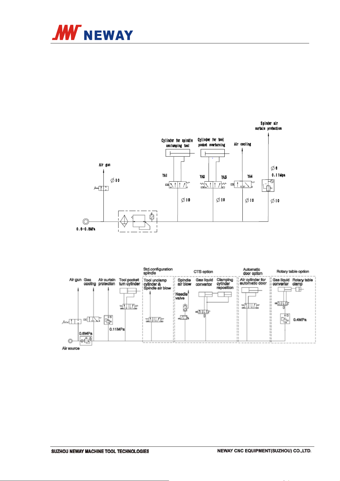
5.16 Pneumatic pipeline
5.16.1 Pneumatic schematic diagram (standard)
Tool clamping, tool unclamping and spindle air blow are realized by compressed air.
The air pressure of the system is 0.6~0.8MPa.The compressed air is delivered to each
implementing point via filtered. For the pneumatic principle, see the picture below.
5.16.2 Pneumatic schematic diagram (optional)
5.16.3 The requirement of air source
The flow of the air source is required to be more than 280L/min, and the pressure
0.6~0.8MPa. The pneumatic system is equipped with pressure switch. Alarm appears
as the pressure is less than 0.4MPa and disappears automatically as the pressure
rises.
The water removed by the filter is drained from the bottom of the filter. Users
should check if the drain valve is jammed at regular intervals.
Page 52 Total 72
Page 58
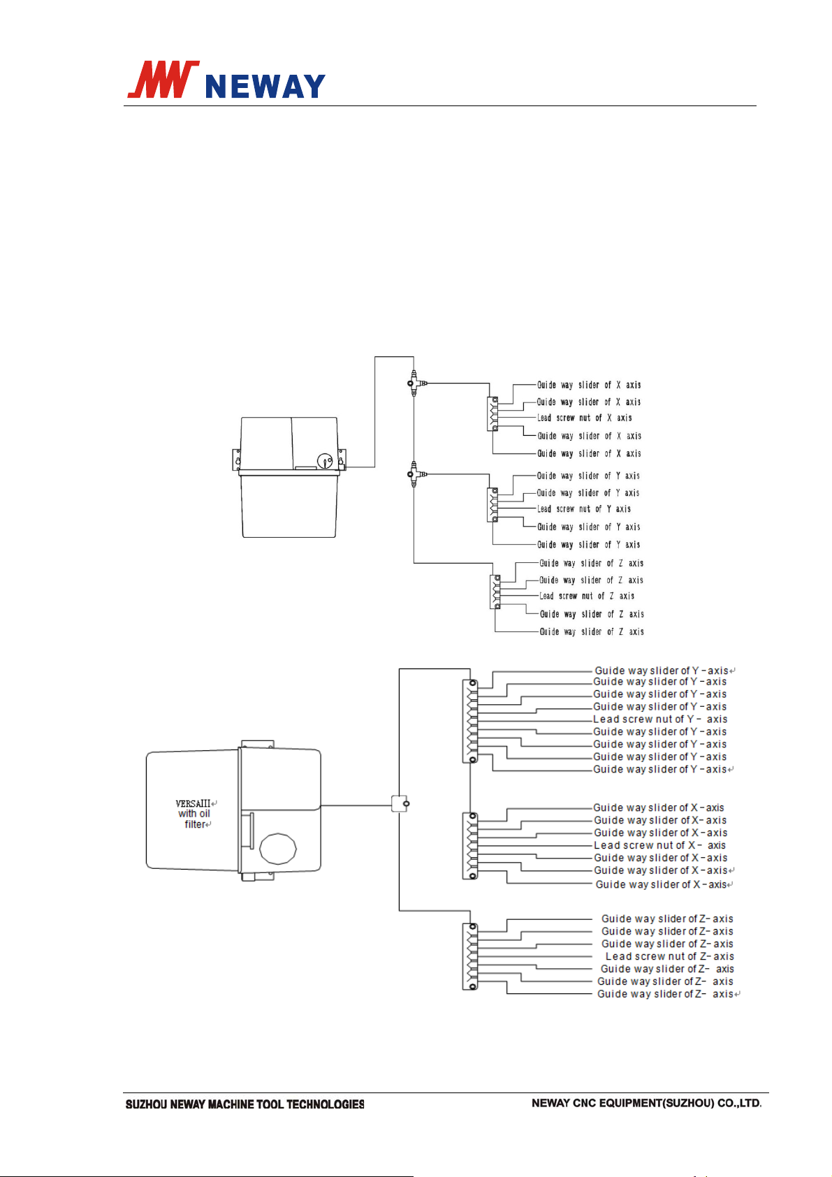
Instruction manual Document No.: VM50-9302E
5.17 Lubricating system
5.17.1 Lubricating of guide ways
The lubricating oil is supplied to the moving parts by the lubricating pump at fixed
time and quantity to lubricate the three coordinate guide way surface: base—carriage
guide way surface, carriage—table guide way surface, spindle head—column guide
way surface and lead screw nut. When the machine tool is powered on, lubricating oil
pumped by the lubricating pump at a reduced speed inpours into every lubrication
points and ball screw nut. The timing lubricating device is equipped with oil level switch.
When the lubricating oil level is below the set height, alarm will appear. Fill the tank with
lubricating oil every two weeks. For the lubricating principle, see the picture below.
(Linear way with 2 rails)
(Linear way with 4 rails)
Page 53 Total 72
Page 59
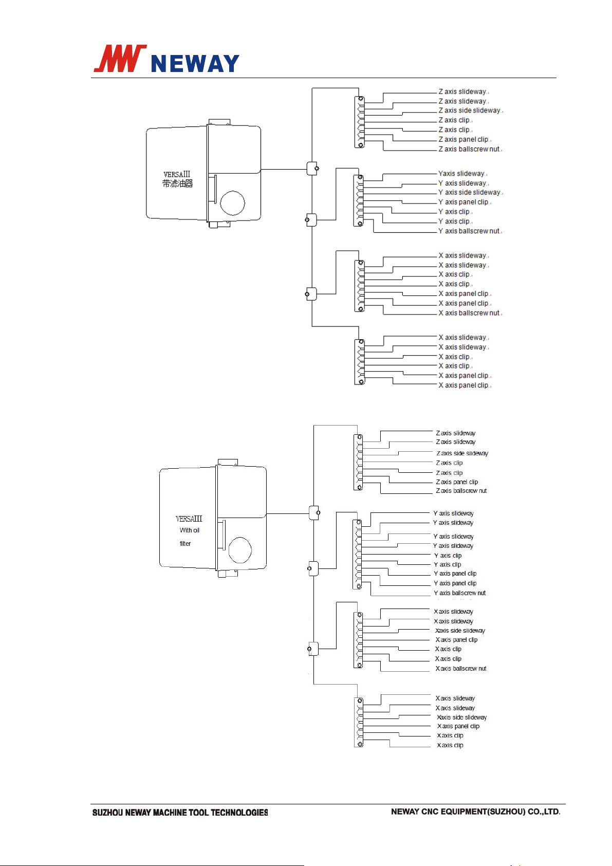
Instruction manual Document No.: VM50-9302E
(Box way with 2 rails)
(Box way with 4 rails)
Page 54 Total 72
Page 60
Instruction manual Document No.: VM50-9302E
Choose the lubricating oil with approximate viscosity as season and temperature
change. The oil with low viscosity will result in the malfunction of exhaust valve. It’s
recommended to use 68# hydraulic guide way oil.
5.17.2 Utilization of high speed grease
Quantitative NBU15 high speed grease, which is able to endure abrasion and
temperature rise and won’t flow away in high speed, is filled in the spindle bearing and
lead screw bearing. User needn’t replace it until overhauling the machine.
5.18 Cooling system
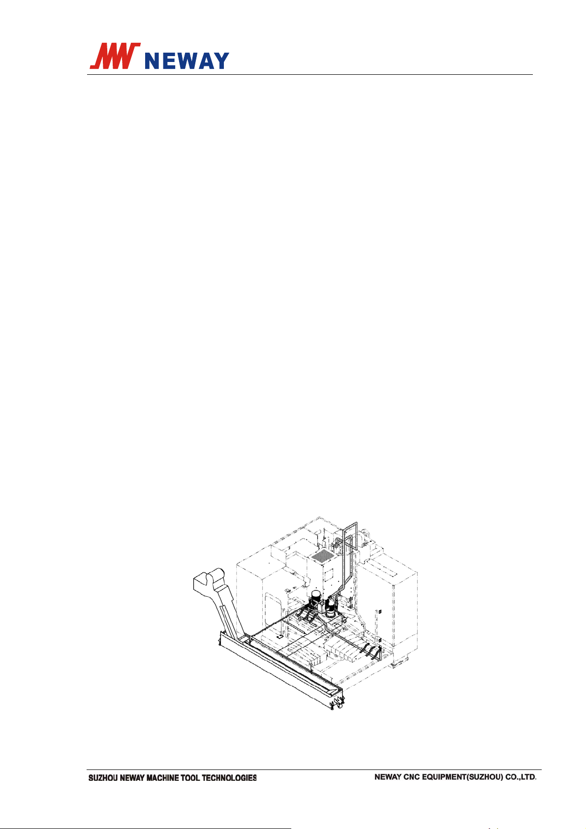
5.18.1 Workpiece cooling and chip removal
The cooling system of this machine covers:chain type chip conveyor and cooling
tank. The chain chip conveyor collects metal chips automatically and helps the machine
operator to work a lot easier. The coolant tank is to be filled with mineral oil or
emulsified mixture. The coolant is pumped to the column then to the spindle hose and
sprays through the nozzle. The flow is adjustable by turning nozzle spray and valve.
The coolant gone through workpiece flows to the coolant tank to be recycled by
deposition. The coolant pump is operated and controlled by the buttons on the control
panel or processing codes.
Coolant through outlets are placed around spindle nose. The pump is controlled by
the buttons as well as controlled by M code in the program for easier cooling. Each
sprayer is operated by ball valve for flow and direction adjusting. Chip removing pipes
are situated at the bottom part of the machine,6 sprayers work for this purpose with
high pressure to enable the chips be flushed away quickly and cool down workpiece so
that the thermal deformation in the workpiece is avoided. Chip removal pump is also
controlled by the buttons on control panel and by M code.
5.18.2 ZF gearbox cooing (optional)
When the machine is equipped with a ZF gearbox, it is necessary to add a ZF
Page 55 Total 72
Page 61
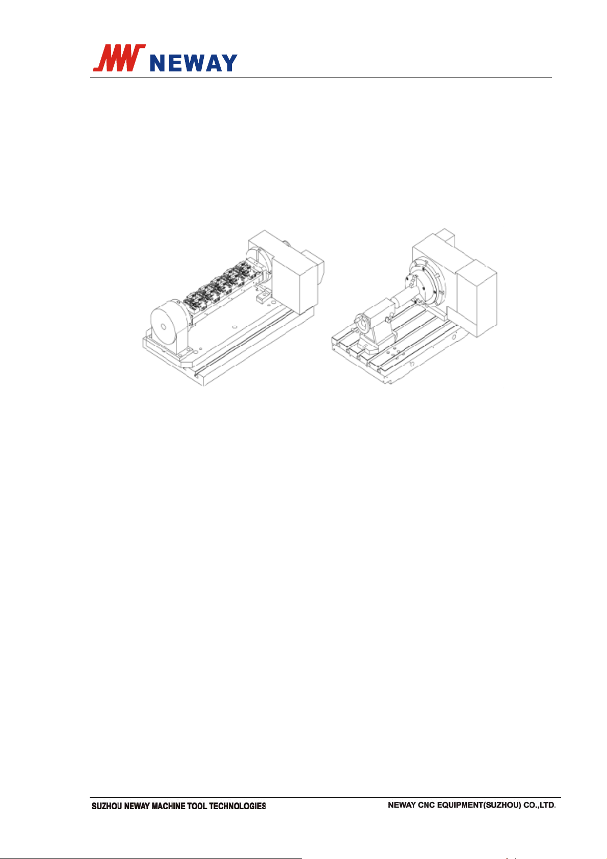
Instruction manual Document No.: VM50-9302E
gearbox cooler. The cooler cools down and lubricates the gears and bearings via
circulated coolant.
5.19 CNC rotary table(optional)
By using a rotary table, the machine can be 4 axes synchronically operational and
meet the requirements of machining with indexing rotation. If chuck and tailstock are
also equipped, circular and cylindrical parts could be processed. For example, helix
slots are workable under 4 axes function. CNC rotary table can be useful when the
workpiece need to be processed in multi-angle or multi-surface.
5.20 Utilization
The machining accuracy, efficiency and automatization of the machining center
depend on the quality of the mechanical part and the performance and stability of the
CNC system. Besides, in order to make full use of the machine tool, it’s essential to
have a full knowledge of the characteristics and machining technology of the machine
tool and use the machine tool reasonably. The following operating methods introduced
are for reference.
5.20.1 Operation
The most operation can be realized by pressing the keys and buttons on the
operating panel and control panel (For details, see Instruction Manual Electrical Part).
Only the following two kinds of operation should be carried out manually.
1) Unclamp the tool manually
In most circumstances, tool is loaded to the spindle by manipulator. In special
circumstances, it’s needed to load the tool to spindle by hand by pressing the button at
the right side of the spindle head in manual mode. (When the indicator light lights, the
tool is unclamped and vice versa.)
Note: The button is invalid when the machine is in machining state.
2) Tool magazine manual control
To facilitate the adjusting of the machine, a group of keys on the protective cover at
the lower right of tool magazine are designed for manual control of the tool magazine.
For the detailed operation, see Instruction Manual Electrical Part.
Page 56 Total 72
Page 62

Instruction manual Document No.: VM50-9302E
5.20.2 Select the workpiece for machining
The geometry and dimension of the workpiece should be in accord with chuck and
the travel of the machine tool. To raise the economic interest, consider the following
principles:
1) Small batch production when the workpiece is put into production repeatedly
To machine a workpiece by machining center, the time of prepared procedure such
as technology preparation, programming, etc. is long, but the tool, fixture, technologic
documents and program sheet can be repeatedly used. Therefore, when the workpiece
is put into production after test cutting, the production cycle and machining time will be
reduced dramatically.
2) The machining batch should be more than the economic lot size
Compared to the common machine tool, the flexible working time of a single
workpiece of a machining center is shorter while the adjusting time is longer, so it’s
uneconomical if the batch of the workpiece is small.
Machining Center Preparation Time –
Common Machine Tool Preparation Time
Economic = ———————————————————————————————————————
Lot Size K(Machining Time of a Single Workpiece
in a Common Machine — Machining Time of
a Single Workpiece in a Machining Center)
Thereinto, Machining Center Preparation Time = Technology Preparation Time +
Debugging time
Debugging time = Machine Tool Adjusting Time + Workpiece Program Test Run Time +
Test Cutting Time + Fixture and Auxiliary Device Validating Time
Here, only the adjusting time is part of machine tool starting time. For the
workpiece needing repeated production, the time of technology preparation and
program preparation should be divided by repeated production time. The machining
time of a single workpiece in a common machine is the summation of each NC
machining process time.
The compensation factor K should be at least 2, considering that the machining
center is much more expensive than the common machine tool. K should be larger as
the acquired skills improved.
1) Try best to do the integrated machining such as milling, boring, drilling, reaming,
tapping, etc.
2) The diameter of the workpiece for precision boring shouldn’t be more than 130
mm for the maximum tool change capacity of ATC device is 130 mm. To machine
the bigger hole, load and unload the tool manually or use circular interpolation
method to mill the hole, but the precision is lower.
Page 57 Total 72
Page 63

Instruction manual Document No.: VM50-9302E
3) The geometry and dimension of the machine tool should be in accord with the size
of table and travel.
4) Consider the balance of plant capacity.
5) The small but with complex geometry workpiece that is unable to be machined in
common machine tool or uneasy to obtain a stable machining accuracy.
5.20.3 Decide which part to machine
1) Before machining, determine which working procedure should be done in the
machining center and button down the relationship of the procedure and its last
and next one. For example, which kind of datum face and hole should be machined
before the workpiece is machined in the machining center and what working
procedure, allowance, etc. are left after the workpiece is machined in the
machining center.
2) Don’t use the machining center if other machine tool is more suitable and efficient
to machine the workpiece.
3) Decide whether to finish the machining once or twice in a single setup according to
the tool number needed and the requirement of workpiece accuracy and heat
treatment.
5.20.4 Compile the process chart
1) The format of the process chart is manifold. The user can develop an appropriate
format according to the production custom and need. The process chart is the gist
of program list, tool adjusting list and machine tool adjusting and the working
content of the operator.
2) Be familiar with the relevant stipulations of the use of machine tools
a) The setting of each coordinate origin, the direction of each coordinate axis, the
setting of workpiece coordinate system and the travel range.
b) Range of spindle speeds and S instruction.
c) Feed range and f instruction.
d) Tool and T instruction, tool change instruction.
e) Cutting criterion.
f) The working principle and instruction list of CNC system.
g) The machining characteristics and operating methods of the machine tool.
h) The approaching distance of tool (the distance from tool nose to the surface to be
machined after rapid traverse ).
It’s recommended that:
a) Drilling, boring and reaming on the processed surface: 1~3mm.
b) Drilling, boring and reaming on raw casting surface: 5~8mm (decided by the
allowance of the surface).
c) Tapping: 5~10mm.Milling: 5~10mm.
Page 58 Total 72
Page 64

Instruction manual Document No.: VM50-9302E
5.20.5 Decide the sequence of working procedure
As the many process steps and tools are needed in the machining center, the
reasonable sequence arrangement of the working procedure is important to the
machining accuracy, machining efficiency and quantity of the tool. The sequence of the
working procedure is influenced by the following factors:
1) First do the heavy cutting and roughing, then the machining with little heat
productivity and low accuracy requirement (e.g. drilling a small diameter hole,
tapping, etc.), and finally finishing.
2) Machine the workpiece in the adjacent position first to shorten the idle travel
distance. Consider the tool moving track to reduce the displacement of each
coordinate axis.
It’s recommended to arrange the working procedure according to the following
sequence:
Mill the large end face (rough milling and finish milling is done independently) →
rough boring/semi-finish boring → end mill machining → drilling → tapping → hole
finishing (reaming, boring, finish milling)
5.20.6 Tool selection
The tools used in the machine include universal cutter and universal connecting
toolbar. Select the appropriate tool according to the requirement of machining and the
process chart, determine the tool position in the tool magazine (mark the tool station
number) and map out the tool card (used for tool preparation, adjustment and loading).
Note 1: if the tool length and deviation value can’t be decided at once, adopt the
following two methods:
1) First, set a nominal dimension, and then add tool compensation when
programming. Program with nominal dimension and modify the dimension by tool
compensation value (the difference value of nominal dimension and measured
value).
2) Tool length is not written in the tool card and is zero in the program. Designate a
tool compensation number for each tool and input the measured tool length in the
tool compensation data list after the tool is prepared.
Note 2: Tool length, which is the tool compensation value or the measured length in the
working area after tool is loaded in the spindle, is the axial dimension from cutting edge
to spindle end face.
For the specification and dimension selecting of the toolbar, please refer to the
production sample provided by the toolbar manufacturer.
Special tools are used if the requirement of machining is special. Consider the
interchangeability of each kind of tool when selecting the tool, e.g. end milling with
circular interpolation besides boring can be used to machine the large sized hole.
Page 59 Total 72
Page 65

Instruction manual Document No.: VM50-9302E
Therefore, the user should have a full knowledge of the tool series and performance of
the machine tool and select the tool flexibly.
5.20.7 Cutting data determination
1) Take the cutting data in the Tool Cutting Manual for reference and modify it
according to the on-site experience. Use the data in the cutting database as much
as possible as the development of automatic programming.
2) Modify the data according to the rigidity of the machining—technology system
(tool—workpiece—fixture—machine tool).
3) Modify the data considering tool service life. In medium and small batch production,
try best not to sharpen or replace the tool in a batch to reduce the adjusting time.
To reduce the machining time of heavy load cutting tool, e.g. end mill, rough boring
cutter for deep hole, etc., use larger cutting data to shorten the incorruptibility of the
tool to half or one third.
5.20.8 Tool preparation
Prepare the tool according to the technologic card, the steps are as follows:
1) Select the toolbar and cutter according to the card;
2) Sharpen the cutter or the boring cutter head;
3) Assemble the cutter head, toolbar and end taper and label it with the tool number;
4) Adjust the tool length to the set dimension, measure the tool length and record it in
the tool card. For high precision cutting, e.g. finish reaming, finish boring, etc. do
test cutting according to the selected cutting data and modify the adjusting data
according to the test cutting result.
5.20.9 Compile the “machine tool adjusting list”(it can be included in the process chart)
1) Designate the group number and the concrete tool compensation value when using
tool radius compensation and tool length compensation.
2) The application of on-site selecting switch(e.g. mirroring switch, block skipping
switch, select to stop switch, etc.)
3) The cooling method of the workpiece (which kind of coolant should be used)
4) Precautions of tool number setting, etc.
5.20.10 Coordinate calculation and working track diagram
Do the calculation according to the drawing. Calculate the input data of the CNC
system according to the working path and allowable programming error. The moving
path is simple for the point machining, simple dimension conversion is sufficient for the
programming, which can be further simplified if a reasonable workpiece coordinate
position is selected and incremental method and absolute method are flexibly used.
Numerical calculation is the premise of programming for contour machining and it has a
close relationship with the workpiece contour and interpolating method of the CNC
system. The linear—circular interpolation system simplifies the calculation of the
Page 60 Total 72
Page 66

Instruction manual Document No.: VM50-9302E
workpiece composed by line and arc. Linear or circular approximation is used for the
workpiece composed by other curves. For the complicated tool motion, tool path can be
drawn for the programming.
5.20.11 Compile the program list
For details, see the Programming Manual.
5.20.12 Program input
There are many ways to input the program, among which, using the MDI device is
a simple way, but it spends more time and take up the machine starting time and it’s
error-prone for the long program.
5.20.13 Dry run
To check the program, test run the program after adjusting the machine. The
methods for test run are as follows:
1) Press “MACHINE LOCK” key to check the program.
2) Press “MST LOCK” key to check if the axial movement meets the requirement. To
check the moving track, press “DRY RUN” to shorten the running time.
3) Press “Z-axis Lock” key to check the M, S and T functions.
4) Check if tool compensation and the sign are appropriate. Check if interference
exists in the motion of tool and each component or fixture.
5) The test run time shouldn’t be long. Try best to reduce the malfunction especially
the damage to the machine tool, workpiece, or tool.
5.20.14 Test cutting
When machining, check if the cutting data (can be modified by the OVERRIDE
button), machining sequence and too path are reasonable. Modify the program after the
automatic cycle is over. Check the machining accuracy of the workpiece and take
measures such as finish adjusting tool, modifying tool length and radius compensation,
editing the program, etc. to meet the accuracy requirements.
For the safety concerns, reduce the rapid traverse speed (in control of RAPID
FEEDRATE key).
5.20.15 Does after machining
The modified program after test cutting can be used for workpiece machining in
batches. After machining, store it in the memorizer. The program validated and modified
after production should be saved in the floppy disk or memory card for further use. In
addition, the technology document, program list, etc. should be amended for further
use.
6 Mechanical maintenance
To use the machine correctly and to keep the machine from problems, you need to
maintain the machine periodically. It is very important to keep the machine clean
because the dust, moisture and oil will erode the mechanic and electric parts.
Page 61 Total 72
Page 67

Instruction manual Document No.: VM50-9302E
Clear away oil, coolant and dirt in the machine first, cover all outlets with cocks so
that no detergent enters into the machine. Clean the machine with detergent and
remove all the covers and cocks. Check leakage on hydro pipes, loose connection on
connectors or any wear out on connectors and make repair. Clean the machine with
clean cloth without hair. The cleaning job includes cleaning and vacuum de-dust.
Never use compressed air, high pressure water or chemicals to clean the machine.
Please note the following:
6.1 Lubrication System
Lubrication pump and electric controller supply lubrication service. The pressure
controller and low oil feed-back ensure lubrication intervals.
If not used for a long time, force the pump to lubricate the machine manually. If
launch the machine in this case, ball screw will wear dramatically, even burn up. Under
the case that the machine did not work for a long time, lubricating pump should be
manual controlled to supply lubricating oil before conducting.
6.2 Hydraulic System
Medium of hydraulic system:#32 hydro oil (winter), #46 (summer). For a new
machine, change the oil after 3 months. Then every 6 months.
6.3 Pneumatic system
Maintenance period of pneumatic system usually is long. If the element of filter
turned dark in the daily examination, replace the filter element. If find the pressure of
inlet and outlet of filter large , it reveals blocking, replace the filter element.
6.4 Cooling System
6.4.1 Coolant tank
Coolant must always be clean and clear, free of foreign objects. If it is found that
the liquid becomes muddy, change it immediately. Decide coolant according to different
material to cut. Recommend to clean the coolant tank every month.
6.4.2 Oil cooler
The oil cooler has a definite volume. Fill the cooler up at its first use. The
replacement period of coolant is 3 months. The air filter net on the cooler need to be
cleaned once a week.
Page 62 Total 72
Page 68
Instruction manual Document No.: VM50-9302E
A
6.5 The detail of lubrication oil and coolant
Lubricating
1
2 Lubricant pump
point
ri composition
element
Inspection period method Volume/type Medium grade
6 months
Lower than
the liquid level
warning line or
alarm warning
Fill to the liquid
level line
2L
4L
VM740
VM950
VM1150
VM1160
VM1260
VM1360
VM1580
VM1780
VM1880
ISOVG68
3 Coolant tank
4 Oil cooler
6.6 Note
1) Never use this machine to cut non-metallic material like graphite, stone, plastic or
wood as well as soft materials or low flammable material like Magnesium alloy.
Lower than the
red liquid level
warning line
Lower than
the liquid level
warning line or
alarm warning
Fill to the liquid
level line
Fill to the
liquid level line
>160L VM740
>300L
>350L
>400L
VM950
VM1150
VM1260
VM1360
VM1580
VM1780
VM1880
25L ISOVG 10
Extremely
pressured
water-solubility
coolant
2) Never play with the stoppers or locks or switches on the machine. Check lubricant
and coolant for normal operation.
3) Never use low flammable coolant
4) Noise declaration:the sound shall not exceed 85dB, EN ISO 11202:2010, indefinite
value K=4dB at any speed.
Page 63 Total 72
Page 69

5) The data is of the noise by the machine. Not necessarily the safe working noise.
Safe working noise is related with launched noise and exposed noise. It is not the
reliable foundation of the measurement. The factors that do influence the workers
are:Environment, other noise resource. Duration that the worker exposed in the
noise. Different countries will allow different noise thus, it if for reference.
6) It is forbidden to store inflammables around the machine. The operator must stop
the machine and turns off the power before he leaves. Always turn off the power
after work.
6.7 Daily inspection
6.7.1 Check before start
1) Check if the oil levels of oil cooler, cooling tank and positive displacement thin oil
motorized lubricator are in the allowable range.
2) Check if the tools on spindle are fastened. If the position of tools in magazine are
correctness.
3) Check if the motion parts, bolts and nuts are fastened.
4) Check if power is connected OK: it workpiece fastened securely.
Instruction manual Document No.: VM50-9302E
5) Check if the lubricating oil supply of every lubricating joints is normal and sufficient
and if there is oil leakage.
6) Check if the illumination equipment is proper functioning.
7) Check any unusual sounds and phenomena after conducting.
8) Check if there’s barrier inside or around the machine.
9) Anything on the shield are forbidden.
10) Exhaust water in the air filter.
11) Keep the hydraulic system at 5MPa and blowing air pressure of main shaft at
0.6~0.8MPa before conducting.
12) Indicator lights on control panel display normal.
6.7.2 Check after a day’s work
1) Turn off power after a day’s work.
2) Clean the machine after a day’s work.
3) Check oil, refill when necessary.
6.8 Weekly inspection
1) Check if the lubricant supply is normal.
2) Check if all motion parts are working normally.
3) Check if the air filter is filled with water.
6.9 Monthly inspection
1) If the coolant filter is clean enough
2) If the supply of pnenmatic,hydraulic and voltage are stabilize.
3) If the balanced cylinder work normal.
Page 64 Total 72
Page 70

4) Maintenance according to daily guidelines.
5) Internal cleaning of electric cabinet and numerical control device.
6) Horizontal checking of worktable and machine body, adjustment if necessary.
7) Clean the filter(do not clean with organic solvents), replacement if necessary.
8) Check the looseness of pipe joints, pipe sleeves and bolts in hydraulic system.
9) Check the reliability of relay and limit switch.
10) Cleaning and replacement of oil tilter in hydraulic system.
11) Check the wire terminal.
12) Correct action of interlocking mechanism and time relay, adjustment or
replacement if necessary.
13) Check chip conveyor and impurity of coolant tank.
6.10 Annual inspection
1) Check the cleaning and replacement of air filter.
2) Check the cleaning of hydraulic oil tank, coolant tank and oil cooler tank.
3) Perform daily inspection daily, weekly inspection weekly and monthly inspection
monthly.
Instruction manual Document No.: VM50-9302E
4) Comprehensive cleaning of CNC device, electric cabinet and machine tool.
5) Replace oil of hydraulic oil tank and clean the tank.
6) Check the servo motor, spindle motor and the normal motor.
7) Check the parallel link of servo motor and machine tool, maintenance and
replacement if necessary.
8) Check all positioning and compensation.
9) Check all the electric component, relay and switchboard.
10) Check if all power supply or meters display correct reading. Replace when
necessary.
11) Clean the titers in the lubricating device, hydraulic tank and cooling oil tank.
12) Check the correctness of all motions.
13) Measure coordinate axes and slash device, compensate when necessary
Page 65 Total 72
Page 71

Instruction manual Document No.: VM50-9302E
7 Common failures and troubleshooting table
7.1 Common failures and trouble shooting of feed system
No. Failures Reasons Trouble shooting
1
2
Ball screw
pair noise
Ball screw
not flexible
Lead screw bearing gland
situation is not good
Lead screw bearing may be
broken
The coupling of motor and
lead screw is loosened
Lead screw lubricating is not
good
Ball is broken Replace it with a new one
The axial preload is
overlarge
Lead screw is not parallel to
guide way
Adjust the gland to
compact the end surface
of the bearing
Replace the bearing with
new one
Tighten the coupling and
lock the screw
Improve the lubricating
condition and ensure the
lubricating oil is sufficient
Adjust the axial clearance
and preload
Adjust the position of lead
screw support to make
lead screw parallel to
guide way
The axis of nut is not parallel
to guide way
Screw bending deformation Adjust the lead screw
Lubrication
3
of ball screw
not good
Oil leak, or lubricating
system is blocked
Adjust the position of nut
rest
Check the lubricating
pipeline
Page 66 Total 72
Page 72
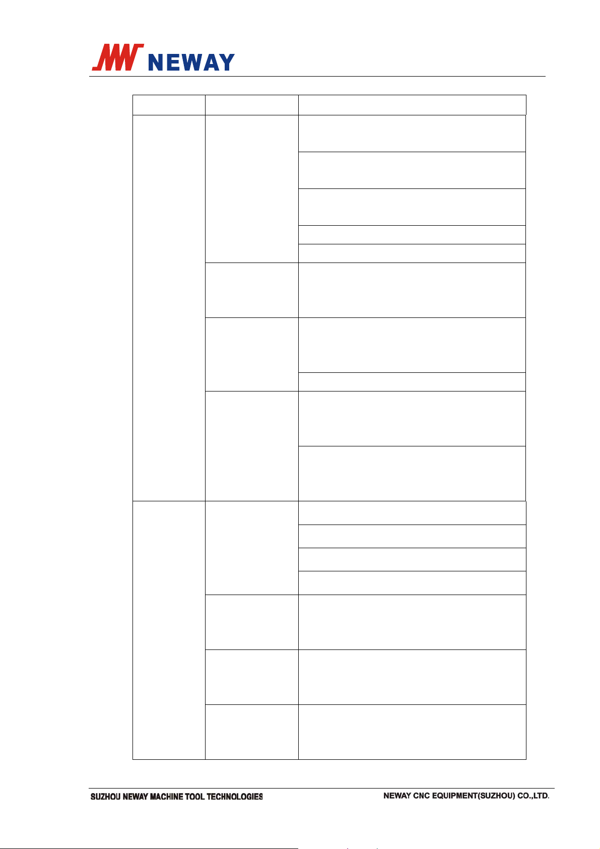
Instruction manual Document No.: VM50-9302E
7.2 Common failures of tool magazine and manipulator
Item Failures
Tool magazine
does not rotate
Tool magazine
Tool
magazine
failure
cannot turn to the
right position
Tool magazine
cannot turn to the
right position
Reasons
Coupling connecting motor shaft and worm
shaft becomes loosened.
Frequency converter fails. Check if the input
and output voltage is normal.
No control output of PLC. The relay in the
interface board is probably ineffective.
Mechanical connection is too tight.
Voltage of electric network is too low.
Motor rotation failure, error in transmission
mechanism.
Adjusting screw in the tool pocket is loosened
or spring is so loosened that the clamping
force is insufficient.
Tool overweight
Manipulator
failure
Tool pocket is
not in right
position when it
goes up and
down
Tool is not
clamped and
usually drops
Tool can’t be
unclamped when
clamped
Tool drops during
tool change
Fork position is incorrect resulting from
inappropriate adjustment and installation or
excessive machining error
Feedback signal is wrong resulting from the
incorrect installation of limit switch or
inappropriate adjustment.
Jaw spring force tool small
Nut loose
Tool overweight
Lock not function
Jaw spring is too tight and jaw can’t draw
back. Loose the nut and the maximum load
shouldn’t exceed the rated value.
Spindle not back to tool change point or tool
change point shifts. It’s necessary to reset the
process
Page 67 Total 72
tool change point.
Tool clamping or unclamping begins even
though manipulator not seize the tool
correctly.
Page 73
Instruction manual Document No.: VM50-9302E
A
A
7.3 Common failures and trouble shooting of main drive system
No. Failures Reasons Trouble shooting
1 Spindle heating Bearing is broken Replace it
The transmission belt
connecting to motor and
Spindle stops
2
during heavy
cutting
3 Tool not clamp
Tool is not
4
unclamped
after clamped
Spindle head
5
too noisy
7.4 Trouble and trouble shooting of cooling system
spindle is over-loosened.
There is oil on the surface of
transmission belt
Transmission belt is ineffective
after a long time utilization
Spring gripper is broken Replace it
Belleville spring is invalid Replace it
Rivet in the tool holder is
over-long
The pressure of cylinder and
stroke are insufficient.
Transmission belt is loosened
or broken
Tension the
transmission belt
Wipe up after clearing
away the oil with
gasoline
Replace it
Replace it
Adjust the pressure
and the position of
travel switch
Adjust or replace the
transmission belt
Inadequate
coolant flow
No coolant out
Pump does not
work
Failure Reason Trouble shooting
1、Water level too low
2、Filter mesh dirty
3、There is air in the pump
1、 Water level too low
2、 Filter dirty Stop machine, clean tank and filter
3、 Pump disorder Fix or change pump
1、 Pump blocked Clean tank and pump
2、 Electric failure Check electric cables
3、 Pump failure Fix or change pump
dd coolant
stop machine, clean tank and filter
mesh
fill up coolant and release air, close
valve
dd coolant
Page 68 Total 72
Page 74
Instruction manual Document No.: VM50-9302E
7.5 Trouble and trouble shooting of pneumatic system
Item Trouble Reasons Trouble shooting
Low pressure Increase air pressure
leakage Replace all leaking connectors
1 Air pressure alarm
2 Solenoid failure
adjusting
3
Relieve valve failure
Throttle valve no
4
flow
Pressure switch
Replace air switch
failure
Alarm set to high adjusting Lower the alarm setting
Bad connection Correct Solenoid connection
Low voltage Connect to correct voltage
Bad connection reconnect
Seal leakage Replace seals
Foreign matter block clean foreign matters
Spring failure Replace spring
Wrong inlet/outlet Reconnect pipes
Spring failure Replace spring
Foreign matter block Clean foreign matters
Seal leakage Replace seals
Relieve valve shut Open the valve
Wrong inlet/outlet Reconnect pipes
Throttle valve failure Replace the valve
Low pressure Increase air pressure
5 No air curtain
6 No air cooling
Tool change
7
cylinder failure
8 No through air blow
Bad connection reconnect
Relieve valve failure Repair relieve valve
Low pressure Increase pressure
Valve off Valve on
Solenoid failure Repair solenoid
Low air pressure Increase air pressure
Solenoid failure Repair solenoid
Low air pressure Increase pressure
Bad connection reconnect
Solenoid failure Repair solenoid
Throttle valve failure Repair throttle
Relieve valve failure Repair relieve valve
Page 69 Total 72
Page 75
Instruction manual Document No.: VM50-9302E
Low air pressure Increase pressure
Bad connection reconnect
9 No ATC action
No air refill after
10
ATC
7.6 Trouble and trouble shooting of ZF retarders
Problems Reasons Trouble shooting
Noise
Noise When switching from
Noise Motor shaft too long,
Gearbox leaks Seal failure Replace seals, send retarder to ZF if
Speed sensor loose;
Sensor dirty;
high gear to low gear
bearing failure
Solenoid failure Repair solenoid
Pneumatic Cylinder
failure
Air tank failure Replace air failure
Repair pneumatic cylinder
Check sensor-motor circuit
Clean/replace speed sensor
Adjust speed control
Try several time more
Check bearing, replace when necessary
necessary
air hole leaks Oil dirty, too much oil Replace oil, check oil level
Speed switching
failure
Gears do not
engage
High temperature Excess or inadequate oil
Internal parts burnt
Switching pin loose
parts failure
PLC wrong assembly
Sleeve teeth worn out
Stopper failure Send gearbox back to ZF
drainage end upwards,
Drainage pipe dia. too
small, overflow hole too
high
Sun gear bearings worn
out;
Bad assembly, foreign
matter;
Inadequate oil flow;
check if lubricant gets in the switching
organ. Clean pin and clamp the connector
tightly.
PLC eccentricity too much, speed too high
adjusting
Send gearbox back to ZF
OEM parts failure, oil
cooler failure.
Page 70 Total 72
Page 76

Instruction manual Document No.: VM50-9302E
7.7 Replacement and wear parts list
Name Wear parts
Cylinder Oil seal, O-ring
Full-enclosed protective Brush, Guide rail, Idler wheel, Scraping board
The shield of guide rail Three axes’ shield of guide rail
Pneumatic pipeline
Lubrication Lubricant pump, Quantitive grease injector
Hydraulic pressure
station
Cooling and chip
removal
Electrical parts Proximity, Fuse
Air treatment unit, Solenoid valve, Reducing valve,
throttle valve, Cable carrier
Filter element, Electromagnetic coil
Vertical pump, Level gauge, Spiral type
Page 71 Total 72
Page 77

Instruction manual Document No.: VM50-9302E
8 Recirculation and environmental protection
Material Treatment
Metal All the metal materials of the machine tool are recyclable.
Plastic
Glass It can be centralized treated by the glass suppliers after it is dismantled.
Other
materials
The
scrapped or
damaged
parts
9 Declaration and others
9.1 Declaration
in this Instruction Manual may be different from the machine tool delivered. Please note
that our company has the final explanation right to this manual.
9.2 Address and contacts
Address: No. 69 Xunyangjiang Road, Suzhou, China
All the plastic materials of the machine tool can be recirculated through
melting, granulating and smashing.
The electrical and other materials can be disposed by the approved
organization.
The scrapped or damaged parts can’t be abandoned at will. For the
unrecyclable parts, hand them over to the approved organization.
Please notice that due to the continuous improvement of products, the description
Company: Neway CNC Equipment (Suzhou) Co., Ltd.
Post code: 215153
Service hotline: 0512-6607-6668
Sale hotline: 0512-6607-0166
Fax: 0512-6607-1116
E-mail: [email protected]
Website: http://www.newaycnc.com
9.3 Illustration of machine fixation
Remark: This manual is an integrated version for multiple models, therefore the fixed
condition of each machine may be different. Please refer to the final product
Page 72 Total 72
Page 78
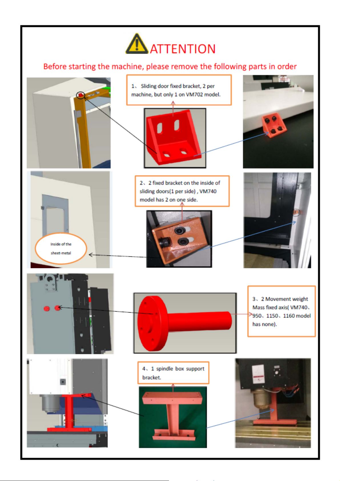
Page 79
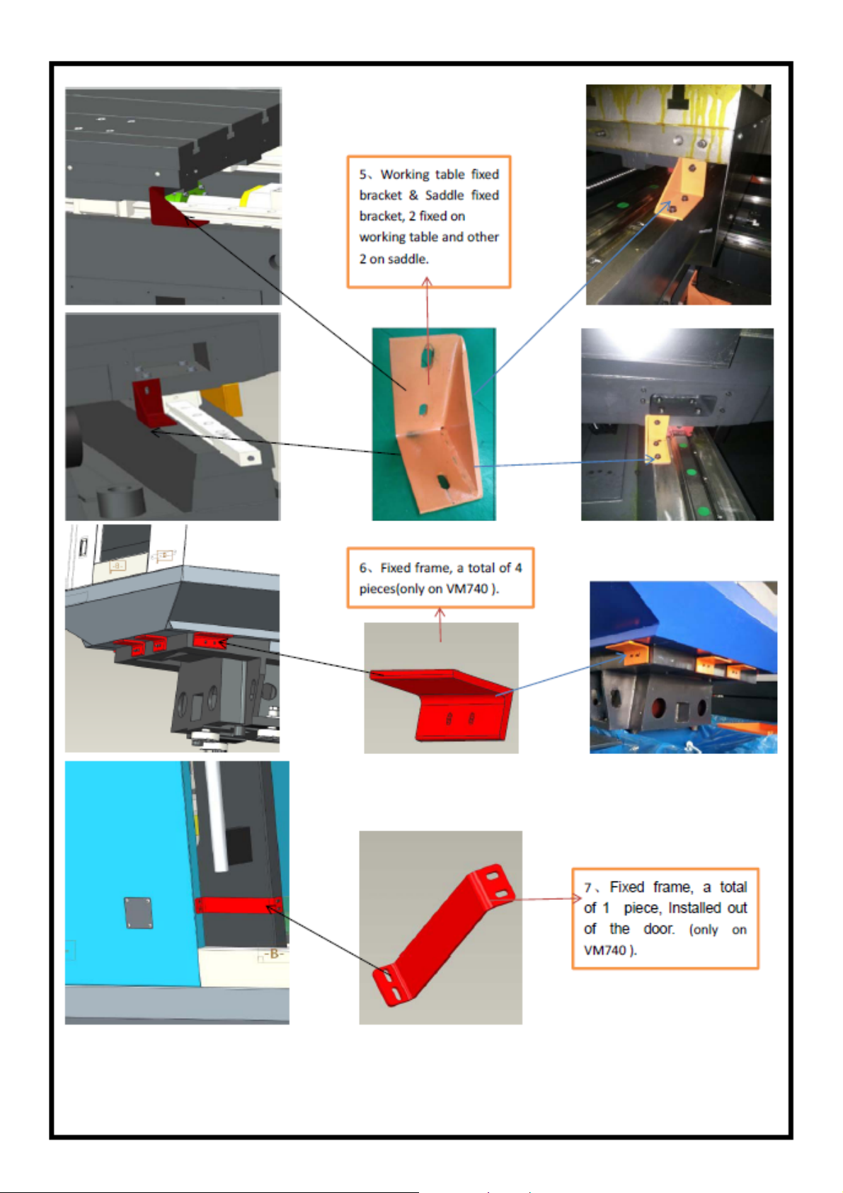
Page 80
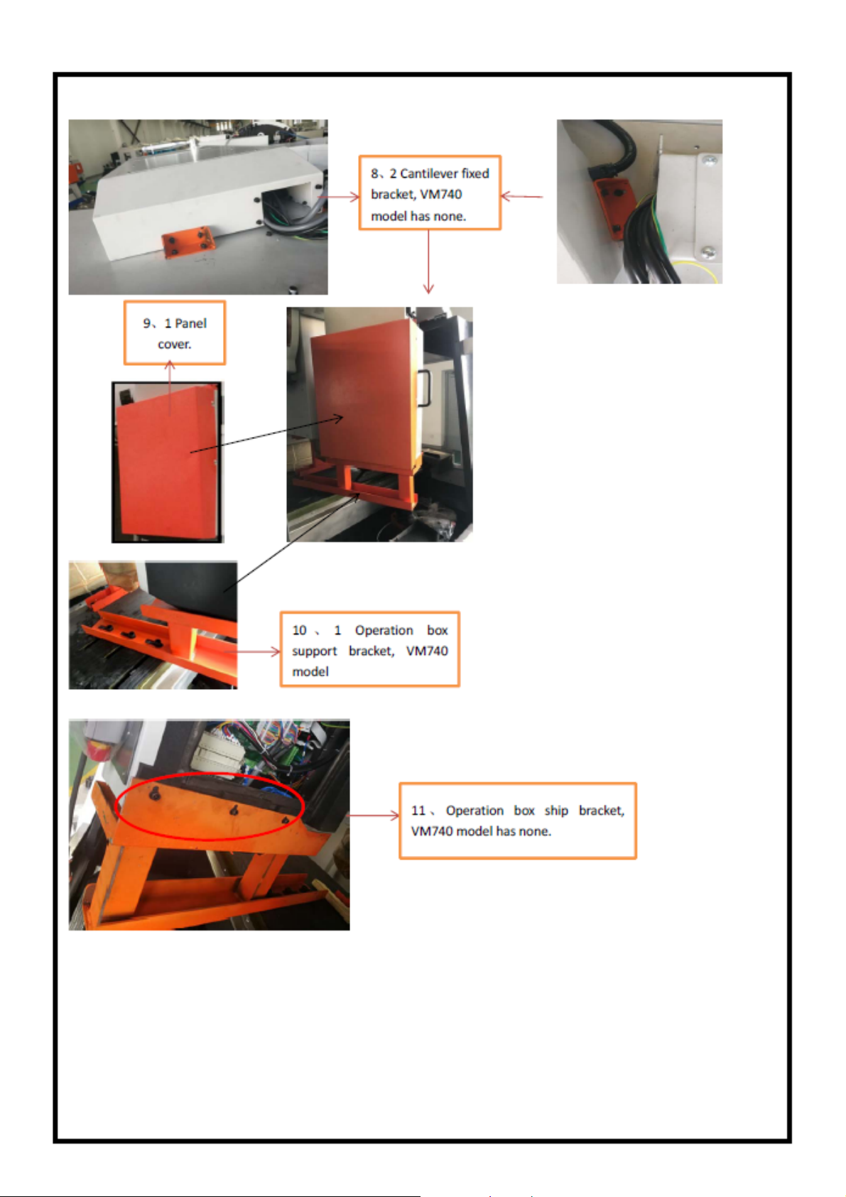
Page 81
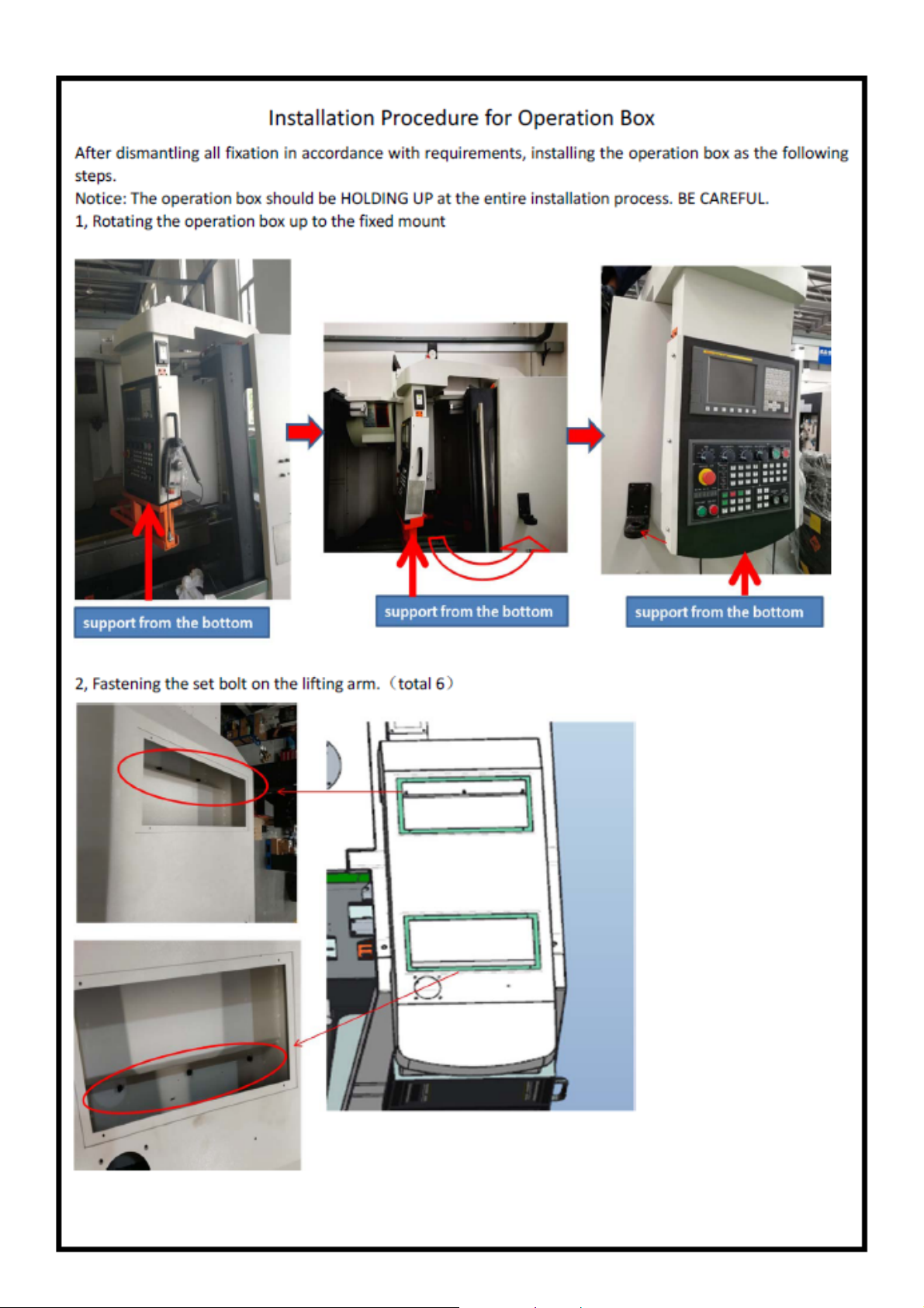
Page 82
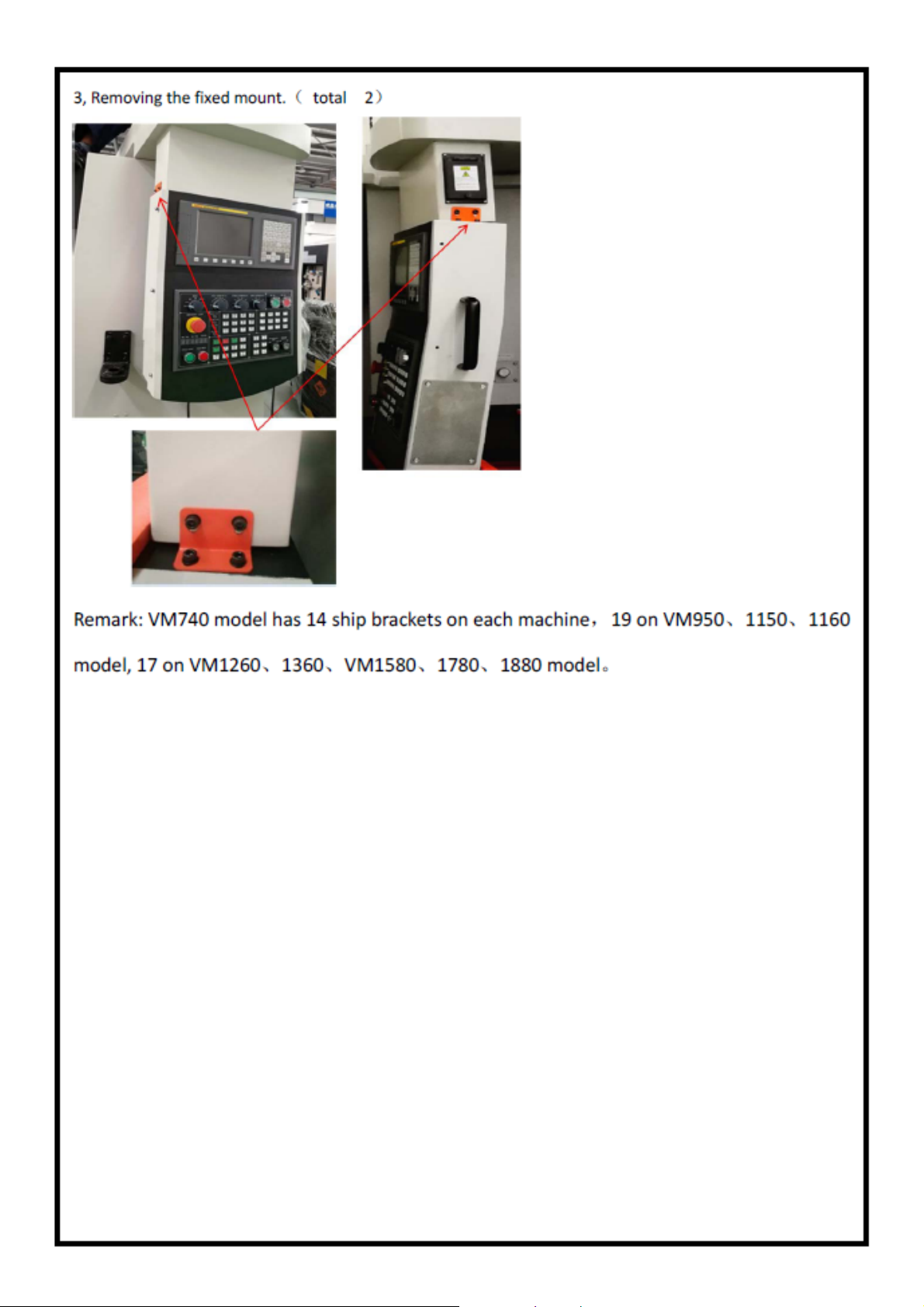
 Loading...