

Page 1
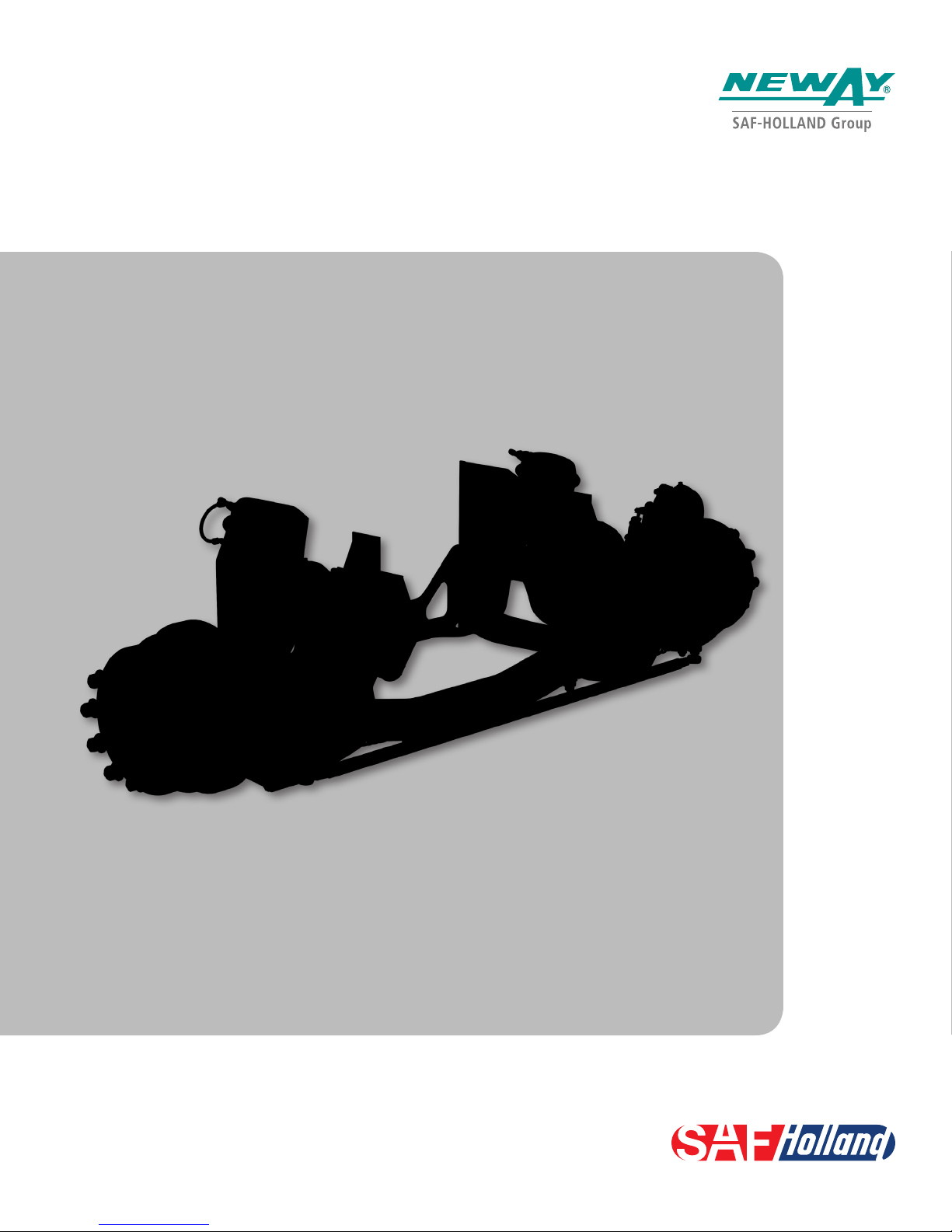
LSZ13 Repair Manual
Lift Mechanism and SuperChamber™
XL-PS20059RM-en-US Rev A
Page 2
Contents
Contents Page
Introduction ......................................................................... 2
Warranty .............................................................................. 2
Notes, Cautions, and Warnings ............................................. 2
Section 1 – Safety Instructions ............................................. 3
SRK Kits ............................................................................... 4
Introduction
This manual provides the necessary information for the
maintenance, inspection, and safe operation of the NEWAY®
LSZ Series Auxiliary Air Suspension.
NOTE: To assist with installation, customer inspection
drawing LSZ13_TAB_CI or LSZ20_TAB_CI is
required and is included in the literature kit.
Read this manual before using or servicing this product and
keep it in a safe location for future reference. Updates to this
manual, which are published as necessary, are available on
the internet at www.safholland.us.
Contents Page
Section 2 – Lift Mechanism .................................................. 5
Section 3 – SuperChamber Replacement .............................. 6
Section 4 – Torque Specifications ......................................... 8
Section 5 – Lubrication Specifications .................................. 8
Notes, Cautions, and Warnings
Before starting any work on the unit, read and understand all
the safety procedures presented in this manual. This manual
contains the terms “NOTE”, “IMPORTANT”, “CAUTION”, and
“WARNING” followed by important product information. These
terms are defined as follows:
NOTE: Includes additional information to enable accurate
and easy performance of procedures.
IMPORTANT: Includes additional information that
if NOT followed could lead to hindered
product performance.
When replacement parts are required, SAF-HOLLAND® highly
recommends the use of only SAF-HOLLAND Original Parts.
A list of technical support locations that supply SAF-HOLLAND
Original Parts and an Aftermarket Parts Catalog are available
on the internet at www.safholland.us or contact Customer
Service at 888-396-6501.
Warranty
Refer to the complete warranty for the country in which
the product will be used. A copy of the written warranty
is included with the product or available on the internet
at www.safholland.com.
Used without the safety alert symbol,
indicates a potentially hazardous
situation which, if not avoided, could
result in property damage.
Indicates a potentially hazardous
situation which, if not avoided, could
result in minor or moderate injury.
Indicates a potentially hazardous
situation which, if not avoided, could
result in death or serious injury.
2
XL-PS20059RM-en-US Rev A · 2017-02-27 · Amendments and Errors Reserved © SAF-HOLLAND, Inc., SAF-HOLLAND, HOLLAND, NEWAY, SAF, and logos are trademarks of
SAF-HOLLAND S.A., SAF-HOLLAND GmbH, and SAF-HOLLAND, Inc.
Page 3
1. Safety Instructions
General Safety
General and Servicing Safety Instructions
Read and observe all Warning and Caution hazard alert
messages. The alerts provide information that can help prevent
serious personal injury, damage to components, or both.
Failure to follow the instructions and safety
precautions in this manual could result in
improper servicing or operation leading
to component failure which if not avoided
could result in death or serious injury.
All installations should be performed by a properly
technician using proper/special tools, and safe procedures.
NOTE: In the United States, workshop safety requirements
are defined by federal and/or state Occupational
Safety and Health Act (OSHA). Equivalent laws could
exist in other countries. This manual is written based
on the assumption that OSHA or other applicable
employee safety regulations are followed by the
location where work is performed.
Properly support and secure the vehicle from unexpected
movement when servicing the unit.
Failure to properly support and secure the
vehicle and axles prior to commencing work
could create a crush hazard which, if not
avoided, could result in death or serious injury.
Service both roadside and curbside of an axle. Worn parts
should be replaced in sets. Key components on each axle’s
braking system, such as friction material, rotors and drums
will normally wear over time.
Follow all manufacturer’s instructions on spring pressure
and air pressure controls.
Failure to follow manufacturer’s instructions
regarding spring pressure or air pressure
control could allow unexpected release of
energy which, if not avoided, could result
in death or serious injury.
The wheel contact surfaces between the wheel and hub/drum
MUST NOT be additionally painted.
IMPORTANT: The wheel contact surfaces MUST be clean,
smooth and free from grease.
Failure to keep wheel and hub contact surfaces
clean and clear of foreign material could
allow wheel/hub separations which, if not
avoided, could result in death or serious injury.
Only the wheel and tire sizes approved by SAF-HOLLAND
can be used.
Tire clearance between tires and the suspension MUST be
regularly monitored and maintained.
Failure to maintain tire clearance between
tires and the nearest point of contact on
the suspension or vehicle could cause
fire or loss of vehicle control which, if not
avoided, could result in death or serious injury.
trained
Operational and Road Safety Instructions
Before operating vehicle, ensure that the maximum permissible
axle load is NOT exceeded and that the load is distributed
equally and uniformly and in accordance with state and
federal bridge laws.
Make sure that the brakes are NOT overheated from
continuous operation.
Failure to minimize the use of brakes during
overheating conditions could result in
deterioration of brake efficiency which, if not
avoided could result in death or serious injury.
Observe the operating recommendation of the truck
manufacturer for off-road operation of the installed axles.
IMPORTANT:
IMPORTANT:
Follow the recommended routine maintenance and inspections
described in this manual. These procedures are designed so
that optimum performance and operational safety are achieved.
The suspension springs should ALWAYS be operated with
a static operating pressure between 20 psi (1.38 bar)
and 107 psi (7.38 bar).
In the event of suspension air pressure loss, quickly reduce
speed as safely as possible and remove the vehicle from
traffic. If unable to remove vehicle from traffic, follow DOT
safety requirements regarding emergency situations.
Contact a qualified towing and/or service company to assist
in repairing the vehicle or to move it to a qualified repair facility.
DO NOT operate the vehicle in the absence of suspension
air pressure; however in the event of an air system failure
while in service, an internal rubber bumper built into the
air spring will make it possible to temporarily operate the
vehicle at reduced speed determined by road conditions.
The suspension MUST be lifted when the vehicle is moving
in reverse.
The definition of OFF-ROAD means driving
on non-asphalt/non-concrete routes, e.g.
gravel roads, agricultural and forestry tracks,
on construction sites and in gravel pits.
Off-road operation of axles beyond
the approved application design could
result in damage and impair suspension
system performance.
Failure to operate the air springs with a
proper static operating pressure could
cause premature component failure and
loss of vehicle control which, if not avoided,
could result in death or serious injury.
Operating the vehicle without proper air
pressure can cause tire failure, fire, or loss of
vehicle control which, if not avoided could
result in death or serious injury.
Failure to lift axle when in reverse could
result in tire or axle damage.
XL-PS20059RM-en-US Rev A · 2017-02-27 · Amendments and Errors Reserved © SAF-HOLLAND, Inc., SAF-HOLLAND, HOLLAND, NEWAY, SAF, and logos are trademarks of
SAF-HOLLAND S.A., SAF-HOLLAND GmbH, and SAF-HOLLAND, Inc.
3
Page 4
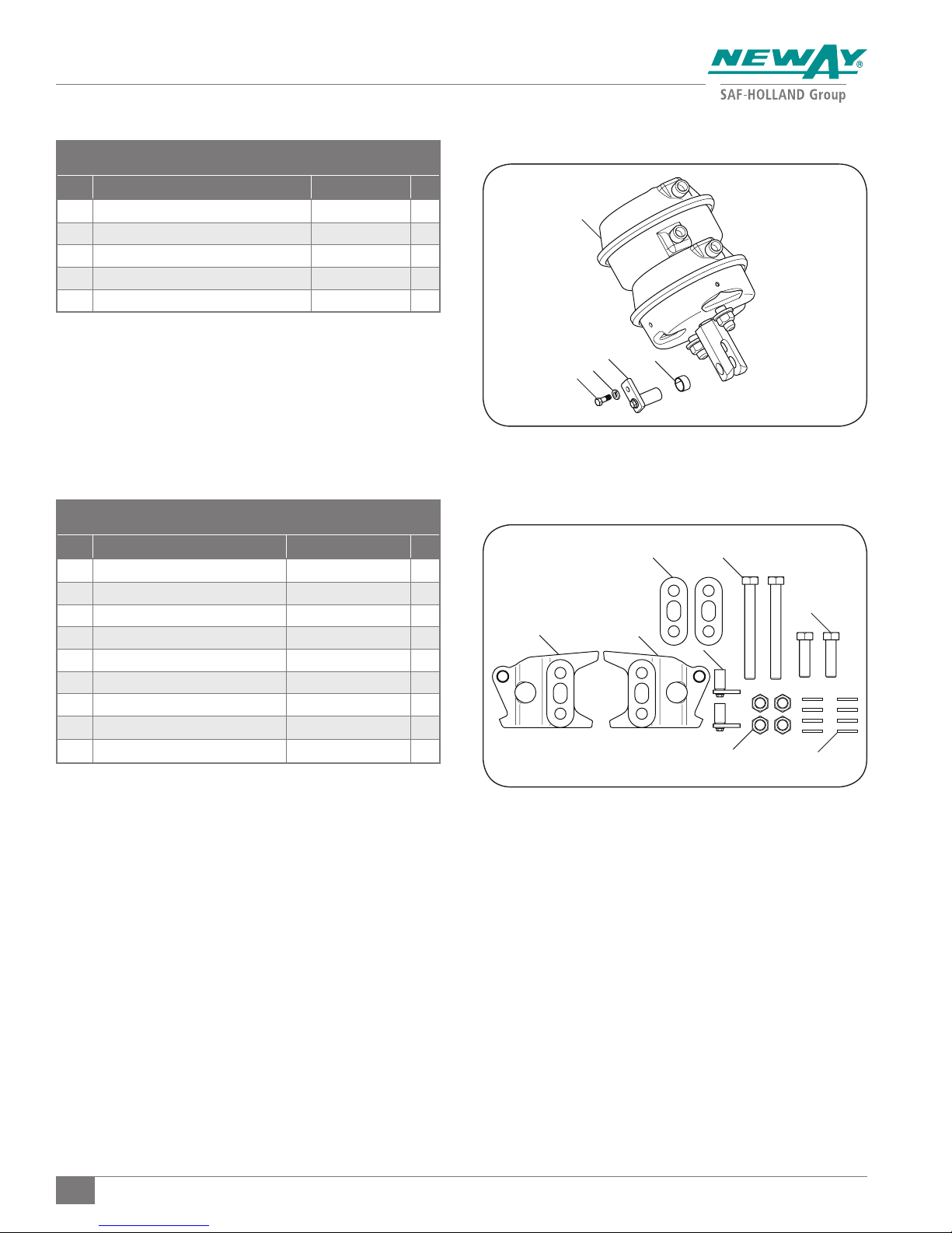
SRK Kits
SRK 48100570: SUPERCHAMBER KIT LSZ
ITEM DESCRIPTION PART NUMBER QTY.
1 SuperChamber Assembly 90550330 1
5 Lock Washer, Extra Duty, Helical Spring 93600043 1
6 Hex Head Cap Screw .31"-18 x 3/4" GR 8 93002459 1
8 Bearing 90045716 1
9 Clevis Pin Assembly 90501539 1
SRK 48100609: HARDWARE KIT, LIFT MECHANISM, LSZ13
ITEM DESCRIPTION PART NUMBER QTY.
1 Clevis Pin Assembly 90501539 2
2 Lower Lift Bracket Assembly - LH 90550326 1
3 Lower Lift Bracket Assembly - RH 90550327 1
4 Repair Manual (Not Shown) XL-PS20059RM-en-US 1
5 Bolt, 3/4"- 10 x 2 3/4" GR 8 93003581 2
6 Bolt, 3/4"- 10 x 7" GR 8 93003683 2
7 Washer, Flat 3/4" 93600156 8
8 Nut, Hex, Lock 3/4"- 10 GR C 93400494 4
9 Shim, Lower Lift Bracket 90036306 2
48100570
48100609
2
1
8
5
6
9
69
5
3
1
8
7
4
XL-PS20059RM-en-US Rev A · 2017-02-27 · Amendments and Errors Reserved © SAF-HOLLAND, Inc., SAF-HOLLAND, HOLLAND, NEWAY, SAF, and logos are trademarks of
SAF-HOLLAND S.A., SAF-HOLLAND GmbH, and SAF-HOLLAND, Inc.
Page 5
Lift Mechanism
2. Lift Mechanism
Required Tools:
1-1/8" Open End Wrench
and Socket
1/2" Wrench or Socket
1. With the vehicle unloaded and/or trailer disconnected on
a level surface, set parking brakes and chock drive tires
to prevent the vehicle from rolling forward or backward.
Failure to properly secure the vehicle prior
to commencing work could create a crush
hazard which, if not avoided, could result
in death or serious injury.
2. Put suspension in the in-service position with no air
pressure in the suspension air springs. Exhaust the air
pressure using the air pressure regulator or control valve.
Failure to exhaust the suspension air
and chock the tires prior to beginning
maintenance could allow vehicle
movement which, if not avoided, could
result in death or serious injury.
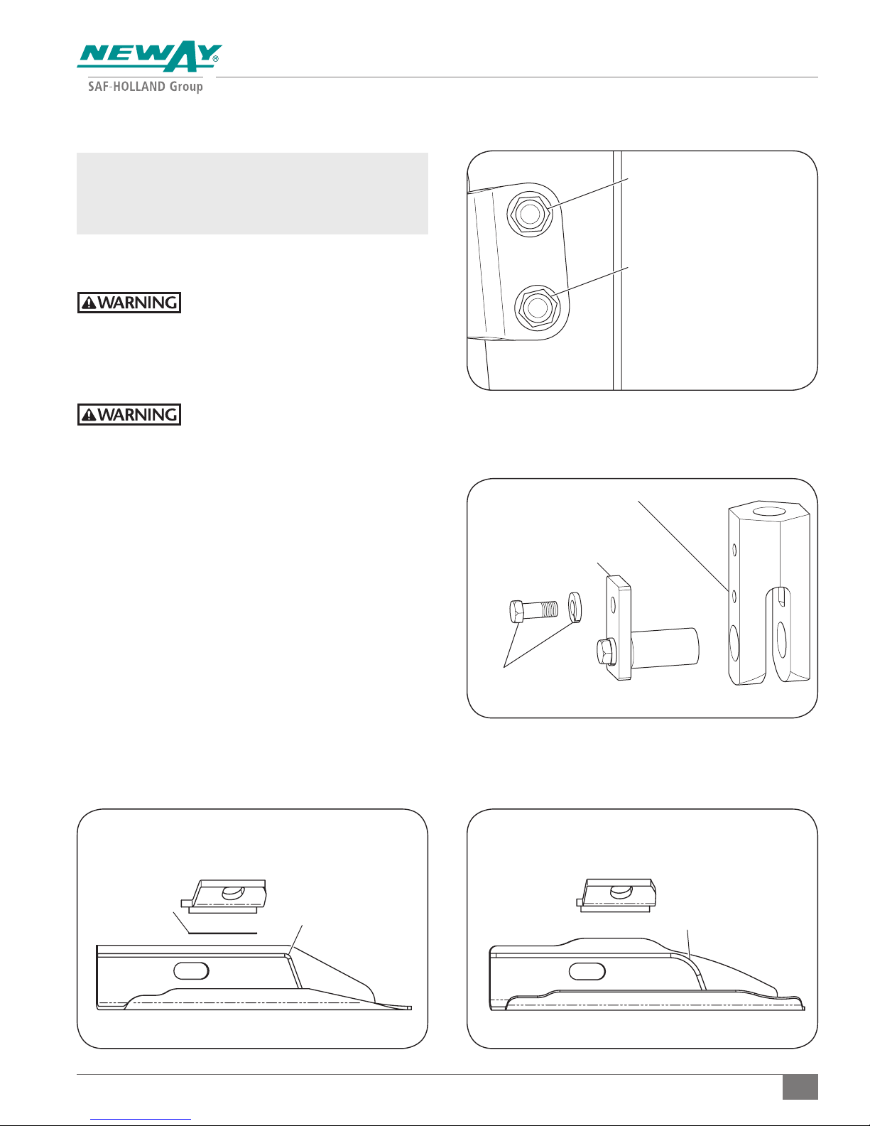
3. Using a wrench and socket, remove and discard the
upper pivot bolt, locknut and flat washers (Figure 1).
4. Using a 1-1/8" wrench and socket, remove and discard the
lower 3/4" lift bracket locknut and flat washers (Figure 2).
5. Use a small pry bar to pry the clevis downward to
overcome the return spring force. This will allow the
removal of the lower lift bracket 3/4" bolt and washer.
Discard the 3/4" washer and lower lift bracket 3/4" bolt.
6. Using a 1/2" wrench or socket to remove and retain the
upper 5/16" bolt and lock washer from the clevis. Remove
and discard the clevis pin assembly and lower lift bracket.
7. Install the new upper pivot bolt and flat washer.
8. When installing the new lower lift bracket you first have
to determine which generation of frame bracket that is
installed (Figure 3 and 4). Once determined if the shim
is needed, install the new lower lift bracket onto the new
upper pivot bolt with or without the shim. Install the flat
washer with a new locknut and hand tighten the locknut.
Small Pry Bar
250 ft-lb Torque Wrench
Figure 1
UPPER PIVOT LOCKNUT
LOWER 3/4" LIFT
BRACKET LOCKNUT
Figure 2
TAPPED, OUTSIDE CLEVIS EAR
CLEVIS PIN ASSEMBLY
CLEVIS PIN ASSEMBLY
RETAINING 5/16-18 x 3/4"
BOLT AND LOCK WASHER
INSTALL SHIM
XL-PS20059RM-en-US Rev A · 2017-02-27 · Amendments and Errors Reserved © SAF-HOLLAND, Inc., SAF-HOLLAND, HOLLAND, NEWAY, SAF, and logos are trademarks of
SAF-HOLLAND S.A., SAF-HOLLAND GmbH, and SAF-HOLLAND, Inc.
SMALL RADIUS
1/4" PLATE
Figure 4Figure 3
2ND GENERATION1ST GENERATION
LARGE RADIUS
5/16" PLATE
5
Page 6
SuperChamber Replacement
9. Use a small pry bar to pry the clevis downward to
overcome the return spring force Install the new clevis
pin assembly, 5/16" bolt and lock washer. Torque
according to specifications in Table 1.
10. Use a small pry bar to pry the clevis downward to
overcome the chamber return spring force. This will allow
the installation of the new lower 3/4" bolt, washers and
locknut. Make sure the lower lift bracket alignment legs
contact the front frame bracket flange (Figure 5). Torque
all fasteners according to specifications in Table 1.
11. Repeat steps 3 through 10 on the opposite side.
12. Remove the wheel chocks from the drive tires.
3. SuperChamber Replacement
Required Tools:
1-1/8" Open End Wrench
1-1/8" Socket
3/4" Open End Wrench
15/16" Wrench
Torque Wrench Capable of 250 ft.-lbs.
NOTE:
It is recommended that the lift mechanism is
replaced at the same time as the SuperChamber.
1. With the vehicle unloaded and/or trailer disconnected on
a level surface, set parking brakes and chock drive tires
to prevent the vehicle from rolling forward or backward.
Failure to properly secure the vehicle prior
to commencing work could create a crush
hazard which, if not avoided, could result
in death or serious injury.
2. Put suspension in the in-service position. Exhaust air
pressure in the suspension air springs. Remove the air
pressure using the air pressure regulator or control valve.
Failure to exhaust the suspension air
and chock the tires prior to beginning
maintenance could allow vehicle
movement which, if not avoided, could
result in death or serious injury.
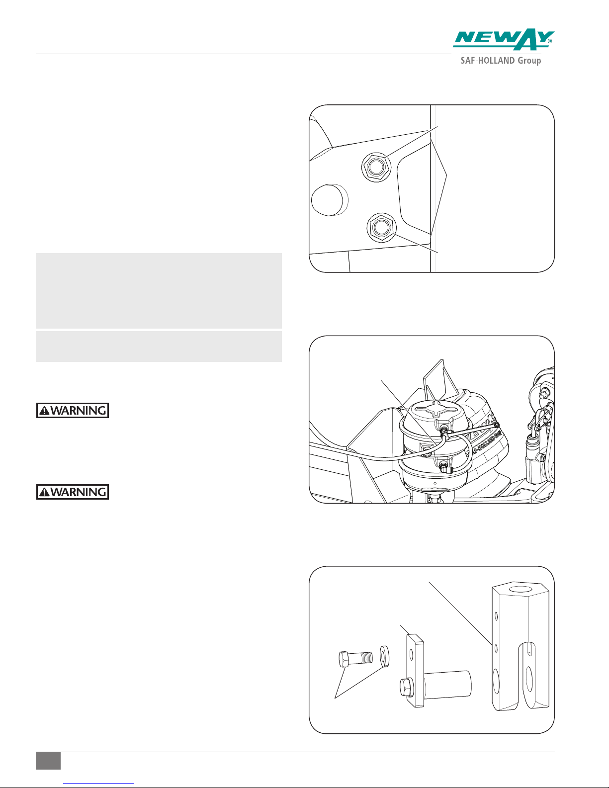
3. Using a 3/8" wrench, depress the release button on the
SuperChamber push to connect fittings to allow the
removal of the 6" jumper tube. Retain the jumper tube.
4. Using a 3/8" wrench, depress the release button on
the SuperChamber push to connect fitting to allow the
removal of the 3/8" SuperChamber air supply tubing
(Figure 6)
.
5. Using a 3/4" open end wrench, remove and retain both
fittings from the installed SuperChamber.
6. Using a 1/2" wrench or socket remove the upper 5/16"
bolt and lock washer from the SuperChamber clevis. Use
a small pry bar to pry the clevis downward to overcome
the return spring force. This will allow the removal of the
clevis pin assembly
(Figure 7)
7. Using a 15/16" wrench, remove and discard both 5/8"
nuts and lock washers retaining the SuperChamber to the
chamber bracket.
Small Pry Bar
1/2" Socket or Wrench
3/8" Open End Wrench
.
Figure 5
UPPER PIVOT LOCKNUT
KEEP ALIGNMENT LEGS
TIGHT TO THE FRONT OF
THE FRAME BRACKET
LOWER 3/4" LIFT
BRACKET LOCKNUT
Figure 6
AIR SUPPLY TUBING
Figure 7
TAPPED, OUTSIDE CLEVIS EAR
CLEVIS PIN ASSEMBLY
CLEVIS PIN ASSEMBLY
RETAINING 5/16-18 x 3/4"
BOLT AND LOCK WASHER
6
XL-PS20059RM-en-US Rev A · 2017-02-27 · Amendments and Errors Reserved © SAF-HOLLAND, Inc., SAF-HOLLAND, HOLLAND, NEWAY, SAF, and logos are trademarks of
SAF-HOLLAND S.A., SAF-HOLLAND GmbH, and SAF-HOLLAND, Inc.
Page 7
SuperChamber Replacement
8. Remove the SuperChamber.
9. Install the new SuperChamber using two (2) new
5/8" nuts and lock washers onto the studs of the
new SuperChamber. Torque both nuts according to
specifications in
Table 1
.
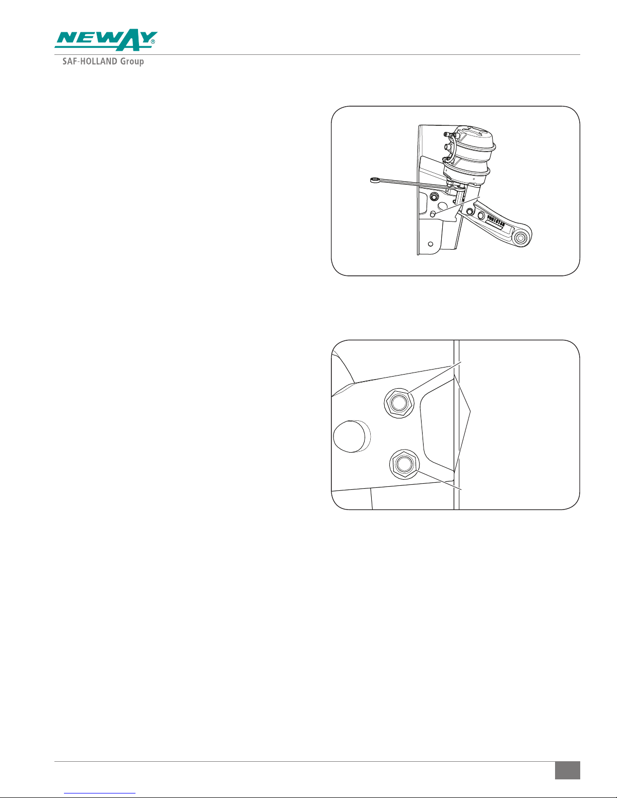
10. Use a small pry bar or open end wrench to pry the clevis
downward to overcome the return spring
(Figure 8)
.
This will allow the installation of the clevis pin assembly.
11. Install the 5/16" bolt and lock washer, into the upper
position of the clevis
according to specifications in
(Figure 7)
Table 1
. Torque the bolt
.
12. Using a 3/4" open end wrench, re-install the install
both fittings into the top and bottom port on the
SuperChamber. Install the air supply tubing into the Tee
and jumper from the Tee to elbow.
13. Install the upper pivot bolt and flat washer.
14. Install the lower lift bracket onto the upper pivot bolt.
Install the 3/4" flat washer and locknut and hand tighten
the locknut.
15. Rotate the lift bracket to allow the installation of the new
clevis pin assembly. Install the new 5/16" bolt and lock
washer. Torque According to specifications in Section 4.
16. Use a small pry bar or open end wrench to pry the clevis
downward to overcome the return spring (Figure 8). This
will allow the installation of the lower 3/4" bolt and 3/4"
flat washer into the lower hole of the lower lift bracket.
Install the nut and washer on the lower bolt on the lower
lift bracket. Position the lower lift bracket so the alignment
legs contact the frame bracket edge (Figure 9). Torque
both the upper pivot and lower lift bracket locknuts to
specifications in
Table 1
.
17. Build air pressure on the truck to a minimum of 100 psi.
Lift the axle and check the fittings for leaks using soapy
suds. Tighten fittings if leaks found at the threaded joints.
18. Remove the wheel chocks from the drive tires.
Figure 8
3/4" LIFT BRACKET BOLT
Figure 9
UPPER PIVOT LOCKNUT
KEEP ALIGNMENT LEGS
TIGHT TO THE FRONT OF
THE FRAME BRACKET
LOWER 3/4" LIFT
BRACKET LOCKNUT
XL-PS20059RM-en-US Rev A · 2017-02-27 · Amendments and Errors Reserved © SAF-HOLLAND, Inc., SAF-HOLLAND, HOLLAND, NEWAY, SAF, and logos are trademarks of
SAF-HOLLAND S.A., SAF-HOLLAND GmbH, and SAF-HOLLAND, Inc.
7
Page 8
Torque Specifications
4. Torque Specifications
NOTE: Torque specifications listed in this section are with clean
lubricated/coated threads, supplied by SAF-HOLLAND.
IMPORTANT: The use of special lubricants with friction
modifiers, such as Anti-Seize or Never-Seez®,
without written approval from SAF-HOLLAND
Engineering, will void warranty and could
lead to over torquing of fasteners or other
component issues.
General Information
The torque specifications listed throughout the manual are
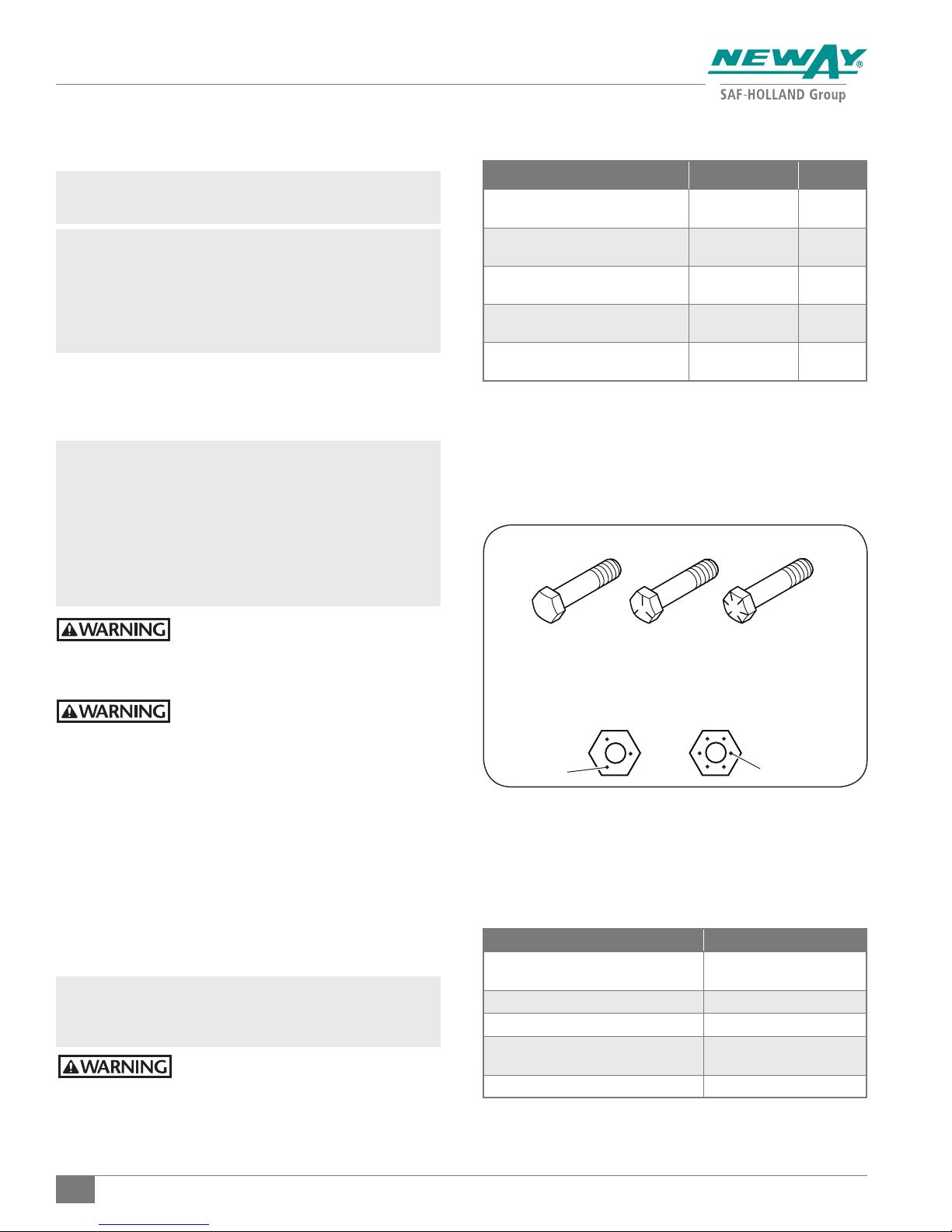
applied to the lock nut and NOT the bolt.
IMPORTANT: Most of the fasteners used in this suspension
are Grade 8 bolts and Grade C lock nuts.
These fasteners have the strength and
hardness properties required for their
particular function. They MUST be replaced
with fasteners of the same grade, size and
form as the original in order to prevent
failure (Figure 10).
Table 1
COMPONENT TORQUE RANGE SIZE
Clevis Pin Assembly
SuperChamber Bracket
SuperChamber and
Service Brake Chamber
Lift Bracket, King Pin Bolt,
Crossmember, and Tie Rod
LSZ13 Pivot Connections
Figure 10
BOLT GRADE MARKINGS
18-24 ft.-lbs.
24-33 N•m 5/16"-18
47-63 ft.-lbs.
64-85 N•m 1/2"-13
133-155 ft.-lbs.
180-210 N•m 5/8"-11
200-250 ft.-lbs.
271-339 N•m 3/4"-10
200-250 ft.-lbs.
271-339 N•m 3/4"-10
Failure to use the proper fasteners when
servicing the suspension could cause
component failure which, if NOT avoided,
could result in death or serious injury.
Failure to properly torque all fasteners
will result in component failure which,
if NOT avoided, could result in death or
serious injury.
All fasteners MUST be re-torqued after the first 100 hours
of service or 5,000 miles (8,000 km).
Refer to vehicle OEM for torque specifications for vehicle
frame fastener hardware.
5. Lubrication Specifications
Lubricate the suspension in accordance with the approved
lubricants (Table 2).
IMPORTANT: Replacement of SAF-HOLLAND supplied
fasteners with non-SAF-HOLLAND could result
in unpredictable performance.
Failure to maintain the LSZ suspension
with SAF-HOLLAND original parts can
result in unpredictable performance
which, if NOT avoided, could result in
death or serious injury.
GRADE 1 OR 2
LOCK NUT GRADE MARKINGS
3 DOTS
GRADE 5 GRADE 8
LOCK NUT
GRADE B
LOCK NUT
GRADE C
6 DOTS
Table 2
GREASE HUB OIL
SAF® Premium Synthetic Grease 50844001
CITGO SynDurance Premium Synthetic 460 Shell Spirax S 75W-90
Mystik JT-6 Hi Temp with Moly Shell Spirax ASX 75W-90
Valvoline Palladium Grease
Chevron Delo Heavy Duty Moly 5% EP Exxon Mobil Delvac 75W-90
Exxon Mobil Mobilube HD Plus
80W-90
Exxon Mobil Mobilube 1 SHC
75W-90
8
XL-PS20059RM-en-US Rev A · 2017-02-27 · Amendments and Errors Reserved © SAF-HOLLAND, Inc., SAF-HOLLAND, HOLLAND, NEWAY, SAF, and logos are trademarks of
SAF-HOLLAND S.A., SAF-HOLLAND GmbH, and SAF-HOLLAND, Inc.
Page 9
Notes
XL-PS20059RM-en-US Rev A · 2017-02-27 · Amendments and Errors Reserved © SAF-HOLLAND, Inc., SAF-HOLLAND, HOLLAND, NEWAY, SAF, and logos are trademarks of
SAF-HOLLAND S.A., SAF-HOLLAND GmbH, and SAF-HOLLAND, Inc.
9
Page 10
Notes
10
XL-PS20059RM-en-US Rev A · 2017-02-27 · Amendments and Errors Reserved © SAF-HOLLAND, Inc., SAF-HOLLAND, HOLLAND, NEWAY, SAF, and logos are trademarks of
SAF-HOLLAND S.A., SAF-HOLLAND GmbH, and SAF-HOLLAND, Inc.
Page 11
Notes
XL-PS20059RM-en-US Rev A · 2017-02-27 · Amendments and Errors Reserved © SAF-HOLLAND, Inc., SAF-HOLLAND, HOLLAND, NEWAY, SAF, and logos are trademarks of
SAF-HOLLAND S.A., SAF-HOLLAND GmbH, and SAF-HOLLAND, Inc.
11
Page 12
From fifth wheel rebuild kits to suspension bushing repair kits,
SAF-HOLLAND Original Parts are the same quality components used
in the original component assembly.
SAF-HOLLAND Original Parts are tested and designed to provide
maximum performance and durability. Will-fits, look-alikes or, worse
yet, counterfeit parts will only limit the performance potential and
could possibly void SAF-HOLLAND’s warranty. Always be sure to spec
SAF-HOLLAND Original Parts when servicing your
SAF-HOLLAND product.
SAF-HOLLAND USA
www.safholland.us
SAF-HOLLAND CANADA
WESTERN CANADA
www.safholland.ca
SAF-HOLLAND MEXICO
www.safholland.com.mx
SAF-HOLLAND INC.
1950 Industrial Blvd., Muskegon, MI 49442
www.safholland.com
888.396.6501
·
519.537.3494
·
604.574.7491
·
55.55.5362.8743
·
Fax 800.356.3929
·
Fax 800.565.7753
·
Fax 604.574.0244
·
Fax 52.55.5362.8743
·
XL-PS20059RM-en-US Rev A · 2017-02-27 · Amendments and Errors Reserved © SAF-HOLLAND, Inc., SAF-HOLLAND, HOLLAND, NEWAY, SAF, and logos are trademarks of SAF-HOLLAND S.A., SAF-HOLLAND GmbH, and SAF-HOLLAND, Inc.
 Loading...