

Page 1

RT2000 Instructions
1.4 Advanced Features
Latest generation IGBT technology.
TheRT2000 uses the latest generation IGBT power
modules, these have lower running losses thereby
increasing the duty cycle of the machine and
increasing reliability.
Initial soft-start operation.
The output power is inhibited until the reservoir
capacitors have charged up to full value. This
reduces the stress on the internal components at
the crucial switch on period.
Powerful electronic arc ignition
The advanced arc ignition system contains no
moving parts or spark gap providing long term
reliability even in humid conditions.
This Product meets the conformity
requirements for CE marking
1.3 Technical Data
Rated supply voltage 230v 10 single phase
115/230v 10% single phase
Power consumption 5.1 KVA
Supply current (230v) 21A
Supply current (115v) 42A
Mains input fuse (230v) 20A slow blow or type C MCB.
Mains input fuse (115v) 40A slow blow or type C MCB
Mains cable (230v) 3 x 2.5mm2 flexible cable
Mains cable (115/DV) 3 x 6mm2 flexible cable
Degree of protection IP 2I
Insulation class F
Weight 17.5kg
Overall dimensions 325H 152W 415L
(excluding handle)
Current range TIG 5 to 200A infinitely variable
Current range MMA 5 to 150A infinitely variable
Electrode size 1.6 - 4mm
Duty cycle 100% @ 25º
Before using the RT2000 Inverter based welding
machine, all personnel authorised to use, repair or
service it should read this manual carefully,
especially the section on safety.
Further information is available in publication
HSG118 'Electric safety in arc welding', which
may be obtained from the Health & Safety
Executive.
Please contact your distributor should you not
understand any of the information within this
document.
1.1 Description
The RT2000 is a 200 amp (150 amp on MMA)
constant current TIG welding machine based on
IGBT technology. The inverter drive circuitry
operates above the audio frequency spectrum
making the RT2000 virtually silent in operation.
The high operational frequency also means that the
RT2000 is able to respond quickly to changing arc
dynamics, making for a very smooth stable arc.
As well as TIG welding the RT2000 is capable of
MMA welding with all types of electrodes within the
current rating of the machine, normally up to 4mm.
The RT2000 is available in two versions, a 230v
only, and a 115/230v auto switching Dual Voltage
version.
1.2 Content
1 Description and Technical data
2 General precautions
3 Installation
4 Operation and Use
5 Fault finding and maintenance
6 Parts breakdown
7 Circuit diagram
8 Distributor network and
guarantee
Issue2 January 2004
Important Information
RT2000 Instructions for use Page 1
16/05/2014
Page 2

2 General precautions
2.1 Fire and Explosions
Pay attention to fire and safety regulations in
force at the welding site.
Remove all flammable or combustible materials
from the welding area and the immediate
vicinity.
Suitable fire fighting equipment must always be
present where welding is carried out.
Be aware that a fire risk is present for a
considerable time after welding operations have
ceased because of sparks and hot slag etc.
Take suitable precautions when you have
finished welding.
Take care when welding containers that have
held flammable or combustible material, these
should have been specially cleaned before being
made available to the welder. If in doubt do not
proceed.
2.2 Burns
Be aware that burns may be the result of the heat
involved in the welding process, welding spatter
or the Ultra Violet Radiation given off by the arc
itself.
Wear suitable flame retardant clothing over all
your body.
Wear protective gauntlets designed for welding
use.
Wear a welding facemask fitted with the correct
filter shade suitable for the current at which you
will be welding.
Avoid wearing oily or greasy clothing as a spark
may ignite them. Where possible ensure that a
suitable first aid kit and a first aid person
qualified in the treatment of burns are available
nearby.
2.3 Fumes
Welding operations give off harmful fumes that
are hazardous to your health.
Make sure the welding area is well ventilated.
Use suitable fume extractors or exhaust fans if
necessary.
If the ventilation is not suitable then breathing
apparatus may have to be used.
Do not weld plated metals or metals which
contain Lead, cadmium, Zinc, Mercury or
Beryllium unless you are wearing breathing
apparatus approved for the purpose.
2.4 Electric Shock
Note! Electric shocks can be Fatal
Do not touch live electrical parts.
Do not work in wet or excessively humid areas
and do not site the RT2000 on a wet surface.
Avoid touching the work piece whilst welding.
Do not use the RT2000 without it’s protective
cover
2.5 The safe handling of gas cylinders
The RT2000 uses argon gas during TIG welding.
This is an inert gases and can displace oxygen
in the atmosphere leading to asphyxiation.
Note! Gas cylinders are under pressure and can
explode if punctured. Please ensure the cylinder
is secured in a stable location, away from any
heat source or potential mechanical damage.
Check the gas cylinder, pressure regulator and
gas hoses regularly for leaks and discard any
suspect item.
Do not try to directly connect a gas cylinder to
the RT2000 without using a pressure-reducing
regulator designed for use with argon.
Do not use gas cylinders whose contents you
are unsure of.
The cylinder must be securely fastened to a wall
or placed in a specially designed cylinder
carrier.
Always turn off the valve on the gas cylinder
when you have finished welding.
Always install and use pressure regulators in
accordance with the manufacturers instructions.
It is advisable, when attaching the regulator to
the gas bottle, to briefly turn on the bottle valve
to expel any foreign objects that may be
present. These may later block the solenoid
valve of the machine if not dealt with. Turn your
face away from the bottle valve when
undertaking this action.
Further information is available in
publication HSG118 'The safe use of
compressed gases in welding, flame
cutting and allied processes', which may
be obtained from the Health & Safety
Executive.
2.6 Welding and earth return cables
Earth return and electrode holder cables must
have a cross sectional area of at least 35mm2.
Only use copper cables, the use of Aluminium
cables may have a detrimental effect on the
performance of the machine.
Regularly inspect welding cables and
connectors for wear abrasion and corrosion.
Corroded cables and connectors may overheat
and become a fire hazard.
Ensure that all welding connectors are fully
mated, the connectors should be pushed fully
home and then turned clockwise to lock. If the
connectors are not mated fully they may
overheat and become a fire hazard.
If possible, fasten the earth return clamp directly
to the job to be welded and ensure that the
surface is free from rust and paint.
RT2000 Instructions for use Page 2
16/05/2014
Page 3
3 Installation
3.1 Siting the RT2000
Site the RT2000 on a clean dry surface,
preferably above ground level.
Make sure there is at least 20cm clearance at
the front, rear and sides of the machine to allow
good circulation of the cooling air.
Protect the machine from heavy rain and if used
in hot climates, against direct sunlight.
Ensure that the machine is positioned in such a
way that particles created by grinding and
cutting operations do not enter the machine.
Note! Damage caused by metal particles and
water entering the machine are not covered
under warranty.
3.2 Connecting to mains supply
WARNING! All electric shocks are
potentially fatal, a competent electrician
should undertake the fitting of the mains
plug.
Note! The Dual Voltage version of the machine
if fitted with circuitry that 'senses' the mains
voltage it is connected to and automatically
configures the machine. This requires no
changing of tapping points inside the machine or
intervention on the operators part, just fit the
relevant type of mains plug for the supply the
machine is to be used on.
Make sure that the mains supply is of the correct
voltage and current capability for the machine.
Make sure that the mains cable and any
extension cables used are of sufficient current
carrying capacity.
Make sure that the mains plug and socket (if
fitted) are in good condition. If the machine is
wired directly to the mains supply then an
isolator switch must be fitted
Note! See the technical specifications page for
correct supply information
Primary cable length
Long extension cable lengths may reduce the
performance of the machine, the welding arc may
become unstable especially at higher currents.
Ensure the mains cable is not coiled up when you
are welding as this will reduce the input voltage to
the machine and may cause overheating and
degradation of the cable.
4. Operation and Use
RT2000 Instructions for use Page 3
16/05/2014
4.1 Operational controls and
connections
Page 4
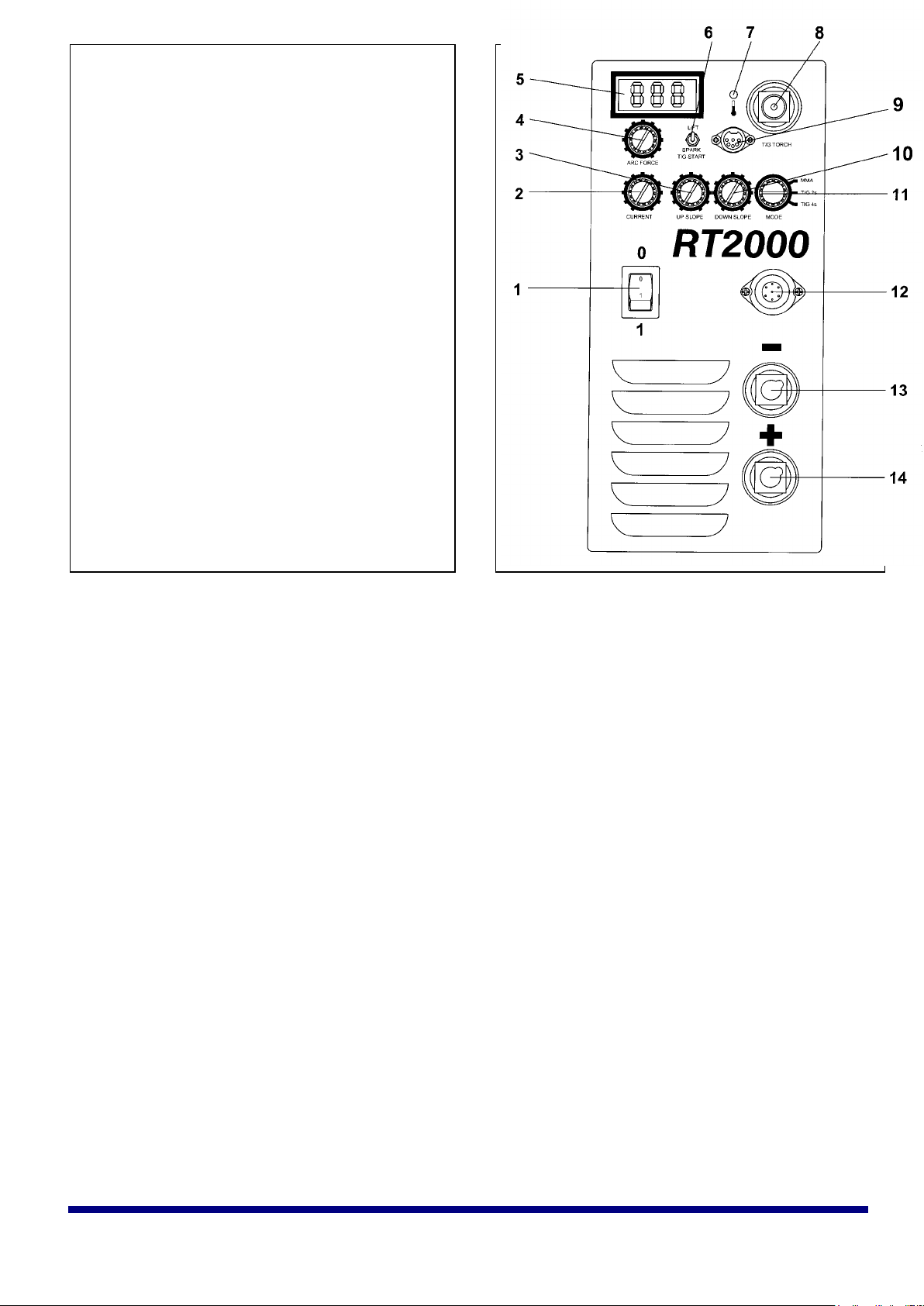
4.2 Description of controls
1 On-Off switch
Switches the machine on and off. Upon switching on
the overload indicator will light and the machines
output will be inhibited, after 15 seconds the
overload indicator will extinguish and the machine is
ready for use.
2 Current control
Use this control to set the output current of the
RT2000.
3 Slope up control
With the slope up control set to minimum the
RT2000 will strike at the current set by the current
control. With the slope up control set to anywhere
but minimum the RT2000 will strike at 5A and then
gradually increase the current to the setting on the
current control, the time this takes is determined by
the position of the slope up control.
4 Arc-force control
Operates in MMA mode only. This control alters
the welding dynamics of the machine to facilitate
welding with different types of welding electrodes
(e.g. general purpose, celulosic, low hydrogen and
iron powder). Turning towards maximum will
increase penetration at the expense of increased
welding splatter, turning towards minimum will
reduce penetration but the arc will be smoother and
less fierce.
5 Digital display
Gives an accurate indication of the welding current.
6 Lift/Spark start selector switch
Switches the machine into either 'HF start' or 'lift
TIG' operation. In HF start a high voltage spark at
the Tungsten’s tip initiates the arc. In lift TIG touch
the Tungsten to the work-piece, press the torch
switch then lift the Tungsten to the welding position,
the arc will initiate.
7 Thermal cut-out indicator
Indicates that the thermal cut-out in the machine has
operated (see paragraph 5.1 in the fault finding and
maintenance section for possible reasons).
8 Power/Gas outlet connector.
For connection of a TIG torch with a combined
power and gas lead. If a TIG torch with a separate
power lead and gas hose is used, an adapter must
be used to connect to this outlet.
9 TIG torch switch connector.
For connecting the TIG torch switch lead.
10 Slope down control.
With the slope down control set to minimum the
current will shut down immediately the torch switch
is released.
With the slope down control set to anywhere but
minimum and the torch switch released, the current
will gradually decrease from the setting on the
current control to 5 amps, whereby the current will
extinguish, the time this takes is determined by the
position of the slope down control.
11 Mode switch
This control switches the RT2000's welding mode.
MMA sets the machine in MMA mode.
TIG 2s sets the machine in 'normal' TIG mode,
whereby pressing the TIG torch switch initiates the
arc and releasing it will extinguish the arc (at the
end of any slope down period set).
TIG 4s sets the machine in 'latch' TIG mode,
whereby pressing the torch switch and releasing it
initiates the arc, pressing and releasing it again will
extinguish the arc (at the end of any slope down
period set).
12 Remote control socket
For connecting external remote control units, these
are the RC300 remote control, the RPC300 pulse
unit and the RFP300 foot pedal. There is no switch
for remote operation, plugging an external unit into
the socket automatically selects remote operation
and disables the internal current control.
13 Negative weld out connector.
Main welding power output connector, negative
polarity.
14 Positive weld out connector
Main welding power output connector, positive
polarity.
15 Gas In connector
(On the rear panel - not illustrated)
Must be connected to the pressure regulator on the
gas cylinder by means of a suitable hose.
RT2000 Instructions for use Page 4
16/05/2014
Page 5
4.3 Operation
4.3.1 MMA Welding
For straight polarity welding, connect the
electrode holder to the positive weld terminal
and the earth return lead to the negative weld
terminal. For reverse polarity welding, reverse
these connections.
Turn the mode switch to 'MMA', the machine is
now in MMA mode.
Turn the mains switch to the on position, the
digital display and the overload indicator will
light. After approximately 15 seconds the
overload indicator will extinguish and the
machine is ready to weld.
While reading the digital display, adjust the
current control to the recommended setting for
the size and type of welding electrode to be
used.
When welding, adjust the Arc-force control to
achieve the arc condition you require.
The RT2000 is suitable for welding all types of
electrodes within the current rating of the
machine, normally up to 3.2 or 4mm depending
on the type of rod..
The RT2000 should never be used with arc-air
gouging or cutting electrodes.
4.3.2 TIG Welding
Connect a hose suitable for use with pure Argon
at a pressure of up to 10 bar (150psi) between
the regulator on the gas cylinder and the gas in
connection on the rear panel of the machine.
Turn the gas cylinder valve and the regulator on
and adjust the regulator to give a working
pressure between 3 and 5 bar. (see paragraph
2.5 'The safe handling of gas cylinders' in
section 2, General precautions for more
information)
Connect the TIG torch power/gas lead to the
TIG torch power/gas connector and the switch
lead to the torch switch socket.
Connect the earth return lead to the +ve weld
terminal.
Turn the mode switch to '2s' or '4s'.(see relevant
paragraph in section 4.2 Description of controls
for more information on the setting of this
control).
Turn the Up slope and Down slope controls to
the settings required. (see relevant paragraph in
section 4.2 Description of controls for more
information on the setting of this control)
Turn the on/off switch to the on position, the
digital display and the overload indicator will
light up. After approximately 15 seconds the
overload indicator will extinguish and the
machine is ready to weld.
While reading the digital display, adjust the
current control to the required setting for the
work being undertaken.
5. Fault finding and
Maintenance
5.1 Machine operation
Most problems with the operation of the RT2000 can
be overcome by following the procedures below.
No digital display on switch on.
Check that the machine is attached to a working
mains supply that it is correctly plugged in and
any isolator switches are turned on.
Have a competent electrician check that there
are no fuses or overload devices interrupted,
that the mains plug is fitted correctly and that
there are no loose wires or connections, check
that there are no breaks in the mains cable.
If all the above appear satisfactory have a
competent maintenance engineer check the
fuses inside the machine. The relevant one in
this case is on the TIG control PCB. This PCB is
located at the top left hand side of the machine.
The fuse is located on the bottom of the PCB
towards the rear of the machine. The fuse rating
is 2 amp, quick blow..
Digital display lit but no output on MMA.
Make sure the mode switch is in the MMA
position.
Make sure that the overload indicator goes off
after 15 seconds. If not see paragraph 'thermal
cut-out indicator' below.
If all the above appear satisfactory, have a
competent maintenance engineer check the
fuses inside the machine. The relevant one in
this case is on the Main control PCB. This PCB
is located at the top right hand side of the
machine. The fuse is located on the top of the
PCB halfway along its length.. The fuse rating is
2 amp, quick blow.
Output on MMA but not on TIG.
Check to see if gas flows when the torch switch
is pressed, if not, check that the torch switch
lead is in good condition that there are no
breaks in the cable and the wires in the plug and
torch switch are still securely attached. Check
that the torch switch plug is connected properly.
If gas flow is present, check the machine works
in 'lift TIG' mode to determine whether the
problem is in the TIG welding mode or that just
the HF is not working.
No HF operation.
have a competent maintenance engineer check
the fuse on the HF PCB. This PCB is located in
the 'U' channel on the top of the machine. The
fuse is located near the top of the PCB toward
the front of the machine. The fuse rating is 2
amps, quick blow.
5.2 MMA Welding Problems
If problems with the RT2000s operation while
MMA welding are experienced, first refer to the
information in paragraphs 3.2 in the installation
section, paragraph 4.2.1 in the operating section
and the fault finding procedure earlier in this
section.
Most problems with the MMA welding procedure
are the result of not setting the correct welding
parameters for the welding rod being used.
All welding rod packets have information on them in
symbolic format , giving suitable current range,
polarity and type of weld (normally called 'position').
If you are in doubt about what these symbols mean,
ask your welding rod supplier to explain them.
Choose an initial current setting towards the middle
of the quoted range and if necessary practice on a
piece of waste material the same type and thickness
as the job to be welded.
5.3 TIG Welding problems
If problems with the RT2000s operation while
TIG welding are experienced, first refer to the
information in paragraphs 3.2 in the installation
section, paragraph 4.2.2 in the operating section
and the fault finding procedure earlier in this
section.
The common problems with TIG welding are poor
striking, porosity and poor appearance of the weld.
If you are experiencing any problems with TIG
welding follow the check list below, this will cure
most problems :-
If the RT2000 is suffering from poor striking,
check that all power leads are connected
properly, check that there is sufficient gas flow
and that the correct gas is being used, check
that the earth clamp is making a good
connection to the work-piece.
If there is porosity in the weld or the final weld is
of poor appearance, check that there is
sufficient gas flow and that the correct gas is
being used, check the condition of the TIG
torch, particularly the gas hose. Make sure that
the collet or gas lens in the torch head is not
blocked in anyway. Check all gas connections
are secure and that there are no leaks, use a
leak detecting spray on all connections if
necessary.
Any welding problems not covered above must be
brought to the attention of a qualified Welding
Engineer, if the problem still persists have the
RT2000 checked by a trained maintenance person.
Thermal cut-out indicator lit
This indicator must be off for normal operation. If on
it indicates that the RT2000 has overheated and the
power stages of the RT2000 have been shut down
so you will get no current output.
In normal climate conditions (below 25C) the
RT2000 has a 100% duty cycle, so operation of the
thermal cut out indicates that the inside of the
machine is likely choked with dust and therefore not
being cooled properly.
In Hot climates (above 25C) It indicates that you
are exceeding the duty cycle of the RT2000, leave
switched on for a few minutes and the RT2000 will
return to normal operation. In this circumstance, do
not switch the RT2000 off as this will stop the
operation of the cooling fan and greatly extend the
cool down period. Frequent tripping of the thermal
cut-out, especially at low current settings is
indicative that the inside of the machine is probably
choked with dust.
For information about cleaning the dust out of
the RT2000 please refer to the relevant part of
section 5.4.2, the three monthly service
schedules.
Any operating problems not covered above
means the RT2000 must be checked by a trained
New-Arc service engineer or returned to the
factory for repair.
RT2000 Instructions for use Page 5
16/05/2014
Page 6

5.4 Maintenance
Note! All Electric shocks are potentially
fatal, switch the machine off and disconnect
from the power supply before undertaking
out any maintenance work.
It is very important that the RT2000 is regularly
maintained. The amount of use and the working
environment must be taken into account when
scheduling the maintenance periods.
Careful use and regular preventative maintenance
will prolong the life of the machine and ensure
trouble free operation.
5.4.1 Weekly
Clean the exterior of the machine
Inspect the machines exterior for obvious signs
of damage.
Check the condition of the welding cable, earth
clamp, welding output and power in connectors
for damage and any sign of over-heating.
Check the condition of the mains lead and plug.
5.4.2 Three monthly
As per the weekly schedule, plus:-
Remove the side covers from the machine.
Remove the build up of dust and debris from
inside the machine, particularly from the Heatsink extrusion, by use of either compressed air
at reduced pressure or an industrial type
vacuum cleaner.
Make a thorough visual inspection of the interior
of the machine; look particularly for pieces of
welding wire, or stubs of old welding rods that
may have got through the cooling air intakes.
Check the condition of the welding output
connectors, look for any signs of discolouration
due to overheating, this is generally caused by
poor connection of the welding power leads due
to loose connection bolts inside the set, or poor
quality welding connectors on the electrode
holder or earth return lead and can be a
common cause of welding set failure.
5.4.3 Annually
As per the three monthly schedules, plus: -
Have the machines calibration checked, if
necessary have the machine re-calibrated by a
New-Arc trained technician.
RT2000 Instructions for use Page 6
16/05/2014
Page 7
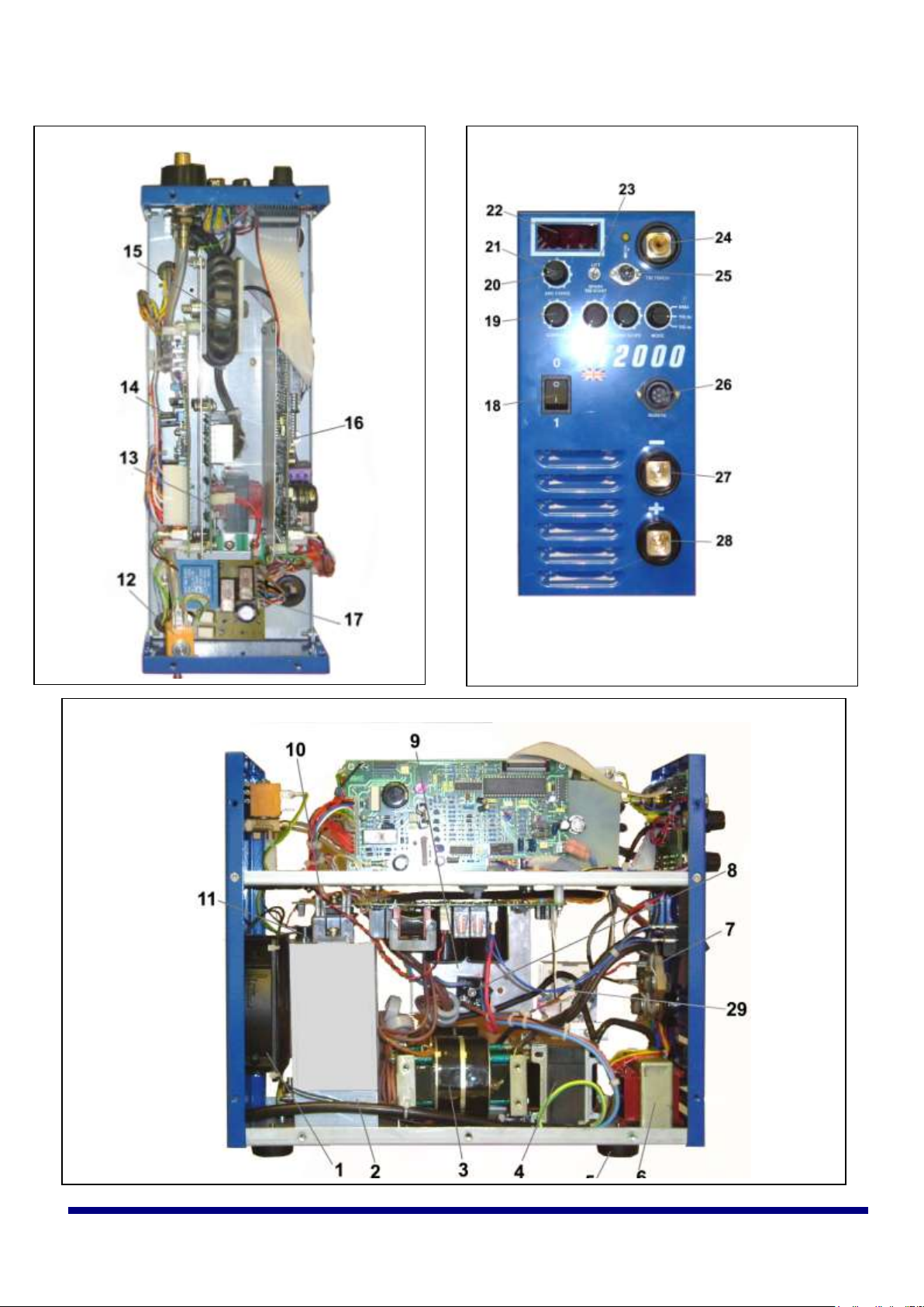
Front View
Top view
Rear Front
6 Parts breakdown
RT2000 Instructions for use Page 7
16/05/2014
Page 8

Item no.
Description
Part no.
1
Cooling fan (230Vac)
M00311/A
2
Diode modules (behind bracket) (2 off)
M60118
3
Main Transformer
M90136
4
Secondary Inductor
M90133A
5
Plastic feet (4 off)
M00096
6
Auxiliary transformer
M00305
7
200A Shunt
M00309
8
Diode Bridge (2 off on Dual voltage machine)
M60089
9
Main Power PCB 230V
M90125/1
Main Power PCB Dual voltage
M90148/1
10
IGBT Module
M60074
11
Thermostat
M00332/80
12
Gas solenoid valve
M00024A
13
HF PCB
M90193
14
Control PCB
M90127
15
HF Inductor
M90411
16
TIG PCB
M90132
17
Auto-switching PCB (Dual voltage only)
M90691
18
Rocker switch
M70069
19
Control/switch PCB
M90080
20
Arc force control potentiometer
M20099
21
Control knobs (5 off)
M00033
22
Digital display assy
M90003
23
Lift/HF selector switch
M70057
24
TIG torch power/gas connector
M00041
25
TIG torch switch socket assy
M90098
26
Remote control socket assy
M90130
27/28
Panel mount Dix type socket (2 off)
M00037
29
24v relay (dual voltage only)
M70026
Misc.
2 amp, 20mm fuse links (Quick blow)
M00274
RT2000 Instructions for use Page 8
16/05/2014
Page 9
6 Wincomblee Road
Walker Riverside
Newcastle upon Tyne
NE6 3PF
Aberdeen Office
Unit 23 Kirkhill Place
Kirkhill Industrial Estate
Dyce
Aberdeen
AB21 0GU
Tel +44 (0)1224 771063
Guarantee
New-Arc Equipment Ltd warrants that its goods and services are guaranteed to meet the specific performance under the stated conditions of
use. New-Arc cannot be held responsible for general wear and tear or for failure occurring due to misuse or abuse arising out of circumstances
outside the stated conditions of use. The stated conditions of use are that considered normal industrial practice and are not exhaustive. Each
machine is identified with a unique serial number and accompanied with the guarantee. New-Arc reserve the right to a) Repair. b)Replace.
c)Authorise the reasonable cost of repair or replacement at an approved New-Arc service agent. d)Credit for any purchased equipment (less
reasonable depreciation for actual use and condition) at its entire discretion. This in no way affects your rights as a consumer. The guarantee is
enclosed with each machine.
Waiver
Whilst every endeavour is made to ensure the details of this document are correct at the date of print. New-Arc accepts no liability for
correctness in respect of any impending change in legislation or health and safety requirements. New-Arc also reserve the right to amend the
detail of the document content without any notification to the consumer. If reference is made to New-Arc while utilising the document for spare
parts purchase or instruction please advise the revision of the document to ensure correctness of information.
RT2000 Instructions for use Page 9
16/05/2014
 Loading...