

Page 1
Spherosyn & Microsyn 300 Quick Install Guide
For the complete manual please download from:
http://newall.com/nms300
Preparation
Prior to beginning the installation the machine should be studied to determine the Encoder(s) position and to
ensure the brackets are suitable, or if custom brackets are required.
In order to reduce erroneous readings caused by machine wear it is recommended that the encoder be tted as
close to the machine lead screw or axial drive shaft as possible.
Warnings
EUROPE
Newall Measurement Systems Ltd.
Technology Gateway, Cornwall Road South
Wigston, Leicester LE18 4XH
United Kingdom
Tel: +44 (0) 116 264 2730
www.newall.co.uk
AMERICAS
Newall Electronics Inc.
USA
Tel: +1 614 771 0213
CHINA & TAIWAN
Sensata Technologies China Co., Ltd
People’s Republic of China
Tel: +86 212 2306 1500
SINGAPORE & KOREA
Sensata Technologies Co., Ltd
Singapore
Tel: +65 647 86 867
JAPAN
Sensata Technologies Japan Ltd.
Japan
Tel: +81 45 277 7120
More information at [email protected] • www.newall.com
Part No: 023-?????-UK
If for any reason the machine axis travel is greater than the actual scale travel, ‘mechanical stops’ should be
tted to the machine to avoid damage caused by over-travel. Newall will not accept responsibility for encoder
damage caused by machine over-travel.
It is important the Scale be kept at least 13mm (0.5”) away from any magnetic sources such as magnetic bases
or chucks.
Assembly Diagrams
DRAWING
NUMBER
31687934
REV.
ISS.
DO NOT SCALE
THIRD ANGLE PROJECTION
IF IN DOUBT ASK
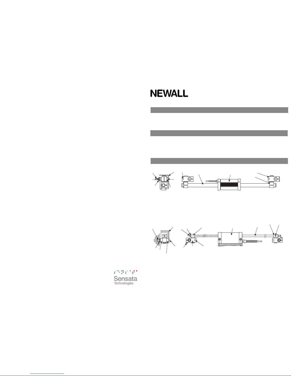
Figure 1 - Spherosyn300 Encoder Assembly
1. Spherosyn300 reader head (1) 6. Support pillar long (2)
2. Spherosyn300 scale (1) 7. Scale cover (1)
3. Scale support link (2) 8. M5 x 20 hex head (6)
4. Scale anchor pin (2) 9. M8 socket button head (2)
5. Support pillar short (2) 10. Spacer washer (2)
Figure 2 - Microsyn300 Encoder Assembly
1. Microsyn300 reader head (1) 9. M3 x 12 hex screw (4)
2. Microsyn300 scale (1) 10. M3 x 12 SHCS (4)
3. End support mounting (1) 11. M6 x 10 socket button head (2)
4. M3 x 16 SHCS (1) 12. Support pin short (2)
5. M3 spring washer (1) 13. Support pin long (2)
6. Support mounting (1) 14. Spacer washer (2)
7. M4 x 5 nylon set screw (1) 15. Scale cover (1)
8. Support link (2)
7
9
10
M8
8
2
4
3
1
5
6
1
7
9
10
8
2
4
3
5
6
11
13
12
14
15
M6
Page 2
Reader head alignment
Scale mounting - double ended
Scale mounting - single end (300mm (12”) travel or less)
Mounting faces
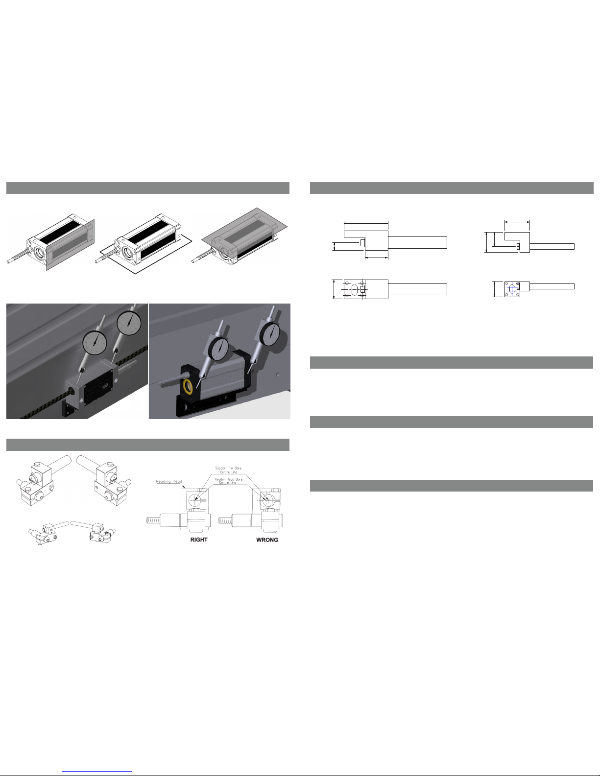
The reader head can be mounted on any 3 of the faces shown in g 3.
Alignment tolerance to machine
The reader head should be mounted with both planes parallel to the axis of travel within ± 0.05mm (0.002”).
See g 4 and 5.
DO NOT SCALE
THIRD ANGLE PROJECTION
IF IN DOUBT ASK
Spherosyn300
Microsyn300
Traverse the machine to its maximum position towards the non cable entry side of the reader head. Slide the
scale through reader head and t assembly (g 6 & 7) onto end of scale. Mark the position of the pillar.
Drill & tap to suit pillar (g 1 & 2). Loosely t assembly to pillar, pass scale through, slide scale forwards and
back whilst tightening the screws until it passes smoothly through head and bracket. Once aligned repeat at the
other end.
Spherosyn300 Microsyn300
SIZE
A4
DRAWING
NUMBER
316-83070
REV.
ISS.
0
DO NOT SCALE
THIRD ANGLE PROJECTION
IF IN DOUBT ASK
For Spherosyn300 remove the white nylon snap rivet from end of the scale.
Once reader head is aligned, slide the scale through and into the single end support and secure into place.
Position the block in the correct position, mark the slot. Drill & tap to suit xing (g 8 & 9). Once secured check
alignment by gently sliding scale in and out through head and block. Grub screws are available for adjustment.
You can single end mount with the standard link, pillar brackets or with the optional single end mount brackets
shown above.
Fitting the scale guard
Cable routing
Final check
Care should be taken to ensure that all cables are routed and secured to the machine avoiding any mechanical
interference with any part of the machine or encoder movement. Routing should also avoid sources of electrical
noise and interference. Cable clamps are supplied.
Note: The armoured cable is an integrated part of the reader head. If the cable becomes damaged this will
require a replacement reader head. Ensure all connectors are located in a position to avoid uid contamination.
Each Encoder includes a protective guard. The guard can be attached to the machine casting or by means of
the scale support pins via the button head screws provided.
For single end mounting use machine faces.
After the guard is attached, move the machine axis to both extents of its travel ensuring that the guard does not
interfere with or rub against the Reader Head.
Prior to putting the linear encoder system into operation after installation, slowly traverse the machine axis to
ensure that all cable routings are correct and machine over-travel cannot occur.
30.00
10.00
58.00
25.40
25.00
14.00
8.00
15.00
 Loading...