

Page 1
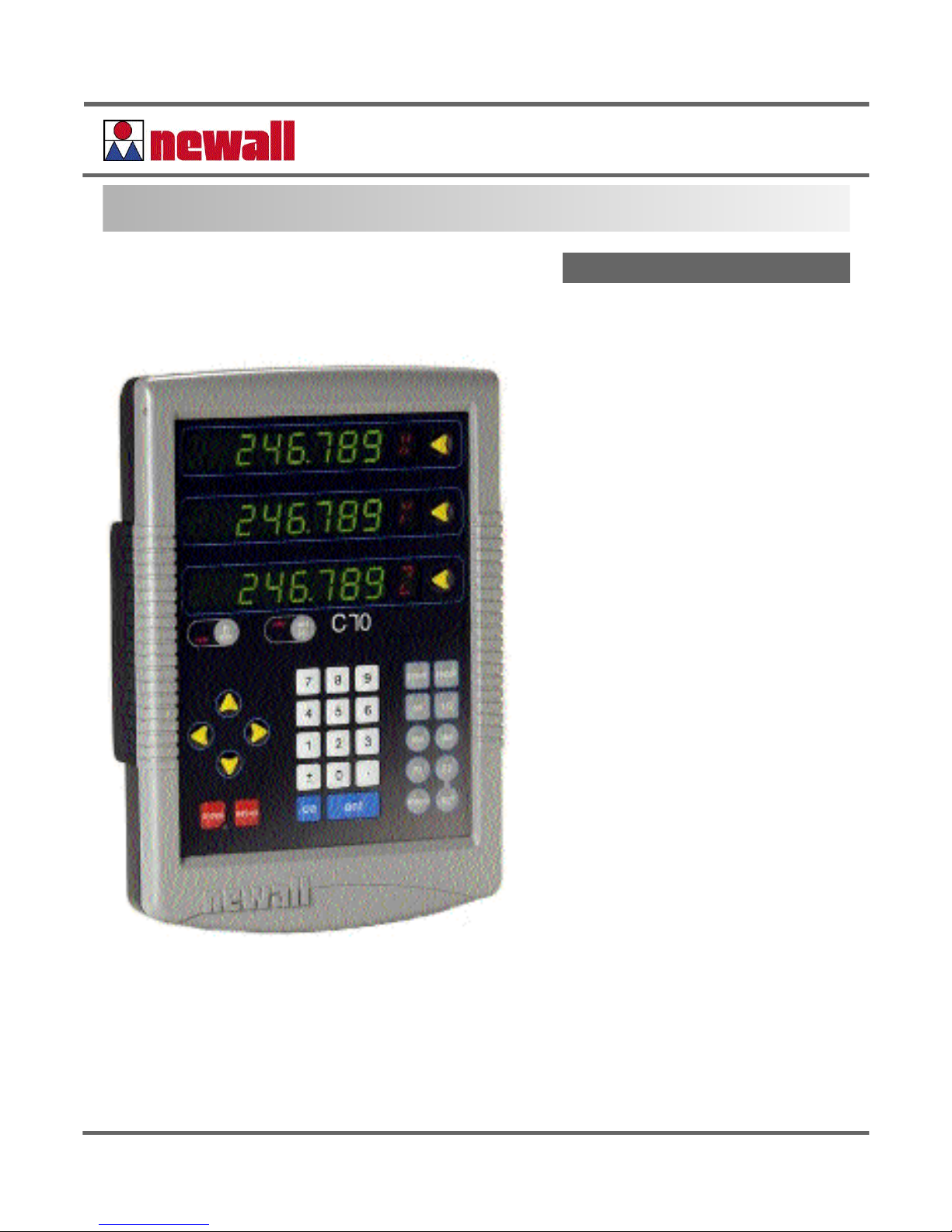
C70 Digital Readout Display
NEWALL MEASUREMENT SYSTEMS LTD
CONTENTS
2 SPECIFICATIONS
3 CONNECTIONS
4 MOUNTING
4 Arm Mounting (Non-adjustable)
4 Arm Mounting (Adjustable)
5 Face Mounting (Adjustable)
5 Lathe Mounting (Adjustable)
6 OPERATION
6 Understanding the Displays
6 Using the Keypad
7 STANDARD FUNCTIONS
7 Setting the Datum for Each Axis
7 Using Digifind
7 Using Centerfind
8 SETUP
8 Using Setup Mode
9 Encoder
10 Radius / Diameter
10 Direction
10 Error Compensation
11 Segmented Error Compensation
12 Linear Error Compensation
13 Zero Approach
14 SPECIAL FUNCTIONS
14 Add / Delete Function
14 Reset
14 Store
15 The Menu Function
16 TROUBLESHOOTING
16 CLEANING
16 NOTES
Page 2
SPECIFICATIONS
SPECIFICATIONS C70 Digital Readout System
Newall Measurement Systems Ltd2
Electrical
EMC and Low Voltage Compliance
BS EN 55022:1998 Class B
BS EN 55024:1998
Power Supply Unit (supplied)
100 - 240V (47 - 63Hz)
External switch-mode
Conforms to Low Voltage Directive
EN 60 950:1992/
A1:1993/ A2:1994/ A3:1996/ A4:1997
Physical
Height
265mm (10.43”)
Width
180mm (7.09”)
Depth (not including connectors)
50mm (1.97”)
Weight
2.9kg (6.38lb)
Environmental
Operating Temperature
0 to 45°C
Storage Temperature
-20 to 70°C
Environmental Conditions
Indoor Use, IP20 (IEC 529)
Relative Humidity
Maximum 80% for temperatures up to 31°C
decreasing linearly to 33% at 45°C
Disposal
At the end of its life, the C70 system should
be disposed of in a safe manner applicable to
electronic goods.
DO NOT BURN.
The casework is suitable for recycling. If you
have any doubt about how to dispose of
your unit, please return it to Newall and we
will provide this service for you.
Input
Three Spherosyn or Microsyn encoders.
Resolutions
Spherosyn or Microsyn 10
(menu selection)
5µm (0.0002”)
10µm (0.0005”)
20µm (0.001”)
50µm (0.002”)
Microsyn 5
(menu selection)
1µm (0.00005”)
2µm (0.0001”)
5µm (0.0002”)
10µm (0.0005”)
NOTE: NEWALL MEASUREMENT SYSTEMS LTD
RESERVES THE RIGHT TO CHANGE SPECIFICATIONS WITHOUT NOTICE.
NOTES
Page 3
C70 Digital Readout System
CONNECTIONS
Newall Measurement Systems Ltd 3
NOTES
DO NOT CONNECT
THIS UNIT DIRECTLY
TO THE MAINS SUPPLY.
If you have a Newall
encoder which is not
fitted with D-type
connector, an adaptor
cable is available.
Part No. 307-80980
Contact your supplier for
details.
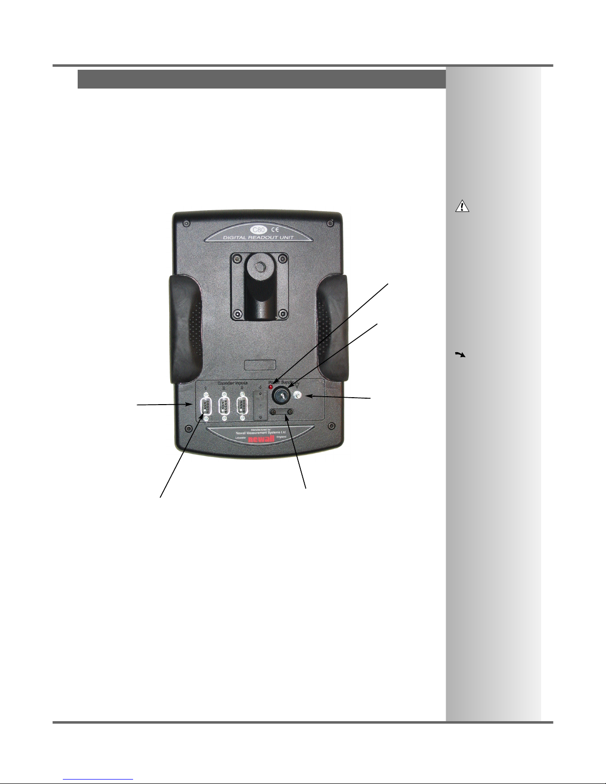
2.5mm
Power Inlet
19 Vdc ±10%
@0.25A
Power
Indicator
Lamp
Encoder Inputs
9-way ‘D’
(All plugs should be
screwed finger tight)
Equipotential
Terminal
(Should be
grounded to
machine)
Cable Anchor
(The power cable
should be secured)
• The C70 is suitable for use only with Newall Spherosyn and Microsyn analogue encoders.
• Ensure that all cables are secured to prevent the connectors from dropping into hazardous
positions when unplugged, for example the floor or coolant tray.
• Ensure that all cables are routed to prevent them from being caught on moving parts.
• Turn off the power before connecting the encoder, by disconnecting the power supply connector.
• Ensure that the C70 is grounded to the machine before turning on the machine supply.
CONNECTIONS
Blanking Plug
(Do not remove
blanking plugs,
Which are used to
prevent accidental
connection of
incorrect encoders)
Page 4
Arm Mounting (Non-adjustable)
Arm Mounting (Adjustable)
Face Mounting (Adjustable)
MOUNTING
MOUNTING, Arm mounting, Face Mounting C70 Digital Readout System
NOTES
Newall Measurement Systems Ltd4
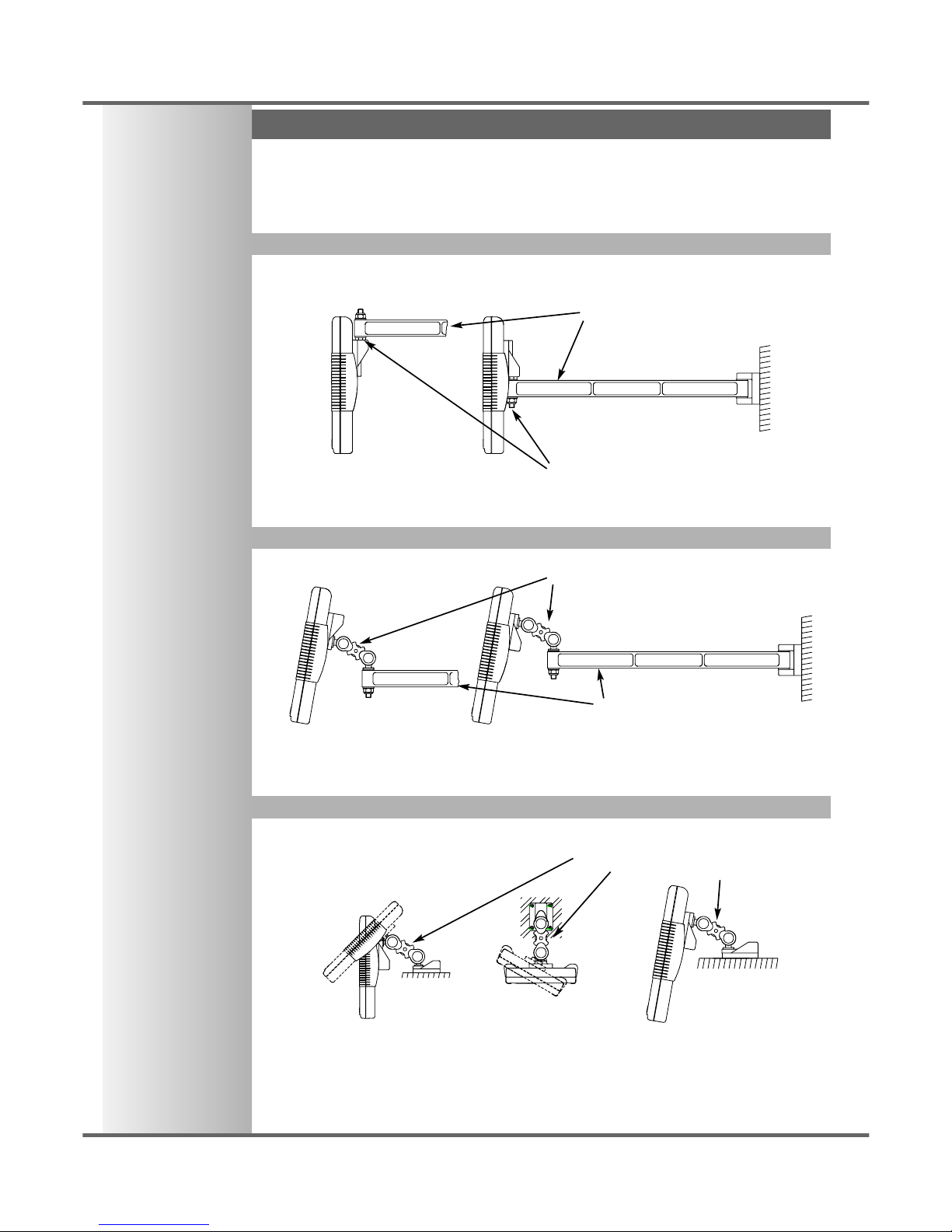
• The C70 can be mounted in a variety of ways, depending on the mounting assemblies purchased
with the unit:
M10 stud & fixings,
supplied as standard
Arm mount adjustable pivot assembly
Part no. 600-80290
Mounting arm assembly
Part no. 294-35670
Mounting arm assembly
Part no. 294-35670
Face mount adjustable pivot assembly
Part no. 600-80270
Page 5
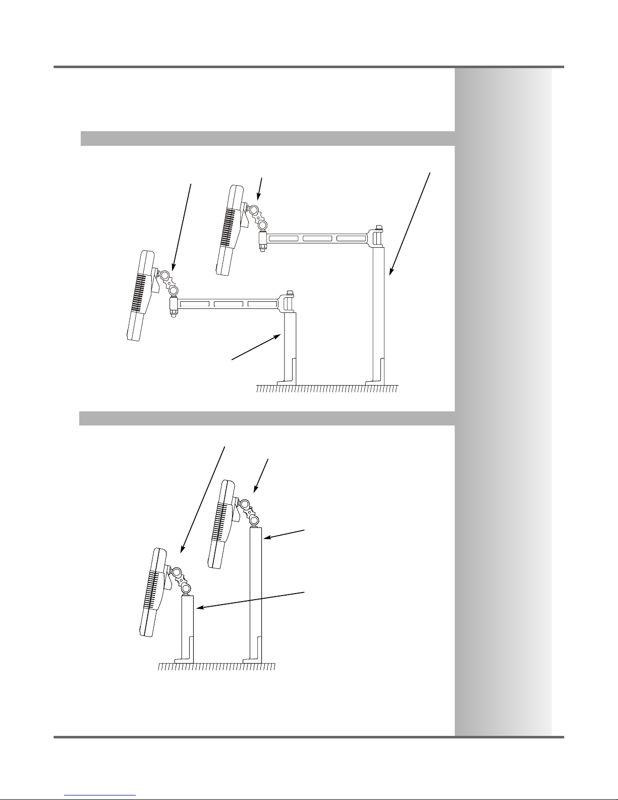
Lathe Mounting (Adjustable)
Lathe Mounting (Adjustable) With Arm Assembly
NOTES
C70 Digital Readout SystemMOUNTING, Face Mounting, Lathe mounting
Newall Measurement Systems Ltd 5
Lathe mount adjustable pivot assembly
Part no. 600-80280
Lathe carriage assembly
Part no. 294-61695
Lathe headstock mount assembly
Part no. 294-60675
Lathe Carriage mount with arm
assembly
Part no. 600-80310
Arm mount adjustable pivot
assembly
Part no. 600-80290
Lathe Headstock with arm
assembly
Part no. 600-80300
Page 6
Understanding the Displays
Using the Keypad
OPERATION
OPERATION, Understanding the Displays, Using the Keypad C70 Digital Readout System
NOTES
At the beginning of each
working session, set the
datum in Absolute
Mode, then switch the
C70 to Incremental
Mode.
By using the C70 in this
way, you will be able to
return the machine to its
absolute datum at any
time, simply by switching
back to Absolute Mode.
Newall Measurement Systems Ltd6
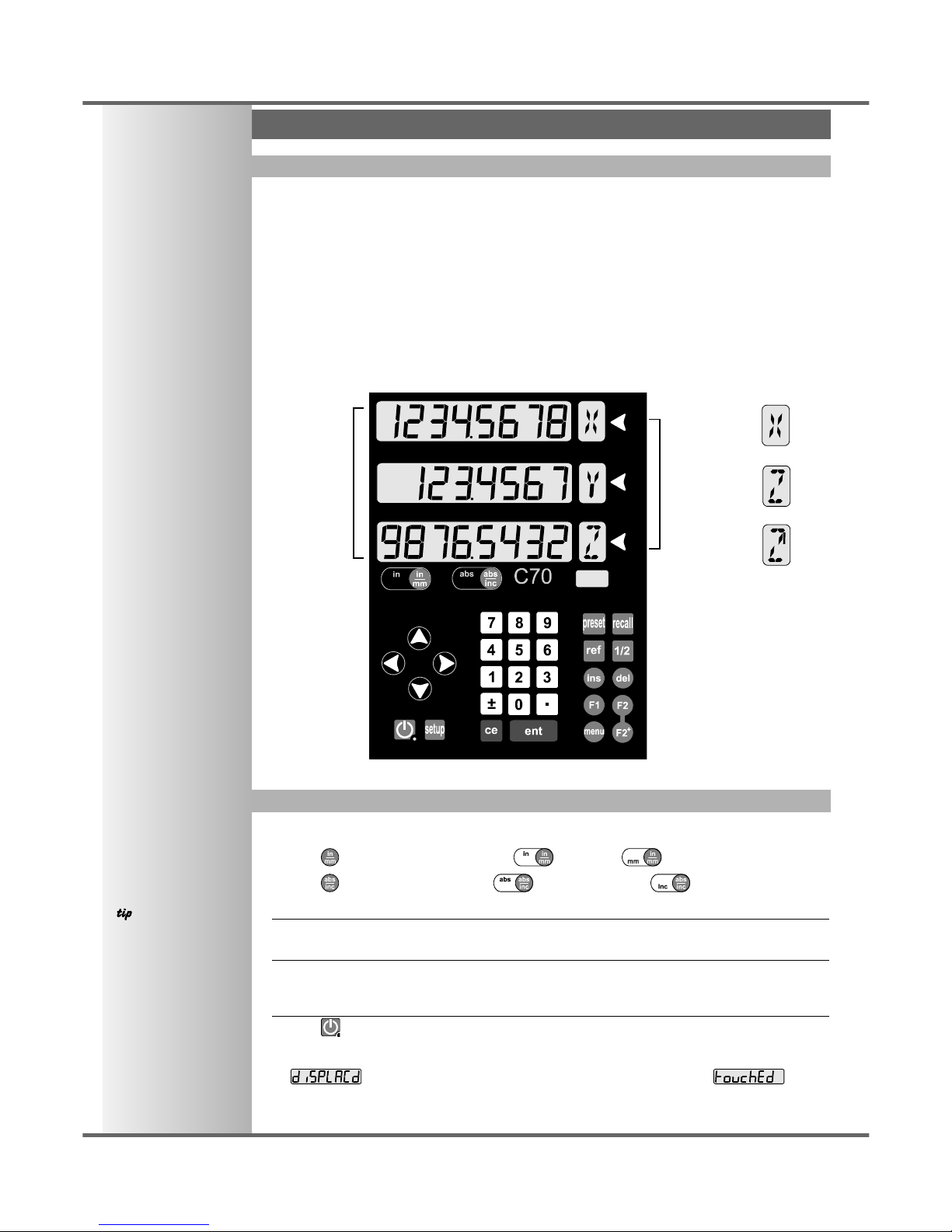
• The three Axis displays normally show the positions of the X, Y and Z axes.
• The three Axis Label displays normally show X, Y and Z, (in Lathe Mode X, Z and Z’).
• While any axis is moving, the Function display shows the Feedrate of the fastest moving axis, and
the feed indicator next to the display will illuminate.
Feedrate is displayed in mm/sec or inches/min, to a resolution on 0.1.
• The lathe and mill indicators will be illuminated depending on whether the lathe or mill functions
or both, are available.
Function Display
Navigation
Keys
Numeric Keys
Function
Keys
Axis
Select
Keys
Axis
Label
Displays
Axis Labels
in Lathe
Mode
Axis
Displays
In normal operation, the keys are used as follows:
• Press to toggle the displays between inches and millimetres.
• Press to toggle the C70 between absolute mode and incremental mode.
Absolute Mode
•
In this mode, the C70 will display the positions of the three axes relative to a fixed datum.
Incremental Mode
•
In this mode, the C70 can be used to display each position relative to the last position. This is also
known as point-to-point use.
Sleep Mode
• Press to temporarily turn off the displays and the keypad.
While the unit is in Sleep Mode, all settings are preserved, but the positions of the three axes are
updated. If any of the axes are moved while in Sleep Mode, the centre display will show
, and if any of the keys are touched, the centre display will show .
Page 7
C70 Digital Readout System
Using Centerfind
Using Digifind
Setting the Datum for Each Axis
STANDARD FUNCTIONS
STANDARD FUNCTIONS, Setting the Datum, Digifind, Centerfind
NOTES
Using Zero redefines the
datum, so it will not be
possible to restore the
old datum.
Using Preset, Recall or
Centerfind will change
the datum - but in
Absolute Mode, Digifind
can still be used to return
to the old datum.
Do not move the
machine when the C70’s
power is off.
When the power is
switched back on again,
the C70 uses Digifind
automatically to reestablish the datum for
each axis.
Digifind works only in
Absolute Mode.
Set the C70 to
incremental before using
Centerfind.
By doing this, you will be
able to return the
machine to its absolute
datum afterwards, simply
by switching back to
Absolute Mode.
Newall Measurement Systems Ltd 7
Zero
• To zero one display at the current position:
Press the Select Key for the axis to be zeroed. All readings will now be relative to this new zero
point.
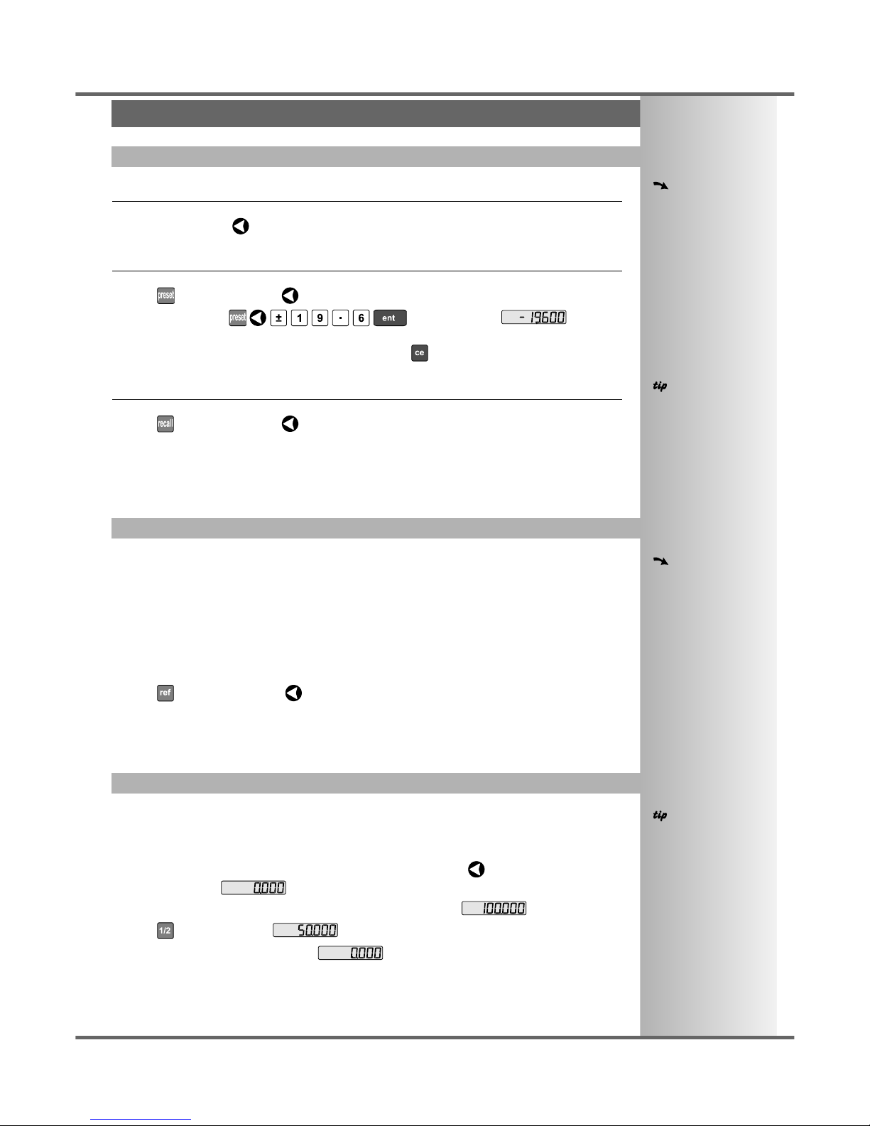
Preset
• To preset one display to a known fixed value:
Press , then the Select Key for the axis to be preset, then enter the value.
For Example: Press to enter the value . All
readings will now be relative to this new value.
• If you make a mistake while entering a number, pressing will clear the entry one character at a
time.
Recall
• To quickly recall the last preset value for an axis:
Press , then the Select Key for the axis to be preset. All readings will now be relative to this
new value.
In the event that a datum is lost, either due to movement following a power failure, or after a fixed point
has been entered by mistake, it can easily be re-established, using Digifind.
In order to use Digifind, the absolute datum for each axis should be marked permanently on the
machine.
• Set the axis close to the marked datum - to within:
6.3mm (0.25”) for a Spherosyn encoder or
2.5mm (0.1”) for a Microsyn encoder.
• Switch the C70 to Absolute mode.
• Press , then the Select Key for the axis to be restored. The display will update to show the
exact distance from the datum.
Centerfind works by halving the distance displayed on the selected axis. It works in either Absolute or
Incremental Mode.
For Example: to find the center of a workpiece that is 100mm wide:
• Set the tool to one edge of the workpiece, and press the Select Key for the axis to be centered.
The display shows .
• Set the tool to the other edge of the workpiece. The display shows .
• Press . The display shows .
• Move the tool until the display shows . This is the center of the workpiece.
Page 8
SETUP
Using Setup Mode
SETUP, Using Setup Mode C70 Digital Readout System
NOTES
Normally, Setup needs to
be done only once, and it
is possible that the
factory default settings
will be suitable and will
not require change.
1
Not all options will be
present, depending on
the setting of other
options.
For example, the Zero
Approach Limit option
will not be present if
Zero Approach is turned
off.
2
The Add Function and
Delete Function options
allow for the download
of programmable
functions from a PC,
connected to the C70 via
a serial lead connected to
Axis 1. The serail lead is
an option and can be
ordered seperately, if
required using Part No.
307-80990. Please
contact Newall for
pricing information
Newall Measurement Systems Ltd8
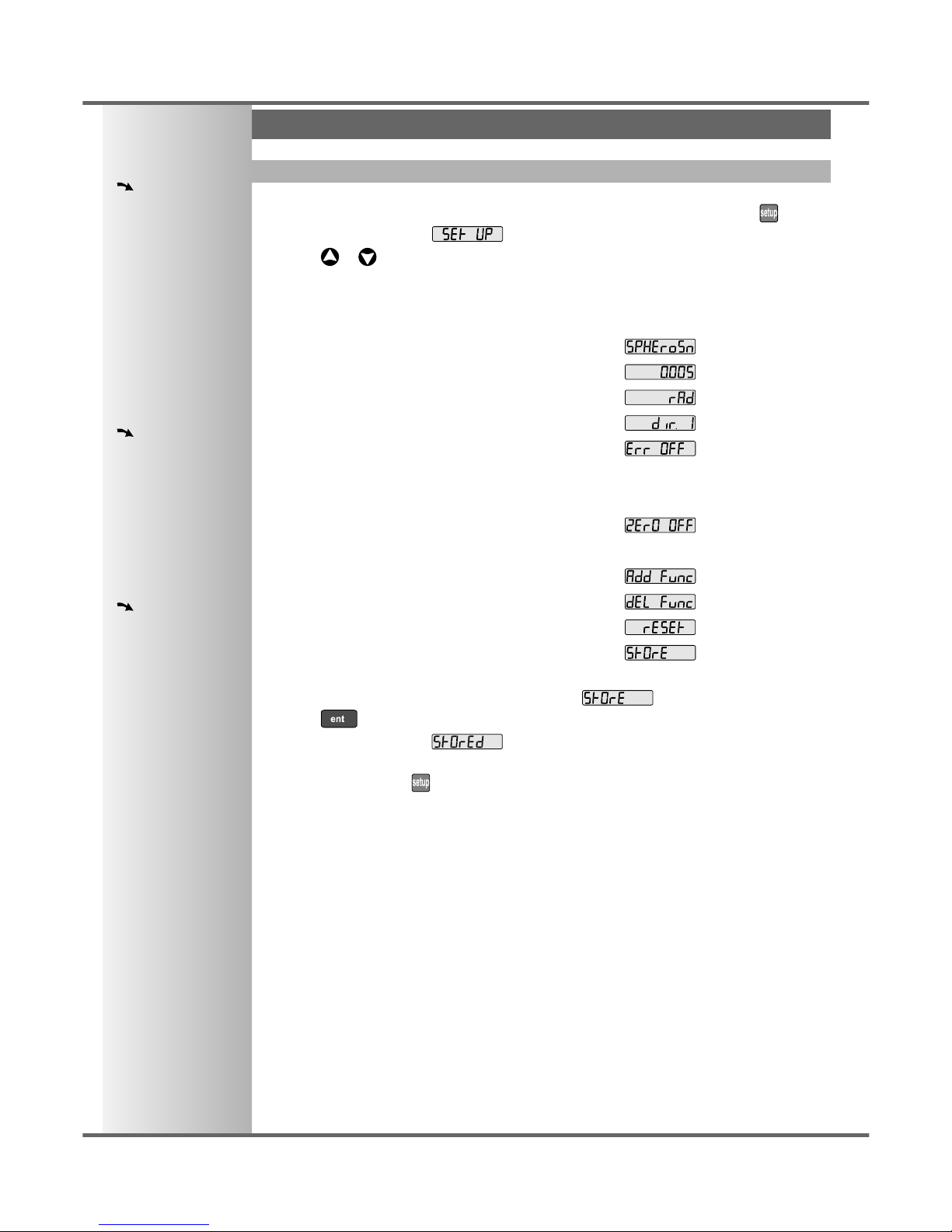
• To enter Setup Mode, first exit from any Special Function that is running, then press .
The centre display shows .
• Press or to cycle up and down the list of options.
The options are listed below, and each is described in detail on the following pages.
Option Default Display
Encoder Type all axes: Spherosyn
Encoder Resolution all axes: 0.005mm
Radius / Diameter all axes: Radius
Direction all axes: 1
Error Compensation all axes: Off
Linear Compensation see note 1
Segmented Compensation see note 1
Zero Approach On / Off all axes: Off
Zero Approach Limit see note 1
Add Function see note 2
Delete Function see note 2
Reset
Store
• When you have finished setting all the options, select .
Press to store any changes made.
The middle display shows for a few seconds, as your settings are stored.
The C70 exits from Setup Mode.
• Alternatively, pressing at any time will exit from Setup Mode and abandon any changes.
Page 9
C70 Digital Readout System
Encoder
SETUP, Unit Information Mode, Machine Type, Encoder
NOTES
The Encoder settings
must match the actual
encoder in use, or the
C70 will not display
correctly.
Newall Measurement Systems Ltd 9
Encoder Type
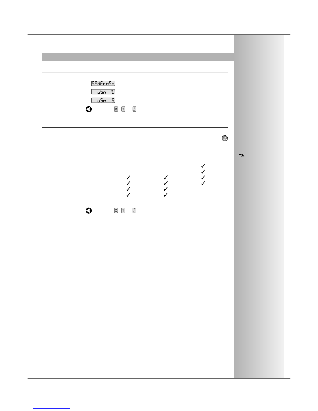
There are three possible settings for each axis:
Spherosyn
Microsyn 10
Microsyn 5
• Press the Select Key next to the , or to cycle between the three settings for each axis.
Encoder Resolution
The Resolution settings available for each axis will depend on the encoder type, and also on the
setting.
Display Spherosyn Microsyn 10 Microsyn 5
mm in
1µm 0.001 0.00005 . . . . . . . . . . . . . . . . . . . . . . . . . . . . . . . . . . . . . . . . .
2µm 0.002 0.0001 . . . . . . . . . . . . . . . . . . . . . . . . . . . . . . . . . . . . . . . . . .
5µm 0.005 0.0002 . . . . . . . . . . . . . . . . . . . . . . . . . . . . . . . . . . . . .
10µm 0.01 0.0005 . . . . . . . . . . . . . . . . . . . . . . . . . . . . . . . . . . . . .
20µm 0.02 0.001 . . . . . . . . . . . . . . . . . . . . . . . . .
50µm 0.05 0.002 . . . . . . . . . . . . . . . . . . . . . . . . .
• Press the Select Key next to the , or to cycle between the four available settings for
each axis.
Page 10
Error Compensation
Direction
Radius / Diameter
SETUP, Radius / Diameter, Direction, Error Compensation C70 Digital Readout System
NOTES
The Diameter setting is
useful for lathes, and
other turning
applications, to display
diameter rather than
radius.
The Direction setting is
quite arbitrary. Set it to
whichever makes most
sense to the machine.
NB, Direction is
dependent on where the
scale is mounted
If Error Compensation is
applied, it is important
that is absolutely correct.
If it is not correct, errors
could be increased rather
than reduced.
After setting up the Error
Compensation, it is
advisable to check its
effect in normal
operation.
Segmented
Compensation need not
be over the entire scale
length.
It can be applied just to a
length of high
importance, or it can be
as small as one segment.
Newall Measurement Systems Ltd10
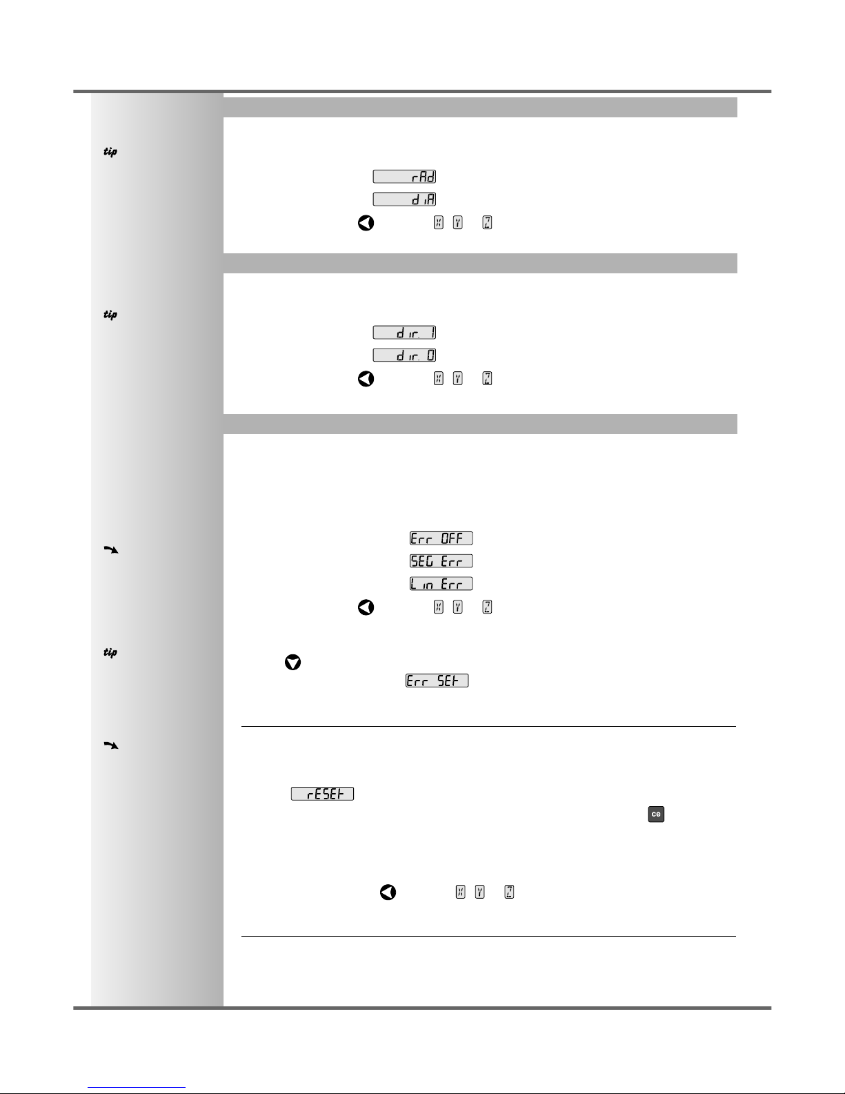
Selecting the Diameter setting causes the C70 to display double the actual movement on any axis.
There are two possible settings for each axis:
Radius
Diameter
• Press the Select Key next to the , or to cycle between the two settings for each axis.
The Direction setting allows you to match the C70 to the actual direction of travel of any axis.
There are two possible settings for each axis:
• Press the Select Key next to the , or to cycle between the two settings for each axis.
Errors can result from a number of sources, including machine wear. Where the degree of error increases
linearly along the length of travel of the scale, Linear Error Compensation should be applied. However,
where the errors are local to an area of travel, the Segmented Error Compensation should be applied.
There are three possible settings for each axis:
Off
Segmented Compensation
Linear Compensation
• Press the Select Key next to the , or to cycle between the three settings for each axis.
If one or more axes are set to Segmented Error Compensation, or Linear Error Compensation, then
the next setup option will be to configure the compensation for each of those axes.
• Press .
The middle display changes to .
Segmented Error Compensation
In this mode, the scale travel for each axis can be broken down into as many as 99 user-defined
segments, with each segment having its own correction factor. The correction factors are calculated by
the C70 by comparison against known, user-supplied standards.
• When power is applied, the display for any axis that is set to use Segmented Compensation
shows .
• If the machine has not been moved since the power was turned off, simply press , and the C70
will restore the last positions recorded.
• Alternatively, set each axis close to the Reference Point - to within:
6.3mm (0.25”) for a Spherosyn encoder or
2.5mm (0.1”) for a Microsyn encoder,
and press the Select Key next to the , or . The C70 will re-establish alignment with the
correction parameters.
Linear Error Compensation
In this mode, a single constant correction factor for each axis can be applied to all displayed
measurements. The correction factor is calculated by the user, and specified in parts per million (ppm).
Values between -9999 and +9999 are allowed.
See pages 11 and 12 for details
on using Linear and Segmented
Error Compensation
Page 11
C70 Digital Readout System
Segmented Error Compensation
SETUP, Segmented Error Compensation
NOTES
Up to 99 segments can
be defined per axis
To take advantage of
Segmented Error
Compensation, you will
need access to a high
accuracy standard, such
as a laser measuring
system.
Error Compensation
initially defaults to off,
with no points set.
If Error Compensation is
set to Off after
Correction Points have
been set, the data is
retained, but not applied.
When Segmented Error
Compensation is set to
On again, the data will
be re-applied.
This procedure must be
carried out in strict
sequence, and in full, to
be valid. There must be
no reversals in direction.
Pressing select key
at steps 1, 2 or 3, will
display the current
uncorrected position
relative to the (Starting
Point).
Do not worry about the
direction of the standard
measurement. eg. 678.9
and -678.9 are treated
the same.
Pressing
will clear
an entry one character at
a time.
After an entry has been
completed by pressing
, pressing
will take you back one
step at a time.
Newall Measurement Systems Ltd 11
If one or more axes are set to Segmented Error Compensation, then the following procedure should
be followed to configure the compensation for each of those axes.
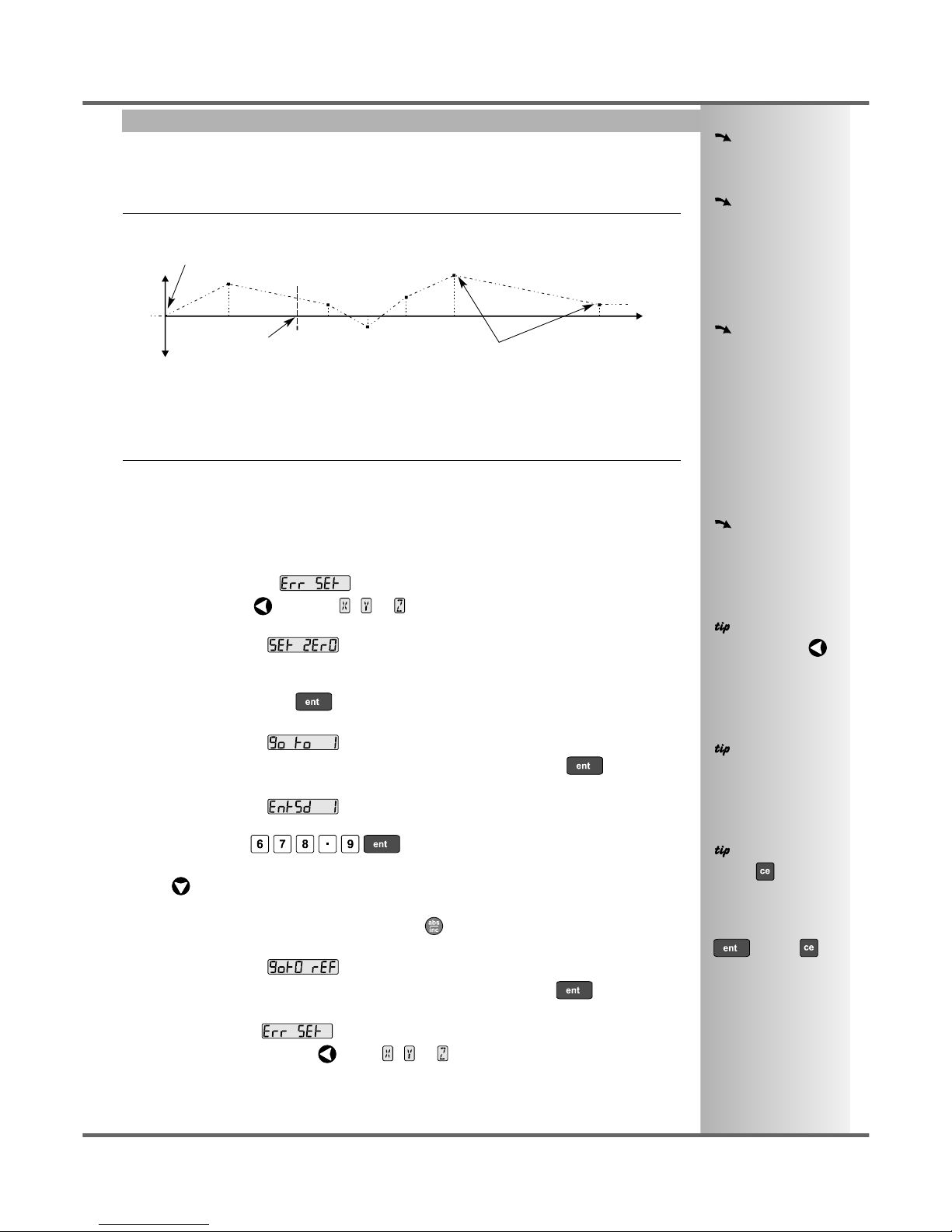
Identification of Correction Parameters
The scale travel is broken down into a number of user-defined segments, each with its own correction
factor, measured against a high-accuracy standard. The following parameters need to be identified:
error
travel
Starting Point - zero
Correction Points
Reference Point
0
1
2
3
4
5
6
Each Correction Point is measured with respect to the Starting Point - zero - which is usually set close
to one end of the scale. The Reference Point can be set anywhere along the scale, and does not need
to coincide with either the absolute datum or any of the correction points. However, it may be convenient
to make the absolute datum and the reference point the same.
Setting the Correction Points
As you follow the steps below, it is essential to take the following precaution:
Always approach the Starting Point, Correction Points and Reference Point from the same
direction. If you do not, then the size of the tool or probe will render the measurement inaccurate.
• Set one or more axes to Segmented Compensation as described on page 10.
The display should show, .
• Press the Select Key next to the , or to enter the setup procedure for each axis to be
configured.
The display changes to .
1 Set the machine to the point you have chosen to the Starting Point, and zero the high-accuracy
standard at this point. Press .
2 The display changes to .
Set the machine to the point you have chosen to be Correction Point 1. Press .
3 The display changes to .
Enter the distance from the Starting Point, as measured by the standard.
For Example: Press to enter a Correction Point of 678.9.
The C70 will calculate and display the correction factor for this point.
• Press to go to the next point.
Repeat steps 2 and 3 for each Correction Point.
When all correction points have been entered, press .
4 The display changes to .
Set the machine to the point you have chosen as the Reference Point. Press .
5 The display returns to .
If required, press the Select Key next to , or to enter the setup procedure for another
axis.
Page 12
Linear Error Compensation
SETUP, Linear Error Compensation C70 Digital Readout System
NOTES
The Correction Factor
cannot be established
while in Setup Mode.
Carry out the
measurements in Normal
Operating Mode, then
enter Setup Mode to set
the Correction Factor.
Only values between
-9999 and 9999 are
allowed.
If you make a mistake
while entering a number,
pressing will clear
the entry one character
at a time.
Newall Measurement Systems Ltd12
A single constant correction factor for each axis is applied to all displayed measurements.
If one or more axes are set to Linear Error Compensation, then the following procedure should be
followed to configure the compensation for each of those axes.
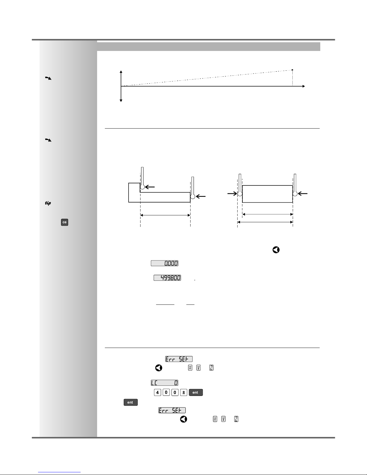
Calculating the Correction Factor
As you follow the steps below, it is essential to take the following precaution:
Either: Use a stepped standard, and approach each edge from the same direction.
Or: If you must approach each edge from opposite directions, then subtract the width of
the tool or measuring probe from the value displayed on the C70.
For Example: To check the scale against a standard which is exactly 500mm wide:
• Set the tool or proble to one edge of the standard, and press the Select Key for the axis to be
corrected.
The display shows .
• Set the tool or probe to the other edge of the standard.
The display shows , .
• Calculate the correction factor:
error = 500.000 - 499.8 = 0.2mm
Correction Factor = = x 1,000,000 = +400 ppm (parts per million)
This value displayed on the C80 needs to be increased to match the standard, so this is a positive
correction factor. If the display had shown 500.2 for the same standard, the correction factor
would be negative -400 ppm.
Setting the Correction Factor
• Set one or more axes to Linear Error Compensation as described on page 10
The display should show, .
• Press the Select Key next to the , or to enter the setup procedure for each axis to be
configured.
The display shows , or a previously entered value.
• For Example: Press to enter a Correction Factor of -400 ppm.
• Press again.
The display returns to .
If required, press the Select Key next to the , or to enter the setup procedure for
another axis.
0.2
500
error
standard
error
travel
standard distance
measured distance
= standard distance
tool or
probe
tool or
probe
measured distance
Page 13
C70 Digital Readout System
Zero Approach
SETUP, Zero Approach
NOTES
Newall Measurement Systems Ltd 13
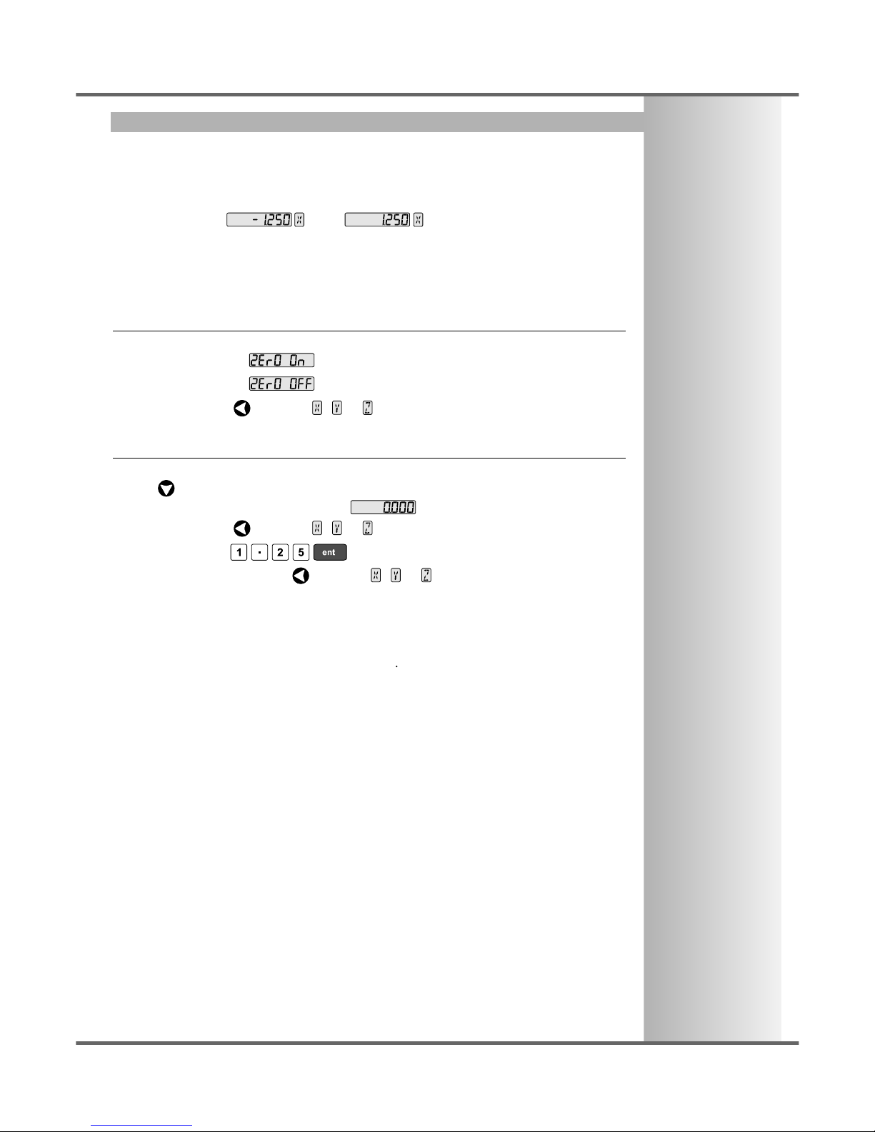
This setting provides a visual indication that one or more axes are approaching zero, by flashing the
Axis Label display.
For Example: If Zero Approach is turned on for the X axis, with a Zero Approach Limit of 1.25, then
the axis label display will flash for values
from to
• When the axis is within:
0.05mm (0.002”) for a Spherosyn encoder or
0.025mm (0.001”) for a Microsyn encoder
the display will stop flashing.
Zero Approach On / Off
There are two possible settings for each axis:
Zero Approach On
Zero Approach Off
• Press the Select Key next to the , or to cycle between the two settings for each axis.
Zero Approach Limit
This setting allows you to choose how close to zero the axis needs to be for the display to flash.
• Press after setting Zero Approach On / Off.
The displays for the selected axes change to or a previously entered value.
• Press the Select Key next to the , or to choose which axis to edit.
• For Example: Press to enter a limit of 1.25.
• If required, press the Select Key next to the , or to enter the limit for another axis.
Page 14
Store
Reset
Add / Delete Function
SPECIAL FUNCTIONS, Add /Delete Function, Reset, Store C70 Digital Readout System
NOTES
THE SERIAL
PROGRAMMING LEAD
IS SPECIFICALLY
DESIGNED FOR
CONNECTION TO
C-SERIES DIGITAL
READOUTS.
INCORRECT
CONNECTION MAY
CAUSE FAILURE.
USE RESET WITH
CAUTION.
ALL STORED SETTINGS
WILL BE LOST IF THIS
FUNCTION IS USED
ALL RESTORE
CHANGES ARE SAVED
IMMEDIATELY
Reset will take
approximately15
seconds
Newall Measurement Systems Ltd14
These two options allow you to download programmable functions from a PC connected to the C70 via
a serial lead connected to axis 1. This serial lead is an option and can be ordered seperately if require
using Part No. 307-80990. Please contact Newall for pricing information.
New functions are available as Internet downloads and can be found on the Newall
Website:www.newall.com
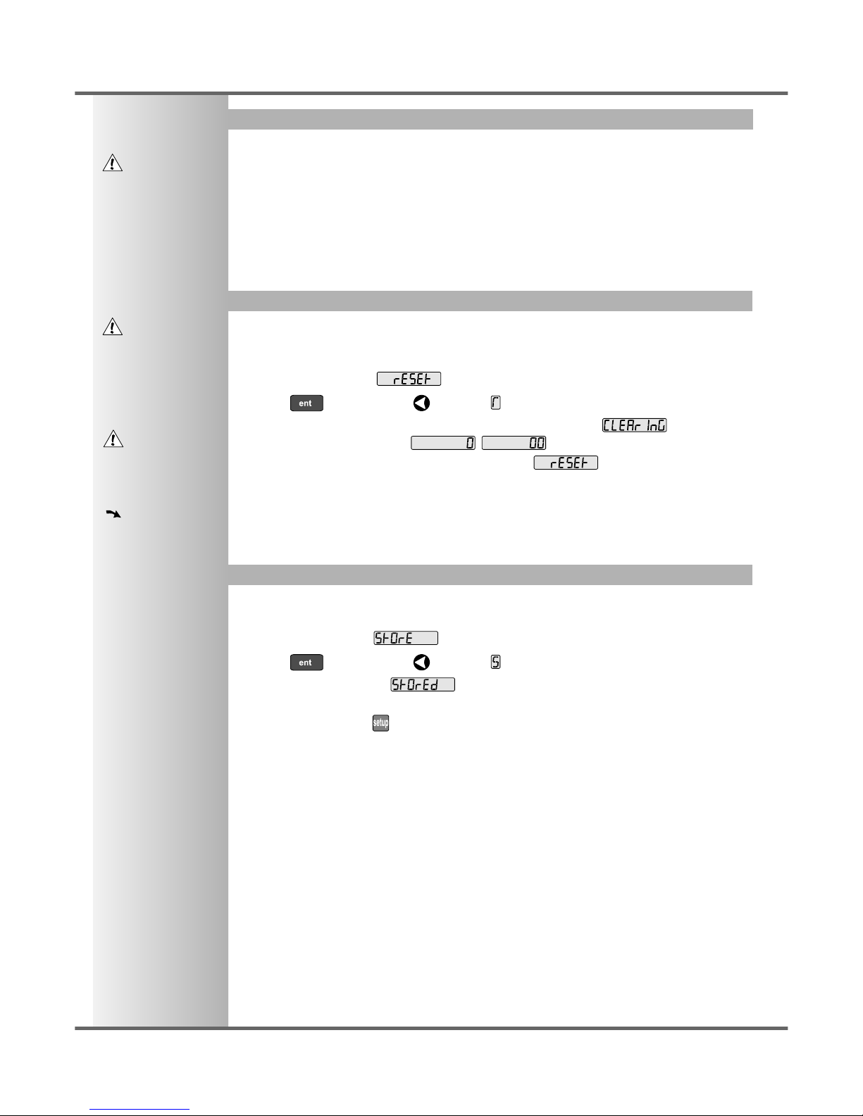
This will restore all settings to their factory defaults, and should, therefore, be used only if
absolutely necessary.
The middle display shows:
• Press or the select key next to the to select the Reset function.
• While all the stored settings are being erased, the top display shows: ,
and the middle display shows , etc.
• When Reset has finished the middle display returns to:
The C80 remains in Setup Mode.
This will store all settings and exit to Normal Operating Mode.
The middle display shows
• Press or the select key next to the to select the Store function.
• The middle display shows for a few seconds, as your settings are stored.
The C70 exits from Setup Mode.
• Alternatively, pressing at any time will exit from Setup Mode and abandon any changes.
Page 15
C70 Digital Readout System
The Menu Function
SPECIAL FUNCTIONS, The Menu Function
If certain functions are
running when you
press , then in place
of the function name,
the display will show
.
Press again to turn
the Menu off, if you
want to allocate a
different function to that
function key, then turn
the function off before
trying again.S
Newall Measurement Systems Ltd 15
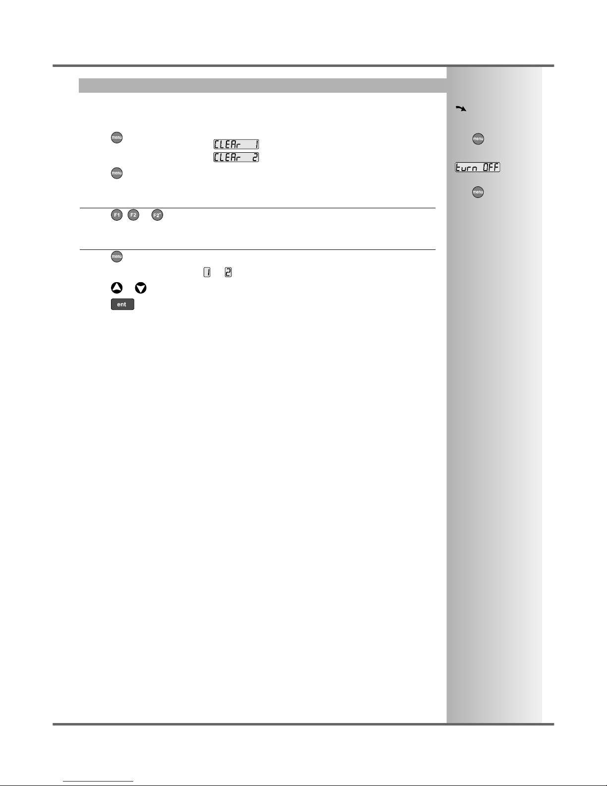
Only two Special Functions are available for use at any one time.
To find out which function is allocated to each key:
• Press to see the Menu.
The display shows,
• Press again to turn the Menu off.
To use a function:
• Press , or , according to the instructions given later in this guide.
To allocate a function to a key:
• Press .
• Press the Select Key next to the or to choose which function key to edit.
• Press or to cycle up and down the list of Special Functions.
• Press to allocate the selected Special Function to the function key.
Note: The C70 has no special functions programmed as standard. Please see the Newall Website:
www.newall.com to see what new features may be available
Page 16
C70 Digital Readout System
Newall Measurement Systems Ltd16
CLEANING
TROUBLESHOOTING
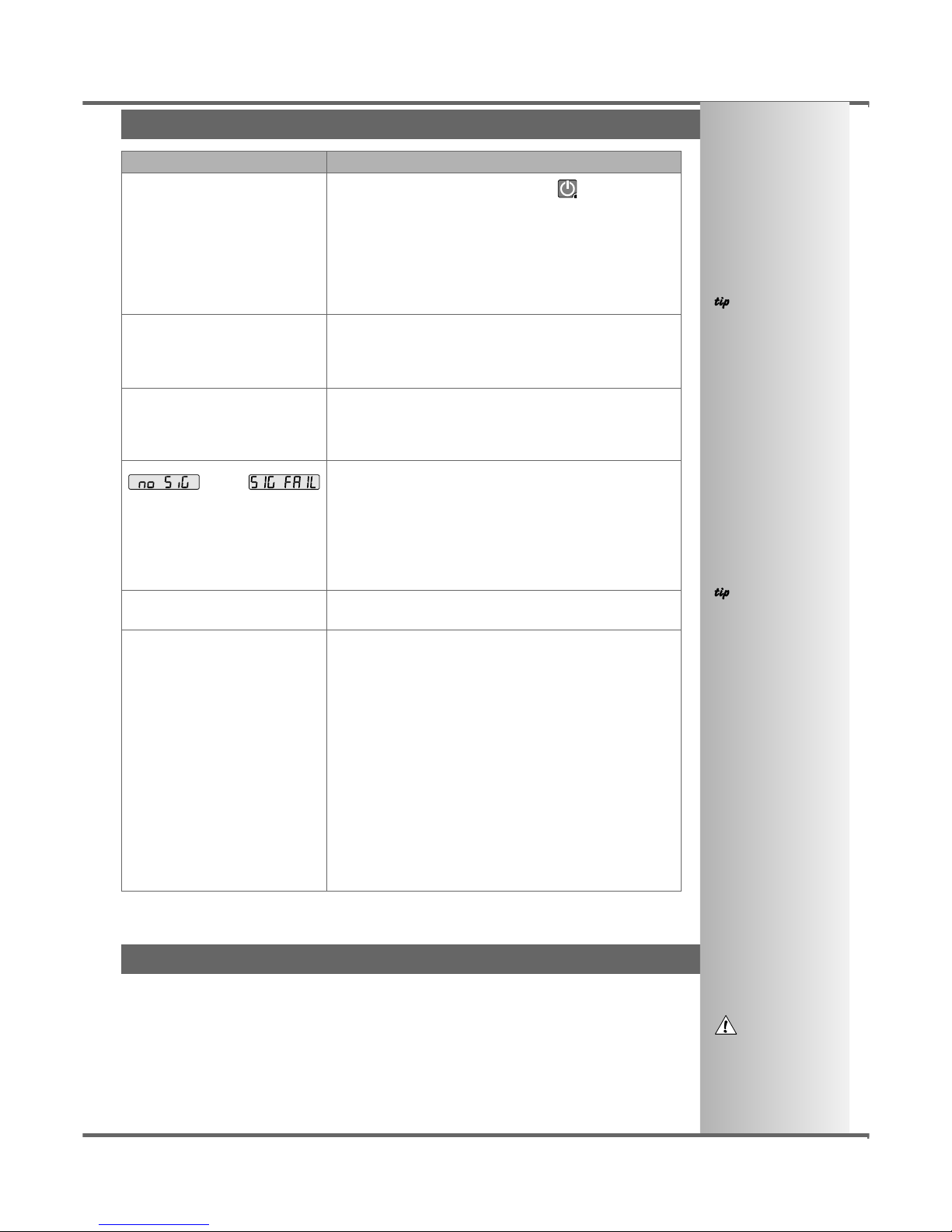
The display is blank.
The display works, but resets
from time to time without any
keys being pressed.
The display works, but gives
erratic readings, the last digit
jitters or the measurements
jump to new figures
unexpectedly.
or
appears in the display.
The unit will not respond to any
key presses.
Readings are incorrect
• The C70 may be in Sleep Mode. Press .
• Check that the power supply is correctly connected to a
working mains outlet.
• Check that the power supply cables are not damaged.
• Check that the power supply voltage is 19Vdc ±10%.
• Disconnect all encoder cables. A defective encoder can
prevent the C70 from working.
• Check power supply lead on rear of C70 display to ensure
that is it illuminated
• This suggests either that the supply voltage is too low, or
that the power supply or mains supply has an intermittent
fault.
• Check that the power supply voltage is 19Vdc ±10%.
• Check that all connections are sound.
• This suggests that there may be a poor earth (ground)
connection.
• Both the C70 , and the machine on which it is installed,
must have proper earth (ground) connections. (see page 3)
• There may be a problem with the encoder (see below).
• This indicates that the unit is not receiving a proper signal
from the encoder.
• Check that the encoder connections are sound.
• Check that there is no damage to the connectors or to the
encoder.
• Switch the C70 off and back on again.
• Swap the encoder to another axis to confirm whether the
encoder or the C70 is at fault (see tip).
• Disconnect the C70 from it’s power supply, wait 15
seconds and then reconnect.
• Check Encoder Type to ensure correct selection.
• Check the Radius / Diameter setting. The Diameter setting
will cause the axis to read double.
• Check Error Compensation factors.
• If using Segmented Error Compensation, verify the datum
position.
• Swap the encoder to another axis to confirm whether the
encoder or the C70 is at fault (see tip).
• Check that there is no damage to the encoder or its cable.
• Check that the encoder is fixed firmly and aligned correctly,
as described in the Spherosyn / Microsyn Installation
manual.
• Check that there is no binding on the scale. With the scale
brackets slightly loosened, you should be able to slide the
scale back and forth with minimal resistance.
• If you have a Spherosyn scale, check that the scale is not
bent, by removing it and rolling it on a flat surface.
SolutionsSymptom
NOTES
Providing the machine
has not been moved
more than:
6.3mm (0.25”) for a
Spherosyn encoder or
2.5mm (0.1”) for a
Microsyn encoder
the datum position will
not be lost by switching
the power off and back
on again.
When swapping
encoders to trace a fault:
1
Check that two axes are
set to the correct
encoder types.
2
Move the encoder from
the malfunctioning axis
to a working axis.
If the fault stays with the
same encoder, then the
encoder is at fault. If the
fault does not follw with
the encoder the C70 is at
fault
FOLLOW THESE
INSTRUCTIONS
CAREFULLY TO AVOID
DAMAGE TO THE C70.
TROUBLESHOOTING, CLEANING
If the solutions suggested above do not solve your problem, contact Newall for further instruction.
• Disconnect the power supply from the C70 before cleaning.
• Do not use corrosive or abrasive cleaning materials.
• Do not use compressed air.
• Apply a small amount of mild soap to a lint-free cloth. Use this to wipe over the case and keypad,
taking care not to allow fluid into the connectors.
 Loading...