

Page 1
AC-12100E
PORT ABLE AIR CONDITIONER
OW NERS MANU AL
’
Page 2
CONTENTS
Welcome
Introduction........................................................................................................................................2
SAFETY PRECAUTIONS
Safety rules .......................................................................................................................................3
Operating condition ...........................................................................................................................3
Electrical information .........................................................................................................................4
IDENTIFICATION OF PARTS
Accessories .......................................................................................................................................4
Names of parts...................................................................................................................................5
AIR CONDITIONER FEATURES
Electronic control operating instructions ...........................................................................................6
OPERATING INSTRUCTIONS
Operating instructions .......................................................................................................................7
INSTALLATION INSTRUCTIONS
Location ............................................................................................................................................9
Window kit installation ......................................................................................................................9
Exhaust hose installation ................................................................................................................12
Water drainage ................................................................................................................................13
CARE AND MAINTENANCE
Care and maintenance ....................................................................................................................14
TROUBLESHOOTING TIPS
Troubleshooting . ..............................................................................................................................15
NOTE
The rating data indicated on the energy label is based
on the testing condition of installing the un-extended
air exhaust duct without adaptor A & B (The duct and
the adaptor A & B are listed in the accessories chart
of the Instruction Manual).
1
Page 3
INTRODUCTION
When using this air conditioner, please keep the following information in mind:
DISPOSAL: Do not dispose of this product as unsorted municipal waste. Collection of
such waste separately for special treatment is necessary.
It is prohibited to dispose of this appliance in domestic household waste.
For disposal, the following options may be available:
A) The municipality has established collection systems, where electronic waste can be
bedisposed of free of charge to the user.
B) When buying a new product, the retailer will take back the old product freeof charge.
C) The manufacture will take back the old appliance for disposal free of charge to the
user.
D) As old products contain valuable resources, they can be sold to scrap metal dealers.
Disposing of waste in forests and landscapes endangers your health when hazardous
substances leak into the ground-water and find their way into the food chain.
2
Page 4
SAFETY PRECAUTIONS
Safety rules
To prevent injury to the user or other people and property damage, the following instructions must be
followed. Incorrect operation due to ignoring of instructions may cause harm or damage.
Always Do This:
!
Your air conditioner should be used in such a way
that it is protected from moisture. e.g. condensation,
splashed water, etc. Do not place or store your air
conditioner where it can fall or be pulled into water
or any other liquid. If your unit becomes wet, unplug
immediately. Always transport your air conditioner in
a vertical position and stand on a stable, level
surface during use.
Turn off the product when not in use.
Always contact a qualified person to carry out
repairs. If the supply cord is damaged it must be
repaired by a qualified technician.
Keep an air path of at least 30cm all around the
unit from walls, furniture and curtains.
If the air conditioner is knocked over during use,
turn off the unit and unplug from the power supply
immediately.
Energy Saving Tips:
Do not operate your air conditioner in a wet room
such as a bathroom or laundry room.
Do not touch the unit with wet or damp hands or
when barefoot.
Do not press the buttons on the control panel with
anything other than your fingers.
Do not remove any fixed covers. Never use this
appliance if it is not working properly, or if it has
been dropped or damaged.
Never use the plug to start and stop the unit. Always
use the switch on the control panel.
Do not cover or obstruct the inlet or outlet grilles.
Do not use hazardous chemicals to clean or come
into contact with the unit. Do not use the unit in the
presence of inflammable substances or vapour such
as alcohol, insecticides, gasoline,etc.
Do not allow children to operate the unit
unsupervised.
Do not use this product for functions other than
those described in this instruction manual.
Never Do This:
Use the unit in the recommended room size.
Locate the unit where furniture cannot obstruct the air flow.
Keep blinds/curtains closed during the sunniest part of the day.
Keep the filters clean.
Keep doors and windows closed to keep cool air in and warm air out.
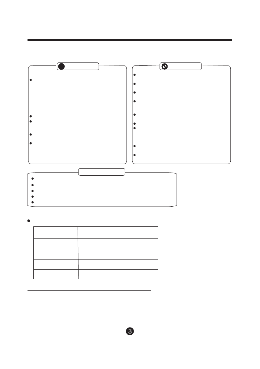
Operating condition
The air conditioner must be operated within the temperature range indicated below:
MODE ROOM TEMPERATURE
COOL
DRY
HEAT(heat pump type)
HEAT(electrical heat type)
62°F (17°C)~ 95°F (35°C)
55°F (13°C)~95°F (35°C)
41°F (5°C)~88°F (30°C)
<88°F/30°C
Note: Performance may be reduced outside of these operating temperatures.
Suggested tools for window kit installation
1. Screwdriver(medium size Phillips)
2. Tape measure or ruler
3. Knife or scissors
4. Saw (in the event that the window kit needs to be cut down in size because
the window is too narrow for direct installation)
3
Page 5
IDENTIFICATION OF PARTS
WARNING
For your safety
Do not store or use gasoline or other flammable vapors and liquids in the vicinity of this or any other
appliance.
Avoid fire hazard or electric shock. Do not use an extension cord or an adaptor plug. Do not remove
any prong from the power cord.
WARNING
Electrical Information
Be sure the electrical service is adequate for the model you have chosen. This information can be found
on the serial plate, which is located on the side of the cabinet and behind the grille.
Be sure the air conditioner is properly grounded. To minimize shock and fire hazards, proper grounding is
important. The power cord is equipped with a three-prong grounding plug for protection against shock
hazards.
Your air conditioner must be used in a properly grounded wall receptacle. If the wall receptacle you intend
to use is not adequately grounded or protected by a time delay fuse or circuit breaker, have a qualified
electrician install the proper receptacle.
Ensure the receptacle is accessible after the unit installation.
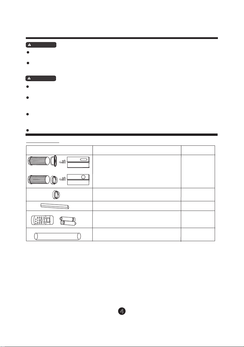
Accessories
PARTS :
M E
S
W
OIN
O
FL
D
NI
G
M
O O
R E
LW
E N
E
E
C
S L
O
O
N
L
D
T
/ F
O
O
O
F
C
I AL
M
S
K
E
P
Y
D
F
Y
A
T R
T
N
I
I
M
M
T
S
E O
U
E ON
P
R
E
BR
E
O
F
D
F
or
AUTO
COOL
DR
HEAT
Y
S
E
T
T
E
M
P
TE
E
R
MP
A
T ER
U
(
C
)
FN
H
MD
L
A
O
E
GI
W
H
PARTS NAME : QUANTITY :
Exhaust hose (supplied), adapter B
(round mouth or flat month,
depending on models) and Window
Slider Kit and bolt
Adaptor B (round mouth)
Foam seal 3/pc
Remote Controller and Battery
(For remote control models only)
1 set
1 set
3 pc
1set
NOTE:
Drain hose
All the illustrations in this manual are for explanation purpose only. Your air conditioner
may be slightly different. The actual shape shall prevail.
1pc
4
Page 6
IDENTIFICATION OF PARTS
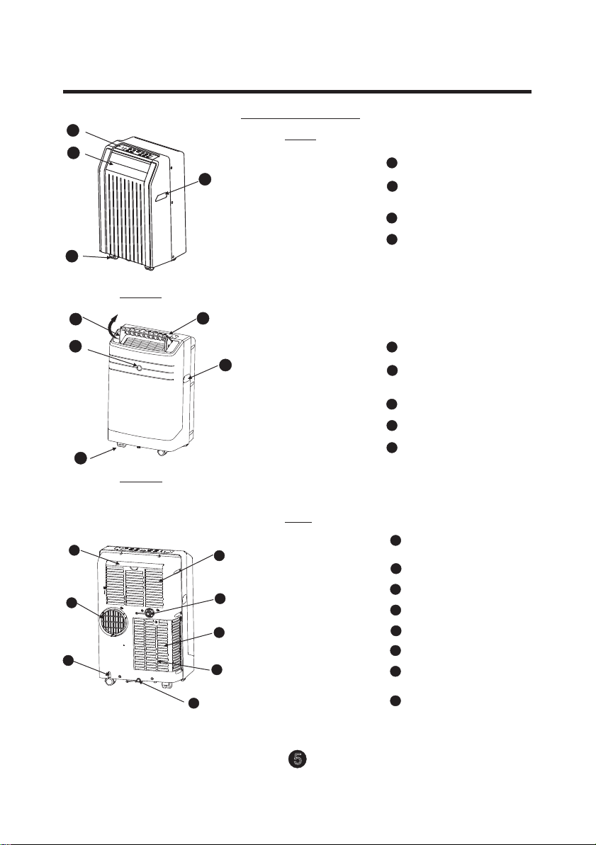
NAMES OF PARTS
1
2
4
3
Fig.1
Model A
Front
Operation Panel
1
Horizontal Louver Blade
2
(Swing automatically)
3
Caster
4
Carrying Handle
(Both sides)
2
3
4
Model B
1
Fig.2
Operation Panel
1
5
Horizontal Louver Blade
2
(Manual)
Remote signal receptor
3
4
Caster
5
Carrying Handle
(Both)
Rear
Upper Air Filter
6
6
7
8
9
10
11
12
13
Fig.3
(Behind the grille)
Air Outlet
7
Power Cord Outlet
8
Air Intake
9
Drain Outlet
10
Air intake
11
Lower Air Filter
12
(Behind the grille)
13
Bottom Tray Drain Outlet
5
Page 7

AIR CONDITIONER FEATURES
ELECTRONIC CONTROL OPERATING INSTRUCTIONS
Before you begin, thoroughly familiarize yourself with the control panel and remote controller
and all its functions, then follow the symbol for the functions you desire.
The unit can be controlled by the unit control panel alone or with the remote controller .
NOTE: This manual does not include remote control operation instructions.Please see the
Remote Control Operation Instructions packed with the unit for details.
OPERATION PANEL OF THE AIR CONDITIONER
(Available only on
models with auto
swing feature.)
6
8
7
6
Remote Signal Receptor
(Some models have the
signal receptor on the
front panel , Fig.2)
SWI NG
AUT O
COO L
HEAT
DRY
FAN
Fig. 4
MODE select button
1
Selects the appropriate operating mode.
Each time you press the button, a mode
is selected in a sequence that goes from
AUTO, COOL, DRY, FAN and HEAT(except
cooling only models). The mode indicator light
illuminates under the different mode settings
2
TIMER button
Used to initiate the AUTO ON start time and
AUTO OFF stop time program, in conjunction
with the & buttons.
3
POWER button
MOD E
1
2
Power on/off.
SLEEP button
4
Used to initiate the SLEEP function.
5
FAN button
Control the fan speed. Press to select the fan
speed in four steps-LOW, MED, HI and AUTO.
The fan speed indicator light illuminates under
different fan settings except AUTO speed. When
the auto fan speed is selected, all the fan indicator
lightsturn dark.
C
F
TIM ER ON
TIM ER OFF
3
UP( ) and DOWN( ) buttons
6
Used to adjust (increasing/decreasing)
temperature settings(2°F/ 1°C increments)
in a range of 62°F (17°C) to 88°F (30°C)
orthe TIMER setting in a range of 0~24hrs..
NOTE: The control is capable of displaying
temperature in degrees Fahrenheit or degrees
Celsius. To convert from one to the other, press
and hold the Up and Down buttons at the same
time, for 3 seconds.
7
LED Display
Shows the set temperature in°F and°C and
the auto-timer settings.
While on DRY and FAN modes, it shows
the room temperature.
Error codes:
E1- Room temperature sensor error-
Unplug the unit and plug it back in.
If error repeats, call for service.
E2- Evaporator temperature sensor error Unplug the unit and plug it back in.
If error repeats, call for service.
E4- Display panel communication error-
Unplug the unit and plug it back in.
If error repeats, call for service.
P1- Bottom tray is full - Connect the
drain hose and drain the collected
water away. If error repeats, call
for service.
SLE EP
4
FAN
HI
MED
LOW
5
6
Page 8

OPERATING INSTRUCTIONS
SWING button
8
(Applicable to the models with auto swing feature only)
When power is ON, press the SWING
button to stop the louver at the desired
angle. The angle of the louver increases
6° for each press. Hold the button down
for 2 seconds or longer to initiate the
auto-swing feature.
Operating Instructions
COOL operation
- Press the "MODE" button until the "COOL"
indicator light comes on.
- Press the ADJUST buttons " " or " " to
select your desired room temperature. The
temperature can be set within a range of
62°F-88°F /17°C-30°C.
- Press the "FAN SPEED" button to choose the
fan speed.
HEAT operation(not available on cooling only models)
- Press the "MODE" button until the "HEAT"
indicator light comes on.
- Press the ADJUST buttons " " or " " to
select your desired room temperature. The
temperature can be set within a range of
62°F-88°F /17°C-30°C.
- Press the "FAN SPEED" button to choose the
fan speed. For some models, the fan speed
cannot be adjusted under HEAT mode.
DRY operation
- Press the "MODE" button until the "DRY" indicator
light comes on.
- Under this mode, you cannot select a fan speed or
adjust the temperature. The fan motor operates at
LOW speed.
- Keep windows and doors closed for the best
dehumidifying effect.
- Do not put the duct to window.
AUTO operation
- When you set the air conditioner in AUTO
mode, it will automatically select cooling,
heating(if available), or fan only operation
depending on what temperature you have
selected and the room temperature.
- The air conditioner will control room
temperature automatically based upon
temperature point set by you.
- Under AUTO mode, you cannot
select the fan speed.
FAN operation
- Press the "MODE" button until the
"FAN" indicator light comes on.
- Press the "FAN SPEED" button to
choose the fan speed. The temperature
cannot be adjusted.
- Do not put the duct to window.
TIMER operation
- When the unit is on, first press the
Timer button, the TIMER OFF
indicator light illuminates. It indi cates the Auto Stop program is
initiated.
When the unit is off, first press the
-
Timer button, the TIMER ON indic ator light illuminates. It indicates
the Auto Start program is initiated.
- Press or hold the UP or DOWN
button to change the Auto time by
0.5 hour increments, up to 10 hours,
then at 1 hour increments up to 24
hours. The control will count down
the time remaining until start.
- The selected time will display for 5
seconds before reverting to display
the previous temperature setting.
- Turning the unit ON or OFF at any
time or adjusting the timer setting
to 0.0 will cancel the Auto Start/
Stop timed program.
- When a malfunction (E1 or E2)
occurs, the Auto Start/Stop timed
program will also be cancelled.
SLEEP operation
Press this button, the selected temperature
will increase(cooling) or decrease(heating)
O O
by 1 C/2 F after 30 minutes.The temperature
will then increase(cooling) or decrease
(heating) by another 1 C/2 F after an
additional 30 minutes. This new temperature will be maintained for 7 hours.
Before it returns to the originally selected
temperature. This ends the Sleep mode
and the unit will continue to operate as
originally programmed.
NOTE: This feature is unavailable under
FAN or DRY mode.
O O
7
Page 9

Adjust manually
Swing automatically
Fig.5
OPERATING INSTRUCTIONS
Other features
Power Outage
In case of a power outage or interruption,
the unit will automatically re-start, in the
settings last used, after the power is restored.
Wait 3 minutes before resuming operation
After the unit has stopped, operation cannot
be restarted for the first 3 minutes after power
has been restored. This is to protectthe unit.
Operation will automatically start after 3
minutes.
Air flow direction adjustment
The louver can be adjusted manually depending
upon the model owned.
Adjust the air flow direction manually
(Fig.5):
The louver can be set to the desired position
manually. The max setting angle is about
O
60 , please do not force to set any wider.
Do not place any heavy objects or other loadson
the louver, doing so will cause damage tothe
unit.
Keep the louver fully opened during
operation.
Adjust the air flow direction automatically
(Fig.6):
When unit is ON, the louver opens fully.
Use the SWING button on the remote
controller to adjust the louver to the desired
angle.
The angle of the louver increases 6° each time
the button is pressed until it reaches the maximum
angle and enters the automatic swing mode.
Hold the swing button down for 2 seconds or longer
to activate the auto swing feature. The louver swings
as shown inFig.6
Fig.6
8
Page 10

INSTALLATION INSTRUCTIONS (optional)
INSTALLATION INSTRUCTIONS
Location
The air conditioner should be placed on a firm
or
B
A:30cm-100cmAB:30cm
Vertical
window
Window Slider Kit
Minimum:1.84ft (56.2cm).
Maximum:3.22ft (98.2cm).
or
Vertical
window
Window Slider Kit
Minimum:1.84ft (56.2cm).
Maximum:3.22ft (98.2cm).
B
Fig.7
Fig.8
foundation to minimize noise and vibration. For
safe and secure positioning, place the unit on a
smooth, level floor strong enough to support the unit.
A
The unit has casters to aid placement, but it should
only be rolled on smooth, flat surfaces. Use caution
when rolling on carpet surfaces. Do not attempt to
roll the unit over objects.
The unit must be placed within reach of a properly
rated grounded socket.
Never place any obstacles around the air inlet or
outlet of the unit.
Allow 30cm to 100cm of space from the wall with
window for efficient air-conditioning.
Window Slider Kit Installation
Your window slider kit has been designed to fit most
standard vertical and horizontal window
applications. However, it may be necessary for you to
improvise/modify some aspects of the installation
procedures for certain types of window. Please refer
to Fig. 8 & Fig.9 for minimum and maximum window
openings. Window slider kit can be fixed with a bolt
(see Fig.9a).
Note: If the window opening is less than the mentioned
minimum length of the window slider kit, cut the piecewith
a hole in it, so that it is the correct size to fit the window
opening. Never cut out the hole in window slider kit.
Hor izont al
win dow
Window Slider Kit
Minimum:1.84ft (56.2cm).
Maximum:3.22ft (98.2cm).
or
Horiz ontal
win dow
Window Slider Kit
Minimum:1.84ft (56.2cm).
Maximum:3.22ft (98.2cm).
Fig.9
bolt
9
or
Window slider kit
Fig.9a
bolt
Window
slider kit
Page 11

INSTALLATION INSTRUCTIONS (optional)
22.1 ~ 38.6
22.1 ~ 38.6
or
or
Foam seal A
(adhesive type)
Window kit
Window stool
Window kit
Window stool
Fig.11
Window kit
Window stool
Fig.10
Installation in a double-hung sash
window
1. Cut the foam seal (adhesive type) to the proper
length and attach it to the window stool. Fig.10
2. Attach the window slider kit to the window stool.
Adjust the length of the window slider kit according
to the width of window; shorten the adjustable window
kit if the width of window is less than 22.1 inches.
Open the window sash and place the window slider
kit on the window stool. Fig.11
3. Cut the foam seal (adhesive type) to the proper
length and attach it on the top of the window. Shown
as in Fig.12.
4. Close the window sash securely against the
window.
5. Cut the foam seal to an appropriate length and
seal the open gap between the top window sash
and outer window sash. Shown as in Fig.13.
Foam seal
Window kit
Window stool
Fig.12
Fig.13
10
Page 12

INSTALLATION INSTRUCTIONS (optional)
Window
panel
Window
panel
Foam seal A
(adhesive type)
Fig.14
22.1 ~ 38.6
or
22.1 ~ 38.6
Fig.15
or
window
1. Cut the foam seal (adhesive type) to the proper
length and attach it to the window frame,Fig.14.
2. Attach the window slider kit to the window stool.
Adjust the length of the window slider kit according
to the width of window; shorten the adjustable window
kit if the width of window is less than
Open the window sash and place the window slider
kit on the window stool. See Fig.15.
3. Cut the foam seal (adhesive type) to the proper
length and attach it on the top of the window.
Shown as in Fig.16.
4. Close the sliding sash securely against the window.
5. Cut the foam seal to an appropriate length and
seal the open gap between the top window sash
and outer window sash. Shown as in Fig.17.
22.1 inches.
Installation in a sliding sash
Foam seal
Fig.16
Fig.17
11
Page 13

Fig.18a
Push in
Hook
Expansion plug
position
Adaptor A
Adaptor
cap
Fig.18b
Fig.19
Fig.20
INSTALLATION INSTRUCTIONS (optional)
Exhaust hose installation:
The exhaust hose and adaptor must be installed or removed
in accordance with the usage mode.
COOL,HEAT(heat pump type) or AUTO
mode
FAN,DEHUMIDIIFY or HEAT(electrical heat type)
mode
1. Install the window exhaust adaptor B onto the exhaust
hose as shown in Fig.18a. or Fig.18b. Refer to the previous
pages for window kit installation.
2. Place the exhaust hose over against the air outlet opening
hook (See Fig.19) and flat the other end (See Fig.20) for
quick installation.
The exhaust hose can be installed into the wall
(Not applicable to the units without adaptor A, expansion
plugs and wooden screws of Accessories ).
1. Prepare a hole in an outside wall. Install the wall exhaust
adaptor A in the hole using the 4 expansion plugs and wooden
screws. Be sure to affix securely. (See Fig.21)
2. Attach the exhaust hose to wall exhaustadaptor A.
Note:
Cover the hole using the adaptor cap when not in use.
The duct can be compressed or extended moderately
according to the installation requirements, but it is
desirable to keep the duct length to a minimum.
IMPORTANT:
DO NOT OVER BEND THE DUCT (SEE Fig. 22)
Install
Remove
max 47.24 inches
min11.81 inches
Fig.21
Fig.22
12
Page 14

INSTALLATION INSTRUCTIONS
Remove the
drain plug
Fig.23
Continuous
drain hose
Fig.24
Water drainage:
- During dehumidifying modes, remove the drain
plug from the back of the unit; install the drain
connector (5/8 universal female mender) with
3 4 hose (not included). For the models
without drain connector, just attach the drain
hose to the hole. Place the open end of the
hose directly over the drain area in your
basement floor. Please refer to Fig. 23 & 24.
-
When the water level of the bottom tray reaches
a predetermined level,
the digital display area shows P1. At this time
the air conditioning/dehumidification process will
immediately stop. However, the fan motor will
continue to operate (this is normal).
Carefully move the unit to a drain location,
remove the bottom drain plug and let the
water drain away (Fig. 25). Restart the machine
until the P1 symbol disappears. If the error
repeats, call for service.
the unit beeps 8 times,
Fig.25
13
Page 15

CARE AND MAINTENANCE
Remove the
screw and
take the air
inlet grille
down
Band
Fig.27
Remove the air filter
out from the grille
Air filter
(slide out)
Fig.26
Fig.28
Power cord
Fig.29
CARE AND MAINTENANCE
IMPORTANT:
1) Be sure to unplug the unit before cleaning or servicing.
2) Do not use gasoline, thinner or other chemicals to clean
the unit.
3) Do not wash the unit directly under a tap or using a hose.
It may cause electrical danger.
4) If the power cord is damaged, it should be repaired by
manufacturer or its agency.
1. Air filter
- Clean the air filter at least once every two weeks to prevent
inferior fan operation due todust.
- Removal
This unit has two filters.. Grasp the upper filter tab (Fig. 26),
pull the filter out then up. Remove the lower filter by
loosening the screw, taking down the air inlet grille, then
removing the air filter as shown in Fig. 27 & 28.
- Cleaning
Wash the air filter by immersing it gently in warm water
(about 104°F/40°C) with a neutral detergent. Rinse the filter
and dry it in a shady place.
- Mounting
Insert the upper air filter from above after cleaning, Attach
the lower air filter on the air inlet grille, then install the grille
by using the screw.
2. Unit enclosure
- Use a lint-free cloth soaked with neutral detergent to clean
the unit enclosure. Finish by wiping with a dry clean cloth.
3. Prepare unit for storage
- Remove the rubber plug at the back of the unit and attach
a hose to drain outlet
directly over the drain area in your basement floor
(See Fig.23 & 24).
- Remove the plug from the bottom drain outlet, all the water
in the bottom tray will drain out (See Fig.25).
- Keep the appliance running on FAN mode for half a day in
a warm room to dry the appliance inside and prevent mold
forming.
- Stop the appliance and unplug it, wrap the cord and
bundle it with the tape(Fig.29). Remove the batteries from
the remote controller.
- Clean the air filter and reinstall it.
- Unscrew the exhaust hose to the right or left and pull out
for uninstallation(Fig.30)and cover the window or wall hole
with the adaptor cap.
,,
,,
,, ,,
. Place the open end of the hose
Fig.30
14
Page 16

TROUBLESHOOTING TIPS
TROUBLE SHOOTING
TROUBLES
1. Unit does not
start when
pressing on/off
button
2. Not cool enough
3. Noisy or vibration
4. Gurgling sound
5. Power shut off at
heating mode
POSSIBLE CAUSES
- P1 appears in the display window
- Room temperature is lower than
the set temperature.(Cooling mode)
- The windows or doors in the room
are not closed.
- There are heat sources inside the
room.
- Exhaust air duct is not connected or
blocked.
- Temperature setting is too high.
- Air filter is blocked by dust.
- The ground is not level or not flat
enough.
- The sound comes from the flowing
of the refrigerant inside the
air-conditioner.
- The automatic over heat
protection functi on. When the
temperature at the air outlet
exceeds158°F/70°C the de vice
will stop.
SUGGEST REMEDIES
Drain the water in the bottom tray.
Reset the temperature.
Make sure all the windows and
doors are closed.
Remove the heat sources if possible.
Connect the duct and make
sure it can function properly.
Decrease the set temperature.
Clean the air filter.
Place the unit on a flat, level
ground if possible.
It is normal.
Switch on again after the unit
has cooled down.
15
Page 17

LIMITED MANUFACTURER’S WARRANTY
This appliance is covered by a limited manufacturer’s warranty. For one year from the
original date of purchase, the manufacturer will repair or replace any parts of this appliance
that prove to be defective in materials and workmanship, provided the appliance has been
used under normal operating conditions as intended by the manufacturer.
Warranty Terms:
During the first year, any components of this appliance found to be defective due to
materials or workmanship will be repaired or replaced, at the manufacturer’s discretion, at
no charge to the original purchaser. The purchaser will be responsible for any removal or
transportation costs.
Warranty Exclusions:
The warranty will not apply if damage is caused by any of the following:
• Power failure
• Damage in transit or when moving the appliance
• Improper power supply such as low voltage, defective household wiring or
inadequate fuses
• Accident, alteration, misuse or abuse of the appliance such as using non-approved
accessories, inadequate air circulation in the room or abnormal operating conditions
(extreme temperatures)
• Use in commercial or industrial applications
• Fire, water damage, theft, war, riot, hostility or acts of God such as hurricanes,
floods, etc.
• Use of force or damage caused by external influences
• Partially or completely dismantled appliances
Obtaining Service:
When making a warranty claim, please have the original bill of purchase with purchase
date available. Once confirmed that your appliance is eligible for warranty service, all
repairs will be performed by a NewAir™ authorized repair facility. The purchaser will be
responsible for any removal or transportation costs. Replacement parts and/or units will
be new, re-manufactured or refurbished and is subject to the manufacturer’s discretion.
For technical support and warranty service, please email support@newairusa.com.
16
 Loading...