

Page 1
NewA
PLEASE READ BEFORE USE AND SAVE
AC-IOOOOE
Portable Air Conditioner
Owner's Manual
Page 2
BEFORE USE
GENERAL SAFETY INSTRUCTIONS:
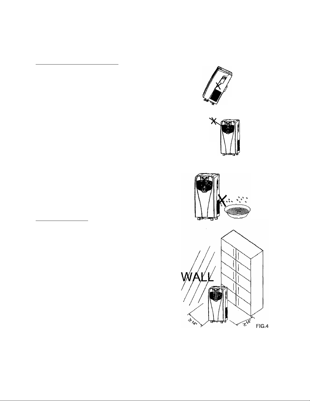
• ALWAYS OPERATE THE UNIT IN AN
UPRIGHT POSITION AND PLACE IT ON
A FLAT. LEVEL SURFACE AT LEAST 14"
(36CM) AWAY FROM ANY OTHER
OBJECTS (FIG 1 & 4).
• DO NOT PLACE OBJECTS ON THE
UNIT, AND DO NOT COVER OR
OBSTRUCT THE INLET OR OUTLET
GRILLES (FIG 2).
■ • THISAPPLIANCE IS NOT INTENDED
FOR USE BY PERSONS (INCLUDING
CHILDREN) WITH REDUCED PHYSICAL,
SENSORY OR MENTAL CAPABILITIES,
OR LACK OF EXPERIENCE AND
KNOWLEDGE. UNLESS THEY HAVE
BEEN GIVEN SUPERVISION OR
INSTRUCTION CONCERNING ITS USE
BY A PERSON RESPONSIBLE FOR
THEIR SAFETY, CHILDREN SHOULD BE
SUPERVISED TO ENSURE THAT THEY
DO NOT PLAY WITH THE APPLIANCE.
FIG. 1
FIG.2
ELECTRICAL SAFETY:
• THIS APPLIANCE IS FOR INDOOR
USE ONLY.
• ALWAYS TURN OFF THE UNIT AND
UNPLUG IT WHEN NOT IN USE.
• DO NOT USE THIS UNIT IN
EXCESSIVELY HUMID OR WET
ENVIRONMENTS (FIG 3).
• DO NOT PULL OR PLACE STRAIN ON
THE POWER CORD WHEN MOVING
THE APPLIANCE.
• IF THE POWER CORD IS DAMAGED,
IT MUST BE REPLACED BY AN
ELECTRICIAN OR SPECIALISED
TECHNICIAN AUTHORIZED BY THE
MANUFACTURER IN ORDER TO
PREVENT FIRE.
FIG.3
Page 3

FOR MAXIMUM EFFICENCY:
For maximum cooling efficiency, make sure
doors and windows are closed while the
portable air conditioner is In use. Also keep
curtains and biinds closed during the
sunniest parts of the day while the air
conditioner is in operation.
Frequently clean the portable air
conditioner’s filters.
Once the room or area has reached your
desired comfort level, be sure to reduce the
unit's temperature and ventilation settings.
Page 4
PARtSiLIST
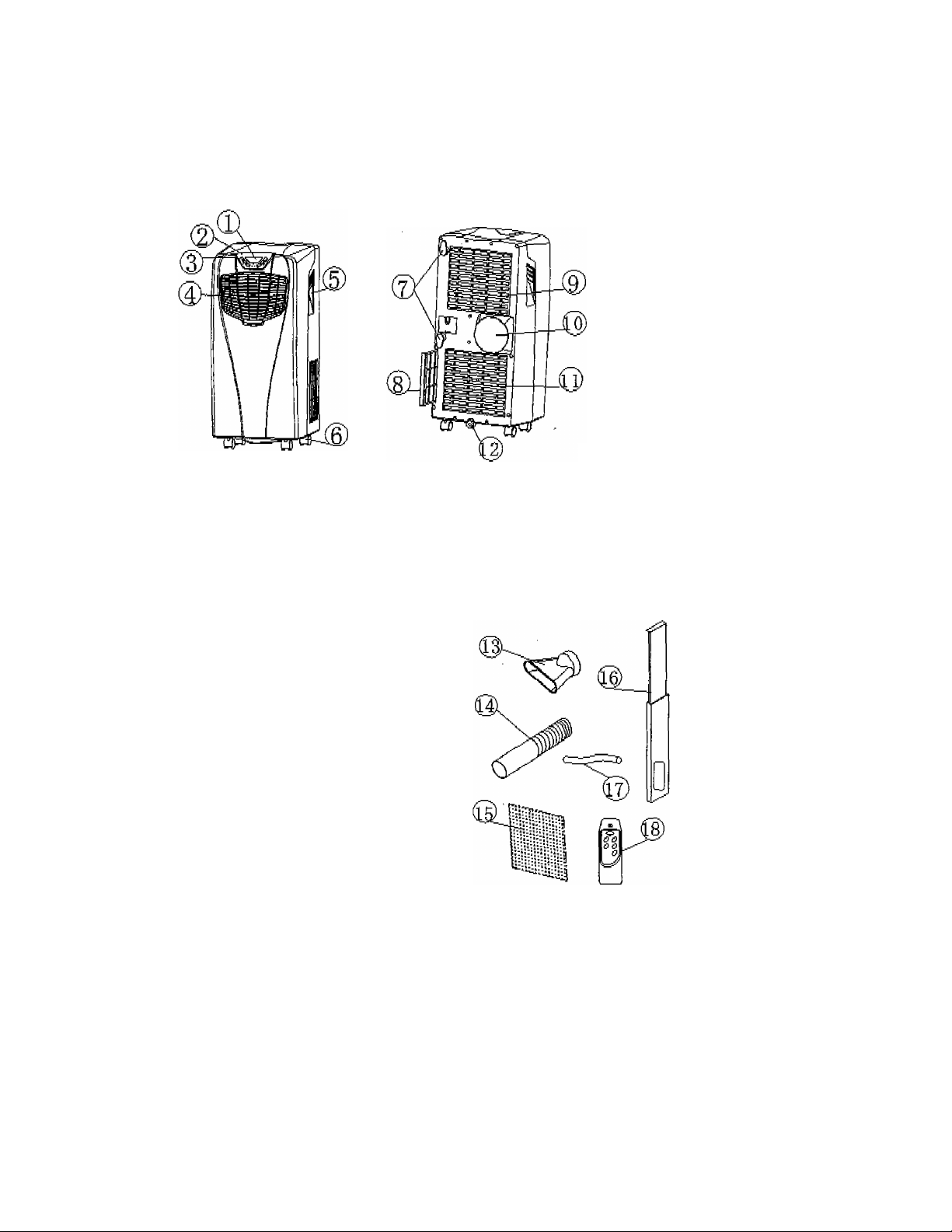
Front
1.
2.
3.
4.
5.
6.
Display window
Control panel
Control buttons
Louvers
Carrying handle
Casters
Back
FIG.6
FIG.5
7. Cord wrap
8. Air filter
9. Air inlet
10. Exhaust air outlet
11. Air inlet
12. Water ptug/drainage port
Accessories
13. Hose adaptor (goes over the
hose and into the window kit)
14. Exhaust hose
15. Activated carbon filter
16. Extendable window kit
17. Hose for continuous drainage
18. Remote control
FIG.7
Page 5
installation instructions
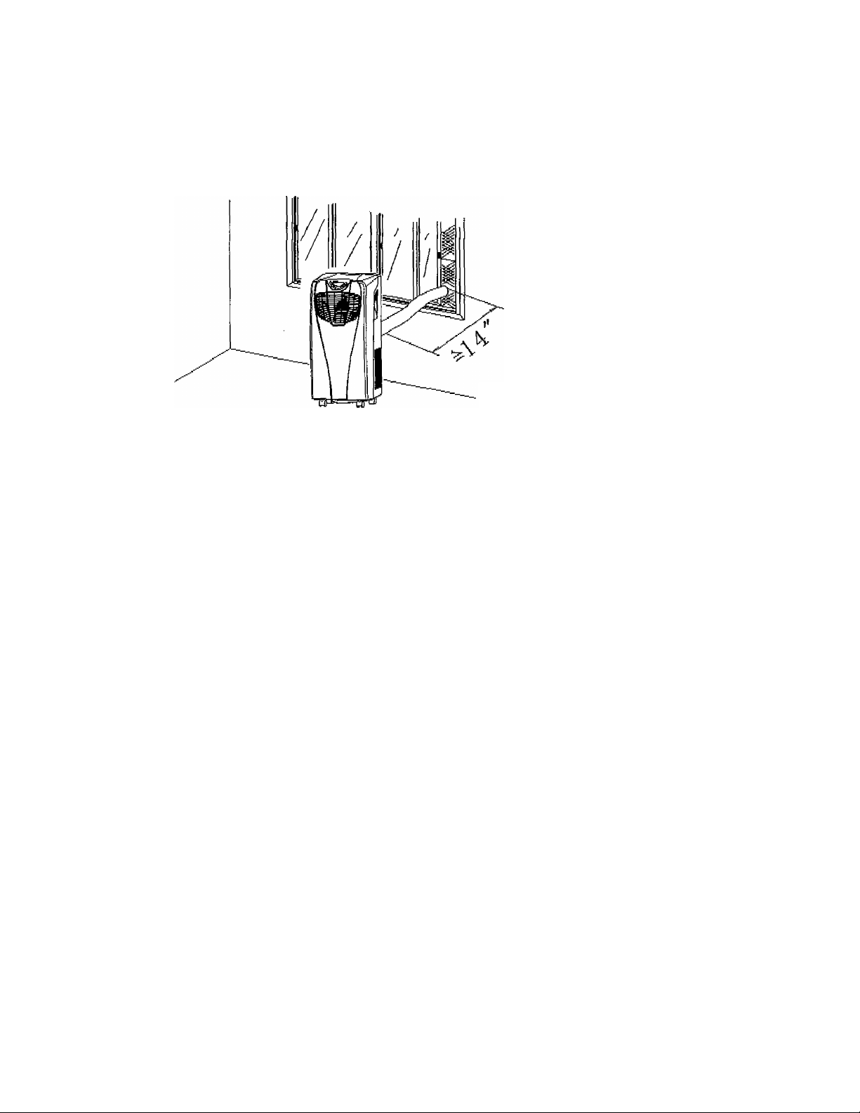
Installing the Exhaust Hose and Window Kit
F1G.6
1. Open the window and insert the window kit into the open gap.
2. Close the window until the window kit is held securely. You may need to adjust the
size of the window kit and secure it with screws. This technique may also be used
for sash windows,
3. Fit the exhaust hose into the exhaust air outlet located on the back of the air
conditioner.
4. Attach the hose adapter onto the exhaust hose.
5. Attach the hose adapter to the window kit.
Page 6

Positioning the Exhaust Hose
• Insert the exhaust hose into
Ч
the back of the unit and tighten
it into place.
• Avoid kinks and bends In the
exhaust hose. These can
cause expelled, moist air to
accumulate, resulting in
overheating and unexpected
shut offs (See Fig 9 & 10).
• The exhaust hose may be
extended from 12 inches (300
mm) to 59 inches (1500 mm),
but for maximum cooling
efficiency, use the shortest
hose length possible.
Fia 9
FIG. 10
WARNING:
The included exhaust hose is
specifically designed to fit the
specifications of this unit. Do not
extend it with your own hose, as
this can cause the air conditioner to
malfunction.
FIG. 11
Page 7

Installing the Activated Carbon Filter
1. . Remove the filter frame from the
unit.
2. Remove the activated carbon filter
from its plastic bag.
3. Insert the activated carbon filter
into the back of the unit.
4. Reattach the filter frame onto the
unit.
FIG.13
Page 8

OPÉRATING INSTRUCTIONS
Control Panel
FIG.14
1.
ON/OFF (power) button
2. Timer button
Timer indicator light
3.
Temperature increase button 12.
4.
Compressor indicator light
5.
Full water tank indicator light
6.
7. Temperature decrease button
Low ventilation indicator light
8.
9.
High ventilation indicator light
10.
Fan mode indicator light
Cooling mode indicator light
11.
Automatic mode indicator light
13. Mode selection button
14.
Fan speed (ventilation) button
15.
Display window
16.
Remote control receiver
Turning the Unit On and Off
1. Press the ON/OFF button. The unit will start automatically. If the ambient
temperature is higher than 74° F, the unit will work in cooling mode, if the
temperature is at or below 74° F, the unit will work in ventilation mode.
2. At this time, the indicator lights showing any functions in progress will turn on.
Please note that the display window will only show ambient room temperatures
ranging from 32° F to 122° F.
3. To turn the unit off. press the ON/OFF button again.
8
Page 9

Setting the Mode/Function
1 * Press the MODE button to select the desired mode (cooling, fan, or automatic).
2. The selected mode's indicator light will turn on.
Setting the Temperature
1. Press the UP or DOWN button to change the set temperature.
2. The display window will then indicate the set temperature. If no temperature is set,
the display will show the room’s ambient temperature.
3. Please note that the preset temperature for cooling is 75° F.
Setting the Fan/Ventilation Speed
1. Press the SPEED button to select the desired fan speed (high or low). The
appropriate indicator light (high or low) will turn on accordingly.
2, If the unit i$ in AUTO mode, the fan speed will be automatically set
according
to the
ambient temperature (the appropriate indicator light will turn on). Please note that
when the unit is in AUTO mode, the speed setting cannot be changed.
Setting the Timer
1. Press the TIMER button to set the desired number of operating hours (from 1 to 12
hours). When the set time has been reached, the machine will automatically turn off.
The display window will show the number of hours being set as you press the
TIMER button. If the TIMER is not set, the unit will work continuously.
2. By pressing the TIMER button without selecting any other modes or settings, you
can set the number
oFhours
to be delayed before the unit
turns on.
For example,
if you press the TIMER to “2", the unit will automatically turn on after 2 hours.
All of the above functions can also be performed
with the included remote control.
The remote control requires 2 AAA batteries to
operate.
FIG. 15 ^
Page 10

Regulating the Air Flow Direction
To control the air flow direction, adjust the knob
on the louvers.
FIG. 16
PLEASE NOTE:
1, To prolong the life of the compressor, after turning off the unit, please wait at least 3
minutes before turning it back on.
2. The cooling system will switch off if the ambient temperature is lower than the set
temperature (the ventilation will keep working at the set level). If the ambient
temperature rises above the selected level, cooling will resume.
10
Page 11

DRAINING THE UNIT
During the cooling process, some water will be extracted from the air and stored within
the unit’s water reservoir.
If the water reservoir is full, both the compressor and motor will stop and the unit will
beep (press any button to stop the beeping sound). The full water tank indicator light
will also start flashing.
To resume cooling, empty the reservoir by following these steps:
Turn off the air conditioner and unplug it
from the wail socket. To prevent water
leakage, avoid moving the unit when full.
2.
Place a container (such as a small pan)
underneath the drainage port.
3. Remove the water plug from the drainage
port and allow the water to drain out.
4. When the container is almost full, replace
the water plug back into the drainage port
and empty the water container.
5. Repeat until the water reservoir is
completely empty.
6. Replace the water plug back into the
drainage port and make sure it is firmly in
place.
7. Turn the unit back on. The warning signal
should turn off.
Water plug
Cap for the
water plug
Drainage port
FIG.17
11
Page 12

For Continuous Drainage
Remove the water plug from the
drainage port ancTretain It for future
use.
Connect the included drainage hose
to the drainage port as shown.
Connect the other end of the hose
into a drain.
The drainage hose may be extended
by adding an extension hose with a
suitable connector.
PLEASE NOTE:
FIG.1S
Water plug
^ Cap for the
water plug
FIG.19
wW Drainage hose
— included with the unit
1. The drain must be at or below the level
Of
the drainage port.
2. The
full
water tank indicator light will not
work when the unit is being
continuously
drained.
3. To extend the drainage hose, you can
connect it with another hose with an
overall diameter of approximately 0.7”
(18 mm).
4. If the room humidity
level
is
over
85%, it
will be necessary to continuously drain
the unit using the drainage hose.
FIG.20
Drainage hose
included with the unit
Extension hose (OD; 0.7”)
12
Page 13

MAINTEN AN<ÌÉ INSTRUQTIQNS
Always unplug the air conditioner from the power supply before cleaning. To maximize the efficiency of the air conditioner, regularly clean the unit.
Cleaning the Housing
• Use a soft, damp cloth to wipe the body clean.
• Never use strong chomicals, gasoline, detergents, chemically-treated cloths, or any
other cleaning solutions to dean the air conditioner, as these can all potentially
damage the unit’s housing.
Cleaning the Filters:
• Use a vacuum cleaner or tap the filter lightly to remove loose dust and dirt from the
filters. Rinse them under running water (no warmer than 1Q4*F),
• Thoroughly dry the filters before replacing them back into the unit.
PLEAE NOTE:
Never operate the unit without the filters.
End of Season Storage
• Completely drain any condensed
water from the unit.
• Set the air conditioner on fan mods
(ventilation only) for a few hours to
dry the inside of the unit.
• Clean or change the filter
• Unplug and wrap the power cord
around the cord wrap as shown (fig,
21).
• Place the unit back in its original
carton and store it in a clean, dry
area.
POWER
CORD
FIG.21
13
Page 14

TftOUB№SHÒ0TlNG
The air conditioner does not work.
The unit does not produce adequate
cooling.
The unit is noisy.
The compressor does not work.
• Is the air conditioner plugged in'?
• is the power outlet functioning correctly?
• Is the full water tank indicator light flashing?
• is the ambient room temperature iower than
• Is the unit placed in direct sunlight? If so,
• Are too many windows or doors open?
• Are there too many people in the room?
• Are there additional heat sources in the
• Is the filter dusty or dirty?
• Is the air inlet or air outlet blocked?
• Is the ambient room temperature lower than
• Is the machine positioned unevenly?
• Is the unit positioned on an even, solid
the set temperature?
close any curtains or move the unit to a
shaded area.
room?
the set temperature?
surface?
Is the compressor's overheat protection
function activated? If so, wait for the
temperature to drop and then turn on the unit
again.
more
Never try to repair or dismantle the unit yourself. Unauthorized repairs can
void your warranty and endanger the user.
14
Page 15

TECHNICAL SPECIFICATIONS
Model Number:
Voltage / Frequency
Power Consumption
AC-10000E
115V/60H^
909W / 8.3A
Air Volume (Maximum Speed) 300 m^/h
Dehumldificatlon Capacity
Compressor Type
2.1 pints/hr(1 l_/hr)
Rotary
Refrigerant Type R-410A
Number of Fan Speeds
Timer
Product Weight
Product Dimensions (W x D x
H)
50 lbs (23 kg)
12 3/16” X 13 13/16” X 27 15/16“
( 310 X 350 X 710 mm )
2
1 ~ 12 hours
ADDITIONAL REMARKS:
Measuring conditions for the above specifications are as follows: DB = 95°F (35"C), WB= 82.94“F
(28.3'' C)
*DB = temperature of dry bulb = room temperature
*WB = temperature of wet bulb - relative humidity.
15
 Loading...