

Page 1

TVG480
JPEG2000 Post Production Gateway
User’s Manual
Revision: 2.8.24 (4422)
2014-06-02
Valid for SW version 2.8.24 and newer
Page 2

Page 3

Contents
1 History 9
2 Introduction 11
2.1 Scope 11
2.2 Warnings, cautions and notes 11
2.3 Heed warnings 12
2.4 Contact information 12
3 Short Product Description 13
3.1 Software options 14
4 Getting Started 15
4.1 Configure the management Ethernet interface 15
4.2 Configure device name and time settings 16
4.3 Select the operational mode 16
4.4 Connect the signals 16
5 Installing the Equipment 19
5.1 Inspect the package content 19
5.2 Installation Environment 19
5.3 Equipment installation 20
5.4 Ventilation 20
5.5 Power supply 21
5.5.1 AC power supply 21
5.5.2 Dual AC power supplies 21
5.5.2.1 AC power cable 21
5.5.2.2 Protective Earth/technical Earth 22
5.5.2.3 Connecting to the AC power supply 22
5.5.3 DC power supply 23
5.5.3.1 DC power cable 23
5.5.4 Powering up/down 23
5.6 Connecting the TVG480 24
5.6.1 Physical description overview 24
5.6.2 SDI ports 24
5.6.3 Ethernet Ports 24
5.6.4 Power Supply 25
5.6.5 Technical Earth 25
5.6.6 Alarm/Reset 26
5.6.7 Serial USB interface 26
6 Operating the Equipment 27
Page 4

6.1 Accessing the graphical user interface 27
6.2 Password protection 27
6.2.1 Resetting the password list 28
6.3 Changing the IP address of the unit 28
6.3.1 Changing IP address via the Web GUI 28
6.3.2 Changing the management port IP address via the terminal interface 30
6.3.3 Configuring automatic IP address assignment 30
6.4 Stereoscopic 3D operation 31
6.4.1 Requirements 31
6.4.2 Configuration 32
6.5 Hitless switching 32
7 WEB Interface 35
7.1 Login 35
7.2 Status header 36
7.3 WEB pages overview 37
7.3.1 Status 37
7.3.2 Device info 37
7.3.3 Encoders 38
7.3.4 Decoders 38
7.3.5 SDI Ports 38
7.3.6 IP Status 39
7.4 Status 39
7.4.1 Current Status 39
7.4.2 Alarm log 41
7.5 Device Info 42
7.5.1 Product info 43
7.5.2 Alarms 45
7.5.2.1 Device alarms 46
7.5.2.2 Global configuration 46
7.5.2.3 Relays and LED 47
7.5.2.4 Alarm log settings 49
7.5.3 Time Settings 50
7.5.4 Reference Sync 53
7.5.4.1 IP RX Video RefSync 53
7.5.4.2 Alarms 54
7.5.5 Network 54
7.5.5.1 Interfaces 55
7.5.5.1.1 Main 55
7.5.5.1.2 Interface Settings 56
7.5.5.1.3 DHCP Settings 56
7.5.5.1.4 DHCP Status 57
7.5.5.1.5 Manual IP Settings 58
7.5.5.1.6 Interface Status 58
7.5.5.1.7 Detect Settings 59
7.5.5.1.8 Alarms 59
Page 5

7.5.5.1.9 Advanced 59
7.5.5.1.10 Status 60
7.5.5.1.11 VLAN 62
7.5.5.1.12 Main Settings 62
7.5.5.1.13 Manual IP Settings 63
7.5.5.1.14 Advanced Settings 63
7.5.5.1.15 DHCP settings and status 63
7.5.5.1.16 SFP 63
7.5.5.2 DNS Settings 72
7.5.5.3 IP Routing 72
7.5.5.4 TXP Settings 73
7.5.5.5 SNMP Settings 74
7.5.5.6 Tools 75
7.5.5.6.1 Ping 76
7.5.5.6.2 Traceroute 77
7.5.6 Save/Load Config 78
7.5.6.1 Save/Load Configs 79
7.5.6.1.1 Save Configuration 79
7.5.6.1.2 Load Configuration From file 80
7.5.6.1.3 Load Configuration from Remote Device 80
7.5.6.1.4 Load options 81
7.5.6.2 Boot Log 81
7.5.6.3 Stored Configs 82
7.5.6.4 Emergency Switch 83
7.5.7 Maintenance 86
7.5.7.1 General 86
7.5.7.2 Software Upgrade 87
7.5.7.3 Feature Upgrade 89
7.5.8 Users 89
7.5.9 GUI Preferences 90
7.6 Encoders 91
7.6.1 Encoders overview 91
7.6.2 Encoder 92
7.6.2.1 Main 92
7.6.2.2 Alarms 95
7.6.2.3 JPEG2000 95
7.6.2.4 Audio 96
7.6.2.5 HD VBI 97
7.6.2.6 ANC 97
7.6.2.7 Advanced 98
7.6.3 Encoder, Source 99
7.6.3.1 Main 99
7.6.3.2 Alarms 100
7.6.4 Encoder, IP Destination 101
7.6.4.1 Main 101
7.6.4.2 FEC 103
7.6.4.3 Ping 104
Page 6

7.7 Decoders 105
7.7.1 Decoders overview 105
7.7.2 Decoder 106
7.7.2.1 Main 106
7.7.2.2 Alarms 108
7.7.2.3 JPEG2000 108
7.7.2.4 Audio 110
7.7.2.5 HD VBI 110
7.7.2.6 ANC 111
7.7.2.7 Advanced 111
7.7.3 Decoder, Source 113
7.7.3.1 Main 113
7.7.3.2 Alarms 114
7.7.3.3 FEC 115
7.7.3.4 Ping 115
7.7.3.5 Stat 115
7.7.4 Decoder, IP Diversity RX 115
7.7.5 Decoder, SDI Out 117
7.7.5.1 Main 117
7.7.5.2 Decoder SDI Out Alarms page 117
7.8 SDI Ports 117
7.8.1 Main 117
7.8.1.1 SDI-IN 118
7.8.1.2 SDI-OUT 119
7.8.1.3 Alarms 119
7.9 IP Status 120
8 SNMP 121
8.1 SNMP agent characteristics 121
8.2 MIB naming conventions 121
8.3 MIB overview 121
8.3.1 Supported standard MIBs 121
8.3.2 Custom MIBs 121
8.4 SNMP related configuration settings 123
8.4.1 Community strings 124
8.4.2 Trap destination table 124
8.4.3 Trap configuration 124
8.5 Alarm/status related SNMP TRAPs 125
8.5.1 The main trap messages 125
8.5.2 Severity indications 125
8.5.3 Alarm event fields 126
8.5.4 Matching of on/off traps 127
8.5.5 Legacy trap messages 127
8.6 Using net-snmp to access MIB information 128
8.6.1 Reading a parameter with snmpget 128
8.6.2 Writing a parameter with snmpset 128
Page 7

9 Preventive Maintenance and Fault-finding 131
9.1 Preventive maintenance 131
9.1.1 Routine inspection 131
9.1.2 Cleaning 131
9.1.3 Servicing 131
9.1.4 Warranty 132
9.2 Fault-finding 132
9.2.1 Preliminary checks 132
9.2.2 PSU LED not lit / power supply problem 133
9.2.3 Fan(s) not working / unit overheating 134
9.3 Disposing of this equipment 134
9.4 Returning the unit 134
A Glossary 135
B Technical Specification 141
B.1 Physical details 141
B.1.1 Half-width version 141
B.1.2 Full-width (dual power) version 141
B.2 Environmental conditions 141
B.3 Power 142
B.3.1 AC Mains supply 142
B.3.2 DC supply 142
B.4 Input/output ports 142
B.4.1 HD-SDI port 142
B.4.2 Ethernet ports 143
B.4.3 Serial USB interface 143
B.5 Alarm ports 143
B.5.1 Alarm relay/reset port specification 143
B.6 Compliance 144
B.6.1 Safety 144
B.6.2 Electromagnetic compatibility - EMC 144
B.6.3 CE marking 145
B.6.4 Interface to “public telecommunication system” 145
C Forward Error Correction in IP Networks 147
C.1 IP stream distortion 147
C.2 Standardisation 148
C.3 FEC matrix 148
C.4 Transmission aspects 151
C.5 Quality of service and packet loss in IP networks 152
C.6 Error improvement 153
C.7 Latency and overhead 154
Page 8

D Quality of Service, Setting Packet Priority 157
D.1 MPLS 157
D.2 Layer 3 routing 157
D.2.1 TVG480 configuration 158
D.3 Layer 2 priority 158
D.3.1 TVG480 configuration 158
E Alarms 159
F References 169
Page 9

1 History
Revision Date SW version Comments
2.8.24 June 2014 2.8.24 Updated for sw version 2.8.24
2.6.8 April 2013 2.6.8 Updated for sw version 2.6.8
2.4.4 March 2012 2.4.4 Updated for sw version 2.4.4
2.2.8 January 2012 2.2.8 Updated for sw version 2.2.8
2.0.20 August 2011 2.0.20 Updated for sw version 2.0.20
1.2.22 December 2010 1.2.22 Updated for sw version 1.2.22
1.0.0 October 2009 1.0.0 Initial release
History 9
ID: um_jpeg2000postproductiongateway TVG480 User’s Manual Rev. 2.8.24 (4422)
Page 10

10
TVG480 User’s Manual Rev. 2.8.24 (4422) ID: um_jpeg2000postproductiongateway
Page 11

Introduction 11
2 Introduction
2.1 Scope
This manual is written for operators and users of the TVG480 JPEG2000 Post Production Gateway and provides necessary information for installation, operation and day-to-day maintenance
of the unit. The manual covers the functionality of the software version 2.8.24 or later, and continues to be relevant to subsequent software versions where the functionality of the equipment
has not been changed. When a new software version changes the functionality of the product,
an updated version of this manual will be provided.
The manual covers the following topics:
• Getting started
• Equipment installation
• Operating instructions
• WEB interface description
• Preventive maintenance and fault finding
• Alarm listing
• Technical specifications
2.2 Warnings, cautions and notes
Throughout this manual warnings, cautions and notes are highlighted as shown below:
Warning: This is a warning. Warnings give information, which if strictly
observed, will prevent personal injury and death, or damage to personal
property or the environment.
Caution: This is a caution. Cautions give information, which if strictly
followed, will prevent damage to equipment or other goods.
Note: Notes provide supplementary information. They are highlighted for
emphasis, as in this example, and are placed immediately after the relevant
text.
ID: um_jpeg2000postproductiongateway TVG480 User’s Manual Rev. 2.8.24 (4422)
Page 12

12 Introduction
2.3 Heed warnings
• All warnings marked on the product and in this manual should be adhered to. The
manufacturer cannot be held responsible for injury or damage resulting from negligence of warnings and cautions given.
• All the safety and operating instructions should be read before this product is installed and operated.
• All operating and usage instructions should be followed.
• The safety and operating instructions should be retained for future reference.
2.4 Contact information
Our primary goal is to provide first class customer care tailored to your specific business and
operational requirements.
Please contact us at:
Telephone +47 22 88 97 50
Fax +47 22 88 97 51
E-mail support@t-vips.com
WEB www.t-vips.com
Mail and visiting address T-VIPS AS
Nils Hansens vei 2
NO-0667 Oslo
Norway
TVG480 User’s Manual Rev. 2.8.24 (4422) ID: um_jpeg2000postproductiongateway
Page 13

Short Product Description 13
3 Short Product Description
The TVG480 JPEG2000 Post Production Gateway represents the next generation solution for
transport of high definition TV over IP networks.
The TVG480 JPEG2000 Post Production Gateway is a member of the T-VIPS Video Gateway suite;
a line of compact, powerful and cost-effective products designed for real-time contribution and
distribution of broadcast quality video over IP networks.
The TVG480 JPEG2000 Post Production Gateway provides encoding or decoding of up to two
HD-SDI channels simultaneously.
TVG480 JPEG2000 Post Production Gateway takes advantage of the unmatched quality of JPEG2000
compression combined with the inherent flexibility of IP. JPEG2000 wavelet compression technology enables transmission of compressed 3G HD, HDTV and SD television over Gigabit Ethernet. Broadcasters are offered an efficient, affordable and scalable solution for studio quality,
high definition, video contribution.
TVG480 enables operators to utilize Ethernet technology to build cost effective SONET, IPMPLS or Metro Ethernet networks for video transport. Built in Quality of Service functionality
combined with Forward Error Correction and error concealment secures flawless operation from
end to end even in presence of IP impairments as packet loss or heavy jitter.
Salient features of the TVG480 are:
• Up to two JPEG2000 compressed simultaneous HD-SDI video channels, depending on
licensed features.
• High Quality Video
− Programmable JPEG2000 compression
− 10 bit video resolution
− Frame-by-frame encoding
• Robust transmission of HD-SDI signals
− Flexible Forward Error Correction (option)
− Error concealment
− Ethernet interfaces, electrical or SFP
− Smallcast
− Hitless switching (using RTP/IP diversity reception (option))
• Very Low Delay
− Aggregate encoding and decoding delay less than 60 ms (mode dependent)
ID: um_jpeg2000postproductiongateway TVG480 User’s Manual Rev. 2.8.24 (4422)
Page 14

14 Short Product Description
• MXF encapsulation
− Suitable for file-based workflow
• Ancillary data support
− Transparent transfer of embedded audio and vertical interval data
• Compact, flexible cost-effective solutions
− Half-width 19 inch 1 RU version, sideways stackable
− Full-width 19 inch 1 RU version with dual power.
• User-friendly configuration and control
− WEB/XML based remote control
− SNMP agent for easy integration with network management systems (NMS)
− Can be integrated with T-VIPS Connect
3.1 Software options
The TVG480 JPEG2000 Post Production Gateway functionality depends on software modules
that may be individually enabled through a software licensing scheme. Software licences may
be purchased from T-VIPS and installed by the user.
The following table describes features available as software options. Please refer to
for more information about how to enable new software features.
Table 3.1 Functionality enabled through software licences
Functionality Function
Connect Control Supervision of the unit through the Connect software. This must be enabled in order to
allow remote supervision.
Forward Error Correction Pro-MPEG Forward Error Correction.
Encoding Enables encoding functionality.
Decoding Enables decoding functionality.
SFP Module Enables use of the SFP module.
Allow Stereo 3D operation Enables encoding/decoding of stereoscopic 3D signals.
RTP/IP Diversity Reception Enables hitless switching between two identical IP input streams
The feature list for the TVG480 JPEG2000 Post Production Gateway will show more features
than listed here. For available upgrade options, please contact sales@t-vips.com.
Chapter 7
TVG480 User’s Manual Rev. 2.8.24 (4422) ID: um_jpeg2000postproductiongateway
Page 15

Getting Started 15
4 Getting Started
This section provides a short description of the minimum steps that must be taken in order to
start operating the TVG480.
If you are an experienced user of T-VIPS equipment or similar types of encoding/decoding
equipment the following description should enable you to quickly install the TVG480 JPEG2000
Post Production Gateway and start operation. If this is your first time to install such equipment
you are strongly adviced to read the full installation procedure. To gain full benefit of the
product functionality and capabilities refer to the user interface description.
The procedures outlined below are based on the assumption that the unit is in the factory
default state.
4.1 Configure the management Ethernet interface
Since the primary interface for controlling the TVG480 is Web based, the first step is to set up
the IP address for the management interface.
Changing the default IP address using the Web interface requires that your management computer may be configured with a static IP address. If a static IP address cannot be configured on
your computer the IP address may be configured via the terminal interface. The procedure is
described in the user manual.
Note: Avoid connecting through a network at this stage, as this may give
unpredictable results due to possible IP address conflict.
1. Connect an Ethernet cable directly between the PC and the Ethernet 1 port of the
TVG480. The default IP address of the TVG480 is 10.0.0.10/255.255.255.0. Configure the
PC to be on the same subnet as the TVG480.
2. Open your Web browser and type http://10.0.0.10 in the address field of the browser.
Log into the GUI with username admin and password salvador.
3. Browse to Device Info > Network > Ethernet 1 in the GUI, and set the IP address
settings required for your network. Click Apply to activate the new parameters.
4. The connection with your management PC will now be lost. To re-connect to the
TVG480 connect both the Ethernet 1 port of the unit and the management PC to the
network. The IP settings of the management PC must now be set to agree with the
network used.
5. Again, open your Web browser and type http: (New-IP-Address) in the address field of
the browser. Log into the GUI with username admin and password salvador.
An alternative to using the WEB browser to configure the IP address is to set up the address
using a local USB cable. This procedure is explained in Section 6.3.2.
ID: um_jpeg2000postproductiongateway TVG480 User’s Manual Rev. 2.8.24 (4422)
Page 16

16 Getting Started
4.2 Configure device name and time settings
1. Assign a name for the device in order to more easily identify the unit in the network.
Browse to Device Info > Product Info and enter a Name and Inventory ID. Click Apply
to activate.
2. Set date and time of the real time clock to ensure correct time stamping of the alarm
log entries. Browse to Device Info > Time Settings. The internal clock may be used to
time stamp alarm log entries, in which case a manual Date and Time adjust is all that
is needed. Click Apply to activate.
You may enable an external time source to provide a common reference for alarm logs
of all units of a system. Refer to the user manual for details.
4.3 Select the operational mode
Before starting to use the TVG480, it is essential to understand the fundamental operational
modes of the unit.
Note: Changing the operational mode requires reboot of the unit.
For the TVG480, there are three fundamental operational modes that need to be configured.
These are listed in the following table.
The operational modes are configured on the Device Info > Maintenance subpage as shown in
Figure 4.1.
To change an operational mode, select the new mode from the drop down lists/radio buttons.
When pressing the Apply button, you are asked to confirm reboot of the device. By accepting
the request, the unit will reboot and the device will start up in the new configured mode.
4.4 Connect the signals
After configuring the IP address and operational mode, the product is ready to do encoding or
decoding of video signals. To configure parameters needed for encoding, see Section 7.6. To
configure parameters needed for decoding, see Section 7.7.
TVG480 User’s Manual Rev. 2.8.24 (4422) ID: um_jpeg2000postproductiongateway
Page 17

Getting Started 17
Operational mode Description Values
Encode/Decode This mode selects whether the device shall operate as
a pure encoder, a pure decoder or a combined
encoder/decoder (“bidirectional mode”).
Ethernet Interface The TVG480 in standard configuration has three
network ports, but only two of them can be used
simultaneously. Depending on the operational mode,
it can operate with either two electrical Gigabit
Ethernet ports, or one SFP and one electrical Gigabit
Ethernet.
As a HW-option, the TVG480 can be delivered with
two additional network ports, one electrical and one
SFP. Except for Ethernet port 1 (electrical Gigabit),
which is always available, only ports of the same type,
electrical or SFP, can be used simultaneously.
Depending on the operational mode, it can thus
operate with either three electrical Gigabit Ethernet
ports, or one electrical Gigabit Ethernet port and two
SFP ports.
Video Field Rate Selects the fundamental video field rate of the unit.
It must be set to match the video formats that will
be used during operation.
Encode, Decode or Encode/Decode
SFP, 1000Base-T
50Hz/24Hz, 59.94Hz/23.98Hz and 60Hz
Figure 4.1 Operational modes for the TVG480
ID: um_jpeg2000postproductiongateway TVG480 User’s Manual Rev. 2.8.24 (4422)
Page 18

18
TVG480 User’s Manual Rev. 2.8.24 (4422) ID: um_jpeg2000postproductiongateway
Page 19

Installing the Equipment 19
5 Installing the Equipment
Caution: The TVG480 must be handled carefully to prevent safety hazards
and equipment damage. Ensure that the personnel designated to install
the unit have the required skill and knowledge. Follow the instructions
for installation and use only installation accessories recommended by the
manufacturers.
5.1 Inspect the package content
• Inspect the shipping container for damage. Keep the shipping container and cushioning
material until you have inspected the contents of the shipment for completeness and
have checked that the TVG480 is mechanically and electrically in order.
• Verify that you received the following items:
− TVG480 with correct power supply option
− Power cord(s)
− CD-ROM containing documentation and Flash Player installation files
− Any optional accessories you have ordered
Note: 48 VDC versions do not ship with a power cord; instead a Power
D-SUB male connector for soldering to the supply leads is supplied.
5.2 Installation Environment
As with any electronic device, the TVG480 should be placed where it will not be subjected to
extreme temperatures, humidity, or electromagnetic interference. Specifically, the selected site
should meet the following requirements:
• The ambient temperature should be between 0 and 50◦C (32 and 122◦F).
• The relative humidity should be less than 95 %, non-condensing. Do not install the
unit in areas of high humidity or where there is danger of water ingress.
• Surrounding electric devices should comply with the electromagnetic field (EMC) standard IEC 801-3, Level 2 (less than 3 V/m field strength).
• The AC power outlet (when applicable) should be within 1.8 meters (6 feet) of the
TVG480.
ID: um_jpeg2000postproductiongateway TVG480 User’s Manual Rev. 2.8.24 (4422)
Page 20

20 Installing the Equipment
• Where appropriate, ensure that this product has an adequate level of lightning protection. Alternatively, during a lightning storm or if it is left unused and unattended for
long periods of time, unplug it from the power supply and disconnect signal cables.
This prevents damage to the product due to lightning and power-line surges.
Warning: If the TVG480 has been subject to a lightning strike or a power
surge which has stopped it working, disconnect the power immediately.
Do not re-apply power until it has been checked for safety. If in doubt
contact T-VIPS.
5.3 Equipment installation
The TVG480 is designed for stationary use in a standard 19" rack. When installing please observe
the following points:
• Route cables safely to avoid them being pinched, crushed or otherwise interfered with.
Do not run AC power cables and signal cables in the same duct or conduit.
• The TVG480 has all connectors at the rear. When mounting the unit, ensure that the
installation allows easy access to the rear of the unit.
• The fans contained in this unit are not fitted with dust/insect filters. Pay particular
attention to this when considering the environment in which it shall be used.
• Make sure that the equipment is adequately ventilated. Do not block the ventilation
holes on each side of the TVG480.
5.4 Ventilation
Openings in the cabinet are provided for ventilation to protect it from overheating and ensure
reliable operation. The openings must not be blocked or covered. Allow at least 50 mm free
air-space each side of the unit.
Warning: Never insert objects of any kind into this equipment through
openings as they may touch dangerous voltage points or create shorts that
could result in a fire or electric shock. Never spill liquid of any kind on or
into the product.
• This product should never be placed near or over a radiator or heat register. Do not
place in a built-in installation (e.g. a rack) unless proper ventilation is provided in
accordance with the device airflow design as depicted in Figure 5.1.
• The TVG480 may be vertically stacked in 19" racks without intermediate ventilation
panels. In systems with stacked units forced-air cooling may be required to reduce the
operating ambient temperature.
Figure 5.1 shows the air path through the unit, where cool air is taken from the left
hand side, seen from the front.
TVG480 User’s Manual Rev. 2.8.24 (4422) ID: um_jpeg2000postproductiongateway
Page 21

Installing the Equipment 21
CP541
Cool
Air In
Warm
Air Out
Figure 5.1 Air path through the unit
5.5 Power supply
The TVG480 may be delivered rated for AC or DC operation, respectively.
Warning: This product should be operated only from the type of power
source indicated on the marking label. Please consult a qualified electrical
engineer or your local power company if you are not sure of the power
supplied at your premises.
5.5.1 AC power supply
The TVG480 has a wide-range power supply accepting the voltage range 100-240 VAC, 50/60
Hz. Please refer to Appendix B for a detailed specification of the AC power supply.
5.5.2 Dual AC power supplies
Alternatively, the TVG480 may be fitted with dual internal wide-range AC power supplies. If so,
the size of the cabinet is full-width 19" rack, 1RU. The power supplies cover the voltage range
100-240 VAC, 50/60 Hz.
During normal operation, load-sharing is used between the internal supplies. In case of a single
power supply failure alarms will be raised and the unit will continue operating off the second
power supply. To guard against failure in the external power circuitry it is imperative to connect
each power supply to separate AC mains circuits.
Please refer to
Appendix B for a detailed specification of the AC power supply.
5.5.2.1 AC power cable
Ensure that the AC power cable is suitable for the country in which the unit is to be operated.
Caution: Power supply cords should be routed so that they are not likely
to be trod on or pinched by items placed upon or against them. Pay
particular attention to cords at plugs and convenience receptacles.
The unit is supplied with a two meter detachable mains supply cable equipped with a moulded
plug suitable for Europe, UK or USA, as appropriate. The wires in the mains cable are coloured
in accordance with the wire colour code shown in Table 5.1.
ID: um_jpeg2000postproductiongateway TVG480 User’s Manual Rev. 2.8.24 (4422)
Page 22

22 Installing the Equipment
Table 5.1 Supply cable wiring colours
Wire UK (BS 1363) EUROPE (CEE 7/7) USA (NEMA 5-15P)
Earth Green-and yellow Green-and yellow Green
Neutral Blue Blue White
Live Brown Brown Black
5.5.2.2 Protective Earth/technical Earth
To achieve protection against earth faults in the installation introduced by connecting signal
cables etc., the equipment should always be connected to protective earth. If the mains supply
cable is disconnected while signal cables are connected to the equipment, an earth connection
should be ensured using the Technical Earth connection terminal on the rear panel of the unit.
Warning: This unit must be correctly earthed through the moulded plug
supplied. If the local mains supply does not provide an earth connection
do not connect the unit.
Caution: Consult the supply requirements in Appendix B prior to connecting the unit to the supply.
The unit has a Technical Earth terminal located in the rear panel. Its use is recommended. This
is not a protective earth for electrical shock protection; the terminal is provided in order to:
1. Ensure that all equipment chassis fixed in the rack are at the same technical earth
potential. To achieve this, connect a wire between the Technical Earth terminal and a
suitable point in the rack. To be effective all interconnected units should be earthed
this way.
2. Eliminate the migration of stray charges when interconnecting equipment.
Warning: If the terminal screw has to be replaced, use an M4x12mm long
pozidrive pan head. Using a longer screw may imply a safety hazard.
5.5.2.3 Connecting to the AC power supply
Warning: Do not overload wall outlets and extension cords as this can
result in fire hazard or electrical shock. The unit is not equipped with an
on/off switch. Ensure that the outlet socket is installed near the equipment
so that it is easily accessible. Failure to isolate the equipment properly may
cause a safety hazard.
TVG480 User’s Manual Rev. 2.8.24 (4422) ID: um_jpeg2000postproductiongateway
Page 23

Installing the Equipment 23
To connect the unit to the local AC power supply, connect the AC power lead to the TVG480
mains input connector(s) and then to the local mains supply.
5.5.3 DC power supply
The TVG480 can be delivered with a 48 VDC power supply for use in environments where this
is required. The DC power supply accepts an input voltage range of 36-72 VDC. Please refer to
Appendix B for detailed specification of the power supply.
5.5.3.1 DC power cable
Units delivered with DC power supply have a 3-pin male D-SUB power connector instead of
the standard mains power connector. Also a female 3-pin D-SUB connector is supplied. The
pin assignment is shown in Table 5.2. The power cable itself is not supplied.
Table 5.2 DC power connector pin
assignment
Pin Placement Specification
1 top + (positive terminal)
2 middle - (negative terminal)
3 bottom Chassis Ground
To connect the unit to the local DC power supply:
1. Use an electronics soldering iron or a hot air workstation to attach the supplied female
D-SUB power connector to suitable power leads.
2. Connect the power leads to your local power supply.
3. Connect the DC power connector, with attached power leads, to the TVG480 power
input connector.
5.5.4 Powering up/down
Before powering-up the unit, please ensure that:
• The unit is installed in a suitable location
• The unit has been connected to external equipment as required
Power up the unit by inserting the power cable connected to the power source. When the unit
has finished the start-up procedure, the fans will run at normal speed. Please check that all
cooling fans are rotating. If they are not, power down the unit immediately.
Power down the unit by removing the power supply connector at the rear of the unit.
ID: um_jpeg2000postproductiongateway TVG480 User’s Manual Rev. 2.8.24 (4422)
Page 24

24 Installing the Equipment
5.6 Connecting the TVG480
5.6.1 Physical description overview
The front panel provides two LEDs per TVG480. The meaning of each LED indicator is shown
in Table 5.3.
Table 5.3 Front panel LED descriptions
Indicator Colour Description
PSU Green
Alarm Red This LED is lit when a failure is detected by the unit
These LEDs are also replicated on the rear panel, shown in Figure 5.2.
Normal operation
Unlit
During system boot
Figure 5.2 Rear panel
Disconnect mains supply before moving or installing the equipment. Ensure ESD precautions
are observed while interconnecting equipment.
5.6.2 SDI ports
The TVG480 has 2 HD-SDI input ports and 4 HD-SDI output ports. The ports are physically
capable of both HD-SDI and 3G-SDI.
Note: Input ports 3 and 4 are not used for the TVG480.
5.6.3 Ethernet Ports
The TVG480 in standard configuration provides three Ethernet ports, of which two can be used
simultaneously. Ethernet 1 is always active, together with either Ethernet 2 or SFP (Small FormFactor Pluggable). (Switching between the modes is done by changing the operational mode
parameter described in Section 4.3).
The default interface speed mode for the electrical Ethernet ports is 1000Base-T. In this mode
the port can auto sense between 10, 100 and 1000 Mbit/s. The operator is able to force the
TVG480 User’s Manual Rev. 2.8.24 (4422) ID: um_jpeg2000postproductiongateway
Page 25

Installing the Equipment 25
interface speed to various fixed speeds. This is normally not necessary, but may be useful for
minimizing the synchronisation time when reconnecting signal cables.
For flexibility, the TVG480 provides a Small Form-Factor Pluggable (SFP) slot to carry a copper or
optical SFP, allowing customers to use different SFPs for special distance, cost, existing infrastructure, and future expansion requirements. The TVG480 is prepared for electrical (1000Base-T) or
optical 1000BASE-SX and 1000BASE-LX SFP transceivers.
The LEDs for the electrical Ethernet ports are used as follows:
Table 5.4 Electrical
Ethernet port LEDs
LED indicator Location Description Colour
Activity Left 10 Mbit/s
100 Mbit/s
1000 Mbit/s
Link Right Lit=Link Green
In an extended configuration, two additional Ethernet ports are provided, one electrical (Ethernet
3) and one SFP (SFP 2). These have the same specifications as the standard Ethernet ports, and
their usage is restricted so that each one is only active together with the ports Ethernet 2 or SFP,
respectively.
Green
Yellow
Orange
The rear panel when configured with these additional Ethernet ports is shown in Figure 5.3.
Figure 5.3 Rear panel in extended configuration
5.6.4 Power Supply
Section 5.5 provides details of the power supply, protective earth and security. Read all these
instructions prior to connecting the unit’s power cable.
5.6.5 Technical Earth
Connect the Technical Earth to a suitable earth point.
ID: um_jpeg2000postproductiongateway TVG480 User’s Manual Rev. 2.8.24 (4422)
Page 26

26 Installing the Equipment
5.6.6 Alarm/Reset
The unit is equipped with a 9-pin male DSub connector to provide alarm information. The
connector is labelled Alarm on the back panel.
Two programmable relays are provided. The first relay is always activated on a critical alarm or
when the unit is not powered. Please refer to
the relays.
The pin out of the connector is shown in Table 5.5.
Table 5.5 Alarm/Reset
connector pin out
Pin Function
1. Relay 2 - Closed on alarm (NC)
2. Relay 2 Common
3. Relay 2 - Open on alarm (NO)
4. Prepared for +5V Output
5. Ground
6. Relay 1 - Closed on alarm (NC)
7. Relay 1 Common
8. Relay 1 - Open on alarm (NO)
9. Optional Reset Input / GPI
Section 7.5.2.3 for a description how to program
When there is a critical (level 6) alarm in the unit, if the unit has no power or any other
programmed condition for relay 1 is satisfied, there will be a connection between pin 6 and pin
7. Otherwise, there will be a connection between pin 7 and pin 8.
The optional (additional) relay will follow the same behaviour, except that it can also be programmed not to be activated for a critical (level 6) alarm.
A connection between pins 9 and 5 (or a TTL low on pin 9) will hold the unit reset, provided
this function has been enabled. The connection must be held for more than 0.5 seconds in order
to activate the reset. This can be used to force a hard reset of the unit from an external control
system. This pin can also be used as a general purpose input (GPI).
For more details regarding the alarm relay, please refer to Technical Specifications,
Appendix
B.
5.6.7 Serial USB interface
The TVG480 is also provided with a USB interface to communicate with the administrator PC.
USB 1.1 is supported and the physical interface is a mini USB connector.
The USB interface requires a special COM port driver in the PC that shall communicate with the
device. This driver is provided on the product CD shipped with the device. The USB interface
is intended for initial IP address setup.
TVG480 User’s Manual Rev. 2.8.24 (4422) ID: um_jpeg2000postproductiongateway
Page 27

Operating the Equipment 27
6 Operating the Equipment
The TVG480 is configured and controlled locally and remotely through a Flash-based Web
interface. The only application required on the computer to use this interface is a Web browser
and the Adobe Flash Player.
Note: Adobe Flash Player 9.0 or newer is required to use the Web interface
of the TVG480. As a general rule it is recommended to always use the
latest official release of Flash Player (version 10 or newer). If the Flash
Player is not installed on the adminstrator PC, a copy is provided on the CD delivered
with the device. Alternatively, the latest Adobe Flash Player can be downloaded
free of charge from
Note: When using Microsoft Internet Explorer, version 6.0 or higher is
required. It is however recommended to upgrade to version 8.0 or newer
for best performance.
http://www.adobe.com.
6.1 Accessing the graphical user interface
The default IP address of the TVG480 will most probably not be suitable for the network where
the unit will operate. Initially therefore, the user should change the IP address of the management interface so that access may be gained from the network.
The TVG480 offers two options to alter the user interface IP address; through an Ethernet
connection or using a USB terminal interface. If your management computer allows setting a
fixed IP address, change the IP address using the Ethernet option described in Section 6.3.1.
If a static address cannot be configured on your management computer, Section 6.3.2 gives the
procedure to initially configure device network parameters (IP, netmask, etc...) using the USB
terminal interface.
Configuring the device functionality according to operational needs is done using the Web
interface, see Chapter 7.
6.2 Password protection
Remote access to the device is controlled by password protection. If you access the TVG480
using the USB terminal interface a password is not required.
There are 3 user levels providing different user privileges, each with a separate default password:
Username Default password Privileges
admin salvador Full access to device
operator natal Configure setting, cannot alter passwords
guest guest View configuration and alarm logs
ID: um_jpeg2000postproductiongateway TVG480 User’s Manual Rev. 2.8.24 (4422)
Page 28

28 Operating the Equipment
The passwords can later be changed, either from the Web GUI or via the terminal.
6.2.1 Resetting the password list
If a password is lost, the password list can be reset to factory defaults via the local USB terminal
interface. To reset the password list, type the following command in the terminal interface:
userdb factory_defaults
Note: The factory_defaults option on the userdb command is avail-
able without administrator previledges only when accessing the terminal
via the local USB interface. In remote terminal sessions with a Telnet
client, administrator privileges are required to run the same command.
6.3 Changing the IP address of the unit
The default IP configuration on the Ethernet ports is described in Table 6.1.
Table 6.1 Default
IP configuration
Interface IP address Subnet mask
Ethernet 1 10.0.0.10 255.255.255.0
Ethernet 2 169.254.1.11 255.255.255.0
SFP 169.254.2.12 255.255.255.0
Ethernet 3 169.254.3.13 255.255.255.0
SFP 2 169.254.4.14 255.255.255.0
Note that the ports Ethernet 3 and SFP 2 are only available as a HW option.
6.3.1 Changing IP address via the Web GUI
Figure 6.1 Configuring network
settings via the Web GUI
TVG480 User’s Manual Rev. 2.8.24 (4422) ID: um_jpeg2000postproductiongateway
Page 29

Operating the Equipment 29
1. Connect an Ethernet cable directly between the PC and the Ethernet port of choice on
the TVG480. Configure the PC to be on the same subnet as the TVG480. See Figure
6.2.
2. Open your Web browser and type the default ip address of the chosen interface in the
address field of the browser (for instance http://10.0.0.10 for Ethernet 1). Log into the
GUI with username admin and password salvador.
3. Browse to Device Info -> Network -> Ethernet 1 (resp. Ethernet 2) in the GUI, and set
the correct IP address settings. Click Apply to activate the new parameters. Figure 6.1
shows this GUI screen.
Note: Contact with the unit’s GUI will now be lost. Please type
http://<your new IP address> in your browser to reconnect to the unit.
Windows XP example
The screen-shot in Figure 6.2 shows how to configure the network interface in Windows
XP to communicate with the TVG480 via Ethernet 1 with factory default settings. The
IP address/netmask is set to 10.0.0.11/255.255.255.0 which is on the same subnet as the
TVG480, and does not conflict with the IP address of the device.
Figure 6.2 Setting static IP address 10.0.0.11 in Windows XP
Note: If several new devices are accessed one after the other, the ARP
cache of the computer from which the devices are being accessed may
have to be flushed between each new device access, since the same IP
address will be used for different MAC addresses. On Windows XP this is done on
the command line typing the command ’arp -d *’
ID: um_jpeg2000postproductiongateway TVG480 User’s Manual Rev. 2.8.24 (4422)
Page 30

30 Operating the Equipment
6.3.2 Changing the management port IP address via the terminal interface
If a static IP address cannot be configured on your computer, follow the procedure below to
configure the IP address via the terminal interface.
1. Install the USB driver from the product CD (setup_ftdi_usb_drivers.exe). (This step may
be omitted if the driver has already been installed.)
2. Connect your computer to the TVG480 via a USB cable to the USB port.
3. Access the terminal interface using a suitable terminal program, emulating an ANSI
terminal, on your PC (e.g. HyperTerminal). The USB will appear as a virtual COM
port on your PC. No specific serial port settings are required. Assure scroll lock is not
on. Type <enter> and see that you have a prompt (app>).
4. In the terminal, type the following command and press <Enter>:
net ipconfig --ip <ip address> --mask <subnet mask> --gw <default gateway> --if <interface
number>
Example:
app>net ipconfig --ip 10.40.80.100 --mask 255.255.255.0 --gw 10.40.80.1 --if 0
This will result in the IP address 10.40.80.100 being set on interface 0 (Ethernet 1). The subnet
mask is set to 255.255.255.0 and the default gateway to 10.40.80.1.
Note: The product CD shipped with the TVG480 contains a USB driver
to use for serial communication with the device on the USB port. The
MS Windows driver installation script is configured to give a one-to-one
relationship between the physical USB port number on the PC and the COM port
number to use on the PC. Drivers retrieved from http://www.ftdichip.com will also
work, but these may not have the same COM port number mapping.
6.3.3 Configuring automatic IP address assignment
The TVG480 can be configured to obtain an IP address automatically from a DHCP server on the
network. See section 6.3.1 for how to connect, and section 7.5.5.1.1.1 for how to configure this
from the GUI. Alternatively, configure it in the terminal by connecting as in 6.3.2 and issuing
the following command:
ipconfig --dhcp 1 --hostname <your_device_name> --if <interface-number>
Example:
ipconfig --dhcp 1 --hostname bonemachine-100 --if 0
Replace <your_device_name> with the name to register in the DNS system for your device.
After this, it should be possible to contact the unit in a browser using the URL:
http://<your_device_name>
TVG480 User’s Manual Rev. 2.8.24 (4422) ID: um_jpeg2000postproductiongateway
Page 31

Operating the Equipment 31
To disable automatic IP assignment, use the command
ipconfig --dhcp 0 --if <interface-number>
Note: Hostname registration is only done via the DHCP server, so if
DHCP is not enabled the hostname is not registered. The default hostname
used is on the format TVG480-<serial-no>-<interface-no>
Note: If automatic IP address assignment is configured and the interface
is connected to a network that does not support DHCP, the interface will
not receive an address and will fall back to a link local address after about 1
minute, using the first available address in the range 169.254.1.0 - 169.254.254.255.
If you have a unit that has been configured with DHCP, but current network does
not support it, you should be able to connect to the device for reconfiguration on a
local network connection using the address 169.254.1.0. If more devices are using
link local addresses, try 169.254.1.1, 169.254.1.2, etc.
6.4 Stereoscopic 3D operation
The TVG480 is capable of transporting high definition stereoscopic 3D TV over IP networks.
Figure 6.3 Encoding a stereoscopic 3D signal.
6.4.1 Requirements
To set up the TVG480 to transport stereoscopic 3D requires an Allow Stereo 3D operationlicence. Furthermore, at least two channels and encoders, resp. decoders, must be licensed, as
transmission of stereoscopic 3D signals requires two channels for encoding, resp. decoding.
ID: um_jpeg2000postproductiongateway TVG480 User’s Manual Rev. 2.8.24 (4422)
Page 32

32 Operating the Equipment
6.4.2 Configuration
The TVG480 must operate as a pure encoder, resp. pure decoder, to enable stereoscopic 3D
operation. The channels 1 and 2 (i.e. SDI-input port 1 and SDI-input port 2, Encoder 1 and
Encoder 2, etc) are used for the processing of stereoscopic 3D signals. Channel 1 will operate
as a master and channel 2 as a slave for the processing of 3D signals.
To set up the TVG480 for encoding of 3D signals do the following:
1. On the encoding unit, connect the (synchronized) stereoscopic SDI-signal to the SDI
input ports 1 and 2.
2. On the main tab for Encoder 1, enable the desired video format and enable the Stereo-
scopic 3D checkbox. This will turn Encoder 1 into the master and Encoder 2 into the
slave for 3D operation. All necessary IP connection parameters will be controlled via
Encoder 1. To maintain full flexibility, audio channels and other ancillary data can be
configured for each channel individually.
3. Set the IP destination address and port for Encoder 1. Encoder 2 will automatically send
to the same IP address, and a suitable destination port will automatically be chosen for
Encoder 2.
4. Finally, set the maximal available bitrate for 3D operation, i.e. for Encoder 1 and Encoder
2 combined.
On the decoding unit, select the desired video mode and stereo 3D operation on Decoder
1. Set the IP source address and port, and the remaining connection parameters will be set
automatically, with Decoder 2 being controlled by Decoder 1.
6.5 Hitless switching
The TVG480 enables hitless switching by combining smallcast on the transmitter side with
RTP/IP diversity reception on the receiver sider. Hitless switching provides redundancy by
protecting the stream against errors in IP transmission, but in a different manner compared to
Forward Error Correction (FEC). FEC is designed to protect the stream against single or short
burst packet losses, whereas hitless switching provides protection against loss of complete data
input, for example, due to link or equipment failure.
The main idea of hitless switching is to transmit two identical copies of the data stream over
separate network paths. At the receiver side, the data from the two incoming streams are
combined at packet level to form one data stream. This way, if one of the network paths
experiences severe packet loss or complete link failure, data from the other network path can
be used to output an error free stream.
At the transmitter side, the TVG480 allows sending identical copies of the data stream to a user
defined list of destinations by enabling smallcast. During smallcast transmission all identical
TVG480 User’s Manual Rev. 2.8.24 (4422) ID: um_jpeg2000postproductiongateway
Page 33
Operating the Equipment 33
streams are tagged with the same, randomly generated Synchronization Source ID (SSRC). For
each destination, the network interface (or a VLAN on any the interfaces) and separate unicast
or multicast destinations are selected so that the two data streams used for diversity reception
are routed to their respective network paths directly at the TVG480 or at the first sebsequent
network node.
At the receiver side, the IP source parameters are first configured as the master and slave sources
(i.e. first and second IP source). When the data streams have identical SSRCs, they are assumed
to be identical streams and used for diversity reception. Diversity reception operates on the RTP
packet level. The two incoming data streams are combined to form one error free stream as long
as there is one correctly received packet from either input stream. There will be packet loss at
the combined stream only when the packet is received on neither of the two IP sources. The
data stream resulting from combining the two incoming data streams will then be processed as
one RTP packet stream. RTP/IP diversity reception is a licensed feature and is required at the
receiver side. No licence is required for smallcast transmission.
Note: If the same data streams are received at both sources, the sources
will act as equal providers of data. If received streams at the sources are
not identical, the data from the master IP source will be used and data
from the slave IP source will be discarded.
ID: um_jpeg2000postproductiongateway TVG480 User’s Manual Rev. 2.8.24 (4422)
Page 34

34
TVG480 User’s Manual Rev. 2.8.24 (4422) ID: um_jpeg2000postproductiongateway
Page 35

WEB Interface 35
7 WEB Interface
The TVG480 is primarily controlled through a WEB interface using a Flash application.
7.1 Login
Access the TVG480 by entering its IP address in the address field of your favourite browser.
When accessing the TVG480 the first time, the progress bar (Figure 7.1) should appear while
the Flash application is loading from the device.
Figure 7.1 Flash application loading
When the loading of the Flash application is finished, the login window (see Figure 7.2) is displayed. Type the username and password to enter the GUI application. The default passwords
are listed in
The login dialogue has an option “Save password”, which makes the browser store the username
and password in a cookie and use them as default values at next login.
Section 6.2.
Figure 7.2 GUI login window
ID: um_jpeg2000postproductiongateway TVG480 User’s Manual Rev. 2.8.24 (4422)
Page 36
36 WEB Interface
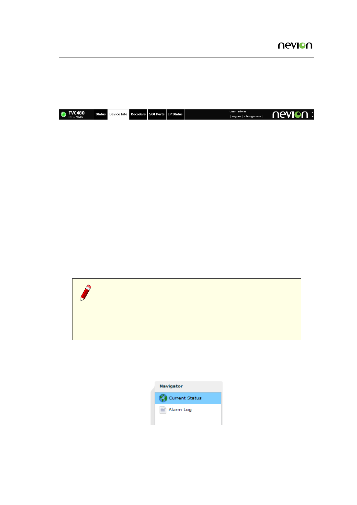
7.2 Status header
After successful login the start page is shown. The top part of the page (shown in Figure 7.3)
is called the status header.
Figure 7.3 The status header
In the status header the product name is shown on the left hand side, along with the T-VIPS
logo. Beside the logo is also shown the current operational mode of the unit.
The status bar displays an indicator showing the overall alarm status of the device. The colour
of the indicator shows the highest level alarm currently active in the unit. It is green if no alarm
is active. Other possible colours are described in Appendix E.
Several items are presented in the right corner/section of the header. Starting from the left:
• The user defined device name, if entered.
• A button to log out from the GUI.
• A button to switch current user level.
• A text showing the current user name.
• The local device time.
• A button for minimising the header. Using this hides a lot of the header information
and gives more space for the rest of the page.
• An activity indicator.
Note: The activity indicator shows one box for each request being
processed by the unit. Each box may change from green to red if ex-
cessive time elapses during the processing. During normal operation, no
squares should turn red. If squares start turning red there might be a problem with
the communication between the device and the computer, or the device may be
busy. If the device has not responded to a request within 20 seconds, the indicator
turns yellow. If no response has been received after 40 seconds, it turns red.
A tab bar is located beneath the status header. The exact number of tabs and tab labelling
depends on the units operational mode and licences. Clicking a tab will open the corresponding
page with a navigation pane to the left as shown in Figure 7.4. This pane is used to navigate
between sub-pages of the tab.
Figure 7.4 Status navigator
TVG480 User’s Manual Rev. 2.8.24 (4422) ID: um_jpeg2000postproductiongateway
Page 37

WEB Interface 37
Note: The navigator can be collapsed to economise on screen space. Click
the vertical grey line with two small arrows to the left of the navigator.
7.3 WEB pages overview
The following lists the hierarchy of WEB pages and sub-pages that may be accessed by clicking
on the tabs shown in the status header. These are described later in more detail.
7.3.1 Status
Current Status
Displays the current status of the unit, including status of all ports and any current alarms.
Alarm Log
Displays the Alarm Log on the unit. It allows download and clearing of the log.
7.3.2 Device info
Product Info
Displays general system information and allows setting the device label. The unit may be
physically identified by flashing the front panel power LED.
Alarms
Displays the status of all System alarms and allows the user to program the severity of
these alarms. Global alarm configuration is performed on this page, as well as alarm relay
configuration and alarm log configuration.
Time Settings
On this page the device clock synchronisation source can be selected and the UTC time
offset can be configured. The internal clock can also be adjusted manually.
Reference Sync
On this page an input reference synchronising signal may be enabled and configured.
Network
Displays status information for the Ethernet interfaces.
Ethernet 1 / Ethernet 2 / Ethernet 3 / SFP / SFP 2
Provides access to network settings for each IP interface of the unit. The number of
IP interfaces actually presented will vary depending on the operational mode and the
HW configuration.
IP Routing
Configures IP routing rules for the unit. The rules tell the unit which interface to use
for different destination IP addresses.
ID: um_jpeg2000postproductiongateway TVG480 User’s Manual Rev. 2.8.24 (4422)
Page 38

38 WEB Interface
TXP Settings
Settings for the TXP protocol, used for remote control/monitoring of the unit by
external systems.
SNMP Settings
Configures SNMP related settings such as destination IP addresses of trap receivers
and community string. Also displays a log of the latest traps sent by the unit.
Tools
Provides network related tools.
Save/Load Config
Provides file management interfaces for configuration profiles. Tasks available from this
page include importing or exporting configuration snapshots as XML files, and management of profile snapshots stored on the device itself.
Maintenance
Centralises hardware configuration as well as software licence information. The information presented contains the unit hardware configuration as well as the unit’s software
licence options. The maintenance page also provides services for performing software
upgrades and entering new licence keys to alter the licensed feature set of the unit.
From the maintenance page, it is possible to reset/reboot the device or restore the system
configuration to factory default settings.
Users
User administration interface for configuring passwords for users associated with each
security level. Auto-login options are also provided here.
GUI Preferences
Provides settings for altering the behaviour of the GUI.
7.3.3 Encoders
This page provides control of the video encoders of the unit.
7.3.4 Decoders
This page provides control of the video decoders of the unit.
7.3.5 SDI Ports
Provides configuration and status of the video data interfaces.
TVG480 User’s Manual Rev. 2.8.24 (4422) ID: um_jpeg2000postproductiongateway
Page 39

WEB Interface 39
7.3.6 IP Status
Provides status information of IP interfaces. Also gives access to enabling and disabling video
IP traffic.
7.4 Status
The status page presents an overview of the device operational status as well as a log of alarm
events.
There are two sub-pages within the status page.
Current Status
Indicates the running status of the device.
Alarm Log
Presents the device alarm log and provides operations for clearing the log or exporting it
as a comma separated value file (.CSV).
7.4.1 Current Status
Figure 7.5 Current status
ID: um_jpeg2000postproductiongateway TVG480 User’s Manual Rev. 2.8.24 (4422)
Page 40

40 WEB Interface
This page displays the current status of the device. It consists of a block diagram illustrating the
device with its input and output ports, an overview of the currently active network interfaces
and a list of currently active alarms.
Block Diagram
The block diagram provides a compact view of the unit status. It shows:
• The name of the functional units of the device.
• The name and alarm status of each input/output port.
• The status of non-I/O port related alarms.
The alarm status is shown with colours indicating the severity of the alarm. The various
severities and colours used are described in
Access to additional information pertaining to the various ports of the block diagram is
provided by hovering the mouse pointer over the port within the diagram. The port
representations in the diagram also act as shortcuts to the corresponding configuration
page for the port. The shortcut is activated by clicking on the port in the diagram.
Right-clicking the status block diagram top bar offers a shortcut to clear device statistics
parameters. Selecting Reset device statistics brings up a dialogue where you can select which
information to clear.
Appendix E.
Current Alarms
The bottom part of the page shows the currently active alarms. Some alarms may contain
several sub-entries that are displayed by clicking on the arrow in front of the entry’s
description. The severity of each alarm is represented by an error indicator (visually
similar to a LED). The colour of the indicator represents the severity level configured for
the specified alarm. The various severities and colours used are described in Appendix
E.
The Current Alarms table contains six columns:
Description
Description of the alarm condition.
For sub-entries, the extended index is shown in brackets. To the left is an indicator visualising the severity of the alarm. The indicator has a tool-tip providing a textual description
of the alarm severity.
On Time
The time when the alarm was raised.
Alarm type
Category of the alarm, i.e. Port, System, Switch etc.
Source
This identifies the source of the alarm. For port alarms, this is a reference to the specific
port raising the alarm. This field has a tool-tip showing the subid1 and subid2 values for
the alarm.
TVG480 User’s Manual Rev. 2.8.24 (4422) ID: um_jpeg2000postproductiongateway
Page 41
WEB Interface 41
Subid1
Reserved for future use in multi-slot chassis and is always set to 1 in the TVG480.
Subid2
The device or port to which the alarm relates. The value is zero for alarms that are
related to the device rather than to a specific port. Values of 1 and up reference
specific ports.
Alarm ID
Each alarm condition has an associated numerical alarm ID.
Details
An optional string to provide more alarm information in human readable form. The format
of this string depends on the alarm type. Hovering the mouse over this field produces a
tool-tip displaying the full text.
A detailed overview of alarm conditions is given in
Appendix E.
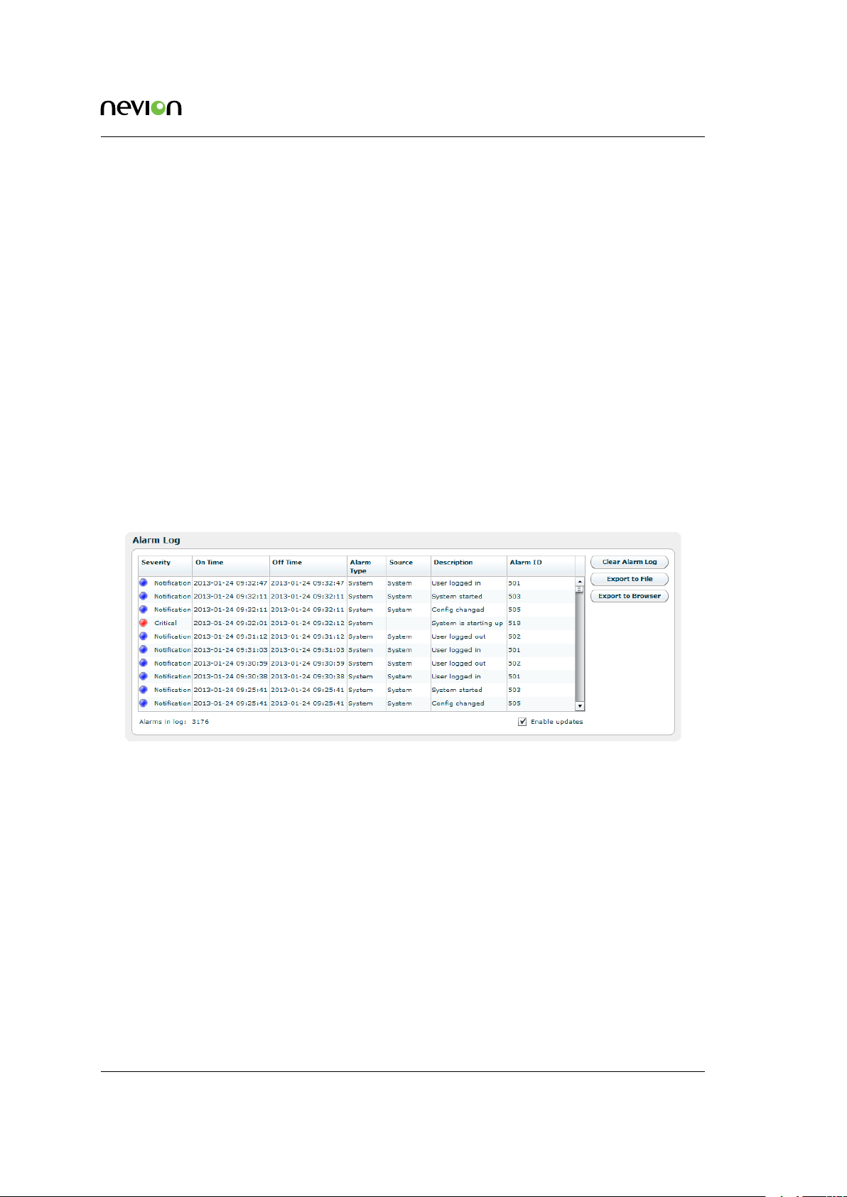
7.4.2 Alarm log
Figure 7.6 Alarm log
The alarm log shows every alarm that has been triggered since the last time the alarm log was
cleared.
The table consists of the same columns as the Current Alarms table, but does not show details
by default. You can change which columns to show, including the details column, in Section
7.5.2.4. Additionally a column named Off Time shows the time the alarm condition was cleared.
Rows will not have the Off Time set if the alarm is still active.
Each row provides additional information via a tool-tip shown when hovering the cursor over
the row. The tool-tip entries are:
Sequence #
A number identifying this specific alarm instance. This number is incremented each time
an alarm condition is raised.
ID: um_jpeg2000postproductiongateway TVG480 User’s Manual Rev. 2.8.24 (4422)
Page 42

42 WEB Interface
SubID 1
The primary numerical index of the alarm instance. This index is reserved for future use
and is always set to 1 in the TVG480.
SubID 2
The secondary numerical index of the alarm instance. When the alarm is of type Port
alarm this index contains the port number for which the alarm was raised. Other types of
alarms may use this index to identify a sub module, but normally it is set to 0.
SubID 3
The tertiary numerical index of the alarm instance. The use of SubID 3 depends on the
type of alarm. Some of the Port type alarms use this index to signal the PID value or
Service ID for which the alarm was raised. For example, if the CC Error of a PID is raised
then the PID value is given by SubID 3.
Details
An optional string providing more information about the alarm in human readable form.
The content and format of this string depends on the alarm type.
Beneath the alarm table is a caption showing the total count of alarms currently stored in the
alarm log.
To the right of the table are three buttons and a check box.
Clear Alarm Log
Clears all alarms from the alarm log.
Export to File
Saves the alarm log to a comma-separated value (.CSV) file. The button opens a file
dialogue where the user can choose the destination to save the file on the computer.
Export to Browser
Opens the complete log in a new browser window, showing the alarm log as a commaseparated value list. The format of this list is a text file (not HTML or XML).
Enable updates
This check box can be unchecked to stop the log from scrolling if new alarms are triggered
while watching the log.
The alarm log is stored in non-volatile memory, so the content is kept even if the unit is rebooted.
The log is circular. Events occurring after the maximum number of entries has been reached
overwrite the oldest entries in the log. The maximum number of stored entries is 10000.
7.5 Device Info
The device info page contains all the information and settings that are not related to a single
input or output port. It is divided into multiple sub pages accessed via the navigation list to
the left. In the list of physical interfaces in the navigation list, the currently active interface is
shown in bold. See Figure 7.7.
TVG480 User’s Manual Rev. 2.8.24 (4422) ID: um_jpeg2000postproductiongateway
Page 43

WEB Interface 43
Figure 7.7 Device
Info navigator
The exact layout of the navigator depends on the resources and features currently available in
the device.
7.5.1 Product info
The product info page contains general device information.
Figure 7.8 Product Information
Name
Configures the current user defined name of the unit. This parameter, together with the
management network parameters are used as device identifiers and remain untouched if
the unit configuration is changed by loading a different configuration file. See
7.5.6. The device name is shown in the web GUI status header (see Section 7.4.1), and in
the web browser title bar to facilitate identification of each device.
Section
ID: um_jpeg2000postproductiongateway TVG480 User’s Manual Rev. 2.8.24 (4422)
Page 44

44 WEB Interface
Inventory ID
Configures the current user defined inventory ID of the unit. This parameter, together with
the management network parameters are used as device identifiers and remain untouched
if the unit configuration is modified. It is only intended as a label/tag and will not affect
the operation of the unit.
Configuration ID
Configure a user defined name for the current configuration of the unit. This name will, if
given, be diplayed in brackets after the unit name in the status header as shown in Figure
7.3. The Configuration ID does not, as opposed to the Name and Inventory ID fields, remain
untouched when loading a new unit configuration. Loading a new unit configuration will
change the Configuration ID. See Section 7.5.6 on how to load a new configuration.
Product name
Displays the name of the product as designated by T-VIPS.
Serial number
The serial number of the device.
Software version
The version of the software currently installed on the device. The software version is given
by the following syntax:
<major_version>.<minor_version>.<patch_version>
The convention for the SW version numbering is as follows:
major_version
Incremented for significant SW changes.
minor_version
Incremented for minor changes. The minor version number is even for official retail
releases and odd for beta releases.
patch_version
If minor_version is even, patch_version gives the patch level of that version. A patch
level of zero means the SW is built on the latest code base, an even patch_version
means this is a released SW patch on a previous release. An odd patch_version means
that this is a test version. If minor is odd, this is a beta version, and the patch_version
simply gives the build number.
Software build time
Reports the time of which the current release image was built.
Device up time
The amount of time that has passed since the device was last reset.
Internal temperature
This shows the current internal temperature of the unit in degrees Celsius and Fahrenheit.
Fan speed
This bar chart shows the current speed of the device fans relative to full speed.
TVG480 User’s Manual Rev. 2.8.24 (4422) ID: um_jpeg2000postproductiongateway
Page 45

WEB Interface 45
Flash Power LED button
The Flash Power LED button activates flashing the green power LED on the device in
question. This is useful for identifying which device is currently being configured. Each
click of the button extends the blinking period by five seconds up to a maximum of about
30 seconds of blinking.
7.5.2 Alarms
The Alarms page is shown in Figure 7.9:
Figure 7.9 Alarm configuration
This page displays the status of all system alarms and allows the user to program the severity
of these alarms. Global alarm configuration is performed on this page, as well as alarm relay
configuration and alarm log configuration.
It gives access to the following sub pages:
• Device Alarms
• Global configuration
• Relay and LED configuration
• Alarm Log Settings
ID: um_jpeg2000postproductiongateway TVG480 User’s Manual Rev. 2.8.24 (4422)
Page 46

46 WEB Interface
7.5.2.1 Device alarms
The page shown in Figure 7.9 provides the administrator with an interface to view the status
and configure the behaviour of all alarms related to the system. At the top the Reset Alarm
Counters button allows resetting all alarm counters simultaneously.
The page is divided into two parts. On the left is a tree that shows all the alarms. The colour
of the folder icon and the specific indicator represents the current status of the alarm. The text
to the right of the tree shows the currently configured severity of the alarm.
The right hand side of the page displays the Alarm Details field when an alarm is selected:
Alarm ID
The internal numerical ID of the selected alarm.
Alarm
Title of the alarm.
Description
Brief description of the condition of the alarm.
Severity
A configurable option defining the severity of the alarm. Options in the pull-down box
range between Filtered (meaning ignored) to Critical. The text in brackets represents the
default setting.
Alarm turned on
The number of times the alarm has transitioned from off to on since last reset of the alarm
counter.
Error count
Not used.
’Reset Counters’ button
When clicked, clears the alarm counters for the current alarm.
The right-click context menu of the device alarm page provides an option to reset the counters
of all the alarms in the Device Info tree.
7.5.2.2 Global configuration
This page provides an interface to configure globally the behaviour of all alarms. By default
ports use the global configuration settings but each port alarm can be configured individually
to override these settings.
For each alarm a custom severity level can be configured. In addition the alarms can be omitted
from the alarm log and trap transmission.
Edited rows are highlighted until changes have been applied.
Tip: For the Log and Send Trap columns, you can quickly select/deselect
all items by right-clicking on the header fields in the columns.
TVG480 User’s Manual Rev. 2.8.24 (4422) ID: um_jpeg2000postproductiongateway
Page 47

WEB Interface 47
Figure 7.10 Global alarm configuration
7.5.2.3 Relays and LED
This page lets the user configure the alarm severity level that shall turn the relay and alarm LED
on. Note that the Alarm relay and the Alarm LED will always be enabled for alarm severity
level Critical, as indicated by the disabled check boxes in the Relay and LED level triggers field.
The current state of the relay and LED is indicated inside the associated brackets.
Figure 7.11 Relays and LED configuration
For further details on the physical relays refer to Section B.5.1.
ID: um_jpeg2000postproductiongateway TVG480 User’s Manual Rev. 2.8.24 (4422)
Page 48

48 WEB Interface
The Virtual Relays field shown in Figure 7.11 also includes settings for the so-called virtual
relays. These are programmable status indicators that can be set to react to any specific alarm
condition. In the simplest case you may want to enable a relay in case a specific alarm ID turns
up. In another case you may want to enable a relay if a specific alarm turns up on a given port.
Each relay status are exported on SNMP. Activation of a virtual relay also generates a specific
alarm, named "Virtual alarm relay activated" (ID=169).
The key element in the settings of the virtual relays is the Expression value. The expression is
very close to SQL in syntax and specifies when the relay should be activated. The behaviour is
as follows for each virtual relay:
1. Each active alarm event is evaluated against the Expression for the virtual relay (if
enabled).
2. If the expression evaluates to true, the Count value is increased by 1. You can at any
time see the current count value. The Count value simply tells you how many of the
current (active) alarm events in the unit that matches the expression.
3. If the count value is larger than or equal (>=) to the Count Thresh. value the relay is
activated.
The expressions are validated before they are accepted by the unit.
Table 7.1 shows the field
values you may enter in an expression.
Table 7.1 Legal field values to use in expressions
Field name Extracts from event: Type Sample expression
id Alarm ID Number id = 169
text Alarm text Text text = ’Defective fan’
type_num Type number Number type_num = 13
type_text Type text Text type_text = ’port’
sev Severity (number 2-6) Number sev = 6
details Alarm details (text) Text details = ’PID 113’
subid1 Alarm subid1 value Number subid1 = 1
subid2 Alarm subid2 value Number subid2 = 2
subid3 Alarm subid3 value Number subid3 = 1190
port Synonym for subid2 Number port = 2
service Synonym for subid3 Number service = 102
pid Synonym for subid3 Number pid = 2000
In the expressions you may enter parentheses to group sub-expressions together. Together with
the supported list of operators this gives great flexibility in constructing advanced “match”
patterns.
Table 7.2 summarises the operator types you are allowed to use. Please note that the examples
below are used for illustration purposes only. For example, the plus and minus operators may
not be very useful in practise, but they are included in this table for completeness.
TVG480 User’s Manual Rev. 2.8.24 (4422) ID: um_jpeg2000postproductiongateway
Page 49

WEB Interface 49
Table 7.2 Legal operators to use in expressions
Operator Description Sample
= Equal id = 169
!= Not equal id != 169
AND Logical AND id = 169 AND port = 2
OR Logical OR id = 169 OR id = 200
IN Set operator. Returns true if left-hand part is included in set to the right. id IN (169,200,201)
+ Addition id + 9 = 169
- Subtraction id - 8 = 160
* Multiply id * 10 = 100
/ Divide id / 20 = 8
> Greater than id > 100
< Less than id < 90
>= Greater than or equal id >= 100
<= Less than or equal id <= 100
Some examples are given in Table 7.3.
Table 7.3 Expression examples
Task Expression Count threshold value
To generate an alarm when any alarm with
ID = 200 turns up (independent on source)
To generate an alarm when alarm with ID =
200 turns up on port with ID = 1 (subid2 =
1)
To generate an alarm when alarm with ID =
200 turns up on both port 1 AND port 2
id = 200 1
(id = 200) AND (port = 1) 1
(id = 200) AND ((port = 1) OR (port
= 2))
2
Note the last example in the table: Here the count threshold value must be set to 2 to get the
expected behaviour. This is because the expression entered matches two different alarm events
(port=1 or port=2), and in order to match them both two matches are required in the global
alarm list.
7.5.2.4 Alarm log settings
This page is used to set alarm log properties.
Log delimiter
This parameter is used when exporting the alarm log. It specifies the column separator
character. The default value for the delimiter is ;. The character used may affect autoimporting of the exported file into your favourite tool used to inspect the file content.
ID: um_jpeg2000postproductiongateway TVG480 User’s Manual Rev. 2.8.24 (4422)
Page 50

50 WEB Interface
Figure 7.12 Configuring the alarm log
Columns
Each of the columns in the alarm log table has a checkbox. Columns that are selected are
shown on the alarm log page.
7.5.3 Time Settings
Figure 7.13 Time Settings
The time settings page lets the user configure time zone, the source for synchronising the internal
device time clock and set the internal clock in case of failure of all external sources of clock
synchronisation. The main use of the device time is stamping the entries of the alarm log.
The page consists of several parts. Top left is the General box, containing the following parameters:
Current time
The current time as reported by the device.
TVG480 User’s Manual Rev. 2.8.24 (4422) ID: um_jpeg2000postproductiongateway
Page 51

WEB Interface 51
Time zone
Drop-down list to configure the time zone of the unit.
Status
The status of the time synchroniser.
Active
The time source currently in use by the time synchroniser.
The Manual Adjust Time field allows the operator to set the time. The manually configured
time will only be used when no other time sources are configured in the Prioritised time sources
list.
The Timesource prioritisation field contains two lists showing configured time sources. Disabled
time sources are greyed out. Enabled time sources are shown with an indication of the time
source status. The list to the right shows time sources that are defined but not used by the
time synchroniser. Enabled time sources may be moved to the leftmost list by using the arrowleft button, and back again by using the arrow-right button. Time sources in the left hand
list are used by the time synchroniser to set the time. They are listed in prioritised order; the
source with the highest priority at the top. The order of priority can be altered by clicking an
item in the list and using the up or down arrows to the left of the list to increase or decrease,
respectively, the item priority. The time synchroniser will use the time source with the highest
priority whose status is “OK” (represented by a green indicator).
Figure 7.14 Time Settings - Add time source
To add a time source to the system, click the “Add Timesource” button, which brings up the
dialog shown in Figure 7.14 with the following fields:
Timesource type
SNTP
Time source retrieving time from an SNTP server.
ID: um_jpeg2000postproductiongateway TVG480 User’s Manual Rev. 2.8.24 (4422)
Page 52

52 WEB Interface
Server address
Specify the server IP address here.
TDT TOT or STT
Time source retrieving time from DVB TDT, DVT TOT or ATSC STT time tables on a
port.
Input source
Lists ports that can be used as time sources with the selected time source type
(Figure 7.14. Multiple entries can be selected to add more than one time source.
For switched inputs, you may select the time source to get time from the input switch group, which will make the time source retrieve the time from the
currently active input in the switch.
To remove time sources, Select them in the list and click the “Remove Timesource” button. Time
sources for dynamic ports such as IP inputs and Switch inputs, are automatically removed if
the dynamic port is removed.
Located below the lists is also a field to define the maximum allowed time interval between
updates from the currently used time source. Exeeding this interval the source is considered
“Not OK” and the synchroniser selects the next source in the prioritised list.
Upon selecting a time source, the Timesource Details box at the bottom right of the page provides
additional details relating to the selected time source. Depending on the type of time source
selected the box may contain some or all of the following parameters:
Active
A checkbox to enable or disable the time source. Disabled time sources are never updated.
Time sources configured and present in the prioritised list must be removed before they
can be disabled.
IP address
Specifies the IP address of an SNTP time server source to poll for updates.
Type
Type of time source selected. The sources are product dependent, but SNTP is always
available.
Last updated time
The most recent time value received from the time source.
State
The current state of the time source.
Reference
Provides the time reference source address of accessed time source.
Reference stratum
Indicates the hierarchy level of the current time source. The master reference is at stratum
0 (highest).
Reference status
Indicates if the time source is currently governed by a time source at a higher stratum.
TVG480 User’s Manual Rev. 2.8.24 (4422) ID: um_jpeg2000postproductiongateway
Page 53

WEB Interface 53
Reference precision
The expected timing accuracy of the current time source.
7.5.4 Reference Sync
This page provides means to synchronise the video processing of the unit to an external analogue
video signal, typically a black-burst SD signal.
Or to a clock signal derived from an IP input stream. The analogue reference source signal is
connected to the rear panel sync input connector.
Figure 7.15 Reference Sync
The Reference Sync page provides a check box to enable or disable a synchronising source for
the video decoder. The Reference source dropdown menu allows the selection of the source
signal, either the analog reference signal or, if licensed, the input stream of one of the four
decoders.
A status field is provided indicating if the sync signal is present, and the associated video
format. Offset indicates the input clock offset in ppm compared with the internally generated
clock signal.
7.5.4.1 IP RX Video RefSync
The purpose of using an IP input stream as source for reference sync is to approximately
synchronize the video output clock on the decoder to the video clock of the input signal to
the encoder. On the encoder, the video input signal determines the exact rate at which packets
are transmitted. On the decoder, the video output clock, and hence the rate at which data
is consumed and decoded, is derived from the decoding unit’s internal clock. If there is a
difference between the video input clock and the video output clock (in the ppm range), the
decoder will periodically either accumulate or run out of data, leading to frame skips or frame
repeats.
Using the IP RX Video RefSync feature, the internal clock on the decoding unit is adjusted to
the “clock” of the incoming data stream. By sampling the arrival time of incoming packets, the
video clock of the video input signal is reconstructed at the encoder and the internal clock is
synchronized to this reconstructed clock signal. This way, the internal clock of the decoding
unit will run at the same clock frequency as the video input signal. Thus the decoder will not
accumulate or run out of data and frame skips and frame repeats will be avoided.
The Sync loss action allows chosing how to respond to sync loss on the source signal. The Sync
loss action is only available when using an IP input stream as the refsync source. Full resync“
ID: um_jpeg2000postproductiongateway TVG480 User’s Manual Rev. 2.8.24 (4422)
Page 54

54 WEB Interface
resets the regulator and waits for the source signal to return. Catch uptries to remain in the current regulating state and catch up with the source signal when it returns. Freewheelingremains
in the current regulator state until a different source signal is received or the user changes the
configuration.
7.5.4.2 Alarms
Alarms related to reference sync are listed on the Alarms page. Clicking an alarm opens the
field to configure the alarm. Please see Section 7.5.2 for alarm configuration details.
7.5.5 Network
Figure 7.16 Network status
This page presents status information about network interfaces, including virtual (VLAN) interfaces, present on the device. The management interface is always present, and bold characters
indicate the web management interface connection. An interface shown in grey colour means
that the interface is disabled. There may be physical interfaces on the unit that are not shown
in this table as the availability of each interface may vary with the installed software licences
and operational mode.
Interface
A label identifying the interface. If it is a physical interface with virtual interfaces attached to it an arrow is shown. Clicking this arrow will expand/collapse the list of virtual
interfaces.
IP Address
The IP address configured for this interface.
TVG480 User’s Manual Rev. 2.8.24 (4422) ID: um_jpeg2000postproductiongateway
Page 55

WEB Interface 55
Link Speed
The current link speed detected for this interface. Applicable to physical interfaces only.
Duplex Mode
The duplex mode detected for this interface, half or full duplex. Applicable to physical
interfaces only.
TX Bitrate
The bitrate currently transmitted through this interface. Applicable to physical interfaces
only.
RX Bitrate
The bitrate currently received through this interface. Applicable to physical interfaces
only.
Enabled
Shows whether the interface is currently enabled.
Data
Shows whether data traffic is currently enabled for this interface.
Management
Shows whether management traffic is currently enabled for this interface.
7.5.5.1 Interfaces
Each available network interface has an entry in the Navigator list. Selecting an interface brings
up pages where it is possible to configure the interface and view its status. Accessible parameters vary with the interface selected since the functionality of the available interfaces are not
necessarily identical.
7.5.5.1.1 Main
Figure 7.17 Main IP settings
This page provides the main configuration settings for the physical interface.
ID: um_jpeg2000postproductiongateway TVG480 User’s Manual Rev. 2.8.24 (4422)
Page 56

56 WEB Interface
Caution: Modifying the settings of the interface you are currently using
for the GUI application may cause loss of contact with the unit. Make sure
you will still be able to contact the unit before applying changed settings.
7.5.5.1.2 Interface Settings
Enable interface
Enables/disables the interface. It is not possible to disable the currently used management
interface.
Speed/duplex mode
The speed and duplex mode of the interface. The Auto setting enables automatic speed
and mode negotiation for the Ethernet link. This option is not available for SFP interfaces.
Note: Modifying the default settings of interface duplex to anything other
than auto can cause unpredictable results unless all peer systems accessing
the port use similar settings. For more technical information regarding auto
negotiation and duplex mismatch, refer to the
Wikipedia duplex mismatch article
(http://en.wikipedia.org/wiki/Duplex_mismatch).
Automatic IP address
Enables automatic IP address assignment using DHCP. This option requires that a DHCP
server is present on the network on which the device is connected.
7.5.5.1.3 DHCP Settings
Hostname
The DNS hostname of the interface. This name is sent to the DHCP server with a request
to register it at the DNS server. If the name registers correctly, the fully qualified domain
name of the interface will be the hostname pluss the domain name assigned by the server.
Domain
Optional field where wanted domain name can be specified. Normally the DHCP decides
the domain name for a client, the DHCP server must be set up specifially to allow a client
to select a domain name.
Renew button
Press button to renew address now. Renew is done by sending a request for renewal of
lease of existing parameters, using uni-cast to DHCP server.
Rebind button
Press to rebind address. Rebind is done by broadcasting a request for the same IP address
as previously used.
TVG480 User’s Manual Rev. 2.8.24 (4422) ID: um_jpeg2000postproductiongateway
Page 57

WEB Interface 57
7.5.5.1.4 DHCP Status
DHCP status
Shows the current state of the DHCP client (RFC2131, Figure 5).
Possible values are:
Disabled
DHCP is not turned on.
Selecting
Client is broadcasting Discover messages and checking for offers from answering
DHCP servers. Normally the client should immediately receive and answer and
switch to bound state.
Bound
Client has received IP settings and is ready for use.
Renewing
Client is uni-casting request to leasing server to renew previous lease.
Rebinding
Client is broadcasting requests to re-bind to previously assigned address.
Checking
Client is evaluating wether offered IP address is already in use on network.
Backing off
Client received a nack from the server.
DHCP server
The IP of the selected server.
IP address
The IP address assigned to this interface by the server.
Subnet mask
The subnet mask assigned to this interface by the server.
Gateway
The IP address of the gateway to use, assigned by the DHCP server.
DNS servers
Prioritized list of DNS servers to use assigned by the DHCP server. See chapter Section
7.5.5.2 for manual configuration of DNS server addresses.
Note: If the DNS server is not located on a sub-net local to the unit, it
may be required to configure the routing table to route DNS requests to
the correct network interface.
Remaining lease time
Time till the IP address must be renewed.
ID: um_jpeg2000postproductiongateway TVG480 User’s Manual Rev. 2.8.24 (4422)
Page 58

58 WEB Interface
DHCP status info icon
More details on the DHCP client is available on a tool-tip if you hoover over the info icon
next to the “DHCP status” parameter. The fields here are:
Domain
The domain name assigned by the DHCP server. The fully qualified domain name of
the interface is <hostname>.<domain>
Lease time
The duration of the address lease, specified by the DHCP server.
Renew time/Time to renewal
The renew time specified by the server. Normally the client should transmit a renew
request after this time.
Rebind time/Time to rebind
Time specified by server for re-bind.
Messages transmitted/received
Number of messages sent and received by the DHCP client.
Last transmission ID
ID used on last DHCP message transmitted.
7.5.5.1.5 Manual IP Settings
IP address
IP address of the interface.
Subnet mask
The subnet mask of the interface.
Gateway
The default gateway address for the interface.
7.5.5.1.6 Interface Status
MAC address
The Ethernet Media Access Control (MAC) address of the interface.
Link speed
Speed of current connection.
Duplex mode
Shows duplex of current connection.
TVG480 User’s Manual Rev. 2.8.24 (4422) ID: um_jpeg2000postproductiongateway
Page 59

WEB Interface 59
7.5.5.1.7 Detect Settings
Detect configuration
Applies to the Ethernet 1 interface, only.
These two boxes enable read and write attributes of the T-VIPS Detect IP assignment
server module. This server is a stand-alone PC application that can be used to discover
T-VIPS devices on a local network and assign IP addresses to them.
Enabling the Read option makes the TVG480 visible for the T-VIPS Detect on the LAN. If
the Write option is enabled the IP address of the TVG480 may be configured using the TVIPS Detect. These options do not affect the operation of the device from the management
application T-VIPS Connect.
7.5.5.1.8 Alarms
Alarms related to the interface are listed on the Alarms page. Clicking an alarm opens the field
to configure the alarm. Please see
Section 7.5.2 for alarm configuration details.
Figure 7.18 Network interface alarms
At the top of the page two radio buttons are provided to select between displaying error count
or error severity. In addition all alarm counters related to this interface may be reset.
7.5.5.1.9 Advanced
This sub-tab allows configuring advanced IP settings of the interface.
Figure 7.19 Advanced IP settings
ID: um_jpeg2000postproductiongateway TVG480 User’s Manual Rev. 2.8.24 (4422)
Page 60

60 WEB Interface
Allow ping response
Check this box to filter incoming ICMP messages. If this option is not enabled the device
will not answer ping requests to this port.
Allow management traffic
Tick this box to allow management traffic on this interface. It is not possible to disable this
on the interface you are currently using for management.
Allow data traffic
Tick this box to allow data traffic on this interface.
Multicast router
This parameter is not shown in the management interface page.
The IP address of the multicast router. The address here is used in conjunction with the
Use multicast router option in the "IP Config" page of the outputs,
Section 7.6.4.
SFP Module Capacity
Set the link capacity of the SFP module. Used to prevent overflow of interface. This
parameter is only shown for SFP modules.
IGMP version
The preferred IGMP version to use. If fixed is selected the unit will keep trying to use the
selected version even if it is not supported by the network.
7.5.5.1.10 Status
Figure 7.20 Interface Status
This page shows detailed status and error information on the selected physical interface. Different types of interfaces support different status and error parameters; not all parameters listed
will be shown for all interface types.
TVG480 User’s Manual Rev. 2.8.24 (4422) ID: um_jpeg2000postproductiongateway
Page 61

WEB Interface 61
The Ethernet Status field:
Link speed
The detected link speed of the interface.
Duplex mode
The detected current duplex mode of the interface. The duplex mode indicates whether
data may flow in one direction (half duplex) or bidirectionally (full duplex).
The following parameters are available for both received and transmitted packets:
bitrate
The total bitrate received/transmitted.
load
Interface load, measured relative to max speed.
Total packets
The total number of IP packets received/transmitted.
Good packets
The number of IP packets received/transmitted containing valid CRCs.
Multicast packets
The number of IP multicast packets received/transmitted by the interface.
Broadcast packets
The number of broadcast packets received/transmitted.
Octets
The number of octets received/transmitted
The Errors field:
CRC errors
Number of packets received with CRC errors.
Alignment errors
Number of packets detected with alignment errors (non-integer number of bytes).
Receive errors
Number of erroneous packets received.
Missed packets
Number of packets missed.
Link symbol errors
Number of link symbol errors detected.
Carrier extension errors
Number of carrier extension errors detected.
ID: um_jpeg2000postproductiongateway TVG480 User’s Manual Rev. 2.8.24 (4422)
Page 62

62 WEB Interface
Receive length errors
Number of packets with invalid size.
The SFP Info field is only shown if the SFP interface is active. It displays information provided
by the SFP module installed.
7.5.5.1.11 VLAN
Figure 7.21 VLAN configuration
This page is only shown on interfaces with VLAN (virtual interface) support. The page allows
adding, removing and editing virtual interfaces (VLAN) using the selected physical interface.
Current VLANs interfaces are shown in the grid on the left, and parameters for each interface
are edited by selecting the interface in the grid first.
Once editing is finished, clicking the Apply button will commit all the changes. Hitting Refresh
will cancel all changes.
In addition to the Apply and Refresh buttons there are buttons to enable adding and removing
VLANs.
7.5.5.1.12 Main Settings
Enable interface
Enable/disable the virtual interface.
VLAN ID
The VLAN id of this virtual interface. Must be in the range 1-4094. All virtual interfaces
on one physical interface must have a unique id.
VLAN priority
The VLAN priority of this virtual interface. Numers 0 to 7 are valid. For further information on VLAN priority usage, see reference
[7].
TVG480 User’s Manual Rev. 2.8.24 (4422) ID: um_jpeg2000postproductiongateway
Page 63

WEB Interface 63
Automatic IP address
Enables automatic IP address assignment using DHCP. This option requires that a DHCP
server is present on the network on which the device is connected.
7.5.5.1.13 Manual IP Settings
IP address
The IP address of the virtual interface.
Subnet mask
The subnet mask of the virtual interface.
Gateway
The gateway address to use for the virtual interface.
7.5.5.1.14 Advanced Settings
Enable data traffic
Checked box enables the virtual interface to allow video data traffic. Not shown for dedicated management interface.
Enable management traffic
Checked box enables the virtual interface to allow management traffic.
Enable ping
Checked box enables the virtual interface to respond to ping messages.
Multicast router
The multicast router for this virtual interface. Only visible if multicast is allowed.
IGMP ver
Provides selection of the IGMP version to use. Not applicable to the "Control" interface.
7.5.5.1.15 DHCP settings and status
Please refer to
related to DHCP, which are identical to the ones on the main tab.
Section 7.5.5.1.1.2 and Section 7.5.5.1.1.3 for a description of the parameters
7.5.5.1.16 SFP
The SFP tab is visible for the second network interface if this interface is set to use SFP. How
to enable the SFP is described in section 7.5.7.1 , provided the appropriate licence has been
installed .
The SFP tab gives access to three sub-pages: SFP Status, STM-1/OC-3 Config and E3/T3
Config. The two configuration sub-pages reflect that separate configuration files are used to
configure the different SFP module types. For each module type the TVG480 stores a configuration file that can be edited “off-line”. These pages are visible only if SFP configuration has been
ID: um_jpeg2000postproductiongateway TVG480 User’s Manual Rev. 2.8.24 (4422)
Page 64

64 WEB Interface
Figure 7.22 The Device Info > Network > SFP tab
Figure 7.23 The SFP status page
licensed. The settings will not be committed to the module until writing of the file is expressly
initiated.
The SFP Status page, shown in figure Figure 7.23, provides an overview of the module status.
The appearance of the status page and the range of parameters shown depend on the type of
module attached.
The Module General Status field displays the status of the module as seen by the TVG480.
SFP Present
Indicates that the module has been detected by the TVG480.
Vendor
Shows the vendor name.
TVG480 User’s Manual Rev. 2.8.24 (4422) ID: um_jpeg2000postproductiongateway
Page 65

WEB Interface 65
Revision
Indicates the module revision.
Date
Indicates the revison date.
Part number
The module part number.
Transceiver type
The type of transceiver inside the SFP module. Only a limited range of transceivers is
compatible with the TVG480.
Connector type
Indicates the network connector type.
Serial number
The serial number of the SFP module.
The Module <type> Configuration field shows the internal functional status as read back from
the module. The field heading will reflect whether a STM-1/OC-3 or an E3/T3 module is
installed. A discussion of the parameters shown is included in the Config pages description.
The Module (type) Alarms field is shown if the STM-1/OC-3 module is present and shows all
link related alarms settings of the module. Red indicates that the alarm has been raised.
TIM-P
Trace ID Mismatch (Path)
LOS
Loss of Signal
AIS_L
Alarm Indication Signal (Line)
RDI_L
Remote Defect Indication (Line)
UNEQ_P
Payload Label Mismatch (Path)
LOF
Loss of Frame
AIS_P
Alarm Indication (Path)
RDI_P
Remote Defect Indication (Path)
EED
Excessive Error Defect
ID: um_jpeg2000postproductiongateway TVG480 User’s Manual Rev. 2.8.24 (4422)
Page 66

66 WEB Interface
LOP
Loss of Point
SD
Signal Degrade
Refer to product specific documentation for further discussion of these parameters.
The Module (type) Link Status field is shown if the E3/T3 module is present and shows the
status of all link related alarm settings of the module. Red indicates that the alarm has been
raised.
BV
Bipolar Violation
LCV
Line Coding Violation
LOS
Loss of Signal
RDI
Remote Detection Indication
WLD
WAN Loop Detected
EZ
Excessive Zeroes
PCV
P-bit Coding Violation
OOF
Out of Frame
LLD
Lan Loop Detected
LOL
LIU Out of Lock
CCV
C-bit Coding Violation
AIS
Alarm Indication Signal
SS
System Status.
Refer to product specific documentation for further discussion of these parameters.
TVG480 User’s Manual Rev. 2.8.24 (4422) ID: um_jpeg2000postproductiongateway
Page 67

WEB Interface 67
The Module (type) Error Counters field displays errors as they occur, counted during a 15
minute period. Es = Errored seconds, Ses = Severely errored seconds, Cv = Coding violations,
Uas = Line unavailable seconds
Current
The counter increments every time an error is detected, resetting every second.
15mins
Displays the result of the previous 15 minutes counting interval.
Section
“Section” related error counts
Line
“Line” related error counts
Path
“Path” related error counts
At the page bottom is the Clear Module Statistics button. Clicking this will flush all error
counters.
The STM-1/OC-3 Config page.
The STM-1/OC-3 module provides an optical interface for high speed data communications in
SDH or SONET networks. This page provides access to change the configuration settings of
the module. As shown in figure Figure 7.24 the page contains four fields to set operational
parameters. The Alarms and Error counters fields are identical to those described for the SFP
Status sub-page. Editing the configuration settings will alter the SFP configuration file stored
in the TVG480, only.
In the General field the main operational parameters are set.
STM-1/OC-3 present
Indicates if the module has been detected by the TVG480.
Write to module
This box must be checked to allow the configuration file be written to the SFP module.
If the box is not checked the configuration file may still be edited without affecting the
module. If the box is checked the configuration file is written to the module every time
the Apply button is clicked.
Tx clock source
The transmitter clock may be internally generated, or derived from the received data
stream.
Frame type
Select SDH or SONET, respectively, according to the accessed network.
Payload FCS (Frame check sequence)
Check this box to enable FCS error detection.
Disable interface
Not available.
ID: um_jpeg2000postproductiongateway TVG480 User’s Manual Rev. 2.8.24 (4422)
Page 68

68 WEB Interface
Figure 7.24 The configuration page
for the STM-1/OC-3 SFP module
Scrambler
Tick this box to enable the module internal scrambler. Must be ticked to successfully
receive scrambled network data.
Ethernet flow control
A tick enables flow control of Ethernet data from the TVG480 to the SFP module. Flow
control prevents data overflow in the SFP module buffer. Buffer overflow leads to data loss
that would go unnoticed until attempting to decode the data at the receiving end.
In the Fault Propagation field check boxes allow to select which network fault(s) shall cause
shut-down of the Ethernet data flow:
LOS
Loss of signal
AIS
Alarm indication signal
RDI_P
Remote defect indication
In the Thresholds field bit error rate measurements indicate an estimate of the network link
quality. The check boxes allow selection of pre-defined threshold BER values to raise alarms.
For further details refer to the vendor SFP user manual.
TVG480 User’s Manual Rev. 2.8.24 (4422) ID: um_jpeg2000postproductiongateway
Page 69

WEB Interface 69
SOH SD
Section Overhead, degraded Signal Defect
SOH EED
Section Overhead, Excessive Error Defect
POH SD
Path Overhead, degraded Signal Defect
POH EED
Path Overhead, Excessive Error Defect
The Taffic Queues field allows mapping of network traffic queues to VLAN priorities. For
information on VLAN priority usage refer to [7].
To aid troubleshooting while changing configuration the Module Alarm and Module Error Coun-
ters fields of the status page are replicated here.
At the bottom of the page are three buttons:
Apply
Writes changes to the SFP configuration file. Also initiates writing the configuration file to
the module if the Write to module box has been ticked.
Refresh
Cancels changes that have been entered.
Reset Factory Defaults
Only active if the Write to module box has not been ticked. Clicking this button returns
the module to factory default settings but will not affect the settings of the configuration
page. The status of the SFP module is at all times displayed in the SFP Status sub-page.
The E3/T3 Config page.
The E3T3 module provides an electrical interface for high speed data communications in E3 or
T3 networks. This page provides access to change the configuration settings of the module. As
shown in figure
the configuration settings will alter the SFP configuration file stored in the TVG480, only.
Figure 7.25 the page contains four fields to set operational parameters. Editing
E3/T3 present
Indicates if the module has been detected by the TVG480.
Write to module
This box must be checked to allow the configuration file be written to the SFP module.
If the box is not checked the configuration file may still be edited without affecting the
module. If the box is checked the configuration file is written to the module every time
the Apply button is clicked.
Interface type
Click the appropriate button for the network used.
Module protocol
Allows selecting the desired data link protocol for the network; HDLC (High Level Data
Link Control), GFP (Generic Frame Protocol) or cHDLC (Cisco extension to HDLC).
ID: um_jpeg2000postproductiongateway TVG480 User’s Manual Rev. 2.8.24 (4422)
Page 70

70 WEB Interface
Figure 7.25 The configuration
page for the E3/T3 SFP module
Line type
Line protocol selection. Choices vary according to the interface type and data link protocol
selected.
Tx clock source
The transmitter clock may be internally generated, or derived from the received data
stream.
Line code
Must be HDB3 for an E3 interface. Select between B3ZS and AMI for a T3 interface.
Line length
Only applicable for a T3 interface. Allows the output signal to be adjusted according to
the line length to reach the termination point.
FEAC
Far end alarm and control indication. Only applicable for a T3 interface using G.751 line
protocol.
VCAT overhead
Only applicable when using the GFP data link protocol. VCAT allows arbitrary grouping
of VCAT members (STS1 or STS3c timeslots) to accommodate any bandwidth.
TVG480 User’s Manual Rev. 2.8.24 (4422) ID: um_jpeg2000postproductiongateway
Page 71

WEB Interface 71
Payload FCS (Frame check sequence)
For error detection. Only applicable when using the GFP data link protocol.
Scrambler
Only applicable when using the GFP data link protocol. Tick this box to enable the module
internal scrambler. Must be ticked to successfully receive scrambled network data.
GFP keep alive
If enabled, sends 2-3 keep alive messages per second. Enable this parameter if Loss of
Frame (LOF) indication is frequently encountered. Generally relevant to older equipment
types. Only applicable when using the GFP data link protocol in a T3 interface.
Ethernet flow control
A tick enables flow control of Ethernet data from the TVG480 to the SFP module. Flow
control prevents data overflow in the SFP module buffer. Buffer overflow leads to data loss
that would go unnoticed until attempting to decode the data at the receiving end.
In the Fault Propagation field check boxes allow to select which TDM network fault(s) shall
cause shut-down of the ethernet data flow:
LOS
Loss of signal
AIS
Alarm indication signal
RDI
Remote defect indication
LOF
Loss of frame
FEAC
Far end alarm and control
Whether or not RDI, LOF and FEAC are applicable depends on Interface type, Module protocol
and Line type settings.
In the Loss of Signal Behaviour field check boxes allow selecting which TDM condition shall
send an LOS indication to the Ethernet interface:
LOS
Loss of signal
LOC
Receive loss of lock
AIS
Alarm indication signal
RDI
Remote defect indication
ID: um_jpeg2000postproductiongateway TVG480 User’s Manual Rev. 2.8.24 (4422)
Page 72
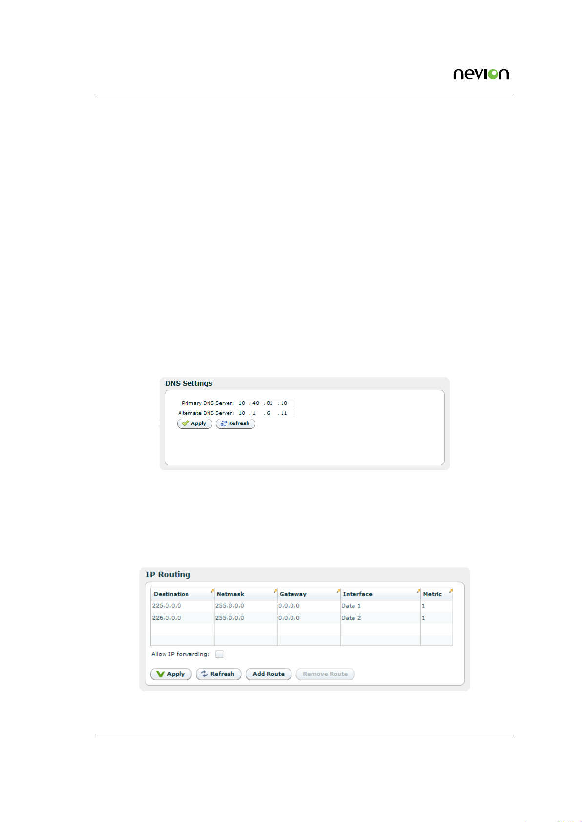
72 WEB Interface
The Taffic Queues field allows mapping of network traffic queues to VLAN priorities. For
information on VLAN priority usage refer [7].
To aid troubleshooting while changing the configuration the Module Alarm and Module Error
Counters fields of the status page are replicated here.
At the bottom of the page are three buttons:
Apply
Writes changes to the SFP configuration file. Also initiates writing the configuration file to
the module if the Write to module box has been ticked.
Refresh
Cancels changes that have been entered.
Reset Factory Defaults
Only active if the Write to module box has not been ticked. Clicking this button returns
the module to factory default settings. This will not affect the settings of the configuration
page. The status of the SFP module is at all times displayed in the SFP Status sub-page.
7.5.5.2 DNS Settings
Figure 7.26 DNS settings
The DNS settings page lets you configure a main and secondary DNS server IP address. The
DNS server is used to map names to IP addresses.
7.5.5.3 IP Routing
Figure 7.27 IP Routing
TVG480 User’s Manual Rev. 2.8.24 (4422) ID: um_jpeg2000postproductiongateway
Page 73

WEB Interface 73
The IP Routing table lets the user configure IP routing rules for the unit. These rules tell the
unit which interface to send IP traffic to, based on the destination IP address of the traffic.
Destination
The destination IP address to use for matching against this routing rule.
Netmask
The subnet mask to use for matching against this routing rule.
Gateway
The IP destination to send a packet to if the destination address of the packet is on a
different subnet than the destination interface.
Interface
IP packets matching this rule will be sent through this interface.
Metric
The metric of the routing rule. If more than one rule matches a destination address the
rule with the lowest metric will be used.
When an IP packet is sent from the unit the destination address of the packet is matched against
the configured routing rules. If the destination address matches one or more rules the rule with
the lowest metric will be used. The packet will then be forwarded to the interface determined
by this rule. If the destination address is on a different subnet than the configured interface the
packet will be sent to the gateway determined by the rule.
Below the table is a checkbox where the user can Allow IP forwarding. If enabled incoming TCP
packets that are not addressed to the unit will be forwarded to an interface according to the
routing rules. The receiving interface must have management traffic enabled to forward TCP
traffic to a different interface.
Note: Modifying the IP routing rules may cause loss of contact with the
unit. Make sure you will still be able to contact the unit with the new
settings before applying the changes.
7.5.5.4 TXP Settings
Figure 7.28 TXP Settings
TXP is a T-VIPS proprietary HTTP/XML based protocol designed to retrieve configuration and
status information using WEB/HTTP requests. TXP exists side by side with an SNMP agent and
ID: um_jpeg2000postproductiongateway TVG480 User’s Manual Rev. 2.8.24 (4422)
Page 74

74 WEB Interface
provides an alternative way to access data in a product. TXP and SNMP therefore complement
each other.
This page contains settings to determine how the unit should respond to TXP queries.
Mode
Controls the mode of the TXP server. If set to Disabled, all TXP accesses are disabled.
Anonymous read
Selects whether read accesses should be allowed without entering user credentials. This
may only be edited if Mode is different from Disabled.
Require HTTP POST for txp_set
Recommended to reduce risk of unwanted configuration changes.
Required level for read
The required user level for TXP read accesses. This may only be edited if Mode is different
from Disabled and Anonymous read is not selected.
Required level for write
The required user level for TXP write accesses. This may only be edited if Mode is set to
Write.
Below follows a simple example of how to get the units uptime. A description of the TXP
protocol can be found on the T-VIPS Product CD, or by contacting T-VIPS Support.
http://10.0.0.10/txp_get?path=/dev/time|_select:uptimetxt
<response request_id="0" method="txp_get" time_stamp="2012-08-17 11:14:20" version="1.0">
<status status="0" status_text="OK"/>
<data>
<dev>
<time uptimetxt="49 days 21h:56m:09s"/>
</dev>
</data>
</response>
7.5.5.5 SNMP Settings
The Simple Network Management Protocol (SNMP) is used to monitor network-attached devices
for conditions that warrant administrative attention. This page gives access to SNMP settings
such as destination IP addresses of trap receivers and community string. It Also displays a log
of the latest traps sent by the unit.
The Trap Destination table lets the user configure the trap servers that should receive SNMP
traps from the unit. To add a server click the Add new button, enter an IP address, then click
the Apply button. To delete an entry select a server entry from the list and click the Delete
button.
The Settings group of parameters configures MIB-2 parameters and SNMP password protection.
The SNMP version to use for traps, version 1 or version 2, may be selected. When selecting to
transmit SNMPv2 traps, two additional options are applicable.
TVG480 User’s Manual Rev. 2.8.24 (4422) ID: um_jpeg2000postproductiongateway
Page 75

WEB Interface 75
Figure 7.29 SNMP Settings
Status change traps
Selecting this causes a trap to be transmitted each time the overall device status changes.
Alarm event forwarding
Configures which alarms to forward as SNMP traps. The drop-down list has the following
options:
Disabled
No traps are transmitted when alarms appear or disappear. If the Status change traps
check box is checked, device status traps are still transmitted.
Basic
The device forwards alarm events as SNMP traps. If there are several sub-entries only
a single trap is transmitted.
Detailed
The device forwards alarm events as SNMP traps. If there are several sub-entries, an
SNMP trap is transmitted for each sub-entry.
The table at the bottom of the page shows the most recent SNMP traps sent by the device.
For more information about the configuration settings for SNMP, please refer to Section 8.4 in
Chapter 8: SNMP.
7.5.5.6 Tools
The tools menu contains helpfull tools for network debugging.
ID: um_jpeg2000postproductiongateway TVG480 User’s Manual Rev. 2.8.24 (4422)
Page 76
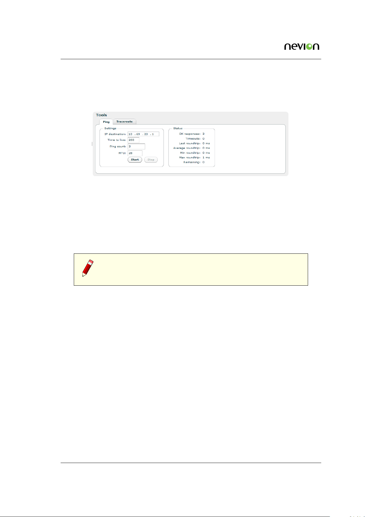
76 WEB Interface
7.5.5.6.1 Ping
The ping tool can be used to check for connectivity between devices. It is especially useful to
ping the receiving data port from the IP transmitter to see if the receiver can be reached.
Figure 7.30 The Ping tool
IP destination
The IP address of the receiving data port. The ping messages will be routed to the matching
Ethernet port, either data or management, or to the port configured as default management
interface if the specified IP address does not match either of the two sub-nets. Note that
if you are pinging between data interfaces, the Allow ping response option on the network
page Advanced tab (see Section 7.5.5.1.3) must be enabled both in the transmitter and the
receiver.
Note: When the IP destination is a multicast address one cannot expect to
receive a response to a ping request. It is recommended to test connectivity
using the device’s actual IP address.
TTL (Time To Live)
Enter the time to live value for the ping messages here. The time to live value is a field in
the IP protocol header that is decremented once for each router that the datagram passes.
When the count reaches 0, the datagram is discarded. You can use this to check the
number of routers between the transmitter and the receiver by starting with a low value
and increment it until ping responses are received. TTL is also specified for each data
channel on the IP transmitter, and must be high enough to reach the receiver. Values range
from 1 to 255.
Ping count
The number of ping messages to send. The messages are transmitted with an interval of
about 1 second.
MTU
Maximum Transfer Unit. Specify a length for the ICMP frames to check that frames with
given length pass through the network. The ICMP data payload size is adjusted to yield
Ethernet frames with the specified length. The ping messages are transmitted with the
“don’t fragment” bit set.
Start
Press this button to start the pinging sequence configured above. The status of the ping
TVG480 User’s Manual Rev. 2.8.24 (4422) ID: um_jpeg2000postproductiongateway
Page 77

WEB Interface 77
sequence is displayed in the status frame. Status values are reset on pressing the start
button. After pressing the start button the label switches to Stop, and the button can be
pressed again to cancel the pinging sequence.
OK responses
The number of ping responses received.
Timeouts
The number of ping requests that were not answered. If the timeout counter is incrementing
while the OK responses counter is zero, there is no contact with the specified IP address.
Last roundtrip
The round trip time measured for the last ping request in units of milliseconds.
Average roundtrip
The average round trip time measured for the ping requests in this session. The value is
reset every time the start button is pressed.
Min roundtrip
The shortest round trip time registered for the ping requests in this session.
Max roundtrip
The longest round trip time measured for the ping requests in this session.
Remaining
The number of remaining ping requests in this session.
7.5.5.6.2 Traceroute
The traceroute tool can be used to debug the network connectivity with a given host by tracking
the router hops between the TVG480 and the host. Traceroute uses ICMP ping messages with
increasing TTL to track the router hops.
Settings
IP Destination
The IP address of the host to check. IP routing decides which interface the ICMP
messages are sent on.
Number of hops
This parameter sets a roof to the number of hops that are tracked. Normally this
parameter can be set fairly low.
MTU
Maximum Transfer Unit. This parameter can be used to transmit messages with a
given length. ICMP messages are transmitted with the don’t fragment bit set to yield
errors when MTU of a link is too small for the frame.
Status
Running
State of tracer.
ID: um_jpeg2000postproductiongateway TVG480 User’s Manual Rev. 2.8.24 (4422)
Page 78

78 WEB Interface
Current TTL
Increasing for each new hop traced.
Trace
Grid showing routers encountered.
Hop
Hop number.
RTT[ms]
Round trip time measured in milliseconds for message returned from router at this
point in chain.
IP Address
IP address of router at this point.
Hostname
DNS resolved host name for IP Address. For this column to be filled in, DNS must
be supported and a DNS server must have been defined either manually or by DHCP
client.
7.5.6 Save/Load Config
Figure 7.31 The Traceroute tool
This page provides an interface for managing the device configuration as “snapshots”. From
here, snapshots of the device configuration settings can be taken and stored locally, or exported
from the device as XML files. Also, previously stored snapshots may be imported and applied.
TVG480 User’s Manual Rev. 2.8.24 (4422) ID: um_jpeg2000postproductiongateway
Page 79

WEB Interface 79
The device allows for up to 8 configuration snapshots to be stored and managed locally, not
including the current running configuration.
7.5.6.1 Save/Load Configs
Figure 7.32 Saving and loading of configuration files
7.5.6.1.1 Save Configuration
This is the interface for exporting the current running configuration as an XML file. Clicking
the Save Config button prompts the user with a standard Save as dialogue requesting a location
to store the configuration file. This location can be any place the user has access permissions to
write files.
During the transfer of the file from the device to the user’s system the user has the ability to
click the Cancel button to cancel the transfer. Note that, depending on the web browser used,
an incomplete file may be left on the user’s system after cancelling.
Upon completion of the transfer the transfer progress bar will turn green. If an error occurs
during the transfer the progress bar will turn red and display an error message.
Files exported from the device using this option contain a complete device configuration and
can be restored to the device at a later time. Or it may be installed on another device using the
Load Configuration option.
ID: um_jpeg2000postproductiongateway TVG480 User’s Manual Rev. 2.8.24 (4422)
Page 80

80 WEB Interface
7.5.6.1.2 Load Configuration From file
The Load Configuration field of the page provides a means to directly import a file-based configuration snapshot as the new running configuration. All options from the snapshot are loaded
and verified before making them active, thereby minimising the risk of errors in the file that
would render the device in a non-operational state.
Clicking the button marked Browse prompts the administrator with a standard system File Open
dialogue allowing the administrator to select the file of his choice to import. Once selected,
clicking Load Config performs the following actions :
• Transfers the configuration snapshot from the administrator’s PC to the device
• Validates the configuration to make sure that all the options in the file are compatible
with each other and with the device itself.
• Presents the user with additional information, such as skipped options
• Activates the configuration
When an import has been successfully completed the progress bar colour turns green and
changes its text to OK. Upon failure at any point the progress bar will turn red, and details of
the reason for the failure will be presented as messages in the Result of last config activation
list.
By default, options specific to the device, including device name and management port network
configuration, are disregarded during the import process. This is a convenience feature allowing
configurations to be easily moved from one device to another. It also makes management easier
in that the Web UI will continue to communicate with the device after a new configuration has
been loaded. The default behaviour can be changed with the load options, please see Section
7.5.6.1.4 for a desciption of the options.
Partial configuration files are supported to allow a subset of configuration options to be changed
instead of the entire unit configuration. Partial configuration files are validated as differences
from the current running configuration upon import before being made active.
7.5.6.1.3 Load Configuration from Remote Device
The Load Configuration from Remote Device makes it easy to copy the configuration of another
device to this device. This device will therefore be a clone of the remote device, except for
device specific parameters such as IP addresses and product name. Loading a configuration
from Remote Device is essentially equal to saving the configuration file of another device, and
uploading it to this device.
The configuration field includes the IP address of the remote device. Entering an IP address
and pressing the Contact Device button will check if the connection is valid and display some
information about the device if successful. If the connection is valid, the Load Config button
will become clickable.
TVG480 User’s Manual Rev. 2.8.24 (4422) ID: um_jpeg2000postproductiongateway
Page 81

WEB Interface 81
Note: It is possible, but not advisable, to load configuration from other
model types. Even if loading from the same model type, loading a configuration might also fail, especially if the two devices have different feature
sets. See Section 7.5.7.1 for a list of features.
Please see next chapter (Section 7.5.6.1.4) for a description of the load options.
7.5.6.1.4 Load options
These options are used to modify the behaviour on configuration loading. The options are
available both when loading from a file (Section 7.5.6.1.2) and when loading from a remove
device (Section 7.5.6.1.3).
Default action
This parameter modifies the algorithm used when modifying lists (collections) in the configuration.
Restore
Modify list to contain exactly the entries specified in the file loaded.
Merge
List entries that are present in the running configuration but not in the file loaded
are left in the list. New entries specified in the file loaded but not in the current
configuation are added. Entries present both in file loaded and in running config are
modified.
Update
Only update nodes that are present in running configuration and in file loaded, i.e
no list entries are added or removed.
Overwrite
This parameter is used to modify how specially tagged parameters are handled during file
loading.
Access control parameters
Tick to overwrite SNMP community strings and TXP access parameters.
Device identifier parameters
Tick off his check box to overwrite the device identifiers device name and inventory
ID. Ethernet Interface IP addresses are not overwritten using this option.
7.5.6.2 Boot Log
This page shows the configuration database status log from the configuration loading at last
re-boot. If the configuration is rejected at boot the previous configuration will not be replaced.
This page may then be inspected to find the reason for rejection.
ID: um_jpeg2000postproductiongateway TVG480 User’s Manual Rev. 2.8.24 (4422)
Page 82

82 WEB Interface
7.5.6.3 Stored Configs
This page provides an interface to management on-device stored configuration snapshots. Up
to 8 full system configuration snapshots can be stored.
Figure 7.33 Locally stored configuration files
The table lists the currently stored snapshots, and columns in the table provide information
specific to each snapshot as follows:
Id
Each entry in the table has an id in the range from 0 to 7.
Valid
Indicates if the uploaded configuration is valid. Configuration that are valid may be activated without errors. A valid configuration is indicated by a green indicator and a invalid
configuration is indicated by a red indicator. A silver indicator in this column signifies
that the slot is empty and available.
Description
An snapshot descriptive text can be entered in this field by clicking on the field itself and
typing text. The length of this field is limited to a maximum of 64 characters.
Date saved
Time stamp when the configuration was uploaded to the unit.
File size
Size of the configuration file.
State
Extra information regarding the configuration.
To the right of the tables several buttons are provided to perform actions on the snapshots:
TVG480 User’s Manual Rev. 2.8.24 (4422) ID: um_jpeg2000postproductiongateway
Page 83

WEB Interface 83
Activate
Loads the selected snapshot as the active configuration of the device. The administrator
will be prompted to verify the decision as this action will overwrite any unsaved changes
on the device.
Snapshot
Stores the current running configuration as a snapshot in the slot selected in the snapshot
table. This operation will overwrite the snapshot currently stored in that position without
prior notification.
Upload
Import a locally stored configuration file.
Download
Download selected configuration file to disk.
Delete
Delete the entry selected in the snapshot list.
At the bottom of the page is the Results of last config action field, which will show the result
of the last action performed.
7.5.6.4 Emergency Switch
This feature allows the TVG480 to communicate with a central emergency switch unit. The
emergency switch unit is designed to facilitate simultaneous configuration switching of all units
under its supervision. In this way the operational mode of a comprehensive system may be
changed at the press of a single button. Contact T-VIPS for further information on the emergency
switch unit.
Communication with the emergency switch is IP based using the UDP protocol. Each unit
enabled for emergency switch control polls the emergency switch repetitively to determine the
switch position. The Emergency Switch tab provides the means to configure the behaviour of
the TVG480 under emergency switch control.
Figure 7.34 Emergency switch
The table lists the rules that have been set up for the emergency switch. Several rules may be
configured, albeit only one should be enabled at any one time.
ID: um_jpeg2000postproductiongateway TVG480 User’s Manual Rev. 2.8.24 (4422)
Page 84

84 WEB Interface
Rule
The list position.
Status
• Green if the rule is enabled and connection to the switch unit is ok.
• Red if the rule is enabled and the connection to the switch is down.
• Grey if the rule is not enabled.
Ip
The IP address of the Emergency Switch unit.
Active
The ID of the configuration that shall be applied when the switch is in the active state.
Inactive
The ID of the configuration that shall be applied when the switch is in the inactive state.
To the right of the table, buttons are provided to set up the switching rule(s):
Add Rule
Opens the configuration pane to configure a new switching rule, see
Edit Rule
Opens the configuration pane for the selected switching rule. See
Delete Rule
Deletes the selected switching rule.
Refresh
Refreshes the list display.
Configure Emergency Switch rule
Figure 7.35.
Figure 7.35.
Figure 7.35 Configuring the emergency switch
The Main settings field has the following parameters:
TVG480 User’s Manual Rev. 2.8.24 (4422) ID: um_jpeg2000postproductiongateway
Page 85

WEB Interface 85
Enabled
A tick in the box enables this rule.
Description
User defined description of the rule.
Ip
The IP address of the emergency switch unit.
Active configuration
The ID of the configuration that shall be applied when the emergency switch is active.
This ID must be the ID of a valid configuration from the Stored Configurations list.
Inactive configuration
The ID of the configuration that shall be applied when the emergency switch is inactive.
This ID must be the ID of a valid configuration from the Stored Configurations list.
The Advanced settings field has the following parameters
Digital input
For future use.
Digital output
For future use.
Refresh interval
The time between each poll of the emergency switch state.
Timeout
Maximum time to wait for a return message from the emergency switch unit.
Connection hysteresis
Number of timouts allowed before the connection to the emergency switch unit is considered broken.
Fallback
If this box is ticked the Inactive configuration is applied if the connection with the emergency switch is broken. Othewise the currently applied configuration will remain when
the connection is broken.
Block user
If this box is ticked no user may change the configuration of this unit if the emergency
switch is in the active state.
At the bottom of the pane the Apply button is used to confirm and apply changes made; the
Cancel button is used to discard changes and close the pane.
ID: um_jpeg2000postproductiongateway TVG480 User’s Manual Rev. 2.8.24 (4422)
Page 86
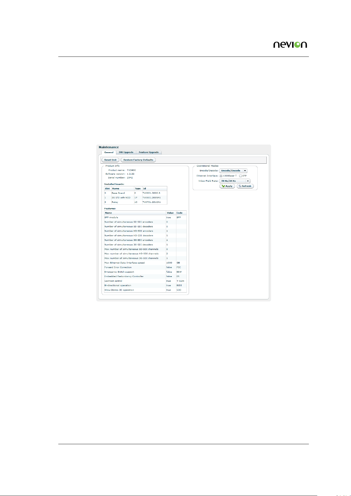
86 WEB Interface
7.5.7 Maintenance
The Maintenance page centralises information regarding the hardware configuration of the device and provides a means for updating firmware images and managing software feature licences.
The page gives access to three sub-pages described below.
7.5.7.1 General
Figure 7.36 Maintenance
The General tab on the maintenance page details the current software, hardware and licence
configuration of the device. Note that the items listed vary between devices.
At the top are two buttons for resetting purposes:
Reset Unit
Provides an interface to perform a restart operation on the unit. Following a restart boot
delay the user is prompted to reload the Web UI in the browser.
Restore Factory Defaults
Resets all non-device specific settings to the factory default settings. Settings remaining
unchanged include the device name and the management interface IP configuration.
The Product info field provides the following information:
Product name
This is the product model name.
TVG480 User’s Manual Rev. 2.8.24 (4422) ID: um_jpeg2000postproductiongateway
Page 87

WEB Interface 87
Software version
The version of the firmware image installed in the unit.
Serial number
The manufacturer assigned serial number used for warranty and software licensing.
Installed boards
The name and serial numbers of the circuit boards installed in each of the internal interface
slots of the unit.
Features
A list of features relevant to the device and their state (e.g. true, false or the number of
ports supported).
Name
Name of the feature
Value
State of the feature or number of licenced items
Code
The factory order code used to identify this feature
Hot
Whether the licence can be upgraded without rebooting the device or not. If the field
reads ’yes’, no reboot will be required after loading a licence upgrade file.
if the SFP Module SW licence key is installed, the Operational Modes frame is visible and
provides the option Electrical/SFP as shown in figure
7.37. This option is used to allocate the
Data-2 IP input to operate through the Electrical Ethernet data interface, or through the SFP
slot.
Figure 7.37 SFP and Electrical Ethernet select
When switching mode the unit will automatically reboot. The device configuration is kept but
references to Data-2 will be invalid.
7.5.7.2 Software Upgrade
The Software Upgrade sub-page lets the user upgrade the software of the device. The page
contains three buttons and a checkbox:
Browse
Prompts the administrator with a standard system Open file dialogue to specify the new
software image file to install.
ID: um_jpeg2000postproductiongateway TVG480 User’s Manual Rev. 2.8.24 (4422)
Page 88

88 WEB Interface
Figure 7.38 Software Upgrade
Upload
Once an image file is specified by using the Browse button, the Upload button is used to
transmit the file from the administrator PC to the device. Once the file has been transferred,
it is verified using and internal checksum value and set as the new active firmware image.
If the upload is successful the progress bar turns green and the unit reboots itself loading
the new image, unless the Reboot on success option has been unchecked.
If the upload is unsuccessful the progress bar turns red and an error message is displayed
in the Status field.
Cancel
The Cancel button is enabled during the upload process and can be clicked to cancel the
operation. It is not possible to continue a cancelled upload.
Reboot on success
This checkbox is checked by default but can be unchecked to disable automatic reboot
upon SW loading completion. If this option is not checked the SW will load but will not
be activated before the user performs a manual reboot. Note that this option is not stored
on the device, and Reboot on success will be enabled next time you enter the SW upgrade
page.
During SW loading, an alarm SW loading in progress is set with the Details field displaying the
IP address of the machine from which the loading was initiated. The alarm is turned off when
the loading is completed or terminated.
If the Reboot on success option is active the unit will automatically reboot when loading is
complete, otherwise an alarm New SW pending is set to indicate that a new SW will be used
on next manual reboot.
After uploading, if the Progress bar shows OK but the web interface does not change to the
Waiting for reset state, allow some time for the device to reset itself and then reload the web
UI via the web browser reload button.
Note: It is recommended to verify the new software version via the “Product Info” page (Section 7.5.1) to verify that the update was successful
and the latest software revision is active.
TVG480 User’s Manual Rev. 2.8.24 (4422) ID: um_jpeg2000postproductiongateway
Page 89
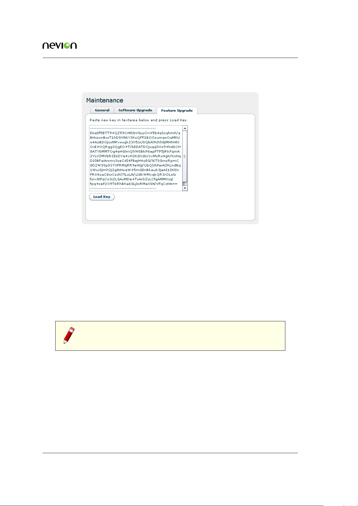
7.5.7.3 Feature Upgrade
WEB Interface 89
Figure 7.39 Feature Upgrade
The Feature Upgrade sub-page provides an interface to upload new software licences to upgrade
the feature set of the device. The licence key is provided as a text file. Paste the content of file
into the text area and click the Load Key button.
Some features do not require a restart of the device when upgraded, they are marked as “hot”
in the feature list. If you load a licence changing only hot-upgradable keys, you will get a
message back in the load text box telling you that no reboot is required. If any non-hot licence
has changed, the device needs to be restarted to activate the new feature(s).
Reset can be performed from the GUI as explained on the Maintenance > General tab in Section
7.5.7.1.
Note: The entire content of the licence key text file must be copied into
the text box, not just a portion of the file.
7.5.8 Users
The Users page provides a configuration interface for user management. Settings are provided
for configuring a password for each privilege level and for configuring automatic login settings.
You must have administrator previledges to alter the settings.
Auto login
Specifies the user privilege level to use for automatic login to the device. Changing this
feature from the default ("No auto login") to another setting bypasses the initial login screen
Figure 7.2) encountered by default.
(
ID: um_jpeg2000postproductiongateway TVG480 User’s Manual Rev. 2.8.24 (4422)
Page 90

90 WEB Interface
Figure 7.40 Users page
Users
Each user privilege level has an account name and password. The account name is fixed
for each level and therefore cannot be changed. Each privilege level, however, has an
administrator definable password.
To modify the password for a given privilege level select the user name from the list
and click the Set password button. The administrator is then prompted with a dialogue
requesting a new password.
Three user privilege levels are available.
guest
Can view configuration information and alarm logs
operator
Can configure the settings on the device, but can not alter passwords
admin
Device administrator, full access to the device.
7.5.9 GUI Preferences
Figure 7.41 GUI Preferences page
The GUI Preferences page contains settings that affect the web interface.
TVG480 User’s Manual Rev. 2.8.24 (4422) ID: um_jpeg2000postproductiongateway
Page 91

WEB Interface 91
Enable confirmation on Apply
Configures the web UI to prompt users for confirmation before committing changes to the
device configuration. When disabled the Web UI will only prompt for confirmation prior
to performing severe operations such as device reset.
Enable GUI scaling
If enabled, the web interface will be shown with the currently configured GUI scale level.
It also enables the use of CTRL + + and CTRL + - to change scale level. When enabling or
disabling this option the web interface may hang for some seconds as it changes the font
used.
GUI scale level
The current scale level for the GUI. This is ignored if GUI scaling is not enabled. A value
of 0 means normal size.
Return to current status page on refresh
Check this to return to status page once refreshing the GUI WEB page. If not checked, you
will return to the last visited sub-page when reloading the page.
Enable sound on critical alarm
This option makes the computer play an alarm sound continuously if browser is connected
to unit while it has a critical alarm. Use with care.
Note: Every browser session will play sound independently of each other
if you enable this on multiple devices and/or have multiple open browsers.
Note: ’Enable confirmation on Apply’ is stored on the device, while the
other options are stored as browser cookies and thereby only affect the
local browser and PC.
7.6 Encoders
This page provides means to control and monitor the operation of the video encoders. The
navigator allows selecting sub-pages to control all parameters related to encoder operation.
7.6.1 Encoders overview
This page gives a view of the status of the encoders and provides the means to select operational
mode (enabling/disabling) of each encoder.
ID: um_jpeg2000postproductiongateway TVG480 User’s Manual Rev. 2.8.24 (4422)
Page 92

92 WEB Interface
Figure 7.42 Encoder Overview
7.6.2 Encoder
For each encoder a page is provided allowing to set the encoder and IP transmission configurations.
7.6.2.1 Main
Figure 7.43 Encoder Main page
TVG480 User’s Manual Rev. 2.8.24 (4422) ID: um_jpeg2000postproductiongateway
Page 93

WEB Interface 93
Figure 7.43 shows the main configuration page. The parameters in the Encoder Configuration
field are:
Label
A label can be attached in order to more easily identify the encoder in a large (multiencoder) system. This name will be reflected in the block diagram of the main status page
(Figure 7.5).
Encoder mode
Enables/disables the encoder. Choices are: Disabled or HD (1.5G).
Max total bitrate
Configures the maximum total bitrate for the encoding process (including audio, VBI and
other data types in addition to video). This bitrate is the Ethernet bitrate, which includes
all transport layers down to Ethernet framing, i.e. from the fields MAC destination to
Frame check sequence (CRC), inclusive.
Constant bitrate
Enables transmission with a constant bitrate, where the bitrate is the configured max total
bitrate. Stuffing packets will be generated to achieve the desired bitrate.
Stereoscopic 3D
Enable this to turn 3D mode on. If enabled, the second encoder will be used as a slave to
this encoder. See
Section 6.4 for details on 3D operation.
Max total bitrate 3D
Only used in 3D mode. Configures the total bitrate to be used for an encoder pair in 3D
mode.
To the right of the encoder configuration field two status fields provide input source status and
encoder status, respectively.
The Input Source Status field shows the status of the available input sources, whether SDI sync
has been acquired, the video format of the SDI input and content of the currently configured
generated signal.
The Encoder Status shows what source is used for encoding, the operational state of the encoder,
the video format of the encoded source, the maximum and current compressed video bitrates,
the current chroma weight and the encoded audio bitrate.
Note: If a signal different from the SDI input signal is used as source
for encoding, either because sync has been lost or because the generated
signal has been chosen, a warning is triggered informing the user of which
signal is used for encoding and why.
In the IP Output Basic Configuration field the IP destination address and UDP destination port
are configured, and a check box is provided to enable or disable the IP stream. It is also possible
to override the automatic selection of destination interface. See Section 7.6.4 for more details.
ID: um_jpeg2000postproductiongateway TVG480 User’s Manual Rev. 2.8.24 (4422)
Page 94

94 WEB Interface
Adjacent is the IP output Status field which indicates the output interface used, whether the
IP address has been resolved (the destination can be reached), and the corresponding MAC
address. This field also shows the total Ethernet output bitrate.
Immediately below these fields, next to the Apply, Refresh and Reset Statistics buttons, there are
two additional buttons, “Add IP Destination” and “Copy IP Destination”. These can be used to
make the Encoder transmit the same contents to several IP destinations, so called IP smallcast,
where an additional IP destination can be configured based on the current one (Copy) or as a
completely new one (Add).
When multiple IP outputs have been configured for the same Encoder, the IP Basic Configuration
and IP Output Status fields are replaced by the IP Destinations list, see Figure 7.44. This list
gives an overview of all configured IP destinations, and each one of these is available for detailed
configuration through the navigation pane on the left hand side.
Figure 7.44 Multiple IP destinations
More IP destinations can be added by pressing the buttons Add New or Copy Selected (after
selecting one of the items in the list), or IP destinations can be deleted by selecting it and
pressing the Remove Selected button.
TVG480 User’s Manual Rev. 2.8.24 (4422) ID: um_jpeg2000postproductiongateway
Page 95

WEB Interface 95
7.6.2.2 Alarms
This page (Figure 7.45) provides access to all alarms related to encoder and associated IP operations. The folder icons may be clicked to expand a list of the individual alarms. Furthermore
each alarm entry may be clicked to show details and to allow configuring the severity level or
reset the error counter. Please see Section 7.5.2 for details on alarm configuration.
Figure 7.45 Encoder Alarms
At the top of the page two radio buttons are provided to select whether to display error count
or error severity. In addition all alarms counters related to this encoder may be reset.
7.6.2.3 JPEG2000
This page (
The chroma weight may be set to a fixed value between 1 and 50%, according to operator
preference, or automatic chroma weighting may be selected by ticking the check box. When
Figure 7.46) gives access to control the JPEG2000 encoding properties.
Figure 7.46 Encoder JPEG2000 page
ID: um_jpeg2000postproductiongateway TVG480 User’s Manual Rev. 2.8.24 (4422)
Page 96
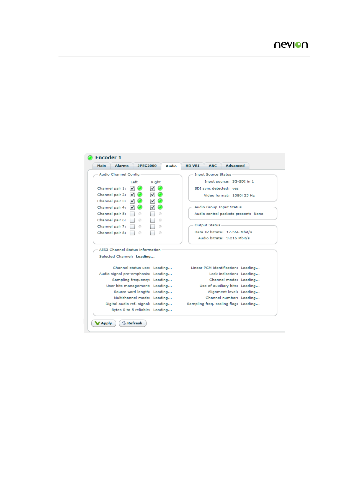
96 WEB Interface
selected, the chroma bitrate weight is automatically calculated based on the total video bitrate.
The chroma weight is then 5% for video bitrates less than 50 Mbit/s, 50% for video bitrates
above 300 Mbit/s and progressively scaled in between.
Integer or floating point processing may be selected in the pull-down list. Two wavelet filters are
supported; the 9/7 floating-point filter and the 5/3 integer filter. The floating-point filter is more
efficient in terms of compression efficiency, while the integer filter is more robust in systems
with multiple JPEG2000 encoding/decoding stages, as rounding errors are not accumulated.
7.6.2.4 Audio
Figure 7.47 Encoder Audio page
The Audio Channel Config field provides switches to include embedded audio channels of the
input SDI signal to be included in the encoding process. A large circle signifies that the audio
channel is present, where green signifies presence of sound and grey signifies silence. A small
grey circle signifies that the audio channel is not present.
Up to 8 audio channel pairs may be present, and the left and right channels of each pair may
be enabled individually. Two status fields are provided to display the audio input and output
status, respectively.
Audio Group Input Status
The audio group input status field displays information on whether audio control packets
are present.
TVG480 User’s Manual Rev. 2.8.24 (4422) ID: um_jpeg2000postproductiongateway
Page 97

WEB Interface 97
AES 3 Channel Status Information
In the AES 3 Channel Status field, one may monitor the AES3 channel status information
that is embedded into the audio channels by clicking on the appropriate audio channel.
7.6.2.5 HD VBI
This page allows the user to configure the insertion of raw VBI data (luma data) into HD signals,
by listing the lines one wants to extract and transmit. A single line of raw VBI data consumes
about 4-500 Kbit/s of the available bitrate.
Note: When raw VBI (luma data) extraction is enabled on a given line,
neither the luma nor the chroma component of that line will not be scanned
for ancillary data.
Figure 7.48 Encoder HD VBI page
7.6.2.6 ANC
This page allows to configure and monitor the transmission of ancillary data. By default, all
ancillary data are transmitted transparently. The horizontal blanking area of every line and all
VBI lines, except for those configured for raw VBI transmission, are scanned for ancillary data.
An alarm is raised if the configured ancillary data bitrate is insufficient for the ancillary data
present in the signal. Also, if the bitrate is insufficient, some ancillary data packets will be
dropped.
Note: Since HD audio control packets are mandatory for HD-SDI, they
will not count against the configured ancillary data bitrate and will be
transmitted even if no ANC bitrate has been reserved.
Ancillary data bitrate
Configure how much bitrate should be reserved for ancillary data. Note that the alarm
ID: um_jpeg2000postproductiongateway TVG480 User’s Manual Rev. 2.8.24 (4422)
Page 98

98 WEB Interface
for insufficient bitrate may be raised, even though the average bitrate used is below the
configured bitrate. This is because the configured ancillary data bitrate must take peak
occurrences of ancillary data into account.
Current ancillary bitrate
This displays the average bitrate used for ancillary data.
Present DIDs
This list monitors the DIDs and SDIDs present in the signal. The list is refreshed continuously. DIDs present only very sporadically may disappear and reappear on the list.
Figure 7.49 Encoder Ancillary Data page
7.6.2.7 Advanced
This page allows the user to configure the sync loss handling and the generated signal. The
sync loss signal and the generated signal can be configured individually.
Encoder action on sync loss
Configure how the encoder should react on losing sync: Stop encoding, encode the last
complete SDI frame or encode a custom image.
Delay before switching
This configures the delay before switching to the configured sync loss action. The default
action on losing sync is to encode a freeze frame, i.e. the last good frame. If the encoder
is configured to encode a freeze frame the encoder will stay in this state until SDI sync is
re-acquired.
Custom image
For both the sync loss signal and the generated signal, one can configure the content of
the custom image. The available custom images are:
• black
• green
TVG480 User’s Manual Rev. 2.8.24 (4422) ID: um_jpeg2000postproductiongateway
Page 99
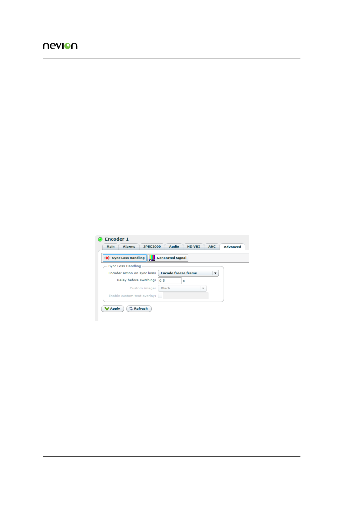
WEB Interface 99
• grey
• magenta
For sync loss handling, the video format of the custom image follows the video format of the
SDI input signal.
Enable custom text overlay
For both the sync loss custom image and the generated signal one may overlay a single
line of white text on the custom image. The font size and position of the text is fixed, the
content can be configured by the user.
Encoder source
On the generated signal page, one may manually override the SDI input signal and force
the generated signal to be used as signal source for the encoder.
Custom format
For the generated signal, one may in addition to the image content select a video format.
The list of available video formats depend on the current configuration of the encoders
and decoders. If the selected video format is not available in the current configuration, the
best available substitute video format is used for the generated signal.
Figure 7.50 Encoder Input Configuration
7.6.3 Encoder, Source
This page allows the user to configure the SDI input source of the encoder. Two sub-pages are
provided.
7.6.3.1 Main
The Config field shows whether or not the input is enabled and allows you to apply a label to
the input.
The Status field shows if the interface is operational (Sync, Checksum errors), the Max capability
of the input, and the input video format.
ID: um_jpeg2000postproductiongateway TVG480 User’s Manual Rev. 2.8.24 (4422)
Page 100

100 WEB Interface
Figure 7.51 Encoder Input Main page
Figure 7.52 Encoder Input Alarms page
The Test output option will route the input the corresponding SDI Output, when the input has
sync. The output will not be reclocked. Note: If changed when port is in sync, the change will
not take effect until sync has been lost.
7.6.3.2 Alarms
Alarms related to the interface are listed on the Alarms page. Clicking an alarm opens the field
to configure the alarm. Please see Section 7.5.2 for details on alarm configuration.
At the top of the page two radio buttons are provided to select whether to display error count
or error severity. In addition all alarms counters related to this encoder may be reset.
TVG480 User’s Manual Rev. 2.8.24 (4422) ID: um_jpeg2000postproductiongateway
 Loading...