

Nevion SL-V1616-CP, SL-V0808, SL-V1602, SL-V1602-CP, SL-V3232 User Manual
...
Nevion Europe AS
P.O. Box 1020, 3204 Sandefjord, Norway – Tel: +47 33 48 99 99 – Fax: +47 33 48 99 98
www.nevion.com
Analog Video Routers
in the
VikinX Sublime series
User manual
Rev. 12

VikinX Sublime Analog Video Routers Rev. 12
nevion.com | 2
Nevion Support
Nevion Europe
P.O. Box 1020
3204 Sandefjord, Norway
Support phone 1: +47 33 48 99 97
Support phone 2: +47 90 60 99 99
Nevion USA
1600 Emerson Avenue
Oxnard, CA 93033, USA
Toll free North America: (866) 515-0811
Outside North America: +1 (805) 247-
8560
E-mail:
support@nevion.com
See
http://www.nevion.com/support/ for service hours for customer support globally.
Revision history
Current revision of this document is the uppermost in the table below.
Rev. Repl. Date Sign Change description
12 11 2009-09-24 NBS Updated Chapter 5.2 with new information about
Ethernet connectivity.
Added extra information about “A/V Toggle” button
in Chapter 7.
11
10
2008-11-21
NBS
Removed GPI information;
Added information about programming of 16x2
CPs.
10 9 2008-11-06 NBS Added/corrected GPI wiring information.
Added protocol configuration information.
Added description of power pin out.
Added description of switching timing options.
9 8 2008-03-27 NBS Updated PSU information.
8 7 2008-02-04 NBS Added Declaration of Conformity;
Added information about 64x64 range;
Added Power GPI information.
7 6 2007-10-08 NBS Removed superfluous information in Chapter 5.3
6 5 2007-10-03
NBS
Added NCB connection information (Chapter 5.3);
Updated some video parameters for 32x32 (and
64x64) routers in Chapter 2.4.
5 4 2007-09-03 NBS Split manuals based on applicable signal format(s);
Added 32x32 range and Chapter 3.5.
4 3 2007-07-02 NBS Corrected Chapter 2.3. (Table).
3 2 2007-06-27 NBS Corrected “Field selectivity” for reference inputs in
Chapters 2.4.
2 1 2007-03-29
NBS
Added Materials declaration and Recycling
information.
1 0 2007-01-23 KB Added connection drawings for SL-V1602 to
Chapter 6.2.
0 - 2006-08-25 KB First release.

VikinX Sublime Analog Video Routers Rev. 12
nevion.com | 3
Contents
1 Product overview .................................................................................................. 4
1.1 Product versions .............................................................................................................. 4
2 Specifications ........................................................................................................ 6
2.1 Mechanics ....................................................................................................................... 6
2.2 Power Supply .................................................................................................................. 6
2.3 Control ............................................................................................................................ 6
2.4 Analog Video specifications ............................................................................................. 6
2.5 Connection details ........................................................................................................... 7
2.5.1 Power Supply pinout .................................................................................................... 8
3 Configuration ....................................................................................................... 9
3.1 Router level...................................................................................................................... 9
3.2 Router mode ................................................................................................................... 9
3.2.1 Router mode on NxN square routers ............................................................................ 9
3.2.2 Router extension mode on 16x2 routers ..................................................................... 14
3.3 Power alarm .................................................................................................................. 14
3.4 Power-up mode / Extension enable ............................................................................... 14
3.5 Configuring output on Single bus panels ...................................................................... 15
3.6 Configuring switching time ........................................................................................... 15
3.7 Configuring protocol options ........................................................................................ 15
4 LED status indication .......................................................................................... 17
4.1 Start-up ......................................................................................................................... 17
4.2 Alarm states ................................................................................................................... 17
4.3 Ethernet states ............................................................................................................... 17
5 Router communication ....................................................................................... 18
5.1 Serial connection ........................................................................................................... 18
5.1.1 Maximum cable length (RS-232) ................................................................................ 18
5.2 Ethernet connection ...................................................................................................... 19
5.2.1 HW limitations ............................................................................................................ 19
5.3 NCB connection ............................................................................................................ 20
5.3.1 Connecting control panels ......................................................................................... 20
5.3.2 Pin-out and cable type ............................................................................................... 20
5.3.3 Termination plug ........................................................................................................ 21
5.3.4 Control bus structure .................................................................................................. 21
5.3.5 Maximum distance between NCB devices .................................................................. 21
6 Connecting signal cables to the router ................................................................ 22
6.1 Video signals .................................................................................................................. 22
6.2 Input extension ............................................................................................................. 22
7 Control Panel operation ...................................................................................... 24
7.1 Button description ......................................................................................................... 24
General environmental requirements for Nevion equipment .................................. 27
Product Warranty .................................................................................................. 28
Important notes regarding Software in the VikinX Sublime router family range ....... 29
Appendix A Materials declaration and recycling information .................................. 30
EC Declaration of Conformity ................................................................................ 31

VikinX Sublime Analog Video Routers Rev. 12
nevion.com | 4
1 Product overview
Nevion are proud to present the 2nd generation of the compact small and medium routing
switcher family, Sublime. With Sublime, Nevion now provide a stable and proven product
line including the most complete signal format and size offering available.
With the new ultra slim, multi format and flexible product range, Sublime fulfils the most
demanding requirements from the professional broadcast market.
This User Manual presents the features, installation and operation procedures of the Analog
Video routers of the Sublime range.
− Router range from 8x8 to 128x128
− Software based Configurator for easy system set-up
− TCP/IP, RS-232 and NCB Control (RJ-45)
− Programmable multi- single- and dual bus control panels
− Ultra Slim frame depth
− Low Power, high reliability design
− Redundant power supply system with front indicators
− Interoperability with existing VikinX routers
− Future proof and flexible product range
VikinX Sublime provides many of the powerful control features that drove the VikinX
Modular range to success. VikinX Sublime is ideal for general purpose facilities, on-air
routing, mobile outside broadcast applications and sophisticated A/V applications.
1.1 Product versions
The following versions of the VikinX Sublime Analog Video Routers are available:
Analog Video – 19” - 1RU, depth 5cm:
SL-V0808 /
SL-V0808-CP
8x8 Analog Video Router (125MHz). Router partitioning,
programmable X-Y control panel (on CP version)
SL-V1616 /
SL-V1616-CP
16x16 Analog Video Router (125MHz). Router partitioning,
programmable X-Y control panel (on CP version).
SL-V1602 /
SL-V1602-CP
16x2 Analog Video Router (125MHz). Programmable Dual bus
control panel (on CP version), Expandable to 64x2.
Analog Video – 19” - 2RU, depth 5cm:
SL-V3232 /
SL-V3232-CP
32x32 Analog Video Router (125MHz). Router partitioning,
programmable X-Y control panel (on CP version).
Analog Video – 19” - 4RU, depth 5cm:
SL-V6464 /
SL-V6464-CP
64x64 Analog Video Router (125MHz). Router partitioning,
programmable X-Y control panel (on CP version).

VikinX Sublime Analog Video Routers Rev. 12
nevion.com | 5
Available Control Panels – 19” – 1RU:
SL-16XY-CP
Multi bus X-Y 16x16 panel.
SL-8XY-CP Multi bus X-Y 8x8 panel.
SL-16D-CP Dual bus 16x2 panel.
SL-32S-CP Single bus 32x1 panel.
SL-32S-CP-GPI Single bus 32x1 panel with GPI / Joystick / Tally interface.
SL-16S-CP Single bus 16x1 panel.
SL-16S-CP-GPI Single bus 16x1 panel with GPI / Joystick / Tally interface.
SL-8S-CP
Single bus 8x1 panel.
SL-8S-CP-GPI
Single bus 8x1 panel with GPI / Joystick / Tally interface.
SL-16XY-CP Multi bus X-Y 16x16 panel.
Available Control Panels – 19” – 2RU:
SL-32XY-CP Multi bus X-Y 32x32 panel.
SL-64S-CP Single bus 64x1 panel.
SL-64S-CP-GPI Single bus 64x1 panel with GPI / Joystick / Tally interface.
Available Control Panels – 19” – 4RU:
SL-64XY-CP Multi bus X-Y 64x64 panel.

VikinX Sublime Analog Video Routers Rev. 12
nevion.com | 6
2 Specifications
2.1 Mechanics
Dimensions: - HxWxD = 44x483x50mm, (19”, 1RU);
- HxWxD = 88x483x50mm, (19”, 2RU);
-
HxWxD = 176x483x50mm, (19”, 4RU).
Safety/Emission standards: Compliant with CE EN55103-1 and 2.
2.2 Power Supply
SL-PWR-40 40W Power Supply Unit for 8x8 – 32x32 versions.
SL-PWR-90 90W Power Supply Unit for 64x64 versions.
AC Supply voltage range: 100-240VAC, 50-60Hz,
Max 1.6A (SL-PWR-40) / Max 3A (SL-PWR-90).
AC Mains connector: IEC 320.
DC output: - +15V, max. 2.2A / -15V, max 1.35A. Maximum 43W
for 8x8 – 32x32 versions;
- +15V, max. 4A / -15V, max 2.5A. Maximum 90W for
64x64 versions.
DC connector: DB9, female.
Status monitoring: Via LED in front of the router/CP.
Safety standards: Compliant with CE EN60950, UL-1950/CSA22.2.
2.3 Control
Standard Features:
Serial port: RS-232 for protocol conversion, to VikinX compact control
protocol, or to third party protocols.
Connector(s): DB9, female.
NCB ports:
For integration with VikinX compact router configuration.
Connectors (2): RJ45 (1 In / 1 Out)
Ethernet port: 10/100BaseT Ethernet bus for external router control.
Connector: RJ45.
Synchronization:
- Analog Black&Burst, looped. Both PAL and NTSC
supported.
- Tri-Level, Looped. For HD signal formats only.
- Distribution of synchronization signals between
several routers.
Connector(s): BNC.
Optional Features:
Control Panel:
-
Optional, built-in control panel available.
-
External control panels available.
2.4 Analog Video specifications
Supported formats:
Broadcast:
-
Composite Analog Video, PAL and NTSC.
- Composite Analog Video, SECAM,
- Analog RGB and
- Analog YCrCb..
Electrical signal specifications:
VikinX Sublime Analog Video Routers Rev. 12
nevion.com | 7
Frequency response: - 100kHz – 5MHz: +0/-0.1dB
- 100kHz – 30MHz: ±0.5dB
-
0Hz – 125MHZ: +0.5/-3dB.
Return loss: -
> 40dB @5.5MHz, 75 ohm BNC
-
> 35dB @10MHz.
Output DC offset error: < 15mV DC.
Gain: 0dB ±0.1dB.
Crosstalk: < -60dB up to 5MHz.
Differential gain: - < 0.1%, for routers up to 16x16;
- < 0.2%, for 32x32 and 64x64 routers.
Differential phase:
-
< 0.1º, for routers up to 16x16;
-
< 0.2º, for 32x32 and 64x64 routers.
Bar tilt: < 0.1%.
Lum. Non-linearity:
-
< 0.1%, for routers up to 16x16;
-
< 0.2%, for 32x32 and 64x64 routers.
Video S/N: > 70dB, unweighted
Max. signal level: > 2Vpp.
Delay difference, any input to
one output:
< ±1nsec.
Connector: 75 ohm BNC female.
Impedance: 75 ohm nominal.
Reference inputs:
Number of inputs: 1.
Connector: 75 ohm BNC female, loop-thru.
Return loss: >40dB (100 kHz – 5 MHz);
>35dB (5-10 MHz).
Signal format: NTSC or PAL Black&Burst.
Signal level: Nominal 1.0Vp-p.
Field selectivity: Field 1.
Timing range:
-
PAL: 30us ±5us after hsync in line 6
-
NTSC: 30us ±5us after hsync in line 10.
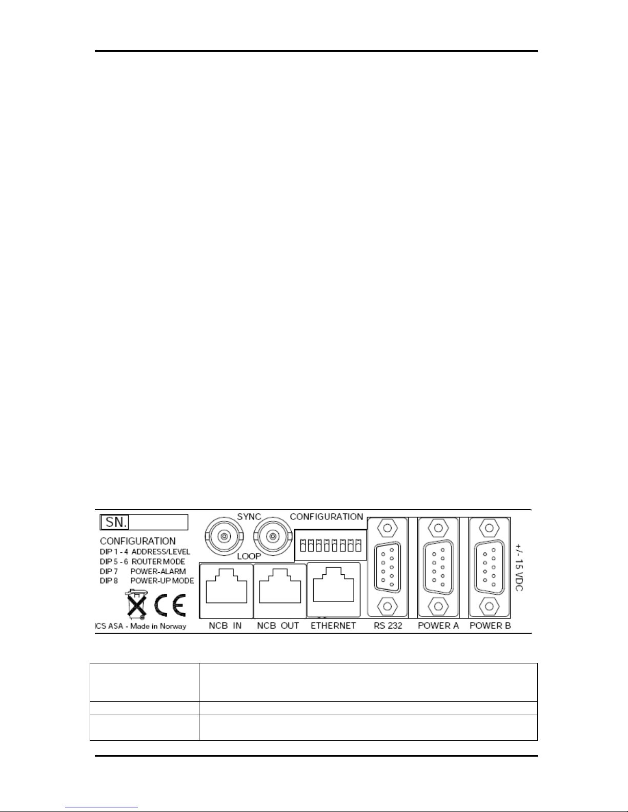
2.5 Connection details
The Sublime routers have the following service connections on the rear of each product:
Figure 1: Sublime service connectors.
SYNC: Synchronization signal (in). Black burst/composite/tri-level sync
reference input with passive loop-through for vertical interval
switching.
LOOP: Synchronization signal (out). Loop-through of SYNC input.
NCB IN: Network Control Bus Input. The protocol of this bus is described in a
separate manual.

VikinX Sublime Analog Video Routers Rev. 12
nevion.com | 8
NCB OUT: Network Control Bus Output.
ETHERNET:
10/100Base-T Ethernet bus for external router control.
RS 232: RS-232 for external control protocols.
POWER A: ±15VDC power connector.
POWER B: ±15VDC power connector, redundant supply.
CONFIGURATION: Configurations switch. See Chapter 3 for further descriptions.
2.5.1 Power Supply pinout
The DB9 power pinout for Sublime routers and Control Panels are as follows;
Pin # Description
1 GND
2
Not connected
3 Not connected
4 +15VDC
5 Not connected
6 Not connected
7
Not connected
8 -15VDC
9 Not connected
VikinX Sublime Analog Video Routers Rev. 12
nevion.com | 9
3 Configuration
This chapter provides an overview of the configuration options that are available on the
Sublime Analog Video Routers.
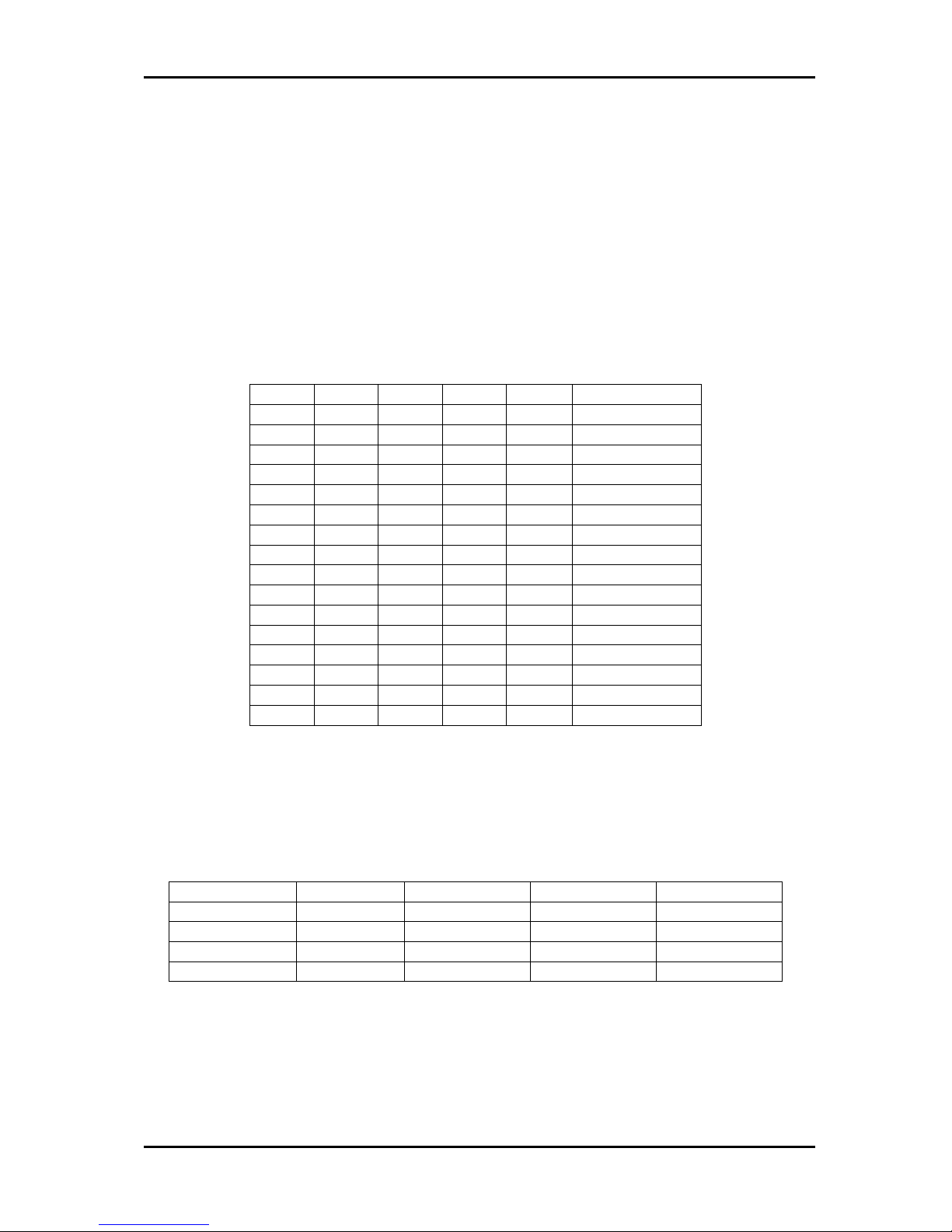
3.1 Router level
Switches 1 - 4 on the configuration switch set the router’s level for communication with the
Router Management System and other units in the NCB system. The panels on the NCB
dedicated to operate with the router must be configured to the same level as that router.
If several routers are combined to form an Audio Follow Video, RGB or similar system, these
routers must be configured to the same level.
The levels can be switched according to the following pattern:
SW 1 SW 2 SW 3 SW 4 Level NCB Address
OFF OFF OFF OFF 1 0
OFF OFF OFF ON 2 1
OFF OFF ON OFF 3 2
OFF
OFF
ON
ON 4 3
OFF ON OFF OFF 5 4
OFF ON OFF ON 6 5
OFF ON ON OFF 7 6
OFF ON ON ON 8 7
ON OFF OFF OFF 9 8
ON OFF OFF ON 10 9
ON
OFF
ON
OFF
11
10
ON OFF ON ON 12 11
ON ON OFF OFF 13 12
ON
ON
OFF
ON
14 13
ON ON ON OFF 15 14
ON ON ON ON 16 15
Default level is 1.
3.2 Router mode
3.2.1 Router mode on NxN square routers
The Sublime A/V router allows switching in different modes:
Router layers 8x8 router 16x16 router 32x32 router 64x64 router
1 layer
8x8
16x16
32x32
64x64
2 layers 4x4 8x8 16x16 32x32
3 layers N.A. 5x5 10x10 21x21
4 layers 2x2 4x4 8x8 16x16
Switches 5 - 6 on the configuration switch set the router’s mode. The Router Management
System software must be configured according to the mode chosen on the router.
VikinX Sublime Analog Video Routers Rev. 12
nevion.com | 10
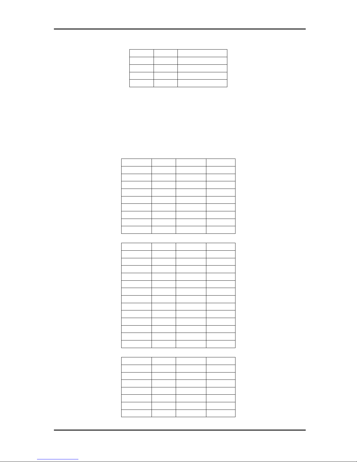
The modes can be switched according to the following pattern:
SW 5 SW 6 Router mode
OFF OFF 1 router layer
OFF ON 2 router layers
ON OFF 3 router layers
ON ON 4 router layers
Default mode is 1 router layer.
Based on the configuration above, the I/O is connected to the router according to the
following scheme, where the physical limitations depend on the type of router that is
purchased (8x8, 16x16, 32x32 or 64x64):
− 1 layer:
I/O is connected according to information on the rear of the router.
− 2 layers, based on an 8x8 router:
Layer 1 Input Layer 1 Output
1 1 1 1
2 2 2 2
3 3 3 3
4 4 4 4
Layer 2
Input
Layer 2
Output
1 5 1 5
2 6 2 6
3 7 3 7
4 8 4 8
− 2 layers, based on a 16x16 router:
Layer 1 Input Layer 1 Output
1 1 1 1
2 2 2 2
3 3 3 3
4 4 4
4
… … … …
8 8 8 8
Layer 2 Input Layer 2 Output
1 9 1 9
2 10 2 10
3 11 3 11
4 12 4 12
… … … …
8 16 8 16
− 2 layers, based on a 32x32 router:
Layer 1 Input Layer 1 Output
1 1 1 1
2 2 2
2
3 3 3 3
4 4 4 4
… … … …
16 16 16 16
Layer 2 Input Layer 2 Output
 Loading...