

Page 1
3GHD-EO-D15xx
3GHD Electrical to Optical converter
for dense wavelength division multiplexing
[Type text]
User manual
Rev. 2
Nevion HQ:
Nevion Europe, P.O. Box 1020, 3204 Sandefjord, Norway
Tel: +47 33 48 99 99 – Fax: +47 33 48 99 98 – www.nevion.com
Page 2

3GHD-EO-D15xx Rev. 2
Nevion Europe
P.O. Box 1020
3204 Sandefjord, Norway
Support phone 1: +47 33 48 99 97
Support phone 2: +47 90 60 99 99
Nevion USA
1600 Emerson Avenue
Oxnard, CA 93033, USA
Toll free North America: (866) 515-0811
Outside North America: +1 (805) 247-8560
E-mail: support@nevion.com
See http://www.nevion.com/support/ for service hours for customer support globally.
Rev.
Repl.
Date
Sign
Change description
2 1 2012-08-23
MR
In chapters “Product overview” and “Specifications”:
- Removed references to 0dBm laser which is
discontinued.
1 0 2010-07-07
AA
Added information about power constraint in Chapter
1.1.
0 - 2009-07-16
AJM
First version and release
Nevion Support
Revision history
Current revision of this document is the uppermost in the table below.
nevion.com | 2
Page 3

3GHD-EO-D15xx Rev. 2
Contents
Revision history .......................................................................................................... 2
1 Product overview ..................................................................................................... 4
1.1 Constraint on number of cards in a frame ........................................................................ 4
2 Specifications .......................................................................................................... 5
2.1 General ........................................................................................................................... 5
2.2 General functions ............................................................................................................ 5
2.3 Optical Output ................................................................................................................. 5
2.4 Electrical Input ................................................................................................................. 6
2.5 Electrical Output .............................................................................................................. 6
2.6 Standards ........................................................................................................................ 6
3 Configuration ........................................................................................................... 7
3.1 Format configuration ........................................................................................................ 7
4 Connector module ................................................................................................... 8
4.1 Mounting the connector module ....................................................................................... 8
4.2 Terminal format support................................................................................................... 9
5 Module status ........................................................................................................ 10
5.1 GPI Alarm – Module status outputs ................................................................................10
5.2 Front panel – Status monitoring ......................................................................................11
6 Flashlink control ..................................................................................................... 12
7 DWDM wavelength ................................................................................................ 13
General environmental requirements for Nevion equipment..................................... 14
Product Warranty ...................................................................................................... 15
Appendix A Materials declaration and recycling information..................................... 16
A.1 Materials declaration ......................................................................................................16
A.2 Environmentally-friendly use period ...............................................................................16
A.3 Recycling information .....................................................................................................17
EC Declaration of Conformity ................................................................................... 18
nevion.com | 3
Page 4
3GHD-EO-D15xx Rev. 2
1 Product overview
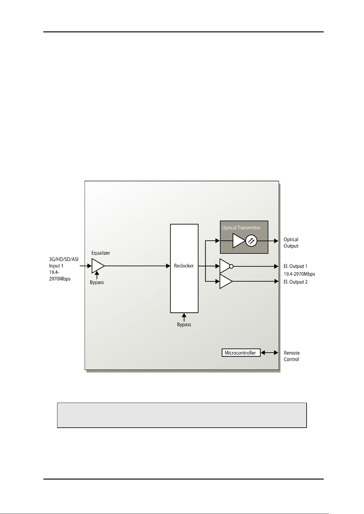
The Flashlink 3GHD-EO-D15xx.xx is a single multi bit-rate electrical to optical converter
module providing high performance media conversion for various signal formats from
19.4Mbps up to 2970Mbps. Unmatched signal accuracy, even in critical applications with
pathological signal patterns makes the 3GHD-EO-D15xx.xx first choice for all optical
transport demands.
The 3GHD-EO-D15xx.xx can transport all HD and SD signal formats in addition to DVB-ASI
and SMPTE310M. It performs electrical equalizing and signal re-clocking, which is selectable
on application. High quality optical transmitters using narrowband temperature stabilized
+5dBm DWDM DFB lasers. 3GHD-EO-D15xx.xx is suitable for medium and long haul
applications. The open system platform of Nevion Flashlink system allows easy
interoperability with third party fiber optical systems.
The 3GHD-EO-D15xx.xx unit has also two electrical outputs, which reduces the need for
additional DA’s. The electrical input is equipped with a multi rate cable equalizer providing an
equalization of typically 75m of high quality coax cable at 2970Mbps.
Figure 1: 3GHD-EO-D Electrical to optical converter
1.1 Constraint on number of cards in a frame
Only 5 cards with DWDM transmitters should be assembled in one Flashlink
frame (FR-2RU-10-2). This constraint applies for both PWR-AC15/15/5/5V and
PWR-AC-75W, in single and redundant power configuration.
This constraint applies also regardless of the normal power consumption of the card, as it is
related to the start current at power up.
nevion.com | 4
Page 5

3GHD-EO-D15xx Rev. 2
2 Specifications
2.1 General
Power +5V DC / 3W, +15V DC/1.5W
Control Control system for access to setup and
module status with BITE (Built-In Test Equip.)
2.2 General functions
Card labeling
Firmware upgrades
Card location in frame through blinking LED
The following parameters can be set and monitored via the web and SNMP interface:
Function Options
Laser On or off
Electrical input Normal or bypass
Reclocker 1 Enable or bypass
Reclocker 2 Enable or bypass
The following parameters can be alarmed via the web and SNMP interface:
Voltage +5V, +3.3V, +5V, +15V and +58V.
Reclocker Loss of lock
2.3 Optical Output
Transmission circuit fiber Single mode 9/125um
Light source DWDM DFB Laser
Optical power +5dBm
Optical centre wavelength According to ITU-T G.694.1 for DWDM
Max number of channels per fiber 40 within the C-band for DWDM.
Channel spacing 100GHz
Max. wavelength drift ± 0.16nm DWDM
Temperature range 0 to +40 °C
Jitter (UI=Unit Interval) 0.135 UI max. @ 270Mbps,
0.2 UI max. @ 1485Mbps
0.2UI typ. @ 2970Mbps
Connector return loss >40dB w/SM fiber
Maximum reflected power 4%
Connector SC/UPC
nevion.com | 5
Page 6

3GHD-EO-D15xx Rev. 2
2.4 Electrical Input
Data rate NRC 19.4 to 2970 Mbps
Data rate re-clocked 270, 1483.5, 1485, 2967 and 2970 Mbps
Equalization Automatic,
Cable equalizer and reclocker can be bypassed to
support bitrates down to 2Mbps
Impedance 75 ohm
Return loss >15dB @ 0-1500MHz
>10dB @ 1500-3000MHz
Signal level Nom. 800mV
Connector BNC
2.5 Electrical Output
Number of outputs 2
Connector BNC
Impedance 75 ohm
Return loss >15dB @ 0-1500MHz
>10dB @ 1500-3000MHz
Jitter max Max. 0.2UI
Peak to peak signal level 0.8V ± 0.1V
Signal polarity - 1 non-inverting,
- 1 inverting
2.6 Standards
Supported standards for electrical and optical ports
SMPTE SMPTE 292M, SMPTE 259M-C, SMPTE 297M,
SMPTE 305.2M, SMPTE 310M, SMPTE424M
DVB-ASI EN50083-9
nevion.com | 6
Page 7

3GHD-EO-D15xx Rev. 2
Switch #
Label
Function, DIP = ON
Function, DIP = OFF
Comment
1
RCL1
Reclocker ON
Reclocker Bypass
Reclocker mode
2
EQ
Cable equalizer ON
Cable equalizer Bypass
Equalizer mode
3
RCL2
Not used
4
R1 5 R2
6
E/O
7
D/B
8
E/O
9
DOP
10
OVR
Override GYDA
control
Config. with DIP
switch
GYDA control
Config. with GYDA
Select configuration
from GYDA
3 Configuration
3.1 Format configuration
The 3GHD-EO-D15xx can support a number of different formats. The correct configuration
can either be set with a DIP switch or with the GYDA System Controller. The layout of
3GHD-EO-D15xx is shown in the drawing below with the DIP switch to the upper left
position.
Figure 2: 3GHD-EO-D15xx.xx board layout
DIP switch configuration must be set according to the table below:
All DIP switches are off when pointing towards the release handle.
nevion.com | 7
Page 8

3GHD-EO-D15xx Rev. 2
4 Connector module
The 3GHD-EO-D15xx has a dedicated connector module: MR-TR-C2. This module is
mounted at the rear of the sub-rack. The module is shown in the figure below. Unused
electrical ports should be terminated with 75ohm.
Figure 3: Connector module for 3GHD-EO-D15xx.xx
4.1 Mounting the connector module
The details of how the connector module is mounted, is found in the user manual for the subrack frame FR-2RU-10-2.
This manual is also available from our web site: http://www.nevion.com/
nevion.com | 8
Page 9

3GHD-EO-D15xx Rev. 2
Terminal
Function
Supported Format
Mode
INPUT
Electrical input
3GHD-SDI, HD-SDI, SDI, DVBASI, SMPTE310, Transparent1
Input
OPT TX
Optical output
(Transmitter)
3GHD-SDI, HD-SDI, SDI, DVBASI, SMPTE310, Transparent1
Input
OUTPUT 1
Electrical Output –
Non inverted
3GHD-SDI, HD-SDI, SDI, DVBASI, SMPTE310, Transparent1
Output
OUTPUT 2
Electrical Output –
Inverted
3GHD-SDI, HD-SDI, SDI,
Transparent1
Output
OPT RX
Not used
GPI ALARM
Open Collector
Alarms
Wired alarms
OC Output
Disable laser
Input
1
4.2 Terminal format support
The different input and output ports on 3GHD-EO-D15xx.xx can support a number of
formats. The table below shows which signal formats are supported on the selected
terminals.
Terminal format support:
3GHD-EO-D15xx.xx has a “Transparent mode”. In this mode all reclockers and CDRs are switched off and no
jitter attenuation will be performed. This mode may be used for non-standard or unsupported bit rates over shorter
distances and up to 1 Gbps.
nevion.com | 9
Page 10

3GHD-EO-D15xx Rev. 2
Signal
Name
Pin #
Mode
Status
General error status for the module
Pin 1
Open Collector
Laser Fail
Laser Fail Alarm
Pin 2
Open Collector
Not used
Pin 3
Open Collector
LOS el
Los of electrical input signal
Pin 4
Open Collector
Laser disable
Turn off laser
Pin 5
Input
Ground
0 volt pin
Pin 8
0V.
5 Module status
The status of the module can be monitored in three ways.
1. GYDA System Controller (optional).
2. GPI at the rear of the sub-rack.
3. LEDs at the front of the sub-rack.
Of these three, the GPI and the LEDs are mounted on the module itself, whereas the GYDA
System Controller is a separate module giving detailed information on the card status. The
functions of the GPI and the LEDs are described in sections 5.1 and 5.2. The GYDA
controller is described in a separate user manual.
5.1 GPI Alarm – Module status outputs
These outputs can be used for wiring up alarms for third party control systems. The GPI
outputs are open collector outputs, sinking to ground when an alarm is triggered. The GPI
input laser disable will turn off the laser if this input is shortening to ground/chassis. The GPI
connector is shown in figure below.
3GHD-EO-D15xx.xx module GPI pinning:
Electrical Maximums for GPI outputs
Max current: 100mA
Max voltage: 30V
Figure 4: GPI output.
nevion.com | 10
Page 11

3GHD-EO-D15xx Rev. 2
Diode \ State
Red LED
Yellow LED
Green LED
No light
Status
Module is faulty
Yellow blinking,
DWDM laser
temperature
stabilizing.
Module is OK
Module power is OK
Module has
no power
LOS/LOCK1
Loss of signal on
electrical output
reclocker
Loss of lock on
reclocker
Signal OK
LOS/LOCK2
Not used
Laser fail
Laser is
malfunctioning.
Laser is off
Laser is OK
5.2 Front panel – Status monitoring
The status of the module can be easily monitored visually by the LED’s at the front of the
module. The LEDs are visible through the front panel as shown in the figure below.
Figure 5: Front panel indicators for the 3GHD-EO-D15xx.xx.
The 3GHD-EO-D15xx.xx has 4 LED’s each showing a status corresponding to the GPI
pinning.
nevion.com | 11
Page 12

3GHD-EO-D15xx Rev. 2
6 Flashlink control
This card uses the FLP 4.0 protocol. See separate documents for definition of this protocol.
nevion.com | 12
Page 13

3GHD-EO-D15xx Rev. 2
No.
[THz]
[nm]
59
195,9
1530,33
58
195,8
1531,12
57
195,7
1531,90
56
195,6
1532,68
55
195,5
1533,47
54
195,4
1534,25
53
195,3
1535,04
52
195,2
1535,82
51
195,1
1536,61
50
195,0
1537,40
49
194,9
1538,19
48
194,8
1538,98
47
194,7
1539,77
46
194,6
1540,56
45
194,5
1541,35
44
194,4
1542,14
43
194,3
1542,94
42
194,2
1543,73
41
194,1
1544,53
40
194,0
1545,32
39
193,9
1546,12
38
193,8
1546,92
37
193,7
1547,72
36
193,6
1548,51
35
193,5
1549,32
34
193,4
1550,12
33
193,3
1550,92
32
193,2
1551,72
31
193,1
1552,52
30
193,0
1553,33
29
192,9
1554,13
28
192,8
1554,94
27
192,7
1555,75
26
192,6
1556,55
25
192,5
1557,36
24
192,4
1558,17
23
192,3
1558,98
22
192,2
1559,79
21
192,1
1560,61
20
192,0
1561,41
7 DWDM wavelength
ITU694.1 DWDM wavelength.
nevion.com | 13
Page 14

3GHD-EO-D15xx Rev. 2
1.
The equipment will meet the guaranteed performance specification under the following
environmental conditions:
-
Operating room temperature range:
0°C to 40°C
-
Operating relative humidity range:
<90% (non-condensing)
2.
The equipment will operate without damage under the following environmental
conditions:
-
Temperature range:
-10°C to 55°C
-
Relative humidity range:
<95% (non-condensing)
General environmental requirements for Nevion equipment
nevion.com | 14
Page 15

3GHD-EO-D15xx Rev. 2
Product Warranty
The warranty terms and conditions for the product(s) covered by this manual follow the
General Sales Conditions by Nevion, which are available on the company web site:
www.nevion.com
nevion.com | 15
Page 16

3GHD-EO-D15xx Rev. 2
組成名稱
Part Name
Toxic or hazardous substances and elements
鉛
Lead
(Pb)
汞
Mercury
(Hg)
镉
Cadmium
(Cd)
六价铬
Hexavalent
Chromium
(Cr(VI))
多溴联苯
Polybrominated
biphenyls
(PBB)
多溴二苯醚
Polybrominated
diphenyl ethers
(PBDE)
3GHD-EO-D15xx
X O O O O
O
O: Indicates that this toxic or hazardous substance contained in all of the homogeneous materials for
this part is below the limit requirement in SJ/T11363-2006.
X: Indicates that this toxic or hazardous substance contained in at least one of the homogeneous
materials used for this part is above the limit requirement in SJ/T11363-2006
50
Appendix A Materials declaration and recycling information
A.1 Materials declaration
For product sold into China after 1st March 2007, we comply with the “Administrative
Measure on the Control of Pollution by Electronic Information Products”. In the first stage of
this legislation, content of six hazardous materials has to be declared. The table below
shows the required information.
A.2 Environmentally-friendly use period
The manual must include a statement of the “environmentally friendly use period”. This is
defined as the period of normal use before any hazardous material is released to the
environment. The guidance on how the EFUP is to be calculated is not finalised at the time
of writing. See
http://www.aeanet.org/GovernmentAffairs/qfLeOpAaZXaMxqGjSFbEidSdPNtpT.pdf for an
unofficial translation of the draft guidance. For our own products, Nevion has chosen to use
the 50 year figure recommended in this draft regulation.
Nevion suggests the following statement on An “Environmentally Friendly Use Period”
(EFUP) setting out normal use:
EFUP is the time the product can be used in normal service life without leaking the hazardous
materials. We expect the normal use environment to be in an equipment room at controlled
temperature range (0ºC - 40ºC) with moderate humidity (< 90%, non-condensing) and clean air, not
subject to vibration or shock.
Further, a statement on any hazardous material content, for instance, for a product that uses
some tin/lead solders:
Where a product contains potentially hazardous materials, this is indicated on the product by the
appropriate symbol containing the EFUP. The hazardous material content is limited to lead (Pb) in
some solders. This is extremely stable in normal use and the EFUP is taken as 50 years, by
comparison with the EFUP given for Digital Exchange/Switching Platform in equipment in Appendix A
of “General Rule of Environment-Friendly Use Period of Electronic Information Products”. This is
indicated by the product marking:
It is assumed that while the product is in normal use, any batteries associated with real-time clocks
or battery-backed RAM will be replaced at the regular intervals.
The EFUP relates only to the environmental impact of the product in normal use, it does not imply that the
product will continue to be supported for 50 years.
nevion.com | 16
Page 17

3GHD-EO-D15xx Rev. 2
A.3 Recycling information
Nevion provides assistance to customers and recyclers through our web site
http://www.nevion.com/. Please contact Nevion’s Customer Support for assistance with
recycling if this site does not show the information you require.
Where it is not possible to return the product to Nevion or its agents for recycling, the
following general information may be of assistance:
Before attempting disassembly, ensure the product is completely disconnected from
power and signal connections.
All major parts are marked or labeled to show their material content.
Depending on the date of manufacture, this product may contain lead in solder.
Some circuit boards may contain battery-backed memory devices.
nevion.com | 17
Page 18

EC Declaration of Conformity
MANUFACTURER
Nevion
AUTHORIZED REPRESENTATIVE
(Established within the EEA)
Not applicable
MODEL NUMBER(S)
3GHD-EO-D15xx
DESCRIPTION
3GHD Electrical to Optical converter
DIRECTIVES this equipment complies with
Low voltage (EU Directive 2006/95/EC)
EMC (EU Directive 2004/108/EC)
HARMONISED STANDARDS applied in order
to verify compliance with Directive(s)
EN 55103-1:1996
EN 55103-2:1996
TEST REPORTS ISSUED BY
Notified/Competent Body
Report no:
Nemko
E08503.00
TECHNICAL CONSTRUCTION FILE NO
Not applicable
YEAR WHICH THE CE-MARK WAS AFFIXED
2008
TEST AUTHORIZED SIGNATORY
MANUFACTURER
AUTHORIZED
REPRESENTATIVE
(Established within EEA)
Date of Issue
2009-07-16
Place of Issue
Not applicable
Sandefjord, Norway
Name
Thomas Øhrbom
Position
VP of Business Support Systems,
Nevion
(authorized signature)
[Type text]
Tel: +47 33 48 99 99 – Fax: +47 33 48 99 98 – www.nevion.com
Nevion HQ:
Nevion Europe, P.O. Box 1020, 3204 Sandefjord, Norway
 Loading...