

Neve GENESYS BLACK User Manual

User Manual
Issue 1.2
Version 3.4 software
Build 2 or later
527-405

IMPORTANT SAFETY INSTRUCTIONS
u Read these instructions
u Keep these instructions
u Heed all warnings
u Follow all instructions
u Do not use this apparatus near water
u Clean only with a dry cloth
u Do not block any ventilation openings.
u Install in accordance with the manufacturer's
instructions.
u Do not install near any heat sources such as radiators,
heat registers, stoves or other apparatus (including
amplifiers) that produce heat.
u Do not defeat the safety purpose of the polarized or
grounding-type plug.
A polarized plug has two blades and a third grounding
prong.
The wide blade or the third prong are provided for your
safety.
If the provided plug does not fit into your outlet, consult an
electrician for replacement of the obsolete outlet.
As this apparatus is constructed to Class I, it shall be
connected to a MAINS socket outlet with protective
earthing connection.
u Protect the power cord from being walked on or pinched
particularly at plugs, convenience receptacles, and the
point where they exit the apparatus.
Where the MAINS plug or an appliance coupler is used as
the disconnect device, the disconnect device shall remain
readily operable.
u Only use attachments / accessories specified by the
manufacturer.
u Use only with the cart, stand, tripod, bracket or table
specified by the manufacturer, or sold with the apparatus.
When a cart is used, use caution when moving the cart /
apparatus combination to avoid injury from tip-over.
- 2 -

u Unplug this apparatus during lightning storms or when
unused for long periods of time.
u Refer all servicing to qualified service personnel.
Servicing is required when the apparatus has been
damaged in any way, such as power-supply cord or plug is
damaged, liquid has been spilled, or objects have fallen
into the apparatus, the apparatus has been exposed to rain
or moisture, does not operate normally or has been
dropped.
WARNING:
TO REDUCE THE RISK OF FIRE OR ELECTRIC SHOCK, DO
NOT EXPOSE THIS APPARATUS TO RAIN OR MOISTURE.
WARNING:
THIS APPARATUS HAS CLASS I CONSTRUCTION AND SHALL
BE CONNECTED TO A MAINS SOCKET OUTLET WITH A
PROTECTIVE EARYTHING CONNECTION.
WARNING:
WHERE THE MAINS PLUG OR AN APPLIANCE COUPLER IS
USED AS THE DISCONNECT DEVICE, THE DISCONNECT
DEVICE SHALL REMAIN READILY OPERABLE.
- 3 -
Symbols used in this manual and on rear of console
Please refer to the manual before operating
Danger of electric shock
Disconnect from the MAINS before opening cover
Heat source
No user serviceable parts inside
Environmental considerations
Temperature Operating 5°C to 22°C
(41°F to 72°F)
Non-operating -20°C to 50°C
(-2°F to 122°F)
Max Gradient 15°C/Hour
(59°F/Hour)
Relative Humidity Operating 20% to 80%
Non-operating 5% to 90%
Max wet bulb 28°C non-condensing
(or 57°F non-condensing)
Altitude Operating 0 to 2,000m
Non-operating 0 to 12,000m
Cooling
Each additional channel section has its own PSU (Power
Supply Unit) located at the rear of the console.
Care must be taken not to place any accessories that could
block the ventilation above or below the heat sinks at the
rear of the console.
All PSU's will operate over an ambient temperature range
of -10°C to +22°C (14°F to 72°F).
The console must not be powered up or operated with the
dust cover still in place.
- 4 -

- 5 -

Health & Safety Notice
FOR YOUR OWN SAFETY AND THE PROTECTION OF
OTHERS, PLEASE OBSERVE THE FOLLOWING SAFETY
HEALTH AND SAFETY INSTRUCTIONS
u READ THESE INSTRUCTIONS AND KEEP THEM HANDY
u HEED ALL SAFETY WARNINGS
u THE CONSOLE MUST BE EARTHED WHEN OPERATED
u DO NOT USE NEAR WATER
u CLEAN ONLY WITH A DRY CLOTH
u DO NOT INSTALL NEAR HEAT SOURCES
u DO NOT BLOCK VENTILATION OPENINGS
u THE AMBIENT ROOM TEMPERATURE SHOULD BE NO
GREATER THAN 22°C / 72°F
u PROTECT THE POWER CORDS
u USE ONLY ACCESSORIES SPECIFIED BY THE
MANUFACTURER
u UNPLUG WHEN UNUSED FOR LONG PERIODS OF TIME
OR DURING LIGHTNING STORMS
u MODULES AND CARDS SHOULD NOT BE INSERTED OR
REMOVED WITH THE POWER ON
u REFER ALL SERVICING TO QUALIFIED PERSONNEL ONLY
u THE CONSOLE MUST ONLY BE MOVED BY AT LEAST TWO
PEOPLE
u NO USER SERVICEABLE PARTS INSIDE
- 6 -
IMPORTANT NOTICE
THE GENESYS CONSOLE IS SUPPLIED WITH A 3-CORE AC POWER
CABLE APPLICABLE TO THE REGION IT IS TO BE OPERATED IN, AND
MUST BE CONNECTED TO A 3-PIN EARTHED SUPPLY.
IF A REPLACEMENT CABLE IS USED, THEN THE EARTH FROM THE
MAINS SOCKET OR TECHNICAL EARTH TO THE CONSOLE MUST BE
MAINTAINED.
IF ONLY A 2-PIN (NO EARTH) SUPPLY IS AVAILABLE, THEN THE
GENESYS CONSOLE MUST BE INSTALLED BY A QUALIFIED
ELECTRICIAN TO ENSURE THAT THE CONSOLE METALWORK IS
PERMANENTLY EARTHED.
THE CONSOLE SHOULD ONLY BE POWERED FROM A SINGLE-
PHASE SUPPLY WITH THE NEUTRAL CONDUCTOR AT EARTH
POTENTIAL.
FAILURE TO FOLLOW THESE PROCEDURES AND RECOMMENDATIONS
COULD INVALIDATE THE MANUFACTURER'S WARRANTY
- 7 -
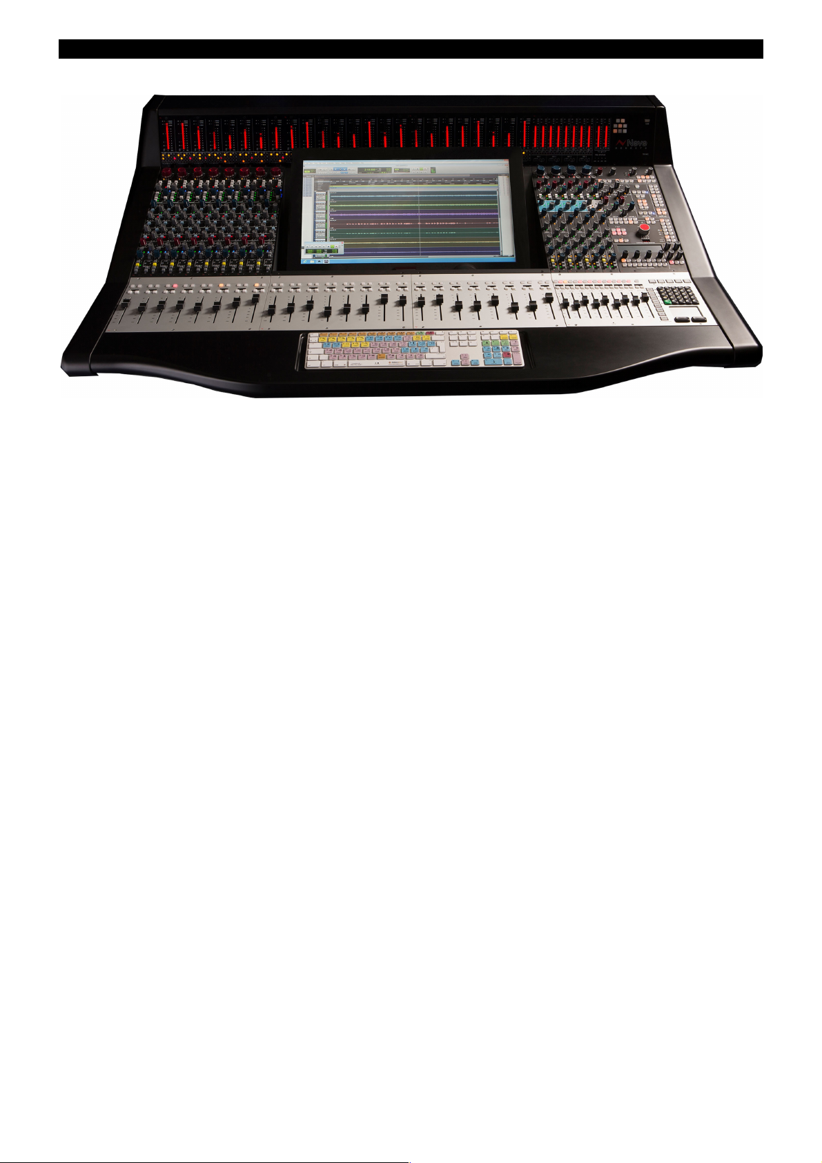
Console Overview
A standard console as shown here will have:
• Integral monitor for DAW computer, with touch-screen control
• Six Auxes (four mono, two stereo)
• Two stereo mix busses (Main Mix LR + 2T)
• Two stereo monitoring speaker sets
• Two 5.1 monitoring speaker sets
• 8 channels of Neve mic/line amplifiers
• 16 dedicated DAW control faders with corresponding stereo DAW metering on meter bridge
• 8 mono Groups
• 4 stereo effects returns with Width control
• 8 Channel, 8 Track, 2 Track plus stereo DAW metering
• 2 independent Cue mixes
• Full talkback (and reverse talkback) capability
• Internal power supply units
• Expandable to 56 channels, either in straight or wedge formation
• USB flash drive for Store, Load & Reset functionality
• Hands-on DAW control for Pro Tools, Logic, Cubase & more
• Full console instant Reset
• Digitally controlled EQ and optional Dynamics (88R or 1084 EQ circuitry and 88R-style Dynamics)
• Motorised 8T and Main Output faders with DAW control
• 8 Channel Analogue DAW Monitor
• Recall software so all rotary control positions can be stored and reset
• AD/DA cassette to provide digital Ins/Outs (16 in, 8 out per card)
• Optional Digital Monitoring cassette providing I/O for Aux, 8T, Main Mix and monitoring
• Motorised Channel Faders with DAW Control
- 8 -

•
Introduction to Genesys Black
For more than 40 years, the designers and engineers at Neve have worked uncompromisingly to produce
the world's premier audio recording and mixing equipment. As a result, Neve products have long
exceeded the most stringent requirements for sound quality and musicality – from countless classic
albums to the vast majority of each year's blockbuster films. Traditionally, such perfection has come at a
price, meaning that only the largest and most prestigious studios could own a Neve recording console.
Until now.
Introducing Genesys Black.
A hand-built expandable analogue recording console with digital workstation control. A console that builds
upon Neve's forty years of technical heritage, including legendary mic pre-amplifiers and highly revered
analogue circuit design.
Genesys Black also accommodates for the seismic changes in methods of music recording, with
extensive digital control and connectivity, placing touch-screen DAW control at the heart of the console.
In any configuration, Genesys Black offers an excellent studio control surface with comprehensive
monitoring and signal routing compatibilities. This eliminates the typical collection of awkwardly
interfaced devices, and puts a proper console back in the heart of the studio.
As with all Neve products, Genesys Black offers sound and build quality beyond reproach. Even the
console stand was developed in conjunction with internationally renowned studio designer Roger D'Arcy
of Recording Architecture in London.
With Genesys Black, the widest possible range of studios can now legitimately claim to be a Neve
facility.
The future begins here.
AMS Neve Ltd
AMS Technology Park
Billington Road
Burnley
Lancashire
England
BB11 5UB
Phone: +44 (0) 1282 417 011
Fax: +44 (0) 1282 417 282
London Office:
+44 (0) 2074 323 858
Email: info@ams-neve.com
Web: www.ams-neve.com
Please check the AMS Neve website periodically for the latest issue of this manual.
© ® 2008 - 2015 AMS Neve Ltd own the copyright of all information and figures contained in this manual which are not to be copied or reproduced by any
means or disclosed in part or whole to any third party without written permission. As part of our policy of continual product improvement, we reserve the
right to alter specifications without notice but with due regard to all current legislation.
Disclaimer: The information in this manual has been carefully checked and is believed to be accurate at the time of publication. However, no responsibility
is taken by AMS Neve Ltd for inaccuracies, errors or omissions nor any liability assumed for any loss or damage resulting either directly or indirectly from
use of the information contained within.
Trademarks: All trademarks are the property of their respective owners and are hereby acknowledged.
- 9 -

Table of Contents
IMPORTANT SAFETY INSTRUCTIONS.....................2
Symbols used in this manual and on rear of
console..........................................................4
Environmental considerations............................4
Cooling..........................................................4
Health & Safety Notice......................................5
IMPORTANT NOTICE.........................................6
Console Overview..................................................7
Introduction to Genesys Black...............................8
About this manual...............................................15
Conventions used...........................................15
Console surface colour coding..........................15
Abbreviations & Acronyms...............................16
The Computer Cassette.......................................17
IMPORTANT NOTICE...........................................18
Optional Console Hardware.................................19
1084 EQ Cassette..........................................19
Dynamics Cassette.........................................20
Operational Considerations..............................20
Channels Digital Converter System...................21
Monitoring Digital Converter System.................22
Touch-screen
Connections..................................................23
Driver Installation (Mac).................................23
DAW Control
Genesys Black Computer Settings for DAW Control
...................................................................25
Windows 7 (Genesys Black Computer).............25
DAW Computer Settings
Mac OS X (DAW Computer)............................26
Windows 7 (DAW Computer)...........................26
Windows XP (DAW Computer).........................26
Windows Vista (DAW Computer)......................27
DAW Control over Ethernet Driver - ipMIDI........27
Windows Vista / 7 (DAW Computer).................28
Mac OS X (DAW Computer)............................28
Modules Overview...............................................29
Channel Input Module.........................................29
Rev Return Module.............................................29
Dynamics Cassettes/EQ Cassettes/AD/DA
Cassettes/Channel Meter panel.............................29
Console Hardware Considerations.......................29
Removing Modules.............................................29
Inserting Modules...............................................29
Hot-plugging.....................................................30
Genesys Power Up/Down Procedure
Power Up Procedure............................................31
Power Down Procedure........................................31
Master SEL mode
Master SEL Mode on the Channel Strip..............32
Master SEL Mode on the 8T Section..................32
Master SEL Mode on the Monitor Panel..............32
An Overview of the Genesys Black Signal Flow
Recording in Stereo
Mixing In Surround
Configuring Genesys for Surround....................38
Panning...............................................................39
Surround Setup (to hear the surround mix in the
console loudspeakers) using 8T Loudspeaker
Matrix and 8T Monitor Selection.......................39
Mixing with Stereo Pans in Surround.................40
To set up Surround LS Monitoring (both in Stereo
Pan Surround and LCR Pan Surround)...............40
Monitoring....................................................42
Channel Strip
CHANNEL Section................................................44
+48v................................................................44
HI Z.................................................................44
PAD..................................................................44
Ø.....................................................................44
90Hz filter.........................................................44
INPUT TRIM.......................................................45
Pans....................................................................45
LCR Pan............................................................45
PROCESSING Section – EQ, DYN, INS...................46
ORD (Interrogate)..............................................46
Master SEL mode on the PROCESSING section.....46
To Enter and Exit Master SEL Mode on the Channel
Strip.................................................................46
To Allocate Processing Elements Across Channel and
Monitor Paths....................................................46
To Set the Order of Processing on the Channel and
Monitor Paths....................................................46
Channel and Monitor Path Drag and Drop Order
Processing (ORD Button).....................................47
AUXES Section.....................................................48
Master Aux Level................................................48
>8T buttons......................................................48
Master SEL mode on the AUXES Section...............48
To Set How the Channel and Monitor Paths Feed the
Auxes...............................................................48
Setting the AUX pre/post.....................................48
DIRECT OUTPUT Section......................................49
Master Level......................................................49
MONITOR Section................................................50
LCR Pan............................................................50
Mon Level Control...............................................50
AUT LED...........................................................50
DAW.................................................................50
I/P 2.................................................................50
CH...................................................................50
ISO..................................................................50
DMON LED........................................................51
SEL..................................................................51
>8T..................................................................51
SWP................................................................. 51
SOLO................................................................51
CUT..................................................................51
- 10 -

TO MON leds.....................................................51
Preventing feedback loops..................................51
REVERB RETURNS / AUX MASTERS Section
REV Return Section.............................................53
TO CUE.............................................................53
WIDTH..............................................................53
PAN/BAL...........................................................53
MONO...............................................................53
ON...................................................................53
ISO..................................................................53
AFL..................................................................53
Master SEL mode on the REV RETURN Section.....54
To Set How the Rev Returns Feed The Cues...........54
AUX MASTERS Section.........................................55
Master Send......................................................55
MIX Section.........................................................55
IMR..................................................................55
PRE..................................................................55
INS..................................................................55
HEADPHONES Section..........................................55
Master Send......................................................55
8T AUXES Section................................................56
ISO..................................................................56
SEL..................................................................56
INS..................................................................56
PRE..................................................................56
Master SEL mode on the 8T AUXES Section..........57
To Set Which Auxes Are Fed by the 8Ts.................57
Monitor Panel
TONE / RTB Section.............................................58
SIG PRES..........................................................58
RTB..................................................................58
OSC LEVEL........................................................58
CH...................................................................58
8T....................................................................58
2T/MIX.............................................................59
LS....................................................................59
OSC FRQ...........................................................59
METERS Section...................................................59
CH MTRS...........................................................59
CH I/P..........................................................59
DAW SND.....................................................59
DAW RET......................................................59
8T MTRS...........................................................60
8T...............................................................60
AUX.............................................................60
EXT..............................................................60
CRM.............................................................60
2T MTRS...........................................................60
MIX..............................................................60
CRM.............................................................60
2T...............................................................60
CUE 1 / 2......................................................60
MASTER SEL Section............................................61
LOCK................................................................61
MIC..................................................................61
LN....................................................................61
DAW.................................................................61
DLN LED...........................................................61
SWP................................................................. 62
MIX..................................................................62
CH SAFE...........................................................62
MON SAFE.........................................................62
8T SAFE............................................................62
I/L...................................................................63
LATCH..............................................................63
RESET..............................................................63
LINK.................................................................63
DAW SND..........................................................63
DAW RET..........................................................63
I/P 2 & DMON LED..............................................63
ROUTE SEL Section..............................................65
FILING..............................................................65
LOAD................................................................65
SAVE................................................................65
RTE Mode on the ROUTE SEL Section...................66
RTE SEL............................................................66
1 – 8................................................................66
L & R................................................................66
CH...................................................................66
MON.................................................................66
t & u keys.......................................................66
Audio Routing on Consoles with a missing Computer
Cassette...........................................................67
CUE MIX Section..................................................69
EXT 1-4............................................................69
UTIL.................................................................69
AUX 1-6............................................................69
TILT EQ............................................................69
BAL..................................................................69
LEVEL...............................................................70
Master SEL mode on the CUE MIX Section............70
To Select the Aux Feeding the Cue........................70
To Set the Utility Path Feeding into the Cue............70
CONTROL ROOM MONITOR Section......................71
AUX 1 – 6.........................................................71
CUE 1 & CUE 2...................................................71
MIX..................................................................71
8T....................................................................71
2T....................................................................71
EXT 1 & EXT 2...................................................72
EXT 3 & EXT 4...................................................72
D-EXT LED........................................................72
INT.................................................................. 72
.......................................................................72
EXT..................................................................72
SUM................................................................. 72
INS..................................................................72
ST (or DownMix)................................................73
ØL....................................................................73
AFL/PFL LED......................................................73
PFL...................................................................73
SIF...................................................................73
M2 SEL.............................................................74
SWP................................................................. 74
A, B, M1 & M2....................................................74
S & LS/RS leds...................................................74
LS SOLO LED.....................................................74
L / C / R / LS / S / RS.........................................75
Master CUT........................................................75
DIM..................................................................75
MONO...............................................................75
TB Trim.............................................................75
Main Monitor Pot................................................76
- 11 -

Master SEL mode on the CONTROL ROOM MONITOR
Section................................................................77
To Enter and Exit Master SEL Mode.......................77
To Tie a Set of Speakers to the Stereo DownMix.....77
To Lock Relative Levels Within a Loudspeaker Set...78
To Lock the S and LS/RS to Sets of Loudspeakers...78
To Route 8T Outputs to Specific Loudspeakers........79
2T....................................................................79
TALKBACK Section...............................................80
CUE 1 & CUE 2...................................................81
SLATE...............................................................81
TB....................................................................81
TB ALL..............................................................82
RED LIGHT........................................................82
Spare Button.....................................................82
Talkback Enable (Located in the Settings screen)....82
Talkback Latch (Located in the Settings screen)......82
DAW / CONSOLE CONTROL Screen......................83
EQ...................................................................83
DYN.................................................................83
2T....................................................................83
5.1 Mixing Mode............................................84
Group Mixing Mode.........................................84
F1 – F5 buttons..................................................85
DAW.................................................................85
Faders & Keypad
Channel Faders...................................................86
CUT..................................................................86
SOLO................................................................86
Alpha Display.....................................................86
SEL/REC...........................................................86
AUTO/NDAW......................................................86
Master Faders.....................................................87
8T Faders............................................................88
CUT / SOLO.......................................................88
Alpha Display.....................................................88
MAIN MIX Fader..................................................88
TRANSPORT Keys................................................88
AUTOMATION Keys..............................................88
KEYPAD...............................................................89
Meter bridge
CHANNEL Meters.................................................90
MIX..................................................................90
MTR.................................................................90
8T 1 to 8T 8 LEDs...............................................90
SIG..................................................................90
GR...................................................................90
DAW METERS......................................................91
REV RETURN Meters............................................91
MIX L/R............................................................91
SIG..................................................................91
MASTER METER Section.......................................92
DAW.................................................................92
SOLO................................................................92
USB.................................................................92
Talkback Mic......................................................92
VU...................................................................92
PPM..................................................................92
SET..................................................................92
PEAK................................................................93
P/HOLD.............................................................93
DAW.................................................................93
PSU STATUS......................................................93
Master Screen
88R EQ
88R EQ................................................................95
1084 EQ.............................................................. 98
EQ control.........................................................98
To create a link of EQs....................................99
To Interrogate EQ Links.................................100
To Copy EQ Settings From One Path To Another
.................................................................100
DYN...................................................................101
Compressor.......................................................102
Local Link Mode...........................................102
Global Link Mode..........................................103
F1 – F5 buttons ...........................................103
Gate/Expander..................................................104
F1 – F5 buttons ...........................................104
2 Track..............................................................106
Group mode.....................................................106
5.1 mode........................................................106
DAW..................................................................107
Settings.............................................................108
LS Settings......................................................108
8T To Mon...................................................108
Sub To DownMix..........................................108
5.1 Mono....................................................108
LS SOLO.....................................................108
SUB...........................................................108
Down Mix To................................................109
Sub Speaker Locks.......................................109
.................................................................109
LS/RS Speaker Locks....................................109
Speaker Trims.............................................109
8T Solo Linking................................................109
Channel to 8T..............................................109
Monitor to 8T...............................................109
8T..............................................................109
Other Options..................................................109
AUTO TB (with Play Delay).............................109
TB Latch.....................................................109
TB Output Enable.........................................110
Lock Monitor Level........................................110
DLine Enable...............................................110
Power Up.........................................................110
Default.......................................................110
As Was.......................................................110
Last Store Made...........................................110
Custom Store..............................................110
OSC................................................................110
Osc With Slate.............................................110
Osc to 2T....................................................111
Setups............................................................111
Set by Store................................................111
Console Type...................................................111
- 12 -

Calibrate.........................................................112
Channel FNC Control.........................................112
Console Utilities................................................112
Services..........................................................112
DAW Type...................................................112
MIDI Port Assignments..................................112
MTC Ethernet MIDI.......................................113
As Was Snapshot.........................................113
Console Debug Window.................................113
FireWire Setup.............................................113
FILING..............................................................114
Load...............................................................114
Save...............................................................114
Copy...............................................................115
Delete.............................................................115
RTE...................................................................116
RECALL .............................................................117
Recall Overview................................................117
Monitor Panel..............................................117
Channel Section...........................................118
8T / Rev Returns.........................................118
Saving a Recall file...........................................119
Replaying a Recall file.......................................119
Hold mode / Auto mode.....................................121
SYSTEM.............................................................123
Update Firmware..............................................123
Important Information..................................124
Auto Update - One Click Programming for all
Modules/Panels............................................125
Manually updating individual Modules/Panels....125
Glossary of on-screen buttons............................126
Revision Notes / Panel Display............................126
Restart Software..............................................126
Restart PC.......................................................126
Turn Off Console..............................................127
Exit To Windows...............................................127
The Windows Taskbar.......................................127
Full Genesys Reboot..........................................127
Console Reboot................................................127
DAW Reboot....................................................128
Console Debug Window.....................................128
Console Debug Window.....................................128
DAW Debug Window.........................................128
Vista Support...................................................128
Stop All Applications.........................................128
Exit................................................................128
AD/DA & FireWire System
Digital Converter System...................................129
Installation Summary........................................130
Parts list..........................................................130
Operating Level................................................130
Channel Master.................................................131
Overview.........................................................131
Connectors & switches......................................132
25-way D-type connectors.................................132
AES RX DLINE / AES TX.....................................132
AES RX DMON / AES SYNC IN/OUT.....................132
Channel Slave Audio Link...................................132
Serial In / Out..................................................133
2 x FireWire.....................................................133
Wordclock In....................................................133
Wordclock Out.................................................133
Board States....................................................133
Switchblock 2..............................................133
Board ID.........................................................133
WCLCK 75Ω Termination....................................134
Channel Slave....................................................135
Overview.........................................................135
Connectors & Switches..................................135
AES RX DLINE / AES TX.....................................135
AES RX DMON..................................................136
Channel Slave Audio Link...................................136
Monitor Section.................................................137
Overview.........................................................137
Connectors & Switches..................................138
AES TX 8T/AES RX DEXT...................................138
AES TX AUX, 2T L/R, MIX L/R, AES SYNC IN/OUT..138
2T jack wiring..................................................138
Switchblock.....................................................139
Genesys FireWire Driver....................................140
Auto-Install FireWire USB-Serial Driver............140
Manual FireWire USB-Serial Driver Installation..140
Master / Monitor Board Jumper Settings...........142
Installation of cards..........................................143
Master or Slave cards........................................143
Monitor card....................................................144
Typical cabling connections on a 8 channel console
.........................................................................145
CAT5 connections on systems with AD/DA Monitor
card...........................................................145
CAT 5 connections on systems without AD/DA
Monitor card................................................145
Wordclock Sync............................................145
AES Sync....................................................145
AES Ch 1/2 Sync..........................................146
FireWire......................................................146
FireWire DAW Driver.........................................147
Installing the DAW FireWire driver on a PC...........147
Installing the DAW FireWire driver on a MAC.........149
Software Operation...........................................150
Board Mapping.................................................150
Channel Section...........................................151
Configurator Screen..........................................151
FireWire detected.............................................151
No FireWire detected.........................................151
Sample Frequency............................................152
Sync Source....................................................152
Channel Count.................................................152
AES Receivers Sample Rate Converters................153
To DAW via FireWire.........................................153
Channels DLINE Input.......................................154
Channels DMON Input.......................................154
AES Transmitters..............................................155
Monitor Section............................................155
To DAW via FireWire.........................................155
Monitor section D-EXT Input...............................155
To AES Transmitters.........................................156
AES Receivers Sample Rate Converters................156
Genesys Path Names sent to the DAW via FireWire
.........................................................................157
Windows 7 Drivers............................................158
Using the Legacy Driver.....................................158
Reverting to the Standard Windows FireWire Driver
......................................................................159
- 13 -

Recommended OHCI Chipsets............................160
How do I find out which Chipset my Mac or PC has
been fitted with?..........................................160
PC..................................................................160
Mac................................................................160
4081 Quad Mic Preamp
Introduction to the 4081...................................161
Channel Controls...............................................162
Connecting the 4081 to Genesys with USB-Serial
.........................................................................163
Overview of 4081..............................................164
Controlling 4081 from Genesys...........................164
Assigning 4081 MIC Channels to Genesys.............164
Pro Tools Pre-setup...........................................167
Configuring Pro Tools........................................167
Digital Audio Workstation (DAW) Control
Pro Tools...........................................................168
Genesys Setup.................................................168
Pro Tools Setup................................................168
Operation........................................................169
AUX.......................................................169
PANS.....................................................170
PLI (Plug-ins)..........................................170
FADS and BANKS.....................................171
AUTO.....................................................171
CHAN.....................................................171
t and u Buttons......................................171
TRANSPORT............................................172
SOLO/CUT..............................................172
Apple Logic Pro.................................................173
Genesys Setup.................................................173
Apple Logic Pro Setup.......................................173
Operation........................................................174
Ch V-Pot Select (Genesys software)...................175
DAW Metering (Genesys software )....................176
Refresh (s) (Genesys software)..........................176
Name/Value (Genesys software)........................176
Other considerations.........................................176
AUX.......................................................176
PANS.....................................................179
PLI.........................................................180
FADS and BANKS.....................................181
AUTO.....................................................181
CHAN.....................................................182
t and u Buttons......................................182
TRANSPORT............................................182
SOLO/CUT..............................................182
Steinberg Nuendo and Cubase...........................183
Genesys Setup.................................................183
Nuendo/Cubase Setup.......................................183
Operation........................................................184
Ch V-Pot Select (Genesys software)...................185
DAW Metering (Genesys software )....................186
Refresh (s) (Genesys software)..........................186
Name/Value (Genesys software)........................186
Bars+Beats/TC (Genesys software)....................186
AUX.......................................................186
PANS.....................................................187
PLI.........................................................188
FADS and BANKS.....................................189
AUTO.....................................................189
CHAN.....................................................189
t and u Buttons......................................190
TRANSPORT............................................190
SOLO/CUT..............................................190
Remote Genesys Software Update
Updating and Installing Genesys Software
Automatically...................................................191
Starting the Download Procedure...............191
The Genesys Software Installation Wizard....192
Updating Firmware...................................193
USB Software Recovery
Important Requirements before Disk Recovery. 194
BIOS Setup.................................................195
USB Disk Selection.......................................197
The Recovery Process...................................198
Completing Recovery Process.........................199
Audio Monitoring Boards
Monitor Board 4 (Cue mix).................................200
Monitor Board 3 (M1 L/S )..................................200
Monitor Board 2 (Mix Insert)..............................202
Monitor Board 1 (Mix Output).............................202
Rev Return 4....................................................202
Rev Returns 3, 2 & 1.........................................203
Genesys Audio Specification
Record Mode....................................................204
Mix Mode.........................................................204
General Specifications.......................................205
Genesys Black Physical Information
Dimensions......................................................206
Connector Types...............................................206
Console Connector pin-outs
Computer Cassette............................................207
USB................................................................207
Mouse.............................................................207
Keyboard.........................................................207
RJ45...............................................................207
DVI 1..............................................................208
Monitor Section Connectors...............................209
Monitor External Inputs 1&3...............................209
Monitor External Inputs 2&4...............................209
Loudspeaker Outputs A&M1...............................210
Loudspeaker Outputs B&M2...............................210
Monitor Insert Send..........................................211
Monitor Insert Return........................................211
Console Outputs – 8T........................................212
Console Outputs - Auxiliaries..............................212
8T Insert Send.................................................213
8T Insert Return...............................................213
Channel Section Connectors..............................214
I/P2 Tape Monitor Send.....................................214
I/P2 Tape Monitor Return...................................214
DAW Send.......................................................215
DAW Return.....................................................215
Channel Insert 2 Send.......................................216
Channel Insert 2 Return....................................216
Channel Insert 1 Send.......................................217
Channel Insert 1 Return....................................217
- 14 -

Master AD/DA Channels cassette, SMN 812–409
.........................................................................218
AES RX DLN / AES TX / DAW SEND.....................218
AES RX DMON / AES SYNC In/Out.......................218
Serial 1 , 2 & 3.................................................219
Serial IN & OUT................................................219
FireWire 1 & 2..................................................219
Slave AD/DA Channels cassette.........................220
AES RX DLN/AES TX/DAW SEND.........................220
AES RX DMON .................................................220
Serial 1 , 2 & 3.................................................220
AD/DA Monitoring cassette, SMN 812–410........221
FireWire 1 & 2..................................................221
AES TX 8T/AES RX DEXT...................................221
AES TX/AUX/2T L&R/MIX L & R/AES SYNC In/Out..222
Serial Connectors.............................................222
2T Inputs........................................................222
Optional Dynamics Cassette, SMN 812–412.......223
Key Input........................................................223
General Fuses – Ratings & Location...................224
Fuse Ratings....................................................224
Appendix A – Processing Cassettes Switch Settings
Board ID.........................................................225
At the end of this document, there are six A3 schematics, showing the audio signal flow through the
console for all the path types.
- 15 -
About this manual
This manual consists of:
• A section-by-section operational overview of all parts of the console
surface
• Technical & physical specifications including power consumption,
dimensions, weight and other relevant information
• Schematics and reference drawings of D-Type pin-outs etc.
There is a Heading Index at the start plus an Alphabetical Index at the
end.
There is also a table explaining the Acronyms and Abbreviations of the
most commonly used buttons and functions in this document.
Some controls on the console have two functions (for example a rotary
Pot provides a rotary control, plus an On/Off push-switch to either enable
the feature or provide a second function).
Where relevant, the On/Off state (or second function) of the control is
displayed by an adjacent LED.
Conventions used
All button names / rotary controls are shown in BOLD CAPITALS.
Any text regarding the interlocking of buttons is shown in Italics.
u An arrow-shaped bullet-point indicates you should do this action.
All text regarding Master SEL Mode is shown with a shaded background.
All diagrams illustrating Master SEL mode functionality, will have
unavailable functions and leds greyed-out (left).
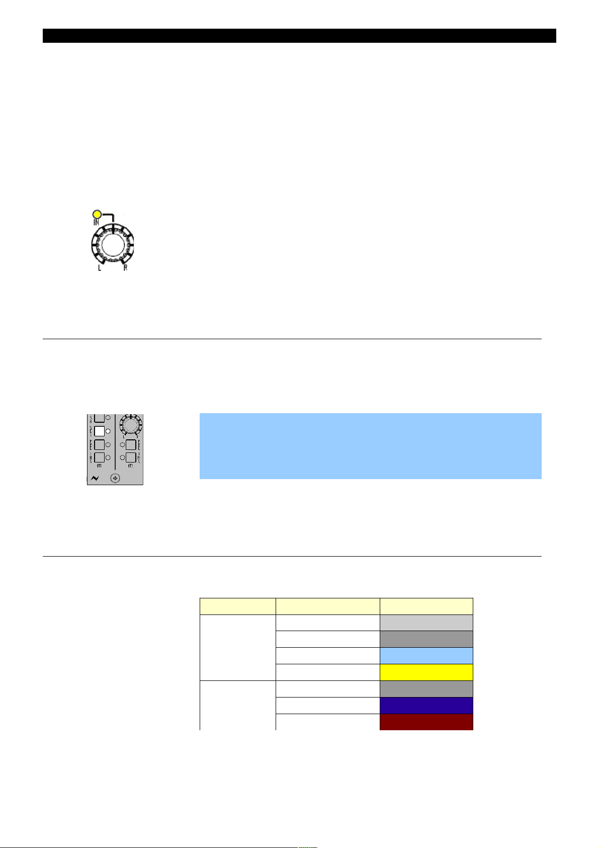
Console surface colour coding
The knobs and buttons on the Channel Strip and 8T sections of the
console are colour-coded for ease of operation.
Type Control Colour
Button
Channel Input Light Grey
Monitor Input Dark Grey
Auxiliary Light Blue
SEL Yellow
Rotary
Level Control Dark Grey
Pan Dark Blue
Gain Dark Red
- 16 -

Abbreviations & Acronyms
8T 8 Track PSU Power Supply Unit
AFL After Fader Listen RET Return
CAL Calibrate REV Reverb
CH Channel RTB Return Talkback
CHM Channel Mic S Sub
CRM Control Room Monitor SEL Select
DAW Digital Audio Workstation SIF Solo In Front
D-EXT Digital External(s) SIG Signal
DLN Digital Line(s) SND Send
DYN Dynamics SWP Swap
DMON Digital Monitor TB Talkback
EXT External(s) UTIL Utility
FNC Function SRC Sample Rate Converter
GR Gain Reduction RX/TX Receive/Transmit
HI Z High Impedance
HUI Human User Interface
I/L Interlock
IMR Insert Mix Return
INS Insert
INT Internal
ISO Isolate
LN Line
LS Loudspeaker
LS/RS Left Surround / Right Surround
M1 / M2 Stereo Monitor Loudspeakers 1 & 2
MON Monitor
MST Master
MTR Multi-track Recorder
ORD Order
PFL Pre Fade Listen
PLI Plug-Ins
- 17 -
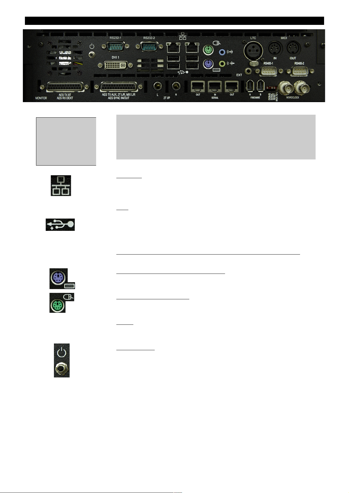
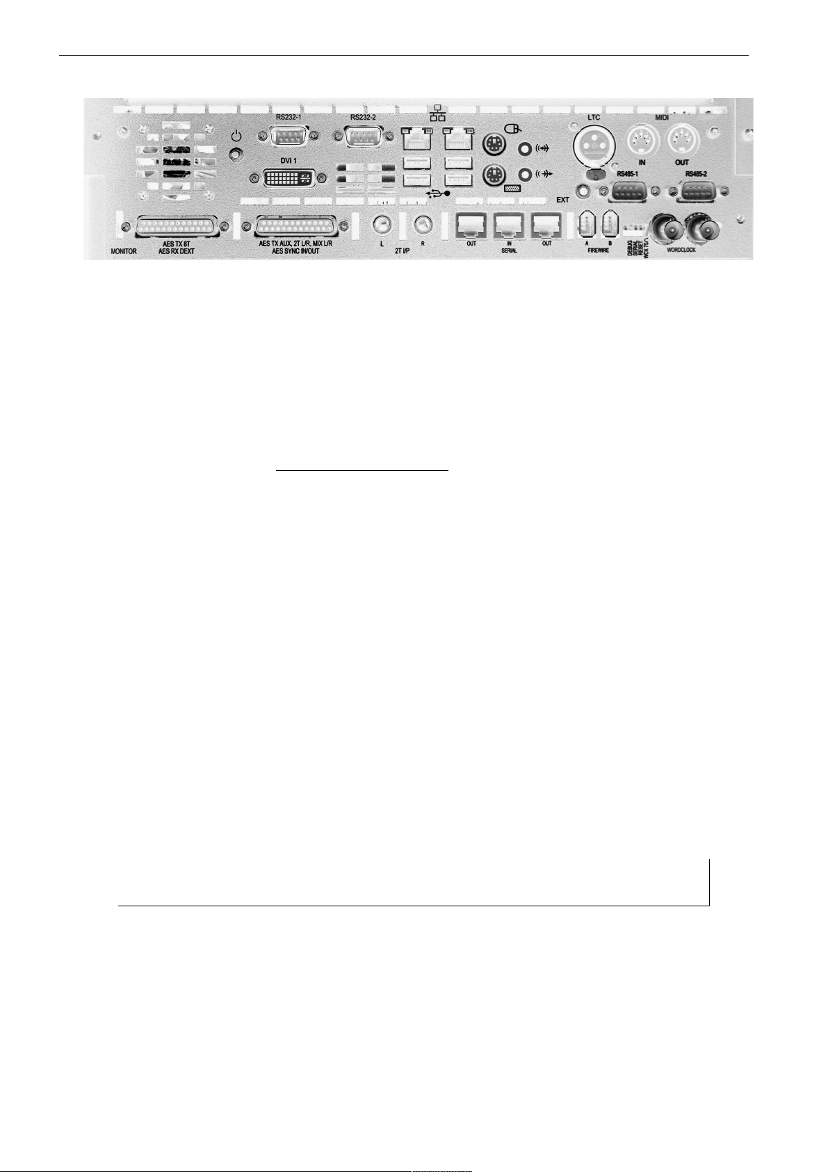
The Computer Cassette
IMPORTANT:
Before powering up the console, please connect an external monitor
screen to the DVI 1 connector. The console software cannot be used
without a screen connected.
Ethernet
Two standard Ethernet ports, used for internet connection to download
new software releases, remote diagnostics login and DAW control. The
left-hand port is port #1.
USB
Standard USB ports for connecting USB Flash drives for backing up and
recalling snapshots etc. An additional USB keyboard/mouse can also be
connected (Microsoft Windows compatible keyboard/mouse
recommended). There is also another USB port on the Master Meter panel
for ease of access.
MIDI In/Out, LTC , RS485-1/RS485-2, RS232-1/RS232-2, EXT
Not currently used.
External Keyboard (PS/2 connector)
A standard PS/2 keyboard can be connected here if required. The
connection should be made whilst the console is powered off.
Mouse (PS/2 connector)
The connector from the console trackpad is connected to this port. The
connection should be made whilst the console is powered off.
DVI 1
Provides the graphics output for use with an external monitor. A DVI-VGA
adaptor is supplied with the console for use with VGA external monitors.
Reset Button
Resets the computer without removing the power to the rest of the
console.
In addition there are 3 cables exiting the rear central section of
the console – HDMI for the DAW touch-screen display and 2 USB
connections, 1 for the touch-screen USB and 1 for the DAW
keyboard at the front of the console. All these cables should be
connected to the DAW computer being used – they are separate
from the Genesys computer system.
- 18 -
This computer cassette
has the optional
Monitor Section Digital
Board fitted. The
connectors on the
bottom row are for this
option.

IMPORTANT NOTICE
The Genesys Black computer cassette runs the Microsoft Windows 7
operating system (OS), and as such, the standard Power Up and Power
Down procedures should be observed just as they are with any other
computer system.
Important points to observe:
• To shut the computer down, or to turn off the console, you
Shutdown from within the Genesys software. Click System then
click Turn Off Console.
• Never turn the power switch on the rear of the meter bridge off
without first shutting the computer down correctly. Removing the
power in this manner will cause the computer to fail to boot-up
correctly the next time the console is powered up.
• Once the computer has been shut down and the external screen
goes blank, please wait for another 10 seconds before removing
the power to Genesys Black using the switch on the rear of the
meter bridge. This is because stopping the graphical output to the
screen is not the last thing that the computer does before shutting
down, it will continue to write files for a short while afterwards.
• Do NOT put the computer into Standby and then remove the
power. This will cause the computer to fail to boot-up correctly
the next time the console is powered on.
NB:
If for any reason, after several minutes, the Windows OS does not start
up you may see a message with the following option Start Normally... on
screen. Connect a Windows compatible keyboard to one of the USB
ports at the back of the computer cassette, select this option using the
arrow keys then press Enter. Otherwise, if this message is not onscreen, then power-cycle the console. The system will attempt to boot
up - make sure Start Normally is selected and press Enter. Finally
unplug the keyboard, and make sure a monitor is connected to DVI 1 for
normal operation.
After attempting the above, if you still cannot start the Windows OS
contact AMS Neve for technical assistance.
Failure to observe the correct Power Up and Power Down procedures may
invalidate the manufacturers warranty should the computer cassette
malfunction as a result.
- 19 -
Optional Console Hardware
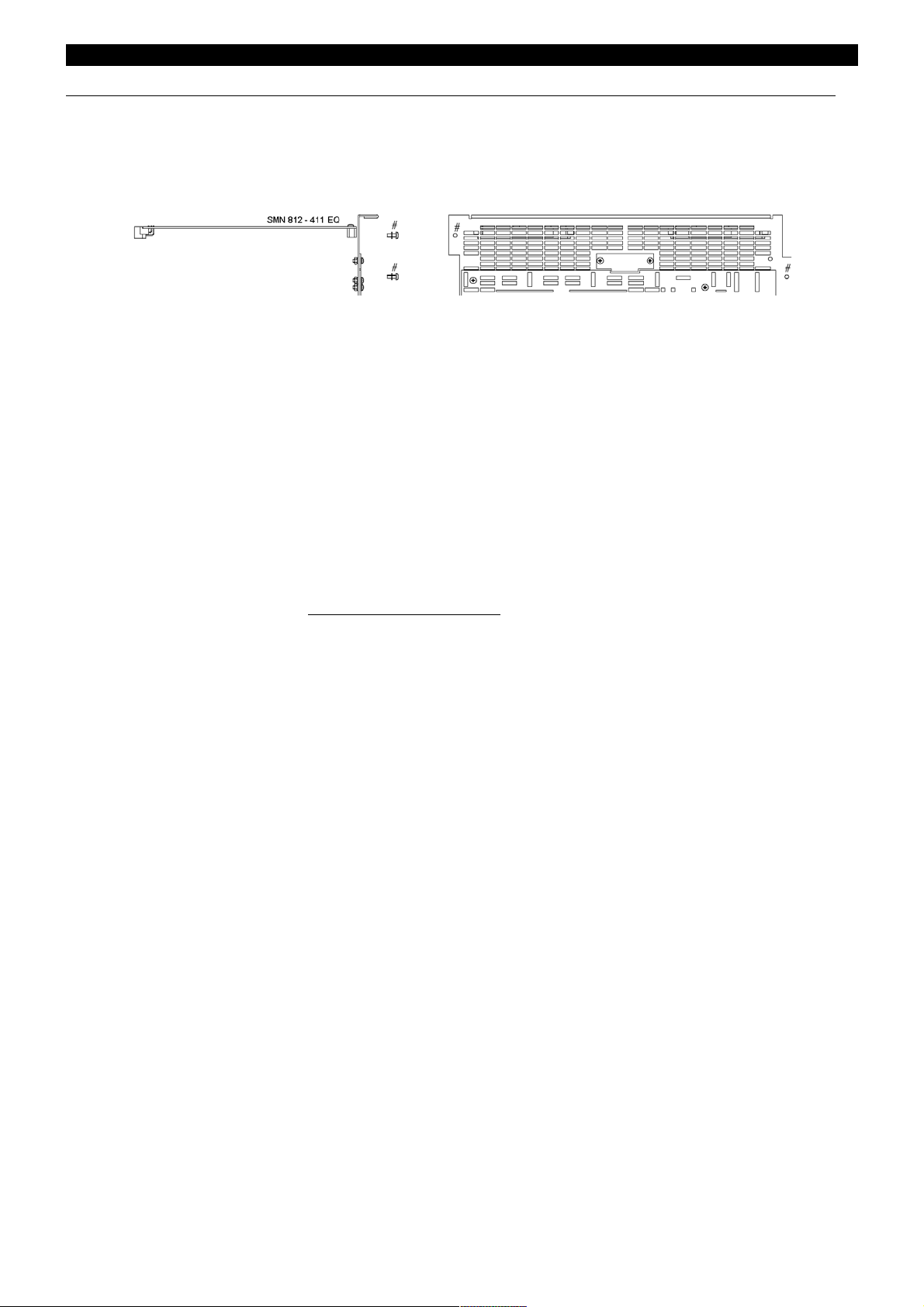
1084 EQ Cassette
(Part number SMN 812-411)
The assembly number is AM 5644.
This cassette provides 8 Channels with classic Neve 1084 EQ (3 bands per
channel).
Without this card (or the 88R EQ card), the EQ button (and LED) on each
channel strip will not function.
The EQ button on the Monitor Panel will not be locked out.
When the EQ cassette is present, the parameters are set using the four
encoders on the Monitor Panel.
The card itself has no external connectors – all connections are made
internally.
Installation Instructions
• Remove the power to the console.
• Ensure the switch settings have been set correctly for this card's
position. See Appendix A for the Switch Settings on page 226.
• Remove the entire ventilation facing plate on the rear of the console
by removing the two screws shown above.
• Slide the EQ cassette into the top-most slot and push it to the rear
until the connectors mate securely onto the backplane.
• Screw the faceplate back into place.
- 20 -
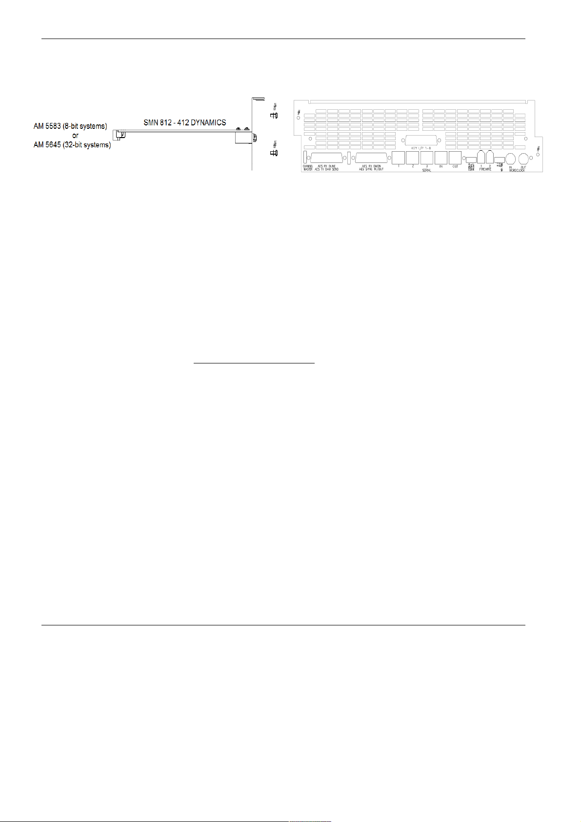
Dynamics Cassette
(Part number SMN 812–412)
The assembly number is AM 5645.
The Dynamics cassette provides 8 channels with Dynamics processing
(Compressor and Gate, including the provision of an external Key Input).
This external Key Input is available on both the Gate and Compressor.
Without this card, the DYN button (and LED) on each channel strip will
not function.
The DYN button under the on the Monitor Panel will also be locked out.
When the Dynamics cassette is present, the parameters are set using the
four encoders on the Monitor Panel.
Installation Instructions
• Remove the power to the console.
• Ensure the switch settings have been set correctly for this card's
position. See Appendix A for the Switch Settings on page 226.
• Remove the ventilation facing plate on the rear of the console, and
remove the Key Input blanking plate in the centre.
• Slide the Dynamics cassette into the middle slot and push the card
firmly to the rear until the connectors mate securely onto the
backplane.
• Screw the faceplate back into place, ensuring the Key Input D-type
connector and two adjacent pillars comfortably clear the faceplate
surface.
• Secure the Key Input D-type connector in place through the faceplate
using the pillars and two screws.
Operational Considerations
If you have an EQ processing cassette installed, it will only be possible to
place the EQ on the Channel path or the Monitor path on a channel, not
across both.
Likewise, the Compressor and Gate can only exist on the Channel or
Monitor path - it is not possible to have the Compressor on the Input and
the Gate on the Monitor path (or vice versa).
- 21 -
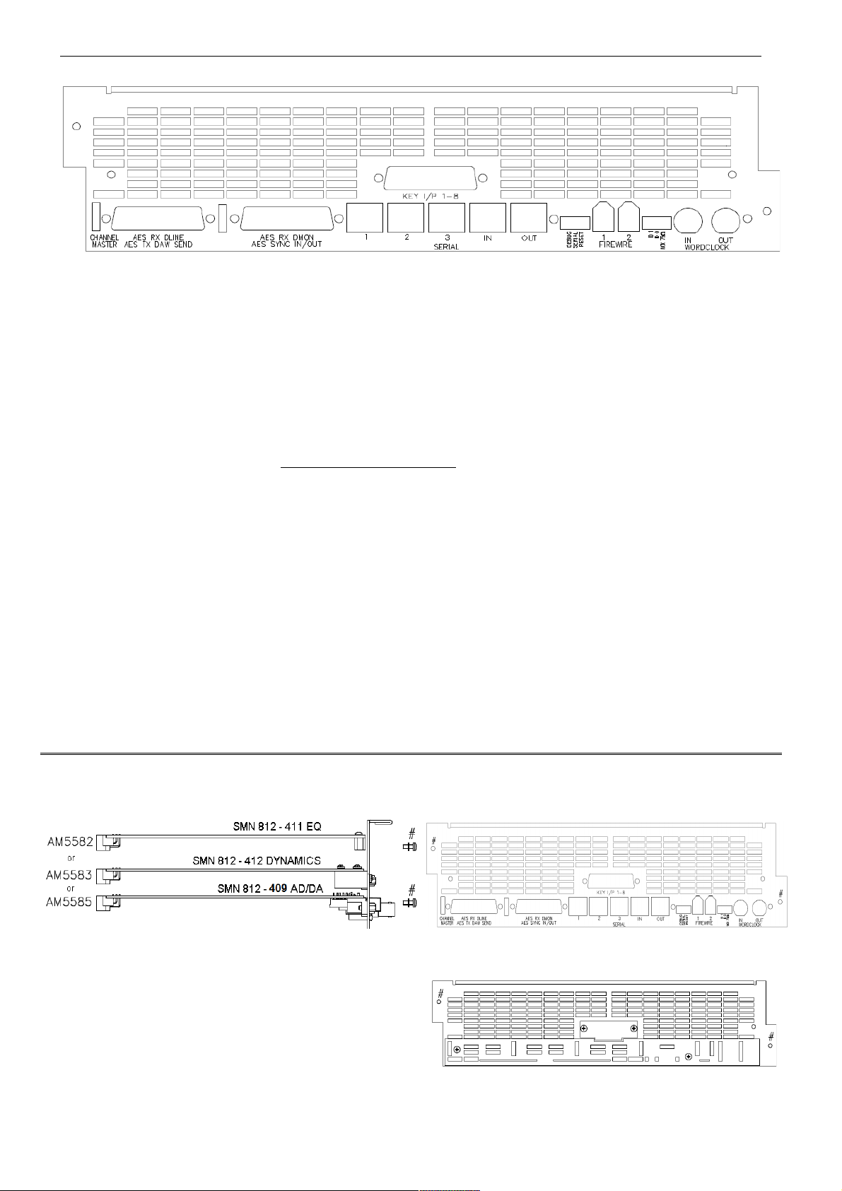
Channels Digital Converter System
(Part number SMN 812–409 Master and Slave)
This cassette provides 8 channels with AD/DA converters. Depending on
the digital channel requirements, a Master or Master and Slave card can
be installed in groups or individually.
Without this card, the DLN and DMON functionality (and leds) will not be
available on the console.
The digital converter board provides facility for Digital Line Inputs (DLN)
and digital DAW returns (DMON) into the desk plus enabling the Direct
Outputs on each channel to be sent digitally to the DAW.
Installation Instructions
• Remove the mains power cord from the console
• Remove the faceplate on the rear of the console (shown above) and
remove the connector blanking plate. If a new faceplate has been
provided, discard the one removed and use the new one.
• Slide the digital converter board upside down into the lowest slot and
push it to the rear until the connectors mate securely onto the
backplane.
• Screw the faceplate back into place (at points highlighted in red
above), ensuring all the connectors comfortably clear the faceplate.
• Secure all the connectors in place through the faceplate using the
included pillars and screws.
On larger consoles, it is possible to have one of each of the above cards for each block of 8 faders providing EQ,
Dynamics and digital lines/externals for the entire console.
For cards not initially present, the connector plates
on the console rear will be fitted with blank panels
instead.
- 22 -
Monitoring Digital Converter System
(Part number SMN 812–410)
This single card (regardless of console size), enables the Main Mix, 2T,
8T and Auxiliary Sends to be sent from the desk digitally, as well as
accepting a 5.1 Digital Surround External into the monitoring system
to be sent to the loudspeakers.
It is sub-fitted beneath the computer card and consists of 2 x 25-way Dtype connectors for AES, plus a FireWire connector as well as BNC
connectors for digital sync I/O. MADI connections are optional.
Installation Instructions
• Remove the mains power cord from the console.
• Unscrew the faceplate from the chassis at points A and B (above)
• Remove the computer card from the rear of the console. If a new
computer card has been provided, then return the one removed
and use the new one.
• Mount the digital converter board onto the faceplate of the computer
card using the included pillars and screws. Then slide the complete
assembly back into the cassette, until the connectors mate securely onto
the backplane.
• Screw the faceplate onto the chassis (highlighted in red above).
For more information on optional software & hardware,
please contact your local Neve distributor.
- 23 -
Touch-screen
The integrated touch-screen provides extended control for connected DAW
computers, allowing side-by-side integration of console and DAW so the
two can be used as one seamless system.
Connections
The touch-screen is connected to the DAW computer (Mac or PC) via USB.
For PC systems a USB3 cable should be used, and if the use of any
extenders or KVM systems is required they should support the USB3
standard. A USB3 cable is supplied with the console, and is one of the 3
cables exiting the centre section. For Mac systems, either USB2 or USB3
cables can be used.
Also from the centre section is a secondary USB cable which is a standard
USB2 extension cable from the 2 USB sockets on the front of the console
(underneath the front buffer/keyboard tray). This connection is provided
as a convenience to stop long cable runs being necessary, and to keep
cable numbers down.
Finally, there is an HDMI cable that should be connected to the video
output of the DAW computer. The touch-screen will then show the DAW
computer's display.
Note: It is also possible to show the Genesys Computer display on this
screen – to do this connect the DVI (or VGA with supplied adaptor) output
from the computer cassette to the additional DVI or VGA input on the rear
of the touch-screen (cable not supplied). Note that switching the
keyboard/mouse or touch-screen output to the Genesys Computer is not
supported, and a seperate keyboard/mouse is recommended if required.
Driver Installation (Mac)
No drivers are required for PC systems, as long as they are running
Windows 7 or newer.
For Mac systems the required driver may have been supplied with the
console. If not it can be obtained from AMS Neve by filling out a support
form online at http://ams-neve.com/support/console-fault-report
and stating that the Genesys Black touch-screen driver is needed.
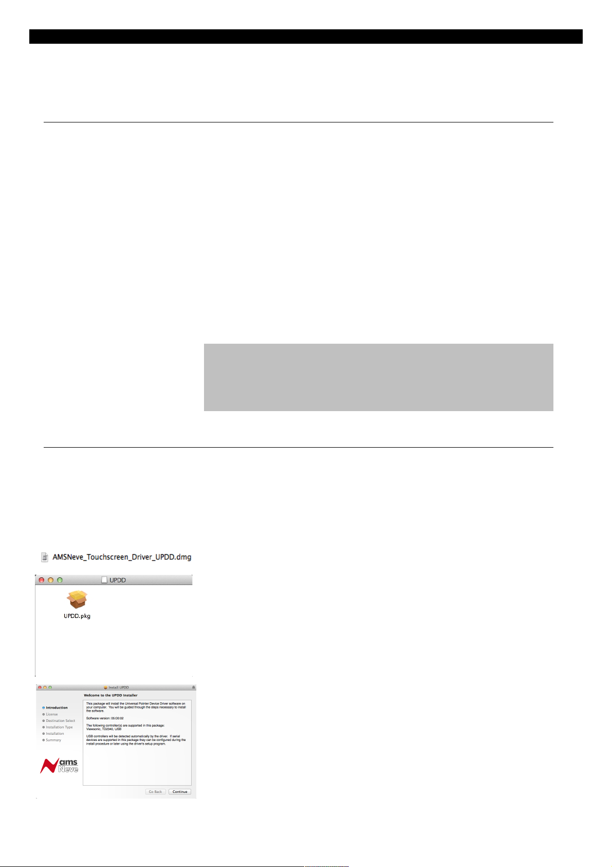
The file AMSNeve_Touchscreen_Driver_UPDD.dmg is the driver, and
should be double-clicked to mount the disk image.
Double-click UPDD.pkg to start the installation process.
The welcome screen will be displayed. Click Continue to move through
the installation process. The installer may require a password to
complete.
- 24 -
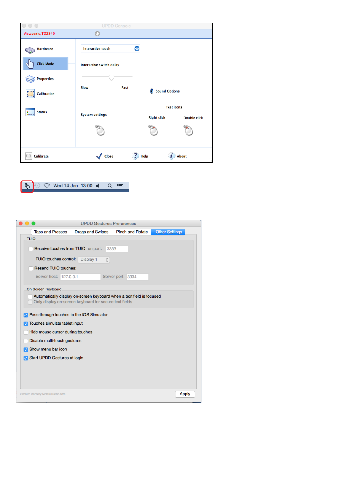
After the installation has
completed, the driver needs
to be configured:
u Open the UPDD
Console app (located in the
Utilities folder inside the
Applications folder).
u Set the configuration as
shown in the attached
image. (Click Mode set to
Interactive touch,
Interactive switch delay
set to about 65%).
u Click the Calibrate
button and follow the onscreen instructions.
u Click the Close button
when done.
u In the menu bar next to the clock at the top click on the
UPDD Gestures icon, then click on Settings. (If the icon is not
shown then from the Finder click Applications, then Utilities
and open the UPDD Gestures app).
u Click on Other Settings and
make sure the settings are set
as shown in the attached image
then click Apply.
The settings in the Taps and
Presses, Drags and Swipes,
Pinch and Rotate tabs can be
customised by the user to suit
their preferences.
When finished, close the window
by clicking on the red circle in
the top left of the window - do
not force close the window in
other way otherwise the
gestures app will shut down, the
icon will disappear and touchscreen activity may not be
recognised. If needed open the
UPDD Gestures by the method
above.
- 25 -

DAW Control
The following connections should be made between the Genesys Black
console and the DAW computer being used (eg. Apple Mac running Pro
Tools)
• HDMI cable for Genesys Black touch-screen DAW display
• 2x USB cables for touch-screen data and DAW keyboard
• Ethernet cable for DAW fader control (from Genesys computer)
NB:
When using hubs/switches, only standard Ethernet cables should
be used. When not using a hub and connecting the Genesys Black
computer directly to the DAW computer an Ethernet crossover
cable may be needed.
The following sub-sections will guide you through the steps to setup the
Genesys Black computer and your DAW computer for DAW control. (The
DAW computer operating systems shown below are Mac OS X, Windows
XP/Vista/7. The Genesys Black computer operating system is Windows 7.
Genesys Black Computer Settings for DAW Control
Windows 7 (Genesys Black Computer)
u From the Genesys Black software click System / Exit to
Windows to close the Genesys Black software (if the software is
running).
u The Windows taskbar may be hidden. It is located at the
bottom of the screen - move the mouse pointer to the bottom
of the screen and the taskbar should pop-up.
u On the taskbar click the Start Menu, select Control Panel (Small or
Large icons View) / Network Sharing Centre / Change adapter
settings / Local area Connection/ Properties. Select Internet
Protocol Version 4 (TCP/IPv4) from the list (make sure the tick box
remains selected) and click Properties.
When not using a hub/studio network and connecting the Genesys Black
computer directly to the DAW computer using a cross-over cable:
u Select Use the following IP address: and set your Genesys
Black to these settings:
• IP Address: 192 . 168 . 99 . 186
• Subnet Mask: 255 . 255 . 255 . 0
• Make sure the Default gateway / DNS settings are blank.
If a direct connection is not made, i.e. you are connecting via a router or
hub (through your studio/company network):
u Select Obtain an IP address automatically.
u Select Obtain DNS server address automatically.
u Click OK, close the Local Area Network/Control Panel windows and all
open windows.
u Finally from the desktop double-click the Genesys Applications icon
or from the Windows Start Menu click All Programs / Genesys
Applications / Genesys Applications.
u The Genesys software will now launch.
- 26 -

DAW Computer Settings
Mac OS X (DAW Computer)
u On your Mac DAW computer, from the Apple menu, select System
Preferences / Network. From the resulting screen;
When not using a hub/studio network and connecting the Genesys
computer directly to the DAW computer using a crossover cable:
u Select Ethernet 1 (or the primary/connected ethernet
connection) in the left hand window, and select Manually from
the pull-down menu next to Configure IPv4.
u Now set your DAW computer to these settings:
• IP Address: 192 . 168 . 99 . 183
• Subnet Mask: 255 . 255 . 255 . 0
• Make sure the Router setting is blank.
If a direct connection is not made, i.e. you are connecting via a router or
hub (through your studio/company network):
u Select Ethernet 1 (or the primary/connected ethernet
connection) in the left hand window, and select Using DHCP
from the pull-down menu next to Configure Ipv4.
u Finally click Apply and close the Network/System Preferences
windows.
Windows 7 (DAW Computer)
u On your Windows 7 DAW computer, from the Start Menu, select
Control Panel (Small or Large icons View) / Network Sharing Centre /
Change adapter settings / Local area Connection/ Properties.
Select Internet Protocol Version 4 (TCP/IPv4) from the list (make
sure the tick box remains selected) and click Properties.
When not using a hub/studio network and connecting the Genesys
computer directly to the DAW computer using a cross-over cable:
u Select Use the following IP address: and set your DAW
computer to these settings:
• IP Address: 192 . 168 . 99 . 183
• Subnet Mask: 255 . 255 . 255 . 0
• Make sure the Default gateway / DNS settings are blank.
If a direct connection is not made, i.e. you are connecting via a router or
hub (through your studio/company network):
u Select Obtain an IP address automatically.
u Select Obtain DNS server address automatically.
u Finally click OK and close the Local Area Network/Control Panel
windows.
Windows XP (DAW Computer)
u On your Windows XP DAW computer, from the Start Menu, select
Control Panel (Classic View) / Network Connections / Local Area
Connection / Properties. Select Internet Protocol (TCP/IP) from
the list (make sure the tick box remains selected) and click Properties.
When not using a hub/studio network and connecting the Genesys
- 27 -

computer directly to the DAW computer using a cross-over cable:
u Select Use the following IP address: and set your DAW
computer to these settings:
• IP Address: 192 . 168 . 99 . 183
• Subnet Mask: 255 . 255 . 255 . 0
• Make sure the Default gateway / DNS settings are blank.
If a direct connection is not made, i.e. you are connecting via a router or
hub (through your studio/company network):
u Select Obtain an IP address automatically.
u Select Obtain DNS server address automatically.
u Finally click OK and close the Local Area Network/Control Panel
windows.
Windows Vista (DAW Computer)
u On your Windows Vista DAW computer, from the Start Menu, select
Control Panel (Category View) / Network and Internet / Network
Sharing Centre / Manage network connections / Local area
Connection / Properties. Select Internet Protocol Version 4
(TCP/IPv4) from the list (make sure the tick box remains selected) and
click Properties.
When not using a hub/studio network and connecting the Genesys
computer directly to the DAW computer using a cross-over cable:
u Select Use the following IP address: and set your DAW
computer to these settings:
• IP Address: 192 . 168 . 99 . 183
• Subnet Mask: 255 . 255 . 255 . 0
• Make sure the Default gateway / DNS settings are blank.
If a direct connection is not made, i.e. you are connecting via a router or
hub (through your studio/company network):
u Select Obtain an IP address automatically.
u Select Obtain DNS server address automatically.
u Finally click OK and close the Local Area Network/Control Panel
windows.
DAW Control over Ethernet Driver - ipMIDI
With the hardware configured and the IP addresses set, then the only
remaining things that need to be done are to download the ipMIDI driver
from www.nerds.de (and install the touch-screen driver for the DAW (if
using Mac).
This is a 3rd party driver that allows communication data to be sent
between the Genesys Black and the DAW computer.
This driver only needs to be installed on your DAW computer (not the
Genesys computer). There will be two available, one for Windows and one
for Mac OS X. The Mac OS X driver is fully functional and free to
download. The Windows driver is a trial version and works for 60 minutes
after its first use. After every reboot, it will work again for an additional 60
minutes. You can purchase the fully functional version from the
www.nerds.de website.
- 28 -
u Download and install the one applicable to your DAW system.
After installation the driver needs to be set up correctly. Below are
instructions showing you how to do this for both OS X and Windows
Vista/7.
Windows Vista / 7 (DAW Computer)
u Close all open applications and windows including all DAW programs.
u From the Windows Start Menu select All Programs/ipMIDI -
Ethernet MIDI Port/ipMIDI Monitor.
u The ipMIDI window should pop-up, if not then repeat the above step.
u From the ipMIDI window set the Ports After Reboot to 20, make
sure Loop back is unticked and finally click Mute None.
u If you are logged into Windows with Administrator privileges then click
OK to apply the changes (Change button will be disabled in this case),
otherwise click Change then click OK.
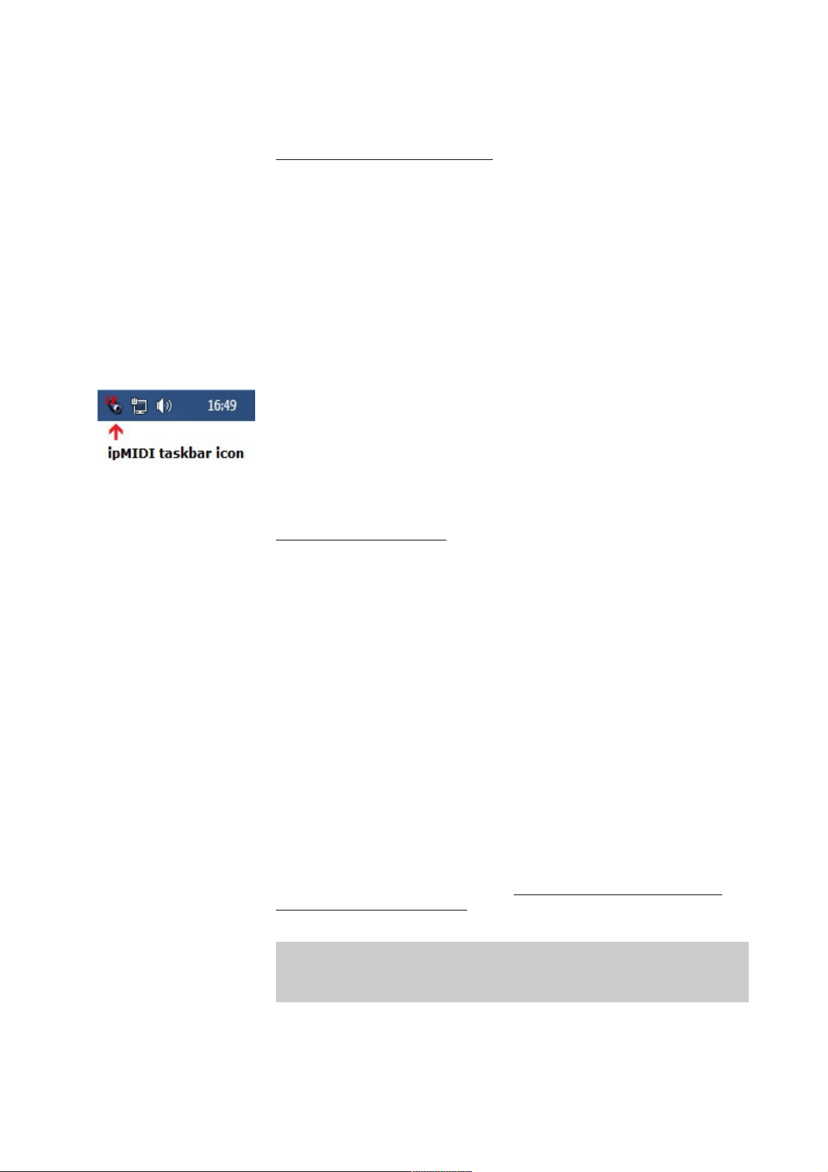
u Finally reboot your DAW computer to apply the changes and make sure
when Windows starts-up the ipMIDI icon is shown in the Windows
taskbar at the bottom right of the screen next to the clock and other
taskbar icons. If this not the case then start the ipMIDI program from the
Windows Start Menu as shown above in the first two steps (once opened
do not close the window – you may have to repeat this step on each
reboot of your DAW computer).
Mac OS X (DAW Computer)
u Close all open applications and windows including all DAW programs.
u On your Mac DAW computer, from a new Finder window, select
Applications / Utilities and open the Audio MIDI Setup app.
u If the MIDI Studio window is not shown but instead you see the
Audio Devices window then from the menu bar at the top of the screen
select Window / Show MIDI Window.
u The MIDI Studio window should pop-up, if not then repeat the above
step. Next scroll through the list of devices and open ipMIDI.
u From the ipMIDI Setup window set the Number of Ports to 20 and
make sure Loop Back is unticked.
u Click OK to apply the changes.
u Finally reboot your DAW computer to apply the changes.
FOR TOUCH-SCREEN DRIVER INSTALLATION ON MAC SYSTEMS
PLEASE REFER TO THE SEPERATE MAC TOUCH-SCREEN DRIVER
INSTALLATION DOCUMENT AVAILABLE FROM AMS NEVE SUPPORT
Once the above setup for DAW control (ethernet connection - direct or
hub, IP addresses, and driver settings) is completed you are ready for
DAW control. See the chapters on Pro Tools, Apple Logic,
Nuendo/Cubase etc. for more.
- 29 -

Modules Overview
None of the Genesys modules contain any user serviceable parts, and
should they develop a fault, they will always need returning to AMS Neve
for repair (or to one of our officially nominated Service Centres).
Channel Input Module
These modules do not have any addressable switches, and can be freely
swapped to any other Channel position on the console.
Rev Return Module
These modules do not have any addressable switches, but they cannot be
swapped to any other Rev Return position on the console.
Dynamics Cassettes/EQ Cassettes/AD/DA Cassettes/Channel Meter panel
All of these can be swapped between different 8-fader sections of the
desk, but an address switchblock on each card needs to be set to reflect
its position on the desk.
Please see Appendix A on page 226 for a table these switch settings.
Console Hardware Considerations
Removing Modules
u Firstly, ensure the computer has been shut down correctly and the
power has been removed from the console.
u Remove the console-wide thin metal strip attached to the bottom of
the meter strip that also keeps the channel modules securely in place.
The modules cannot be removed while this is in place.
u Remove the two screws on the module you wish to remove, one each
at the top and bottom of the module. Also check any connectors at the
rear of the module are removed (e.g. Mic/Line)
u Screw the two module extraction tools into the top and bottom of the
module. These are two black plastic rods (about 10cms in length) that
have been supplied with your console (part number 727-013).
u Apply even pressure to both extraction tools and pull the module
gently upwards from the console, taking care not to catch it on the
adjacent modules.
Inserting Modules
u Firstly, ensure the computer has been shut down correctly and the
power has been removed from the console.
u Guide the bottom module edge between the two runners at the bottom
of the module.
u Slowly slide the module into the console, taking care not to catch the
edges on any of the adjacent modules.
When inserting modules into the console chassis, care must be taken so
that equal pressure is applied the whole length of the module, rather than
just applying pressure to each end of the module.
u When the back of the module reaches the backplane, apply a slow,
even pressure to the entire length of the module.
This will ensure that a good contact is made between the module and the
audio busses on the backplane responsible for the audio.
- 30 -
Modules should never be
removed or inserted with the
power on.
Only when the computer has
been shut down correctly
and the power has been
removed, should modules be
inserted into (or removed
from) the console.
 Loading...