

Neve Genesys User Manual

NEVE
NEVENEVE
NEVE
GENESYS
User Manual
Issue 1
527 - 384
GENESYS User Manual Issue 1
Health & Safety Notice
FOR YOUR OWN SAFETY AND THE PROTECTION OF OTHERS,
PLEASE OBSERVE THE FOLLOWING SAFETY HEALTH AND SAFETY INSTRUCTIONS
[ READ THESE INSTRUCTIONS AND KEEP THEM HANDY
[ HEED ALL SAFETY WARNINGS
[ DO NOT USE NEAR WATER
[ CLEAN ONLY WITH A DRY CLOTH
[ DO NOT INSTALL NEAR HEAT SOURCES
[ DO NOT BLOCK VENTILATION OPENINGS
[ PROTECT THE POWER CORD
[ USE ONLY ACCESSORIES SPECIFIED BY THE MANUFACTURER
[ UNPLUG WHEN UNUSED FOR LONG PERIODS OF TIME
[ MODULES AND CARDS SHOULD NOT BE INSERTED OR REMOVED WITH THE POWER ON
[ REFER ALL SERVICING TO QUALIFIED PERSONNEL ONLY
[ NO USER SERVICEABLE PARTS INSIDE
FAILURE TO FOLLOW THESE PROCEDURES AND RECOMMENDATIONS
COULD INVALIDATE THE MANUFACTURER'S WARRANTY
- 2 -
GENESYS User Manual Issue 1
Console Overview
• Six Auxes 4 Mono and two stereo
• stereo mix buss
• Two stereo monitoring speaker sets
• Two 5.1 monitoring speaker sets
• 16 channels of Neve mic/line amplifiers
• 16 channels of DAW monitoring
• 8 Groups
• 1 Main output
• 4 stereo effects returns
• 16 Channel, 8 Track or 2 Track metering
• 2 Cue mixes
• Full talkback capability
• Internal power supply units
• Expandable to 64 channels, either in straight or wedge formation
• USB flash drive for Store, Load & Reset functionality
• Hands-on DAW control for Pro Tools, Logic, Nuendo & more
• Full console instant Reset
• Digitally controlled EQ and Dynamics (1084 EQ circuitry and 88R style Dynamics)
• Motorised 8T and Main Output faders with DAW control
• Optional Recall module so all rotary control positions can be stored and reset
• Optional EQ / Dynamics cassettes (8 per card)
• Optional AD/DA cassette to provide digital Ins/Outs (8 per card)
• Optional Digital Monitoring cassette providing I/O for Aux, 8T, Main Mix and monitoring
- 3 -

GENESYS User Manual Issue 1
Introduction to GENESYS
For more than 40 years, the designers and engineers at Neve have worked uncompromisingly to produce
the world's premier audio recording and mixing equipment. As a result, Neve products have long
exceeded the most stringent requirements for sound quality and musicality – from countless classic
albums to the vast majority of each year's blockbuster films. Traditionally, such perfection has come at a
price, meaning that only the largest and most prestigious studios could own a Neve recording console.
Until now.
Introducing GENESYS.
A hand-built expandable analogue recording console with digital workstation control. A console that builds
upon Neve's forty years of technical heritage, including legendary mic pre-amplifiers and highly revered
analogue circuit design.
GENESYS also accommodates for the seismic changes in methods of music recording, with extensive
digital control and connectivity.
In any configuration, GENESYS offers an excellent studio control surface with comprehensive monitoring
and signal routing compatibilities. This eliminates the typical collection of awkwardly interfaced devices,
and puts a proper console back in the heart of the studio.
As with all Neve products, GENESYS offers sound and build quality beyond reproach. Even the console
stand was developed in conjunction with internationally renowned studio designer Roger D'Arcy of
Recording Architecture in London.
With GENESYS, the widest possible range of studios can legitimately claim to be a Neve facility.
The future begins here.
Head Office:
AMS Neve
Billington Road
Burnley
Lancashire
England
BB11 5UB
Phone: +44 (0) 1282 417 011
Fax: +44 (0) 1282 417 282
London Office:
+44 (0) 2074 323 858
Email: Info@AMS-Neve.com
Web: www.AMS-Neve.com
© ® 2008 AMS Neve Ltd own the copyright of all information and figures contained in this manual which are not to be copied or
reproduced by any means or disclosed in part or whole to any third party without written permission.
As part of our policy of continual product improvement, we reserve the right to alter specifications without notice but with due regard to
all current legislation.
Disclaimer: The information in this manual has been carefully checked and is believed to be accurate at the time of publication.
However, no responsibility is taken by AMS-Neve for inaccuracies, errors or omissions nor any liability assumed for any loss or damage
resulting either directly or indirectly from use of the information contained within.
Trademarks: All trademarks are the property of their respective owners and are hereby acknowledged.
- 4 -

GENESYS User Manual Issue 1
Table of Contents
Health & Safety Notice...........................................2
Console Overview..................................................3
Introduction to GENESYS.......................................4
About this manual..................................................9
Conventions used.............................................9
Console surface colour coding............................9
Abbreviations & Acronyms...............................10
The Computer Cassette........................................11
OLD style (inc Automation option).........................11
NEW Style..........................................................12
Optional Console Hardware..................................13
EQ Cassette...................................................13
Dynamics Cassette.........................................13
Channels AD/DA Cassette................................14
Operational Considerations..............................14
Digital Monitoring Cassette..............................15
Optional Console Software...................................16
Automation....................................................16
Recall............................................................16
Wiring connections / Setup for HUI control
OLD type computer.............................................17
NEW type computer............................................18
Powering Procedure
Switch On Procedure...........................................18
Power-down Procedure........................................18
SEL Mode.............................................................19
Channel Sel Mode...........................................19
Monitor SEL Mode...........................................19
GENESYS Application Scenarios...........................20
Recording......................................................20
Mixing...........................................................21
Live Recording................................................22
Hui Control of DAW (inc Sub-mixing).................23
Channel Strip
CHANNEL Section
+48v.................................................................24
HI Z..................................................................24
PAD...................................................................24
Ø......................................................................24
90Hz filter..........................................................24
INPUT TRIM........................................................24
L/R....................................................................24
PROCESSING Section
ORD..................................................................25
SEL Mode on the PROCESSING section
To enter and exit SEL Mode on the Channel Strip.. ..25
To allocate processing elements across Channel and
Monitor paths.....................................................25
To set the order of processing on the Channel and
Monitor paths.....................................................25
AUXES Section
Master Level.......................................................26
>8T buttons.......................................................26
SEL Mode on the AUXES Section
To Set How the Channel and Monitor paths feed the
Auxes................................................................26
DIRECT OUTPUT Section
Master Level.......................................................27
MONITOR Section
L / R Pan............................................................28
Mon Level Control...............................................28
AUT led..............................................................28
DAW..................................................................28
I/P 2..................................................................28
CH....................................................................28
ISO...................................................................28
D-MON led.........................................................28
SEL...................................................................29
>8T...................................................................29
SWP..................................................................29
SOLO.................................................................29
CUT...................................................................29
TO MON leds......................................................29
Preventing feedback loops
REVERB RETURNS / AUX MASTERS Section
REV Return Section
TO CUE..............................................................31
WIDTH...............................................................31
PAN / BAL..........................................................31
MONO................................................................31
ON....................................................................31
ISO...................................................................31
AFL...................................................................31
SEL Mode on the REV RETURN Section
To set how the Rev Returns feed the Cues..............32
AUX MASTERS Section
Master Send.......................................................33
MIX Section
IMR...................................................................33
PRE...................................................................33
INS...................................................................33
HEADPHONES Section
Master Send.......................................................33
8T AUXES Section
ISO...................................................................34
SEL...................................................................34
INS...................................................................34
PRE...................................................................34
SEL Mode on the 8T AUXES Section
To set which Auxes are fed by the 8Ts....................35
TONE / RTB Section
SIG PRES...........................................................36
RTB...................................................................36
OSC LEVEL.........................................................36
CH....................................................................36
8T.....................................................................36
2T/MIX..............................................................36
- 5 -

GENESYS User Manual Issue 1
LS.....................................................................37
OSC FRQ............................................................37
METERS Section
CH MTRS...........................................................37
CH I/P...........................................................37
DAW SND......................................................37
DAW RET.......................................................37
8T MTRS............................................................37
8T................................................................37
AUX..............................................................37
EXT...............................................................37
CRM..............................................................37
2T MTRS............................................................38
MIX...............................................................38
CRM..............................................................38
2T................................................................38
CUE 1 / 2.......................................................38
MASTER SEL Section
LOCK.................................................................39
MIC...................................................................39
LN.....................................................................39
DAW..................................................................39
DLN led.............................................................39
SWP..................................................................39
MIX...................................................................39
CH SAFE............................................................40
MON SAFE..........................................................40
I/L....................................................................40
LATCH...............................................................40
RESET...............................................................40
LINK..................................................................40
DAW SND...........................................................41
DAW RET...........................................................41
I/P 2 & D-MON led..............................................41
ROUTE SEL Section
FILING...............................................................42
LOAD.................................................................42
SAVE.................................................................42
ROUTE SEL Section
RTE SEL.............................................................42
1 – 8.................................................................42
L & R.................................................................42
CH....................................................................43
MON..................................................................43
& keys........................................................43
CUE MIX Section
EXT 1-4.............................................................44
UTIL..................................................................44
AUX 1-6.............................................................44
TILT EQ.............................................................44
BAL...................................................................44
LEVEL................................................................44
SEL Mode on the CUE MIX Section
To select the Aux feeding the Cue.........................45
To set the Utility path feeding into the Cue.............45
CONTROL ROOM MONITOR Section
AUX 1 – 6..........................................................46
CUE 1 & CUE 2...................................................46
MIX...................................................................46
8T.....................................................................46
2T.....................................................................46
EXT 1 & EXT 2....................................................46
EXT 3 & EXT 4....................................................47
D-EXT led..........................................................47
INT...................................................................47
EXT...................................................................47
SUM..................................................................47
INS...................................................................47
ST (or Downmix).................................................47
ØL.....................................................................47
AFL/PFL led........................................................48
PFL....................................................................48
SIF....................................................................48
M2 SEL..............................................................48
SWP..................................................................48
A, B, M1 & M2....................................................48
S & LS/RS leds...................................................48
LS SOLO led.......................................................49
L / C / R / LS / S / RS..........................................49
Master CUT........................................................49
DIM...................................................................49
MONO................................................................49
Main Monitor Pot.................................................49
SEL Mode on the CONTROL ROOM MONITOR Section
To enter and exit SEL Mode..................................50
To tie a set of speakers to the Stereo Downmix.......51
To lock relative levels within a loudspeaker set........51
To lock the S and LS/RS to sets of loudspeakers......51
To Route 8T Outputs to specific loudspeakers..........52
2T.....................................................................52
TALKBACK Section
CUE 1 & CUE 2...................................................53
SLATE................................................................53
TB.....................................................................53
TB ALL...............................................................53
RED LIGHT.........................................................54
DAW / CONSOLE CONTROL Screen
EQ....................................................................55
DYN..................................................................55
2T Operation......................................................56
5.1 Mixing Mode.............................................56
Group Mixing Mode.........................................56
F1 – F5 .............................................................57
DAW..................................................................57
AUX...................................................................57
PANS.................................................................57
PLI....................................................................58
FADS.................................................................58
AUTO.................................................................58
CHAN................................................................58
BANKS...............................................................58
& keys........................................................58
Faders & Keypad
Master Faders
Channel Faders
CUT...................................................................59
SOLO.................................................................59
Alpha Display.....................................................59
8T Faders
CUT / SOLO........................................................59
Alpha Display.....................................................59
MAIN MIX Fader
- 6 -

GENESYS User Manual Issue 1
TRANSPORT Keys
MASTER AUTOMATION buttons
KEYPAD
Meterbridge
CHANNEL Meters
MIX...................................................................61
MTR..................................................................61
8T 1 to 8T 8 leds.................................................61
SIG...................................................................61
GR....................................................................61
REV RETURN Meters
MIX L/R.............................................................61
8T SIG...............................................................61
MASTER METER Section
DAW..................................................................62
SOLO.................................................................62
USB..................................................................62
Talkback Mic.......................................................62
VU....................................................................62
PPM...................................................................62
SET...................................................................62
PEAK.................................................................62
P/HOLD.............................................................62
DAW..................................................................63
PSU STATUS.......................................................63
Master Screen
EQ
DYN
Compressor........................................................66
Local Mode....................................................66
Global Mode...................................................66
Gate/Expander...................................................67
2 TRK
Group Mode.......................................................68
5.1 Mode...........................................................68
DAW
Settings
LS Settings........................................................70
8T To Mon......................................................70
Sub To Down-mix...........................................70
5.1 Mono.......................................................70
LS SOLO........................................................70
SUB..............................................................70
Down-Mix To..................................................70
Sub Speaker Locks.........................................71
LS/RS Speaker Locks......................................71
Speaker Trims................................................71
8T Solo Linking...................................................71
Destruct........................................................71
Safe..............................................................71
Power Up...........................................................71
Default..........................................................71
As Was..........................................................71
Last Store Made.............................................71
Custom Store.................................................72
Software Updates................................................72
Desk Designer....................................................72
Tie Ch Sel..........................................................73
Sel Route.......................................................73
DYN..............................................................73
EQ................................................................73
Last One Used................................................73
OSC..................................................................73
Osc with Slate................................................73
Osc to 2T.......................................................73
Setups...............................................................73
Set by Reset..................................................73
Calibrate............................................................73
FILING
Load..................................................................75
Save..................................................................75
Copy.................................................................75
Delete...............................................................76
RTE
ENCORE
SYSTEM
Reboot...............................................................77
Restart PC..........................................................77
Shutdown PC......................................................77
Audio Monitoring Boards
Monitor Board 1 (Cue mix)...................................78
Monitor Board 2 (M1 L/S )....................................78
Monitor Board 3 (Mix Insert).................................79
Monitor Board 4 (Mix Output)...............................80
Monitor Board 5 (Rev Return 4)............................80
Monitor Boards 6, 7 & 8 (Rev Returns 3, 2 & 1).......80
GENESYS Physical Information
Dimensions........................................................81
Connector Types.................................................81
Console Connector pin-outs
Computer Cassette
USB...................................................................82
Mouse...............................................................82
Keyboard...........................................................82
RJ 45.................................................................82
Timecode...........................................................83
RS 232..............................................................83
VGA..................................................................83
Monitor Section Connectors
Monitor External Inputs 1 & 3...............................84
Monitor External Inputs 2 & 4...............................84
Loudspeaker Outputs A & M1................................85
Loudspeaker Outputs B & M2................................85
Monitor Insert Send.............................................86
Monitor Insert Return..........................................86
Console Outputs – 8Ts.........................................87
Console Outputs - Auxiliaries................................87
8T Insert Send....................................................88
8T Insert Return.................................................88
Channel Section Connectors
I/P2 Tape Monitor Send........................................89
I/P2 Tape Monitor Return.....................................89
DAW Send..........................................................90
- 7 -

GENESYS User Manual Issue 1
DAW Return.......................................................90
Channel Insert 2 Send.........................................91
Channel Insert 2 Return.......................................91
Channel Insert 1 Send.........................................92
Channel Insert 1 Return.......................................92
Optional AES Monitoring cassette, SMN 812 – 410
Firewire A..........................................................93
Firewire B..........................................................93
Socket 1............................................................93
Socket 2............................................................94
Socket 3............................................................94
Optional AES Channels cassette, SMN 812 – 409
Socket 1............................................................95
Socket 2............................................................95
Socket 3............................................................95
Optional Dynamics Cassette, SMN 812 – 412
Key Input...........................................................96
General Fuses – Ratings & Location
Appendix A – Processing Cassettes Switch Settings
Board ID............................................................98
Printing this Manual...........................................102
- 8 -
GENESYS User Manual Issue 1
About this manual
This manual consists of:
• A section-by-section operational overview of all parts of the console surface
• Technical & physical specifications including power consumption, dimensions, weight and other
relevant information
• Section on the optional Automation system
• Section on the optional Recall software
• Schematics and reference drawings of D-Type pin-outs etc.
There is a Heading Index at the start of this manual, plus an Alphabetical Index, an Illustration Index and
an Index of Tables at the end.
There is also a table explaining the Acronyms and Abbreviations of the most commonly used buttons and
functions in this document.
Some controls on the console have two functions (for example a rotary Pot provides a rotary
control, plus an On/Off push-switch to either enable the feature or provide a second
function).
Where relevant, the On/Off state (or second function) of the control is displayed by an
adjacent led.
Conventions used
All button names / rotary controls are shown in BOLD CAPITALS.
Any text regarding the interlocking of buttons is shown in plain Italics.
All text regarding the optional audio processing cassettes is framed.
> An arrow-shaped bullet-point indicates you should do this action.
All text regarding SEL Mode is shown with a blue background.
All diagrams illustrating SEL Mode functionality, will have unavailable functions and leds
greyed out (left).
Console surface colour coding
The knobs and buttons on the Channel Strip and 8T sections of the console are colour-coded for
ease of operation.
Type Control Colour
Button
Channel Input Light Grey
Monitor Input Dark Grey
Auxiliary Light Blue
SEL Yellow
Rotary
Level Control Dark Grey
Pan Dark Blue
Gain Dark Red
- 9 -

GENESYS User Manual Issue 1
Abbreviations & Acronyms
8T 8 Track PSU Power Supply Unit
AFL After Fader Listen RET Return
CAL Calibrate REV Reverb
CH Channel RTB Return Talkback
CHM Channel Mic S Sub
CRM Control Room Monitor SEL Select
DAW Digital Audio Workstation SIF Solo In Front
D-EXT Digital External(s) SIG Signal
DLN Digital Line(s) SND Send
DYN Dynamics SWP Swap
D-MON Digital Monitor TB Talkback
EXT External(s) UTIL Utility
FNC Function
GR Gain Reduction
HI Z High Impedance
I/L Interlock
IMR Insert Mix Return
INS Insert
INT Internal
ISO Isolate
LN Line
LS Loudspeaker
LS/RS Left Surround / Right Surround
M1 / M2 Stereo Monitor Loudspeakers 1 & 2
MON Monitor
MST Master
MTR Multitrack Recorder
ORD Order
PFL Pre Fade Listen
PLI Plug Ins
- 10 -
GENESYS User Manual Issue 1
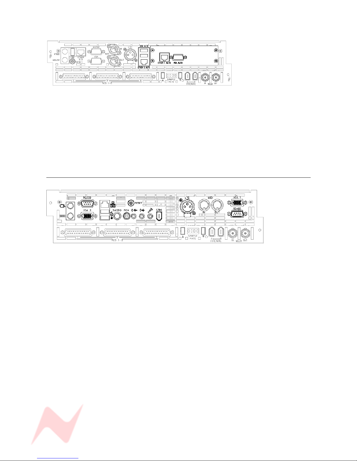
The Computer Cassette
The console does not need an external PC to run, but comes fitted with a
single on-board PC cassette that provides these connectors and functions:
There are two types of computer cassette which can be fitted, referred to
as the Old style or New style.
OLD style (inc Automation option)
Ethernet STD
Standard Ethernet port.
RS 232
Typically used for controlling external mic modules, for example the Neve
1081s.
USB
For backing up and recalling Automation files, Recall files, Desk Setups etc
to a USB device. There is another USB port on the meter bridge for ease
of access.
MIDI In/Out
Provides 8 Channels of Midi communication.
External Keyboard
If more functionality is required than the fitted keyboard provides, an
external keyboard can be used instead.
Mouse
An external mouse or trackball can be used instead of the console Glide
Pad/Buttons.
Timecode In
If the console does not have the Automation option fitted, this ensures the
screen can display an external timecode source as it runs.
If the Automation option is fitted, it is this timeline that automation events
are written against.
With regard to timecode, the console only ever acts as a slave.
With the exception of the USB port, all of these connectors are accessed
from the rear of the console.
- 11 -
GENESYS User Manual Issue 1
With the Automation option fitted, additional connectors become available.
Ethernet 1 Auto & Ethernet 2 Auto
Used for HUI control & communication.
Ether 1 Auto is used to connect to a DAW and provide Midi over Ethernet
communication so HUI control is possible.
VGA Auto
An external VGA monitor can be attached so the console controls and
Encore Plus Automation screen can be accessed.
NEW Style
All these connectors have the same function as described above, except
for:
VGA 1
Provides the graphics output from this card (VGA 2 is not used).
- 12 -
GENESYS User Manual Issue 1
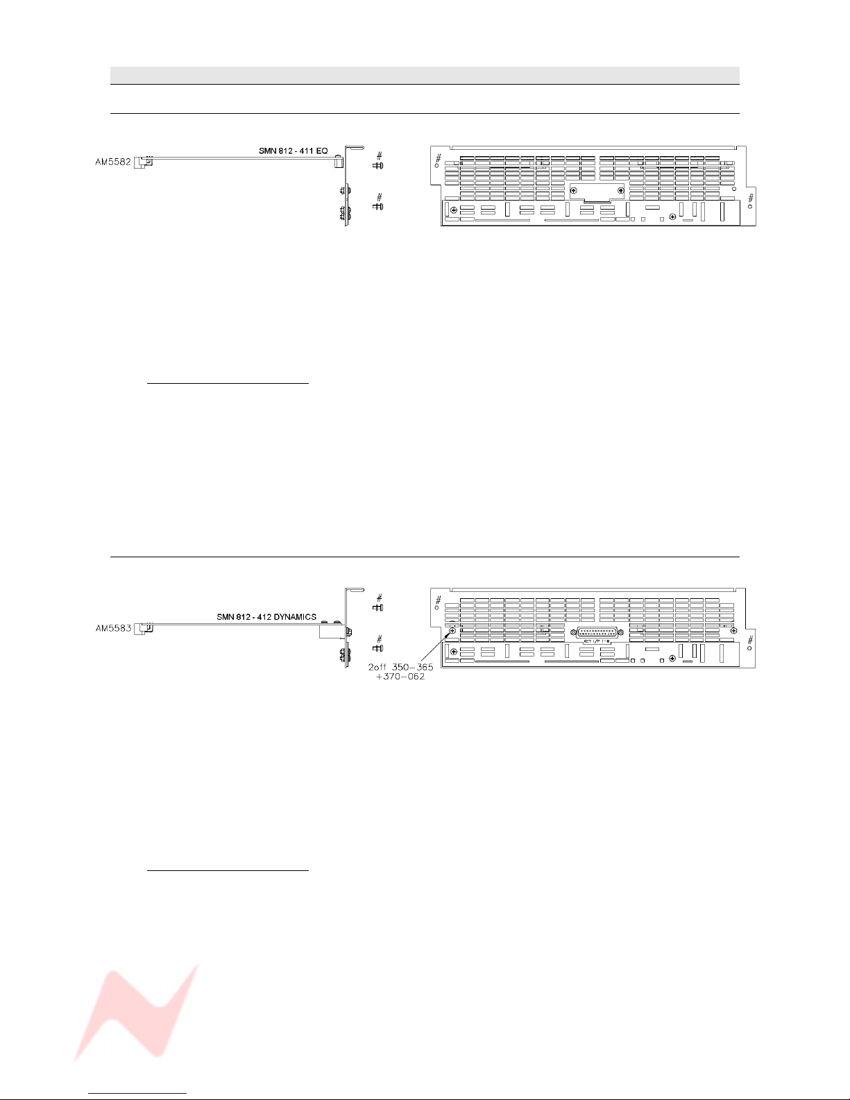
Optional Console Hardware
EQ Cassette
(Part number SMN 812-411)
This cassette provides 8 Channels with classic Neve 1084 EQ (3 bands per channel).
Without this card, the EQ button (and led) on each channel strip will not function.
The EQ button underneath the DAW screen will also be locked out.
When the EQ cassette is present, the parameters are set using the four encoders under the small DAW
screen.
The card itself has no external connectors / pin-outs.
Installation Instructions
> Remove the power to the console.
> Ensure the switch settings have been set correctly for this card 's position.
See Appendix A on Switch Settings at the end of this document.
> Remove the entire ventilation facing plate on the rear of the console by removing the two
screws shown above.
> Slide the EQ cassette into the top-most available slot and push it to the rear until the
connectors mate securely onto the backplane.
> Screw the faceplate back into place.
Dynamics Cassette
(Part number SMN 812 – 412)
The Dynamics cassette provides 8 channels with Dynamics processing (Compressor and Gate, including
the provision of an external Key Input).
This external Key Input is available on both the Gate and Compressor.
Without this card, the DYN button (and led) on each channel strip will not function.
The DYN button under the DAW screen will also be locked out.
When the Dynamics cassette is present, the parameters are set using the four encoders under the small
DAW screen.
Installation Instructions
> Remove the power to the console
> Ensure the switch settings have been set correctly for this card 's position.
See Appendix A on Switch Settings at the end of this document.
> Remove the ventilation facing plate on the rear of the console, and remove the Key Input
blanking plate in the centre.
> Slide the Dynamics cassette into the middle slot and push the card firmly to the rear until the
connectors mate securely onto the backplane.
> Screw the faceplate back into place, ensuring the Key Input D-type connector and two
adjacent pillars comfortably clear the faceplate surface.
> Secure the Key Input D-type connector in place through the faceplate using the adjacent pillars
and two screws.
- 13 -

GENESYS User Manual Issue 1
Channels AD/DA Cassette
(Part number SMN 812 – 410)
This cassette provides 8 channels with AD/DA converters.
Without this card, the DLN and D-MON functionality (and leds) will not be available on the console.
The AD/DA cassette provides facility for digital Lines and digital externals into the desk plus enabling the
Direct Outputs on each channel to be sent digitally.
Installation Instructions
> Remove the power to the console.
> Remove the ventilation facing plate on the rear of the console (shown above) and remove the
connector blanking plates.
> Slide the cassette into the lowest available slot and push it to the rear until the connectors
mate securely onto the backplane.
> Screw the faceplate back into place, ensuring the 3 D-type connectors, support pillars and
cassette connectors comfortably clear the faceplate.
> Secure the 3 D-type connectors in place through the faceplate using the adjacent pillars and
six screws.
On larger consoles, it is possible to have one of each of the above cards for each block of 8 faders
providing EQ, Dynamics and digital lines/externals for the entire console.
For cards not initially present, the connector plates on
the console rear will be fitted with blank panels
instead.
Operational Considerations
If you have an EQ processing cassette installed, it will only be possible to place the EQ on the Channel
path or the Monitor path on a channel, not across both.
Likewise, the Compressor and Gate can only exist on the Channel or Monitor path.
It is not possible to have the Compressor on the Input and the Gate on the Monitor path (or vice versa).
- 14 -

GENESYS User Manual Issue 1
Digital Monitoring Cassette
(Part number SMN 812 – 410)
This single card (regardless of console size), enables all of the Main Mix, 2T, 8T, 5.1 and Auxiliary
Sends to be sent from the desk digitally.
It also allows for a 5.1 Surround digital external input to the loudspeakers.
It is sub-fitted beneath the computer card and consists of 3 x 25-way D-type connectors, plus Firewire
and BNC Sync connectors.
The sample rate that the card is locked to is shown in the four-character alpha display.
Installation Instructions
> Remove the power to the console.
> Remove the ventilation facing plate on the rear of the console (marked # above) and remove
the blanking plate for the cassette connectors.
> Slide the cassette into the slot and push it to the rear until the connectors securely mate onto
the backplane.
> Screw the faceplate back in place, ensuring the 3 D-type connectors (plus support pillars) and
other connectors comfortably clear the faceplate.
> Secure the D-types connectors in place through the faceplate suing the support pillars and two
screws per connector.
These optional processing cassettes are 'plug & play' and do not require any
jumpers or switches to be set to integrate them into the console.
They are automatically detected by the console when it powers up.
For the purposes of this manual, it is presumed the console is fully fitted
with all the available optional hardware & software.
- 15 -
GENESYS User Manual Issue 1
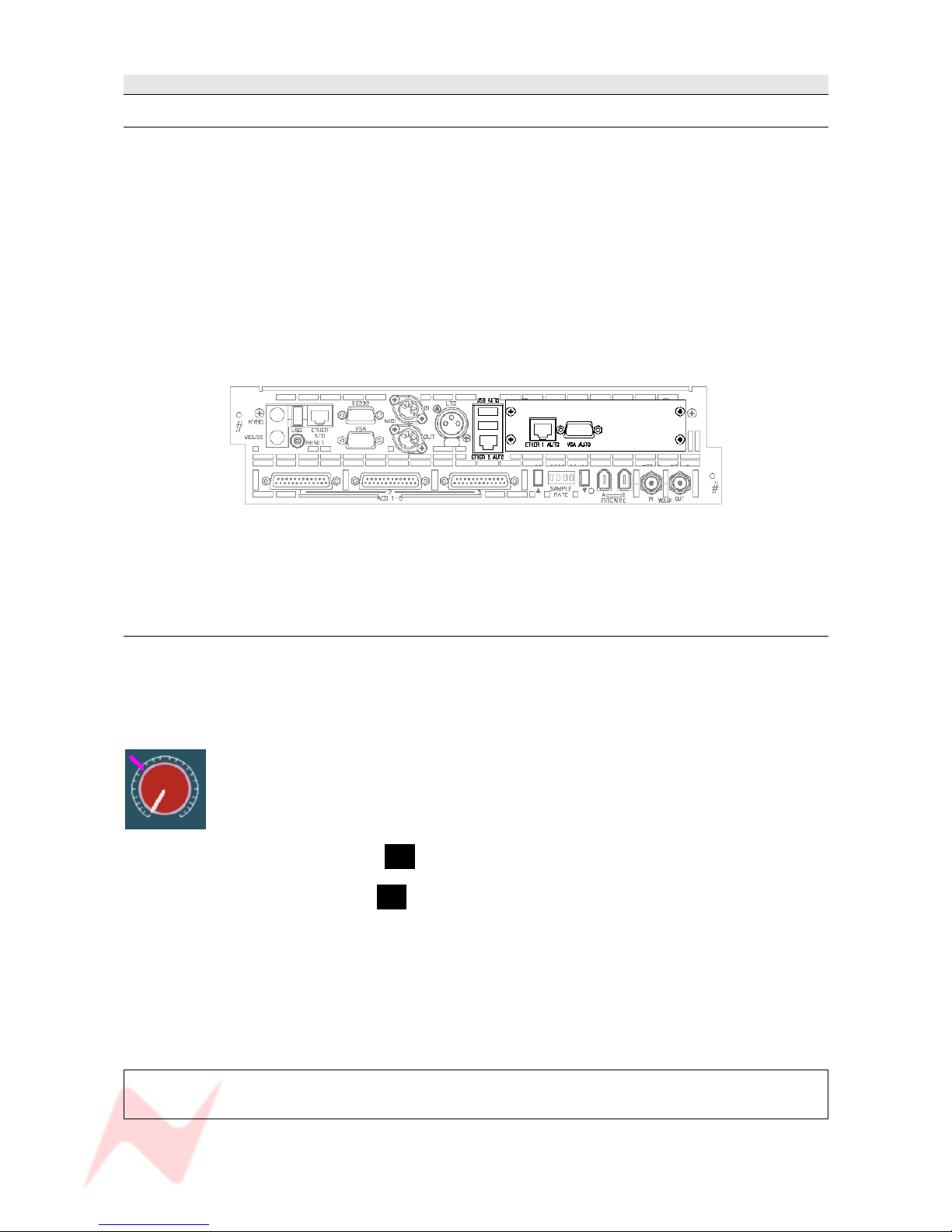
Optional Console Software
Automation
(Requires Part number SMN 812 – 400)
When a console has the optional automation package fitted, it comes with the following additions to a
standard console:
• The Encore Plus™ automation software to record, edit and play back automation of Faders, Cuts and
Channel Events (Aux On/Off, Insert On/Off etc) (not available in this version of software).
• Motorised channel faders, enabling playback of automated moves
• A row of Master Automation buttons next to the Main Output faders for setting the automation
modes (not available in this version of software).
• Shown below, the computer cassette will utillise the additional hardware that contains:
> A VGA output
> 2 USB ports
> Hard drive for storing automation files
> Ethernet connectors used for HUI control and communication
For the purposes of this manual, it is presumed the Automation hardware has been installed.
Recall
The Recall package means that as well as taking snapshots of the console surface as you would on a
standard console (including any internal routing), the Recall software allows you to record the positions
of all rotary controls and switch states so they can be manually matched at a later date providing full
console reset ability.
It does not need any specific hardware to run other than that supplied with a standard console.
As each control is matched by hand, an on-screen graphic will display the position of
the control as you set it, plus an indication of where the control should actually be
(indicated by a purple mark). Once it has been matched, the next control will be
displayed and so on, until all of the surface has been reset.
• If Recall has been fitted, the letter R will be displayed in red in the top right corner of the main
screen just by the timecode display.
• If Recall is not present, the letter R will be displayed in grey instead.
Recall Stores are stored by default in the same location as any Automation files (for ease of use) but they
can be stored in any user-defined location on the system (or network if present).
For the purposes of this manual, it has been presumed that the Recall package has been installed.
See chapter on Recall.
For more information on the optional Automation and Recall packages,
please contact your local Neve distributor.
- 16 -
GENESYS User Manual Issue 1
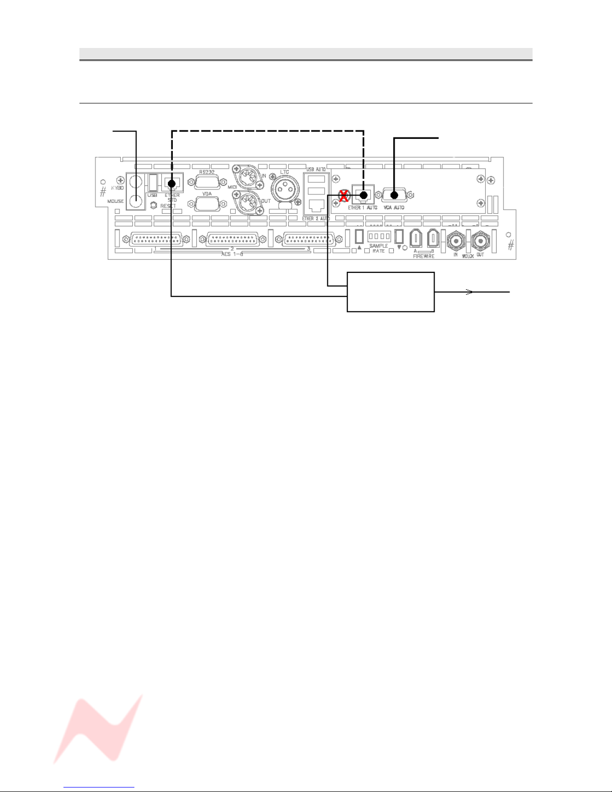
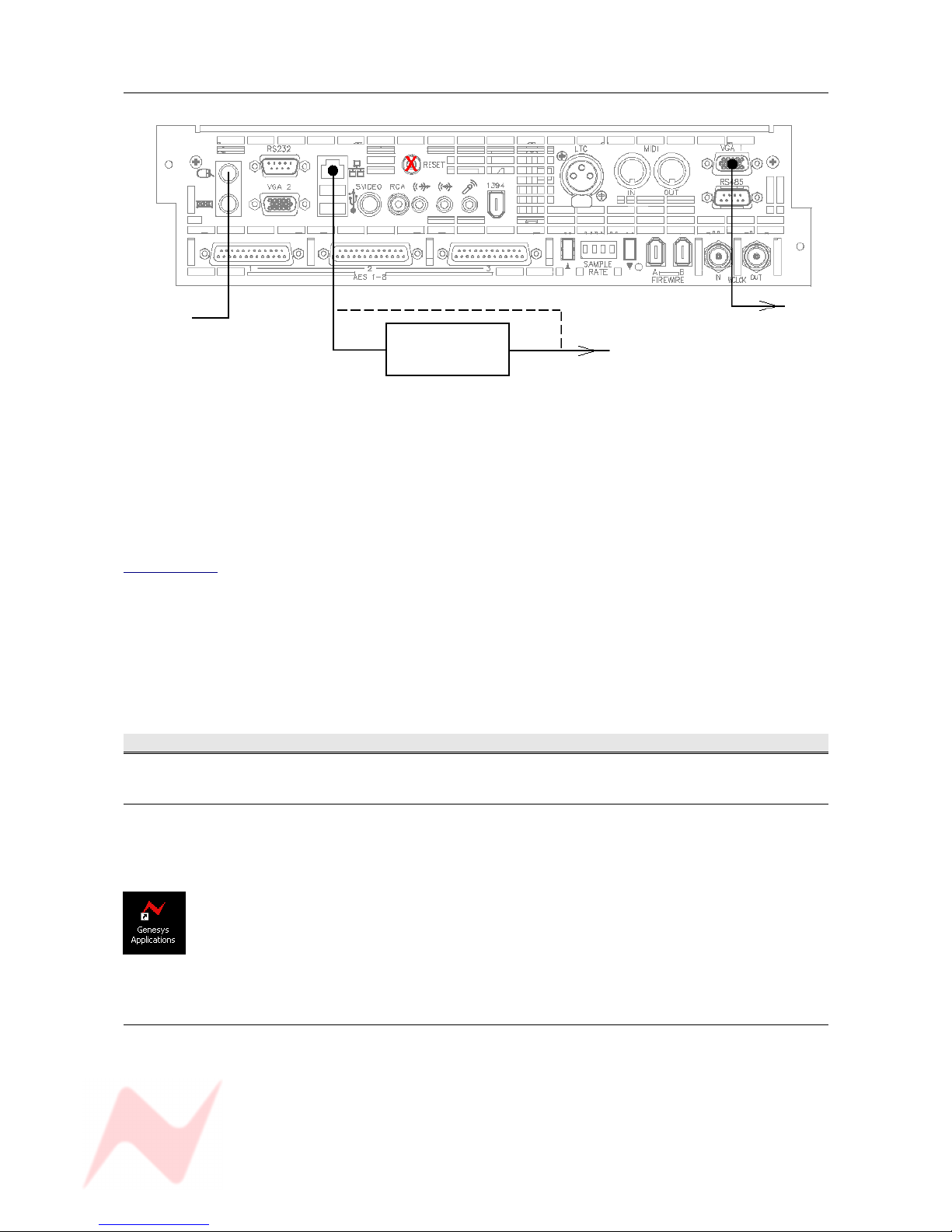
Wiring connections / Setup for HUI control
The type of connections depend on the type of computer cassette installed in the console.
OLD type computer
Mouse Standard supplied
Crossover Ethernet cable To TFT screen
Ethernet Hub
To DAW machine
The dotted lines show the two Ethernet ports connected when the unit is not connected to Pro Tools or an
external DAW (this will mean that the console cannot control HUI paths).
This cable should always be fitted if not controlling a DAW.
If you wish to control HUI paths, remove this cable and connect both console Ethernet ports to an
Ethernet hub, which in turn should then be connected to your DAW.
In either of the above scenarios, the VGA output should be connected to a display screen for Encore
Automation display.
- 17 -
GENESYS User Manual Issue 1
NEW type computer
To TFT screen
Ethernet hub * To DAW
* The Ethernet hub is optional if the computers are not to be networked.
NB:
If you do not wish to run HUI over LAN (Local Area Network) then retain the blue Ethernet cable as
supplied and connect as shown in the upper diagram.
If you wish to run HUI over LAN, connect the Genesys computer as shown, discarding the Ethernet link
cable on old style computer cassettes.
In order to run the HUI control over LAN, you will need to download and install IPMIDI from
www.nerds.de (this is a 3rd-party driver that allows HUI communication across a network) and choose
the one applicable to your DAW system.
Please see your DAW documentation on how to configure the DAW for HUI control.
Powering Procedure
Switch On Procedure
> Switch on the Ethernet hub (if used)
> Switch on the console. The computer should boot Windows XP.
(If not, press the Reset switch on the computer cassette (marked in the above
diagrams with a red X)
> Once into the Windows Desktop, double click the Genesys App application (left).
This will then boot the console.
After about 20 – 30 seconds you will see the Genesys front screen open, at which
point the console will be ready to be used.
Power-down Procedure
> Ensure your work is saved to the relevant medium.
> Shut the XP computer down in the usual way, by selecting Shut Down from the Start menu.
> Turn the Control Room Monitoring knob down as far as it will go OR press the master CUT button for
the speakers.
> Turn the output level on the speaker's amplifier down to CUT, then turn the power off (if using active
speakers, turn each speaker down before removing the power).
> Remove the power to Genesys.
- 18 -
GENESYS User Manual Issue 1
SEL Mode
Channel Sel Mode
> When SEL is selected by holding down and then releasing on a channel
strip, most of that strips functionality plus the ability to change any of the
audio is suspended.
The SEL led will flash to indicate you are in SEL Mode.
It will then be possible to set up Auxiliary Pre-/Post- states, the order of
processing in the Monitor and Channel paths etc.
> When SEL is selected on the 8T faders section , you can set how the
Rev Return signals are fed into the Auxes (either Pre- or Post-).
Monitor SEL Mode
SEL Mode is a setup mode on the Monitor panel where signal path routing,
Cue feeds, loudspeaker trims, output trims, Pre/Post states and other
monitoring setups can be configured.
The majority of these functions can also be configured on the Settings
Screen, see separate chapter).
When LOCK and SEL are pressed together on the ROUTE SEL section of
the Master Panel, most of the Control Room Monitor panel's button display
and functionality – plus the ability to change the audio selection – is
suspended.
(If lit, the D-EXT, AFL/PFL and and RTB leds on this panel will not
extinguish).
When launched from this panel, SEL Mode provides purely a routing
function, and is used for sending Channel and/or Monitor paths to either
the 8T and/or Main Mix.
NB.
The SEL buttons on the channel strips and 8T fader strips are all
interlocked, so that selecting one SEL button will deselect any other SEL
button already pressed.
There is no such interlock between these SEL buttons on the channels
and the SEL button on the ROUTE SEL panel, apart from when the Sel
Route option is ticked on the Setup screen.
With this option ticked, the first single quick press of the SEL button will
bring up the EQ and a double quick press will bring up the DYN display on
the DAW screen; Holding down sel and selecting >8T will also force the
Route Sel panel into SEL Mode by forcing on it's SEL button (as well as
turning over the DAW screen to be the Routing display).
Coming out of SEL Mode returns all audio, leds & buttons to their last
selected display and state.
In this manual, all text relating to SEL Mode is shown with a shaded blue
background.
- 19 -
GENESYS User Manual Issue 1
GENESYS Application Scenarios
In all of the following examples, only the M1 and M2 stereo speaker sets are shown due to limitations
of space. The four speaker sets - A, B, M1 and M2 – are all available.
Please note that only speaker set M1 appears as XLRs on the rear of the console.
All other speaker outputs signals are only available on the 25-way D-type connectors.
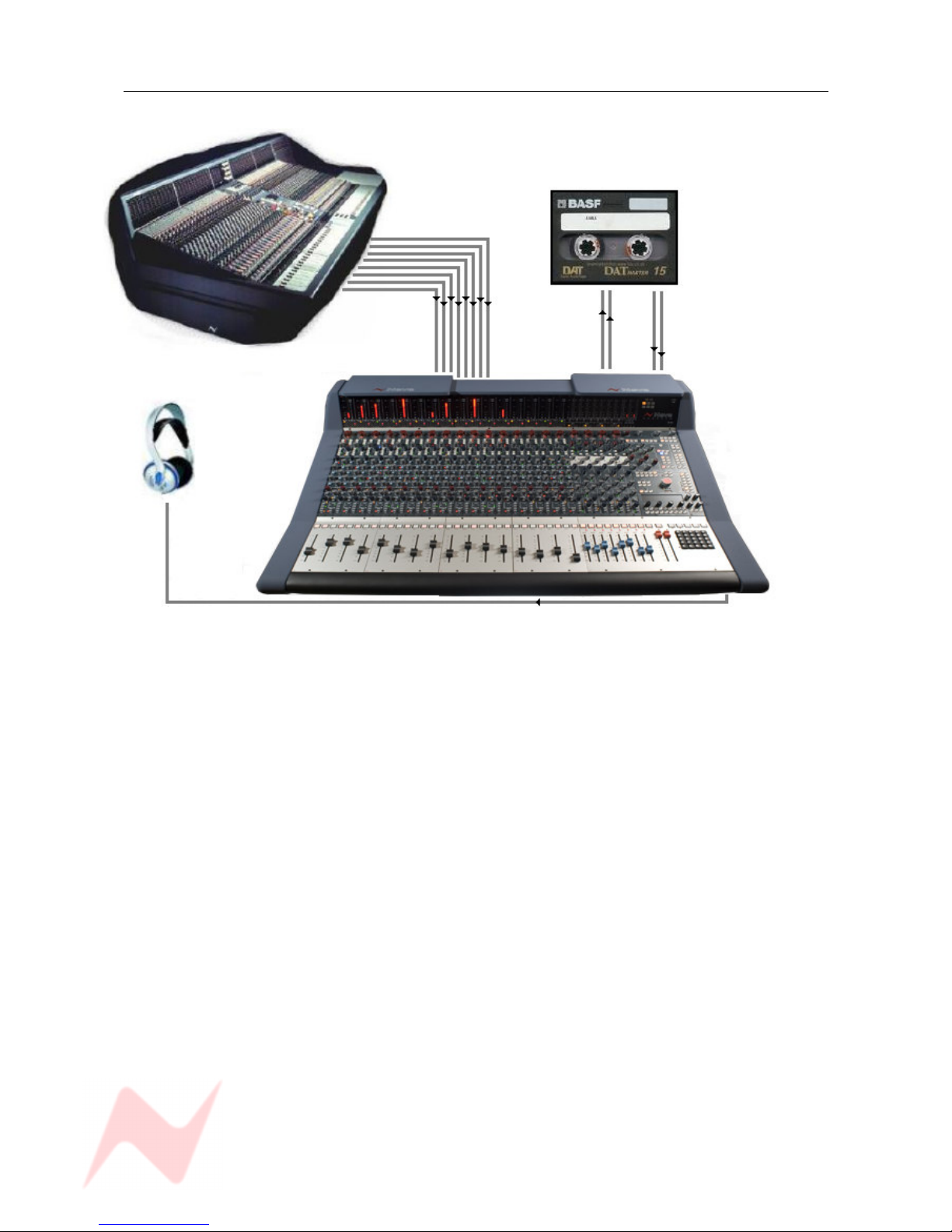
Recording
Line Input
Line Input
Mic Inputs
Pro Tools
Auxiliary Send / Return
Pro Tools I/O Headphones
M1 Speakers
DAW Returns
Main Mix
Output
M2 Speakers
Genesys can be used to monitor from the workstation while recording directly from Mic or Line inputs.
(The Direct Outs can be used from Genesys to the DAW enabling it to be used like a conventional in line
desk with both recording and monitoring signals passing through the unit, connections not shown here).
A collection of signals are input to the desk at once, either using Mic inputs, Line Inputs for keyboards or
other sound modules, and the DAW Returns inputs for signals from the DAW.
Effects units can be connected to the Auxiliary Send & Returns so that a rough working mix can be
achieved.
The Main Mix Output of Genesys is sent to the DAW so that a rough mix can be recorded onto your
workstation.
This can be analogue or digital depending on if you have the optional digital card fitted.
The mix can be monitored on headphones by sending the Main Mix to a Cue and then sending the Cue to
the headphones.
- 20 -
GENESYS User Manual Issue 1
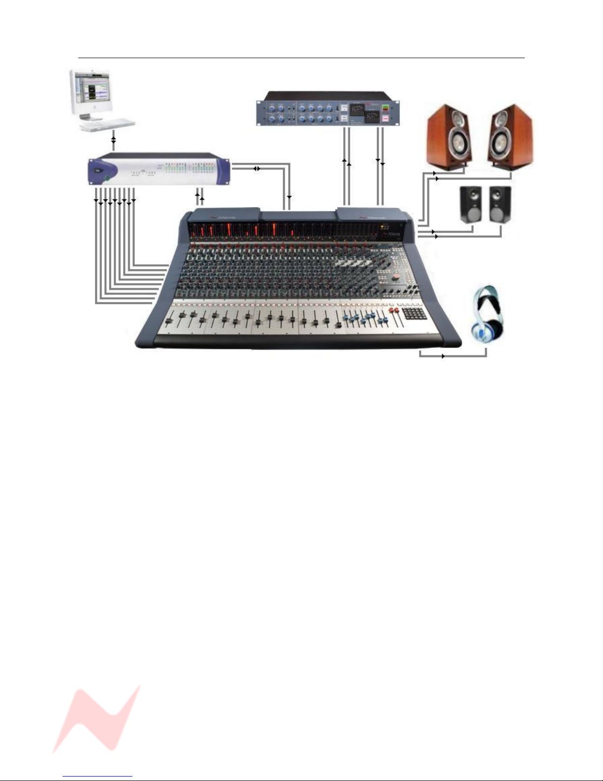
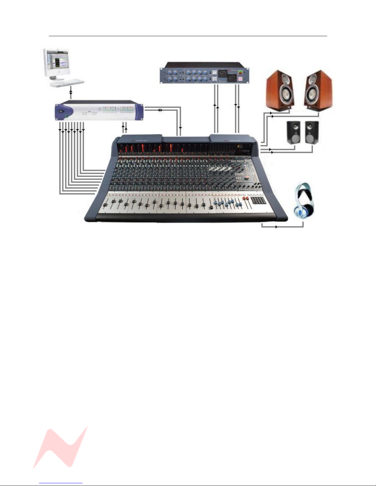
Mixing
Pro Tools Mac / PC Neve 33609 Compressor
M1 speakers
Main Mix Insert Send Return
Pro Tools I/O
Stereo Main
Mix Out
M2 speakers
Engineers
Headphones
DAW RTN 1 - 16
Connect the outputs of the workstation to the inputs of Genesys.
Key elements such as lead vocals and lead instruments should be kept separate within the workstation
and connected to individual inputs on Genesys. Other elements such as backing vocals, effects, etc can
be routed to stereo groups within the workstation and these groups connected to the Genesys inputs.
Optimum sound quality within the workstation is generally achieved by setting the virtual faders to 0dB.
Final mix levels can be set on Genesys.
The mix is now being created on the mix bus of Genesys. This uses the same mix topology
as the classic 88 series Neve consoles and recreates their legendary sound.
Recording back to the DAW or onto another device such as a CDR may be analogue or, if the digital
cassette option is fitted, can be from the Neve Analogue to Digital Converters ensuring the best possible
sound quality.
A Neve 33609 Compressor (or a Neve 8803 EQ unit) can be patched across the Main Mix Insert allowing
the whole mix to be compressed or EQ’d.
Sometimes it is necessary to mix between a clean mix and a processed mix, for example when using a
Filter Bank to create a special effect across the whole mix for one section of a song.
This can be done by patching the filter bank across the Main Mix of Genesys using the Insert Send/Rtn
and then switching it in circuit at the desired time.
The balance between the clean mix and the processed mix is now controlled by the Insert Mix level
control and the engineer can switch between clean and processed mix or balance the two as required.
- 21 -
GENESYS User Manual Issue 1
Live Recording
Front of House console
DAT
Group / matrix Main Mix
outputs into Output
Genesys External 3 inputs
Engineers
Headphones
While the output for the main Front Of House console may be of a high standard, the mix created for the
venue does not have the correct balance for a live recording.
Genesys solves this problem.
The main mix outputs of Genesys should be connected to a recording device such as a DAT or DAW
running on a laptop Mac or PC.
The output of the recording device should be connected to the Ext 3 input on Genesys (Externals 1 and 2
are Surround inputs).
Key elements such as the lead vocal can be connected directly to an input on Genesys from a Direct Out
on the FOH console. Other elements such as drums, keyboards, etc can be connected to the Genesys
inputs either from the Group Outputs or from the Matrix Outputs of the FOH console depending on the
type of FOH console being used.
A correct balance between the individual and pre-mixed sounds can be set up on Genesys using Channel
faders. The mix is now passing through the Genesys mix bus.
The engineer can monitor the live recording on headphones and switch between monitoring the Genesys
Main Output and the Ext 3 return path from the recorder (for a confidence check on the recorded
sound).
- 22 -
GENESYS User Manual Issue 1
Hui Control of DAW (inc Sub-mixing)
Neve 33609 Compressor
Pro Tools Mac / PC M1 speakers
Main Mix Send Return
Pro Tools I/O
Timecode
Ethernet
Main Mix
DAW RTN
1 – 32 to
Genesys
M2 speakers
Engineers
Headphones
In this scenario, the first 16 channels from Pro Tools are fed into the desk at Line level.
This may, for example, be a percussion group that you want to mix on Genesys.
This is sent through a 33609 using the Main Mix Insert and then returned to Pro Tools as a mixed and
finished section.
Pro Tools channels 17 and onwards are controlled via HUI, so even though the audio for these paths does
not pass through the console, it is still balanced and mixed on Genesys using the 8T faders and the
encoders underneath the DAW/Console Control screen.
These faders can be assigned to blocks of 8 Pro Tools paths at a time, so by reassigning this block of
faders, it is possible to manipulate all of the Pro Tools paths.
Any automation data you record for these paths will be stored on Pro Tools.
To enable both the HUI control and the automation, the timecode from Pro Tools needs to be referenced
to Genesys, plus an Ethernet cable for the HUI data needs to be plugged from Pro Tools into Ether 1
Auto on the rear of the console.
Please see the section on HUI Setup to configure communication between Genesys and your DAW.
- 23 -
GENESYS User Manual Issue 1
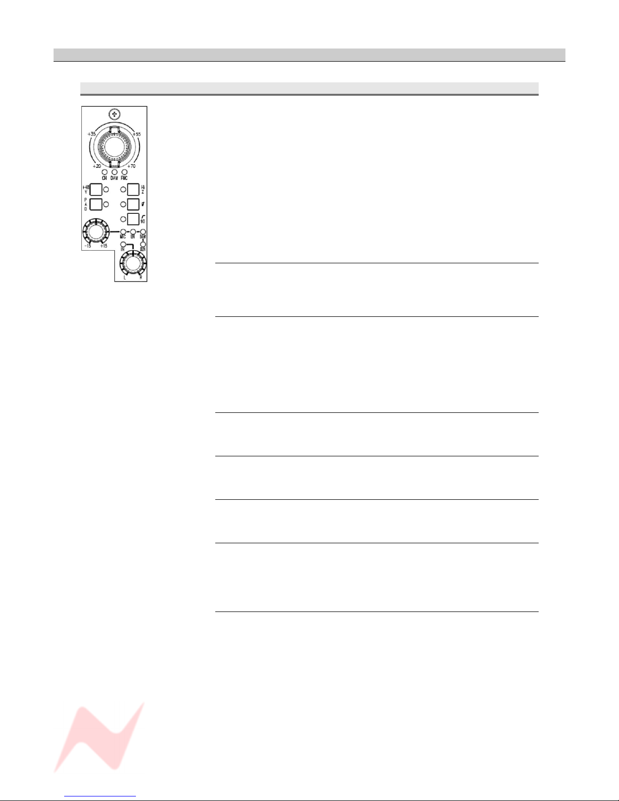
Channel Strip
CHANNEL Section
The free-running Input Level knob attenuates the Input Gain in 11
discreet steps and has a range of +20dB to +70dB, the level being
displayed using the internal leds.
It is also a 3-state toggle control, and pushing the knob will cycle through:
> CHM: Selects the Channel / Mic input
> DAW: Selects CH DAW control (when automation is fitted).
> FNC: Selects from a range of 'soft' inputs which are set on screen.
The selected function will be displayed on the adjacent leds.
It is possible to select a different function for each Channel Strip.
+48v
Supplies 48 volts of phantom power to the Mic input.
NB. Operation of 48v takes 20 seconds to enable and disenable to protect
monitoring loudspeakers. This is indicated by the led flashing.
HI Z
Impedance.
To make allowance for the characteristics of differing microphones.
• The High Impedance electrically balanced input is 3.2K (the
transformer balanced input is 3.1K).
• The Low Impedance electrically balanced input is 1.4K (the
transformer balanced input is 1.3K).
PAD
Reduces the input by -20dB.
Ø
Switches the phase of the incoming signal.
90Hz filter
Switches a hi pass filter in circuit with a 90Hz threshold.
INPUT TRIM
This supplies +/- 15dB of trim to the incoming signal.
> Press the control to cycle the input selection through MIC / LN / DAW /
DLN, shown on the adjacent leds.
L/R
Pan control. This control is a classic 3 db center with S law panning.
> Press to enable.
- 24 -
GENESYS User Manual Issue 1
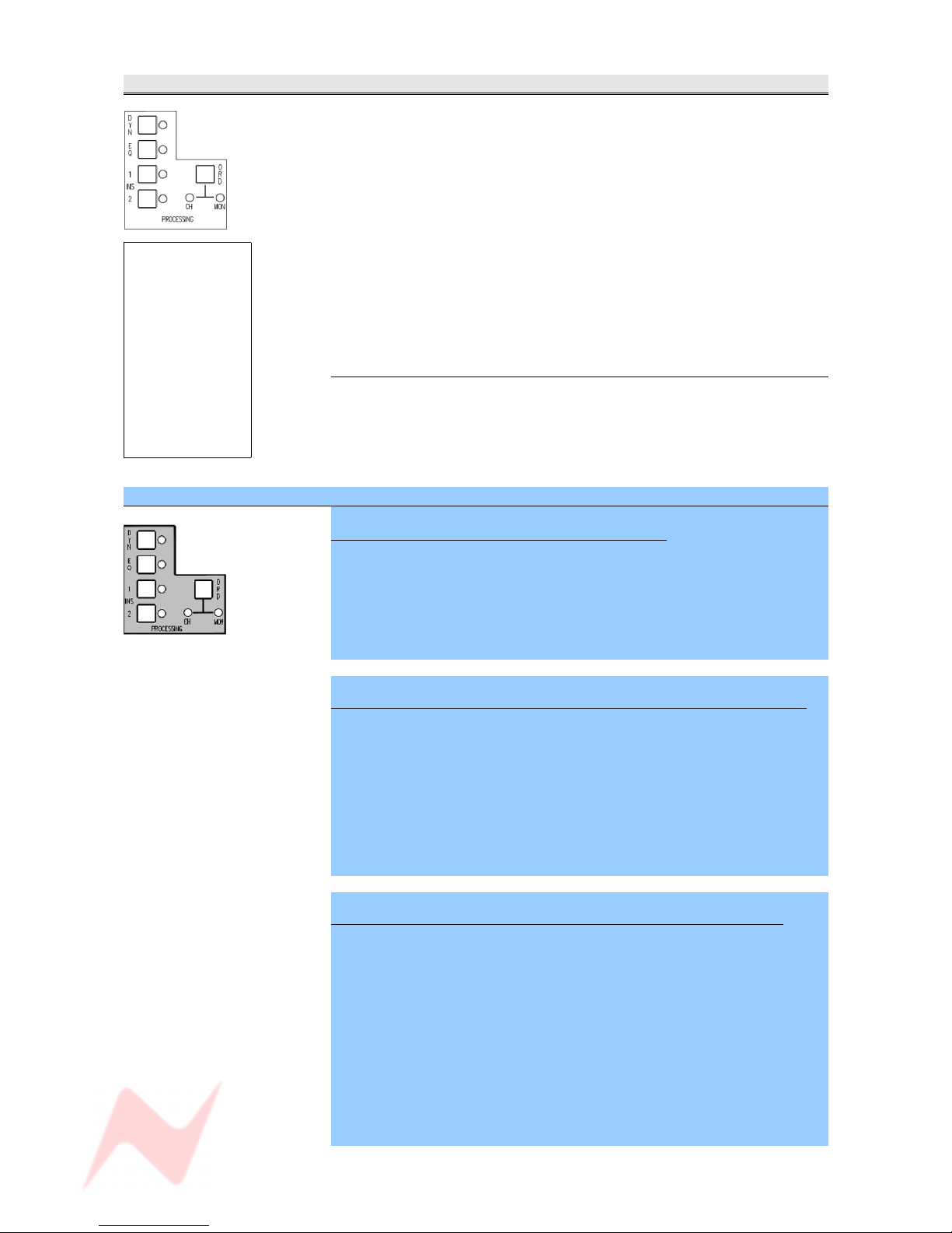
PROCESSING Section
If the optional processing cassettes are present, it is possible to place the
EQ – and/or the Dynamics - on either the Channel or Monitor path (it is
not possible to split the Dynamics elements so the Compressor and Gate
are split between the two paths).
> In normal operation, the buttons work as On/Off for the relevant
process, regardless of whether that element is on the Channel or Monitor
path.
If an element has been placed in the Monitor path, then pressing the
process On/Off in this section will not affect the state of the adjacent led.
Rather, the on/ off state will be displayed by the TO MON leds at the
bottom of the strip.
Secondly, the order of the processing elements can be interrogated.
ORD
> Press the ORD button once and the four leds will light in turn to reflect
the order of processing on the Channel path.
> Press the ORD button again and the four leds will light in turn to reflect
the order of processing on the Monitor path.
SEL Mode on the PROCESSING section
To enter and exit SEL Mode on the Channel Strip
> Hold down and then release the SEL button to enter SEL Mode. This
blocks out the functionality of most
of the strip controls, apart from those indicated in white, left.
> Make any changes.
> Press SEL again to save your changes and exit.
To allocate processing elements across Channel and Monitor paths
> Hold down and then release the SEL button to enter SEL Mode.
> Pressing the EQ button will toggle between the lighting the adjacent led
to indicate the EQ is in the Channel path, or lighting the EQ led in the TO
MON section, to indicate the EQ is in the Monitor path.
The DYN, INS1 and INS2 buttons work in the same way.
> Press SEL again to fix the assignment of processing and return the desk
to normal operation.
To set the order of processing on the Channel and Monitor paths
> Hold down and then release the SEL button to enter SEL Mode.
> Press ORD (the CH led will light).
The process led(s) will flash for any elements that are in the Channel
path.
> Press the buttons in the order you wish the processing to appear.
> Press ORD again (the MON led will light if processing is in the monitor
path already).
The process led(s) will flash for any elements that are in the Monitor path.
> Press the buttons in the order you wish the processing to appear.
> Press SEL to exit SEL Mode and return the console to normal operation.
- 25 -
If the EQ or
Dynamics
cassettes are not
fitted on the
relevant channel
strip, the EQ and
DYN leds will not
light and these
buttons will not
function.
INS1 And INS2
are always
available.
GENESYS User Manual Issue 1
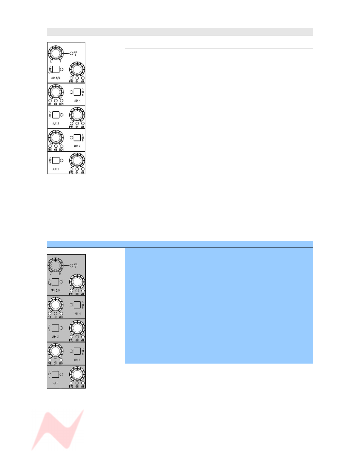
AUXES Section
Master Level
Sets the output contribution of the Aux.
It has a range of -∞ to 0dB.
> Press to enable, and the adjacent led will light.
>8T buttons
Sets the destination and level control for sending the Auxes to the last two
8T busses.
Different destinations apply depending on whether the Aux is mono or
stereo.
• Aux 1 and Aux 3 will be sent to 8T 7
• Aux 2 and Aux 4 will be sent to 8T 8
> Press the >8T button next to the Aux to send it to it's associated 8T bus
(the led will light).
NB:
• Aux 5 and Aux 6 will be sent to both 8T 7 & 8T 8
In it's default state, the PAN and 8T 7/8 buttons apply to Aux 5.
> To set this to be Aux 6, press the PAN control.
The adjacent led will light.
It is not possible to send the same channel to Aux 5 and Aux 6 at the
same time on the same channel.
When an Aux is sent to an 8T bus, then the contribution to the Aux bus is
disconnected but the ON led will still work as normal.
SEL Mode on the AUXES Section
To Set How the Channel and Monitor paths feed the Auxes
Either the Channel or Monitor path can be set to feed the Aux, either Preor Post- fader.
> Hold down and then release the SEL button to enter SEL Mode.
Pressing the level control will cycle the Aux through the following options:
> Channel path, Post- fade (no leds lit)
> Channel path, Pre- fade
> Monitor path, Post- fade
> Monitor path, Pre- fade
At any point in this cycle, press SEL to exit Sel mode, to save your
changes and return to normal operation.
The selection will be displayed on the adjacent leds.
After exiting SEL Mode, pressing the level control will turn the contribution
to that Aux On/Off.
- 26 -

GENESYS User Manual Issue 1
DIRECT OUTPUT Section
Master Level
Sets the level of the Direct Output, and has a range of -∞ to +10dB.
This control is always in circuit.
In it's default state, the Direct Output is fed from the Channel input:
• Pre- processing
• Pre- fader
• Pre- CUT.
(In it's default state, all leds will be off)
The control is a 5-state toggle, and pressing it will cycle the Direct Output
to be fed from:
> Channel input, Pre fader, Pre CUT
> Channel input Post fader, Post CUT
> Monitor input, Pre fader, Pre CUT
> Monitor input, Post fader, Post CUT
These four options are all Post- processing.
NB. When in Mix mode the channel input selection is switch off to prevent
feed back via the DAW.
- 27 -
GENESYS User Manual Issue 1
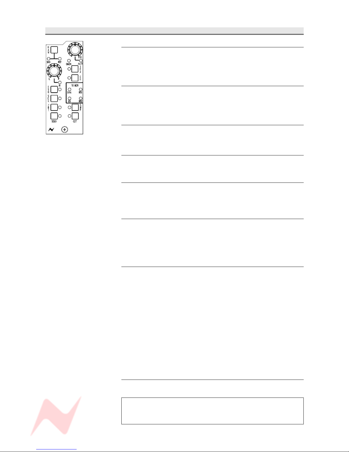
MONITOR Section
L / R Pan
Pan control.
Classic 3dB centre-line pan with S-law shaping.
> Press to enable.
Mon Level Control
Sets the monitor input level, and has a range of -∞ to +10dB.
> Press to select Auto. This will allow the channel encoder to write and
playback monitor levels when automation is being used.
AUT led
Lights red when there is automation data on the Monitor path.
To be functional in V2.0 software.
DAW
> Press to swap the Monitor between the SND and RET.
I/P 2
The second Inputs and the DAW Inputs are merged on this button.
• The led will be On when the second inputs are selected.
• The led will be Off when DMON is On.
CH
Allows you to send the Channel input to monitor, and is a 3-state toggle
switch.
> Press to listen to the Channel input Post-fader (led lights red)
> Press to listen to the Channel input Pre-fader (led lights green)
> Press to return to the Monitor path (led off)
ISO
Isolates the Channel path, Monitor path (or both) from the Solo system.
When other Solos are detected on the console, a CUT will not be applied
to any path that has been isolated.
• For any path not in ISO, the CUT will be destructive (and therefore
affect the Mix output)
• For any path in ISO, the CUT will be safe (and only affect the
monitoring by using the AFL bus).
It has a 4-state toggle, each state indicated by the adjacent led:
> Off: Both the Channel and Monitor path are part of their Solo system.
> Green: The Monitor path is isolated from the Solo system
> Red: The Channel path is isolated from the Solo system.
> Yellow: Both the Channel and Monitor paths are isolated from their
Solo systems.
D-MON led
Indicates the selection of the digital line input to the monitor on each
module.
The D-MON led will only light if DAW, I/P 2 and CH are all deselected
and an AD/DA cassette has been detected in the console.
If there is no cassette fitted, it will not be possible to deselect all the
other Input options.
- 28 -

GENESYS User Manual Issue 1
SEL
Has no intrinsic function in itself, but is used in conjunction with other
buttons on the channel strip for:
• Allocation of processing elements to the Channel and/or Monitor path
• Ordering the processing elements
• Calling EQ and Dynamics controls (single fast-press for EQ, double
fast press for DYN)
• Setting local 8T & Mix routing in conjunction with 8T by holding down
SEL and pressing 8T
• Setting channel strip and fader automation modes
• Setting the Auxiliary PRE and MON states
Putting a channel strip in SEL Mode, only affects that particular strip.
All the other channel strips will continue to operate as normal.
In this manual, all text regarding console setup using SEL Mode is shown
with a blue background.
>8T
This has a 3-state cycle, indicated by the adjacent led:
> Off: The Channel path can be routed to all the 8Ts.
> Red: The Monitor path can be routed to all the 8Ts.
> Green: The Monitor path can be routed to 8T 5 & 6 only (on later
versions it can also be routed to 8T 7 & 8 as well), and the Channel
path can be routed to 8Ts 1, 2, 3, 4 (on earlier versions it can also
be routed to 8T 7 & 8 as well).
(This is a hybrid state designed to work when the console is working
in Surround and group modes.
It can also be used to set up local routing in conjunction with the SEL
button.
SWP
Swaps the large Fader & Cut with the Small monitor knob & Cut within the
Channel and Monitor paths.
SOLO
Solos the path, in either Momentary, Latching or Interlock mode.
CUT
Cuts the path's audio. And also cuts the prefade auxes in mixdown mode.
The CUT can be temporarily over-written by the adjacent SOLO button
and Automation (when fitted).
TO MON leds
Indicates the status of processing.
If any of the INS1, INS2, DYN or EQ leds are lit, this indicates a process
present and switched in circuit on the Monitor path.
The order of the channel processing can be set in SEL Mode.
See previous Channel Section.
- 29 -
A channel strip SEL
button is interlocked
with all other SEL
buttons on the channel
strips and 8T section, so
pressing one SEL button
will cancel any other SEL
button that may be
selected elsewhere on
the console.
It has no interlock with
the SEL button on the
Route Sel panel.

GENESYS User Manual Issue 1
Preventing feedback loops
There are circumstances under which it is possible to create a feedback
loop on the console.
• If the Direct Output is fed from the Monitor (either Pre- or Post-)
and you set the Monitor Input to DAW SND, or
• The Monitor path is set to DAW SND and you set the Direct Output to
Monitor (Pre- or Post-).
To combat this, the console will take steps to prevent this from happening.
• When you toggle through the inputs of the Monitor path, the DAW
Send will not be available, and the DAW SND led will flash twice
without changing from DAW RET.
• If you have DAW SND set, and you toggle through the Direct
Outputs, when you reach Monitor (either Pre- or Post-), the DAW
selection will be forced to RET.
- 30 -
 Loading...