


Neve 8801
Channel Strip
User Manual
527 - 358
Issue 7.3
The 8801 is a combined Mic / Line / Instrument Preamp,
with Dynamics processing, EQ and Insert point.
The Audio Router function provides a user configurable signal path,
allowing any order of Dynamics, EQ, and Insert within the channel path.
In addition, the EQ and/or Filters can be placed in the Dynamics sidechain.

88 Series Outboard / 8801 Issue 7.3
Health & Safety Notice
For your own safety and for the protection of others,
please observe the following safety instructions:
• Read these instructions.
• Heed all safety warnings.
• Do not use near water.
• Clean only with a dry cloth.
• Do not install near heat sources.
• Do not block ventilation openings.
• Protect the power cord.
• Only use accessories specified by the manufacturer.
• Unplug when unused for long periods of time.
• Refer all servicing to qualified personnel only.
• This equipment can only be used with the power supply unit provided with it:
XP Model Number, AEH130PS36
AMS NEVE
Billington Road
Burnley
Lancs
BB11 5UB
England
Phone +44 (0)1282 457011
Fax: +44 (0)1282 417282
Email: info@ams-neve.com
Web: www.ams-neve.com
Support: www.ams-neve.info/crm/fault_report.html
© 2007-2010 AMS Neve Ltd own the copyright of all information and drawings contained in this manual
which are not to be copied or reproduced by any means or disclosed in part or whole to any third party
without written permission.
As part of our policy of continual product improvement, we reserve the right to alter specifications
without notice but with due regard to all current legislation.
Disclaimer: The information in this manual has been carefully checked and is believed to be accurate at
the time of publication. However, no responsibility is taken by us for inaccuracies, errors or omissions
nor any liability assumed for any loss or damage resulting either directly or indirectly from use of the
information contained within it.
Trademarks: All trademarks are the property of their respective owners and are hereby acknowledged.
- 2 -

88 Series Outboard / 8801 Issue 7.3
Table of Contents
Health & Safety Notice.......................................................................................................2
1 - Introduction.................................................................................................................5
Package Contents.......................................................................................................................5
System Requirements.................................................................................................................5
Brief Description & Characteristics................................................................................................6
2 - Front Panel Controls.....................................................................................................7
On/Off Switch............................................................................................................................7
Input Section.............................................................................................................................7
Line Input.........................................................................................................................7
Mic Input...........................................................................................................................7
PAD..................................................................................................................................7
Phantom Power..................................................................................................................7
DI Input............................................................................................................................7
Digital (Genie) Input...........................................................................................................7
Phase Button.....................................................................................................................8
Filters Section............................................................................................................................8
High Pass Filter..................................................................................................................8
Low Pass Filter...................................................................................................................8
Filters to Sidechain.............................................................................................................8
Dynamics Section.......................................................................................................................8
Dynamics Button................................................................................................................8
Dynamics Sidechain...................................................................................................................8
Limiter/Compressor....................................................................................................................9
Knee.................................................................................................................................9
Link..................................................................................................................................9
Attack Time.......................................................................................................................9
Auto Release.....................................................................................................................9
Gain Reduction..................................................................................................................9
Expander/Gate.........................................................................................................................10
Key Input........................................................................................................................10
Hysteresis.......................................................................................................................10
Expander.........................................................................................................................10
Invert/Ducker..................................................................................................................10
Gain Reduction.................................................................................................................10
EQ Section..............................................................................................................................11
EQ Button........................................................................................................................11
EQ TO SIDECHAIN Button..................................................................................................11
Low Frequency Band.........................................................................................................11
Low Mid Frequency Band...................................................................................................11
High Mid Frequency Band..................................................................................................11
High Frequency Band........................................................................................................11
Insert.....................................................................................................................................11
Audio Router............................................................................................................................12
Determining the current channel path.................................................................................12
Audio Routing Screen................................................................................................................13
Output Section.........................................................................................................................13
Bargraph LED Meter.................................................................................................................14
Overload.................................................................................................................................14
3 - Rear Panel..................................................................................................................15
Rear Panel Audio Connections....................................................................................................15
Line Input........................................................................................................................15
Mic Input.........................................................................................................................15
DI Input..........................................................................................................................15
- 3 -

88 Series Outboard / 8801 Issue 7.3
Key input........................................................................................................................15
Dynamics Sidechain Link...........................................................................................................16
Insert.............................................................................................................................16
Line Output.....................................................................................................................16
Headphone......................................................................................................................16
Rear Panel Power section..........................................................................................................17
Warning symbols..............................................................................................................17
USB................................................................................................................................17
Technical Earth Switch......................................................................................................17
Fuse...............................................................................................................................18
Power DIN socket.............................................................................................................18
4 - Optional Digital board.................................................................................................19
Analogue to Digital Converter - AES/EBU (AES 3) & DSD...............................................................19
Sampling Frequency Selection............................................................................................19
Digital Sync.....................................................................................................................19
Double Rate AES Output....................................................................................................19
DSD................................................................................................................................20
Headroom.......................................................................................................................20
75 Ohm WCLK..................................................................................................................20
Installation procedure...............................................................................................................20
5 - Firmware Upgrades....................................................................................................21
Selecting a File for Transfer.......................................................................................................21
File Downloading......................................................................................................................21
Corrupted or Old Firmware........................................................................................................22
6 - Recall Software Installation........................................................................................23
Installation for PC.....................................................................................................................23
Installation for Mac...................................................................................................................25
7 - Other Information......................................................................................................26
Rack Mounting and Cooling........................................................................................................26
Dimensions..............................................................................................................................26
Performance Specifications........................................................................................................26
-----+-----
8 – Block Diagrams
8801
Optional ADC board installation
In the unlikely even that this unit should malfunction or develop a fault,
then please register the fault details on our website, by clicking the link
below.
You will also need to enter the unit's serial number when you do this, so
please have this to hand.
http://www.ams-neve.info/crm/fault_report.html
Once the fault details have been registered, one of our technical support
team will be in touch via email.
This link should also be used for further operational or technical help, or
any general enquiry about the unit.
- 4 -

88 Series Outboard / 8801 Issue 7.3
1 - Introduction
Thank you for choosing the Neve 8801.
This unique channel strip is based on the channel strip featured in the world
renowned 88R mixing desk.
It contains the highest quality Mic / Line / Instrument Preamp, Dynamics
processing, EQ and Insert.
The Audio Router function provides a user configurable signal path allowing
any order of Dynamics, EQ, and Insert within the channel path.
In addition, the EQ and or filters can be placed in the Dynamics sidechain.
The configuration of the unit can be stored and recalled via the Neve Recall
software on a PC or Mac.
Up to sixteen 88 series units may be connected to a Recall system
simultaneously in any combination.
Package Contents
Please check that your 8801 package contains each of the following:
• 8801 unit
• External power supply
• Power lead
• User Manual CD
System Requirements
The 8801 may be used as a standalone unit.
If you wish to use the units Recall facility, it should be connected directly to
the computer or via a powered USB hub but not via a passive USB hub.
If you wish to use the Neve Recall software to store and reload user
configurations you must have one of the following supported operating
systems:
PC:
• Windows 2000, with Service Pack 4 or later
• Windows XP, with Service Pack 6 or later
Mac:
• Mac OS 10.3.9 or later
- 5 -

88 Series Outboard / 8801 Issue 7.3
Brief Description & Characteristics
• High quality transformer coupled microphone preamplifier identical to that
used on the 88R console with 0dB to 70dB of gain.
• Switchable Phantom Power.
• 20dB Pad on Microphone and DI inputs.
• Line input with -24dB to +24dB of gain.
• High impedance DI input.
• Phase inversion switch.
• Overload indication at each gain stage.
• High Pass and Low Pass filters switchable between channel path and
Dynamics sidechain.
• Dynamics processing based on 88R circuitry.
• Compression/Limiting with auto release.
• Gate/Expander/Ducker.
• Dynamics Sidechain linkable to other 8801 units.
• Key input.
• Compressor and Gate gain reduction meters.
• Balanced switchable Insert.
• 4 band EQ based on the 88R console, switchable between channel path
and Dynamics sidechain.
• User definable channel path through Dynamics/Insert/EQ using Audio
Router function.
• Line output with +10dB of gain control.
• Headphone output.
• Optional Digital Output Card (AES/EBU/DSD).
• User recall/store current state via Neve Recall software.
• USB link to PC or Mac.
- 6 -
88 Series Outboard / 8801 Issue 7.3
2 - Front Panel Controls
On/Off Switch
The Neve Logo Switch on the right hand side of the front panel switches the
unit on and off.
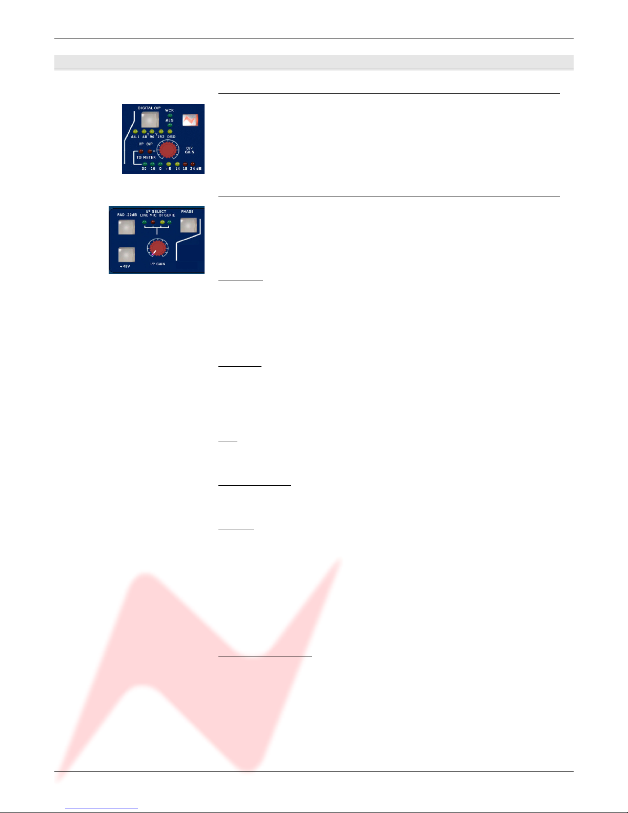
Input Section
On power up, the default input selection will be Line.
The input selected is shown by the LEDs above the gain knob and is selected
by pressing the I/P GAIN knob.
Line Input
The line input is accessible via the rear panel combo connector (¼’’ Jack or
XLR). It accommodates both balanced and unbalanced input signals.
The Gain is variable from -24dB to +24dB using the I/P Gain knob on the
front panel.
Mic Input
The mic input uses the female XLR input of the front panel combo connector
or the female XLR input on the rear panel.
Gain is variable from +20dB to +70dB using the I/P Gain knob.
PAD
The Pad button provides 20dB of attenuation on Mic and DI inputs.
Phantom Power
The +48V button enables phantom power on the Mic input.
DI Input
The DI input uses the ¼’’ jack input of the front panel combo connector or
the ¼’’ jack input on the rear panel.
The input uses a high impedance instrumentation amplifier (>750k), and
accommodates both balanced and unbalanced inputs.
Gain is variable from -24dB to +24dB using the I/P Gain knob.
When Pad is switched on the input impedance changes to 100k.
Digital (Genie) Input
The Digital (Genie) input is available via an optional daughter card.
The input is only selectable when this optional card is fitted.
- 7 -
88 Series Outboard / 8801 Issue 7.3
Phase Button
All inputs can be phase reversed using the Phase button.
The Phase button will illuminate to indicate a phase inversion between input
and output.
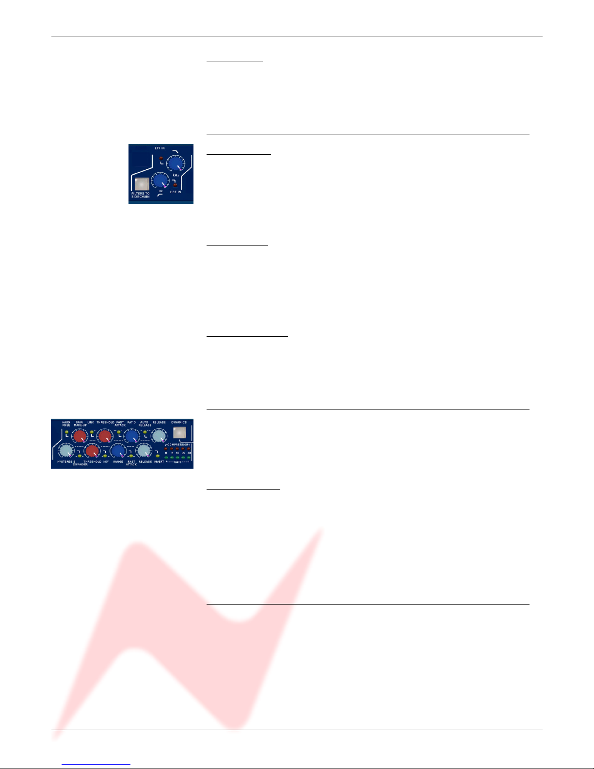
Filters Section
High Pass Filter
The high pass filter has a 12dB per octave (20dB per decade) slope and a
frequency range from 30Hz to 300Hz.
It is switched into circuit by pressing the High Pass frequency knob.
The associated led lights to indicate activation.
Low Pass Filter
The low pass filter has a 12dB per octave (20dB per decade) slope and a
frequency range from 1.5kHz to 18kHz.
It is switched into circuit by pressing the Low Pass frequency knob.
The associated LED lights to indicate activation.
Filters to Sidechain
The Filters To Sidechain button puts both filters in the sidechain.
When the filters are in the sidechain they are not available in the channel
path and vice versa.
Dynamics Section
Full Limiter/Compressor and Gate/Expander facilities are available.
The Limiter/Compressor uses the top row of controls and the Expander/Gate
uses the bottom row of controls.
Dynamics Button
The Dynamics button activates the Dynamics section.
When illuminated, both Compressor/Limiter and Expander/Gate functions are in
circuit.
When not illuminated both are bypassed.
• To disable the Compressor, set Threshold to +20dBu and Ratio to 1.
• To disable the Gate set Range to 0dB.
Dynamics Sidechain
The dynamics sidechain is the control signal for the dynamics processing.
By default the sidechain receives the signal picked up at the input of the
Dynamics gain stage.
The Filters and EQ can be moved to the sidechain path by pushing the Filters
to Sidechain and EQ To Sidechain buttons respectively.
When in the sidechain the Filters and EQ do not act on the channel path.
- 8 -
88 Series Outboard / 8801 Issue 7.3
When Key Input is enabled (by pressing the Gate Threshold knob) the
sidechain receives the signal from the Key Input located on the rear panel on
the D-Type connector.
Limiter/Compressor
The Limiter/Compressor has knobs for:
• Up to 30dB of gain make-up
• Pressing the Gain Make Up knob toggles Hard and Soft Knee
• Threshold has a range of -30dBu to +20dBu
• Pressing the Threshold knob selects Link
• Ratio of 1:1 to limiting
• Pressing the Ratio knob toggles Normal and Fast Attack time
• Release times from 30ms to 3s
• Pressing the Release knob toggles between Release and Auto Release
Knee
The compressor has soft knee characteristics as default with hard knee
available by pressing the Gain Make Up knob.
Link
Link can be selected by pressing on the Threshold knob.
When enabled, the compressor section of the unit can be controlled by the
sidechain of other linked 8801 units.
For example, this allows a stereo input across two modules to be compressed
by the same amount, maintaining the stereo image.
There is no Master/Slave relationship, the priority is such that the strongest
signal always wins.
Multiple units can be linked together using the rear panel D-Type connector.
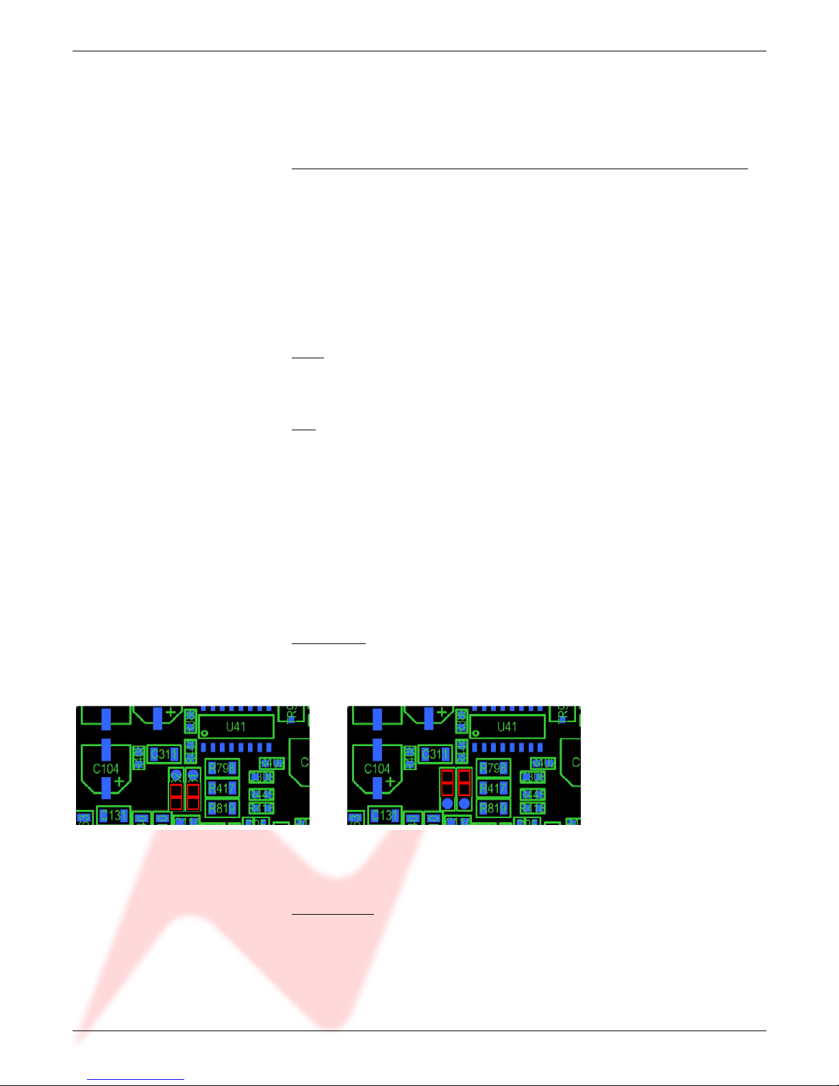
Attack Time
Pressing on the Ratio knob toggles between Normal and Fast Attack time.
Two jumpers inside the unit (shown in red below) allow for two variations of
attack times.
Default Position Alternative Position
Normal Attack time: 8ms Normal Attack time: 3ms
Fast Attack time: 2ms Fast Attack time: 0.5ms
Auto Release
Pressing on the Release knob switches to Auto Release - a triple timeconstant, programme dependent release time.
Anti pumping and breathing circuitry allows the unit to operate on the source
musically whilst retaining absolute control over the dynamic range.
- 9 -
 Loading...